M atrixRIBsynthes.vo.llnwd.net/o16/LLNWMB8/INT Mobile/Synthes... · 2015-05-04 · Radio Frequency...
70
SURGICAL TECHNIQUE This publication is not intended for distribution in the USA. MatrixRIB ™
Transcript of M atrixRIBsynthes.vo.llnwd.net/o16/LLNWMB8/INT Mobile/Synthes... · 2015-05-04 · Radio Frequency...

SURGICAL TECHNIQUE
This publication is not intended for distribution in the USA.
MatrixRIB™

WarningThis description alone does not provide sufficient background for direct use of the instrument set. Instruction by a surgeon experienced in handling these instruments is highly recommended.
Processing, Reprocessing, Care and MaintenanceFor general guidelines, function control and dismantling of multi-part instruments, as well as processing guidelines for implants, please contact your local sales representative or refer to: http://emea.depuysynthes.com/hcp/reprocessing-care-maintenanceFor general information about reprocessing, care and maintenance of Synthes reusable devices, instrument trays and cases, as well as processing of Synthes non-sterile implants, please consult the Important Information leaflet (SE_023827) or refer to: http://emea.depuysynthes.com/hcp/reprocessing-care-maintenance

MatrixRIB Surgical Technique DePuy Synthes 1
TABLE OF CONTENTS
INTRODUCTION Background 2
Magnetic Resonance Imaging (MRI) 6
Intended use, Indications, Contraindications, Warnings, and MRI Information 7
MatrixRIB 11
AO Principles 13
SURGICAL TECHNIQUE Patient Positioning 14
Plating Rib 15
Splint Insertion 25
MIPO INSTRUCTIONS Minimally Invasive Plate Osteosynthesis (MIPO) 33
MatrixRIB Trocar Instruments Instructions 34
Threaded Reduction Tool Instructions 37
90° Screwdriver for MatrixRIB System Instructions 40
CHEST WALL DEFECT REPAIR Chest Wall Reconstruction, including Spanning Gaps 42
Chest Wall Deformity Repair 53
PRODUCT INFORMATION Implants 57
Instruments 58
REFERENCES References 65
2 DePuy Synthes MatrixRIB Surgical Technique
RIB FRACTURES
BACKGROUND
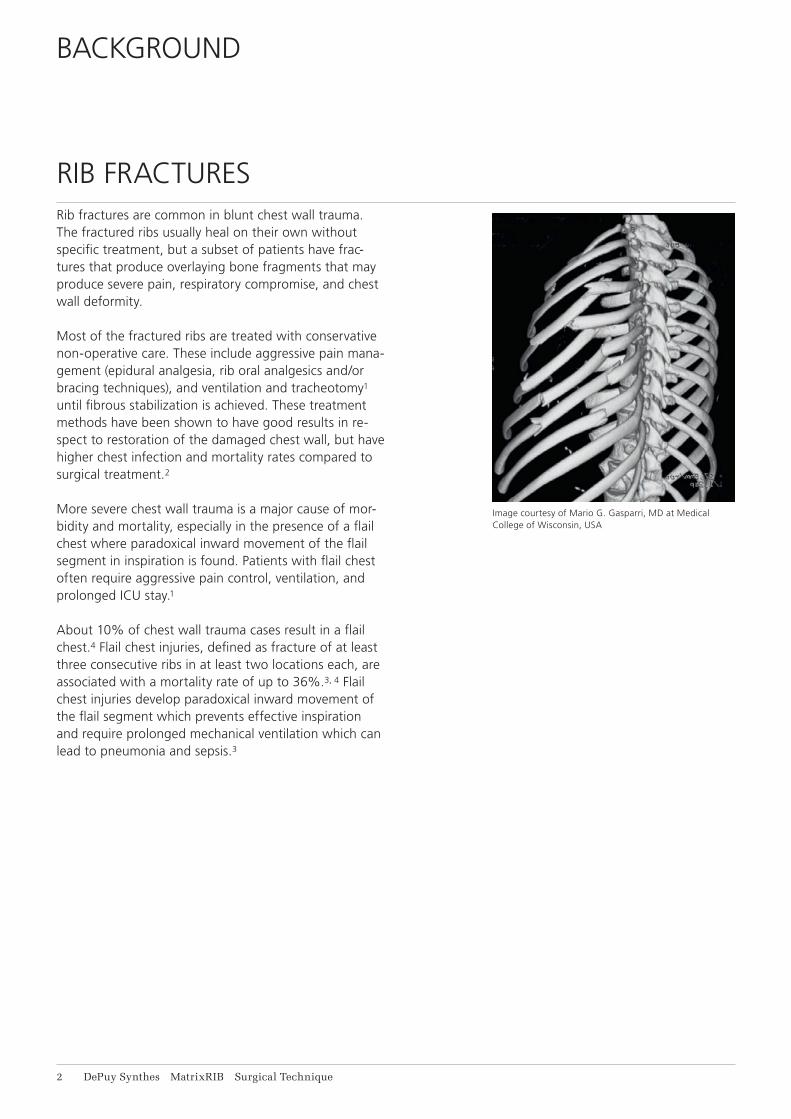
Rib fractures are common in blunt chest wall trauma. The fractured ribs usually heal on their own without specific treatment, but a subset of patients have frac-tures that produce overlaying bone fragments that may produce severe pain, respiratory compromise, and chest wall deformity.
Most of the fractured ribs are treated with conservative non-operative care. These include aggressive pain mana-gement (epidural analgesia, rib oral analgesics and/or bracing techniques), and ventilation and tracheotomy1 until fibrous stabilization is achieved. These treatment methods have been shown to have good results in re-spect to restoration of the damaged chest wall, but have higher chest infection and mortality rates compared to surgical treatment.2
More severe chest wall trauma is a major cause of mor-bidity and mortality, especially in the presence of a flail chest where paradoxical inward movement of the flail segment in inspiration is found. Patients with flail chest often require aggressive pain control, ventilation, and prolonged ICU stay.1
About 10% of chest wall trauma cases result in a flail chest.4 Flail chest injuries, defined as fracture of at least three consecutive ribs in at least two locations each, are associated with a mortality rate of up to 36%.3, 4 Flail chest injuries develop paradoxical inward movement of the flail segment which prevents effective inspiration and require prolonged mechanical ventilation which can lead to pneumonia and sepsis.3
Image courtesy of Mario G. Gasparri, MD at Medical College of Wisconsin, USA

MatrixRIB Surgical Technique DePuy Synthes 3
The need to improve rib fracture treatment has been reco gnized for many years and some surgeons have been using operative approaches including plates, intra-medullary devices, vertical bridging, wire, sutures, and struts to repair the chest wall.2, 3, 4, 5, 6, 7, 8, 9
These attempts indicate a trend in better rib fracture treatment to improve pain control, reduce duration of me-chanical ventilation, reduce ICU stays, reduce the risk for chest wall deformities and ultimately improve patient care.
4 DePuy Synthes MatrixRIB Surgical Technique
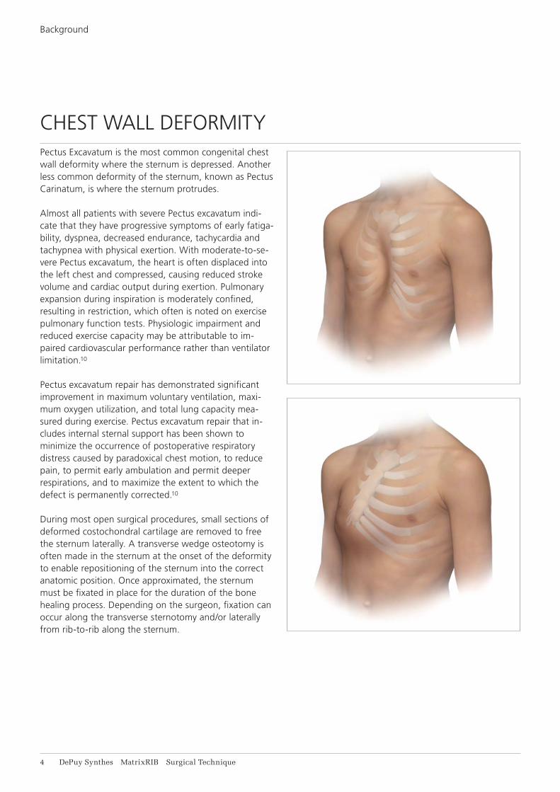
CHEST WALL DEFORMITYPectus Excavatum is the most common congenital chest wall deformity where the sternum is depressed. Another less common deformity of the sternum, known as Pectus Carinatum, is where the sternum protrudes.
Almost all patients with severe Pectus excavatum indi-cate that they have progressive symptoms of early fatiga-bility, dyspnea, decreased endurance, tachycardia and tachypnea with physical exertion. With moderate-to-se-vere Pectus excavatum, the heart is often displaced into the left chest and compressed, causing reduced stroke volume and cardiac output during exertion. Pulmonary expansion during inspiration is moderately confined, resulting in restriction, which often is noted on exercise pulmonary function tests. Physiologic impairment and reduced exercise capacity may be attributable to im-paired cardiovascular performance rather than ventilator limitation.10
Pectus excavatum repair has demonstrated significant improvement in maximum voluntary ventilation, maxi-mum oxygen utilization, and total lung capacity mea-sured during exercise. Pectus excavatum repair that in-cludes internal sternal support has been shown to minimize the occurrence of postoperative respiratory distress caused by paradoxical chest motion, to reduce pain, to permit early ambulation and permit deeper respirations, and to maximize the extent to which the defect is permanently corrected.10
During most open surgical procedures, small sections of deformed costochondral cartilage are removed to free the sternum laterally. A transverse wedge osteotomy is often made in the sternum at the onset of the deformity to enable repositioning of the sternum into the correct anatomic position. Once approximated, the sternum must be fixated in place for the duration of the bone healing process. Depending on the surgeon, fixation can occur along the transverse sternotomy and/or laterally from rib-to-rib along the sternum.
Background
MatrixRIB Surgical Technique DePuy Synthes 5
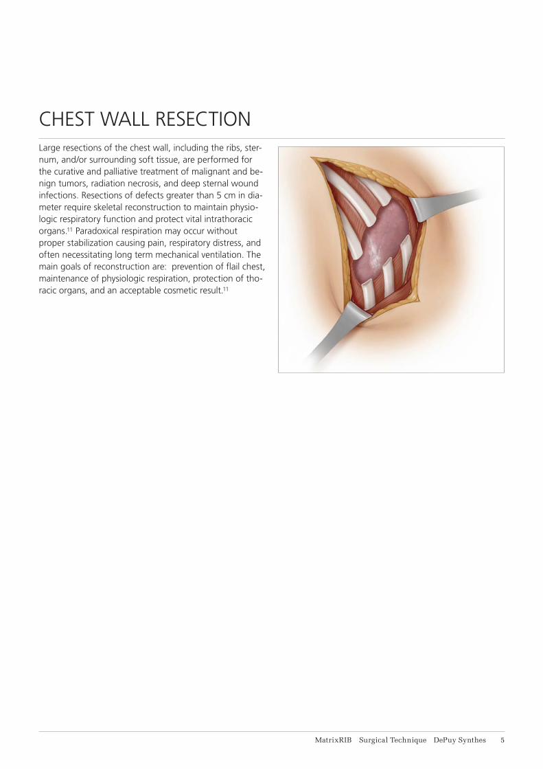
CHEST WALL RESECTIONLarge resections of the chest wall, including the ribs, ster-num, and/or surrounding soft tissue, are performed for the curative and palliative treatment of malignant and be-nign tumors, radiation necrosis, and deep sternal wound infections. Resections of defects greater than 5 cm in dia-meter require skeletal reconstruction to maintain physio-logic respiratory function and protect vital intrathoracic organs.11 Paradoxical respiration may occur without proper stabilization causing pain, respiratory distress, and often necessitating long term mechanical ventilation. The main goals of reconstruction are: prevention of flail chest, maintenance of physiologic respiration, protection of tho-racic organs, and an acceptable cosmetic result.11

6 DePuy Synthes MatrixRIB Surgical Technique
MAGNETIC RESONANCE IMAGING (MRI)
Torque, Displacement and Image Artifacts according to ASTM F 2213-06, ASTM F 2052-06e1 and ASTM F2119-07Non-clinical testing of worst case scenario in a 3 T MRI system did not reveal any relevant torque or displace-ment of the construct for an experimentally measured local spatial gradient of the magnetic field of 5.4 T/m. The largest image artifact extended approximately 35 mm from the construct when scanned using the Gradient Echo (GE). Testing was conducted on a single Siemens Prisma 3 T MRI system.
Radio Frequency (RF)-induced heating according to ASTM F2182-11aNon-clinical electromagnetic and thermal simulations of worst case scenario lead to temperature rises of 21.7 °C (1.5 T) and 12.4 °C (3 T) under MRI Conditions using RF Coils (whole body averaged specific absorption rate (SAR) of 2 W/kg for 15 minutes).
Precautions: The above mentioned test relies on non-clinical testing. The actual temperature rise in the patient will depend on a variety of factors be-yond the SAR and time of RF application. Thus, it is recommended to pay particular attention to the fol-lowing points: • It is recommended to thoroughly monitor patients
undergoing MRI scanning for perceived tempera-ture and/or pain sensations.
• Patients with impaired thermo regulation or tem-perature sensation should be excluded from MRI scanning procedures.
• Generally it is recommended to use an MRI system with low field strength in the presence of conduc-tive implants. The employed specific absorption rate (SAR) should be reduced as far as possible.
• Using the ventilation system may further contrib-ute to reduce temperature increase in the body.
MatrixRIB Surgical Technique DePuy Synthes 7
INTENDED USE, INDICATIONS, CONTRAINDICATIONS, WARNINGS, AND MRI INFORMATION
Intended useThe Synthes MatrixRIB Fixation System is intended for the fixation and stabilization of rib fractures, fusions and osteotomies of normal and osteoporotic ribs and recon-structions of the chest wall and sternum.Pre-contoured Synthes MatrixRIB plates (04.501.001 – 043.501.008) are intended for:• Rib fracture fixations, osteotomies and reconstructionSynthes MatrixRIB straight plates (04.501.096, 04.501.097) are intended for:• Rib fracture fixations, osteotomies and reconstruction• Rib-to-sternum fixation• Transverse sternum reconstruction• Transverse plating across the sternum (rib-to-rib
fixation)The Synthes MatrixRIB pre-contoured and straight plates are intended for temporary reconstruction, if they are used as implants spanning gaps after resection of ribs and/or sternum.The Synthes MatrixRIB intramedullary splints (04.501.010, 04.501.011, 04.501.012) and the universal plate (04.501.009) are intended for rib fracture fixations and osteotomies.
IndicationsThe Synthes MatrixRIB Fixation System is indicated for use in skeletally mature patients with normal or osteopo-rotic bone. Pre-contoured Synthes MatrixRIB plates (04.501.001 – 043.501.008) are indicated for the fixation, stabilization and reconstruction of:• Rib fractures, fusions, osteotomies, and/or resections,
including spanning gaps and/or defects• Pectus Excavatum, Pectus Carinatum, and other chest
wall deformitiesSynthes MatrixRIB straight plates (04.501.096, 04.501.097) are indicated for the fixation, stabilization and reconstruction of:• Rib and sternum fractures, fusions, osteotomies, and/or
resections, including spanning gaps and/or defects• Pectus Excavatum, Pectus Carinatum, and other chest
wall deformities
Important:• The Synthes MatrixRIB pre-contoured and
straight plates are not indicated for use as perma-nent implants for bridging gaps after chest wall resections.
8 DePuy Synthes MatrixRIB Surgical Technique
Intended use, Indications, Contraindications, Warnings, and MRI Information
• The Synthes MatrixRIB intramedullary splints (04.501.010, 04.501.011, 04.501.012) and the univer-sal plate (04.501.009) are indicated for the fixation and stabilization of ribs.
ContraindicationsThe MatrixRIB Fixation System is contraindicated for:• The fixation of the sternum in acute cardiac
patients, due to the potential delay if emergent re-entry is required
• Screw attachment or fixation to the clavicle or spine• Use in patients with latent or active infection,
with sepsis, or who are unwilling or incapable of following postoperative care instructions.
Warnings• Metallic internal fixation devices cannot withstand
activity levels and/or loads equal to those placed on normal healthy bone as these devices are not designed to withstand the unsupported stress of full weight-bearing, load-bearing, or gap spanning which may result in fatigue failure of the device.
• Additionally, using the device for spanning gaps in patients that put extreme strain on the implant (e.g. overweight or non-compliant) may further contribute to premature device failure.
• These devices can break intraoperatively when subjected to excessive forces or outside the recom-mended surgical technique. While the surgeon must make the final decision on removal of the broken part based on associated risk in doing so, we recommend that whenever possible and practical for the individual patient, the broken part should be removed.
• Medical devices containing stainless steel may elicit an allergic reaction in patients with hypersensitivity to nickel.
MatrixRIB Surgical Technique DePuy Synthes 9
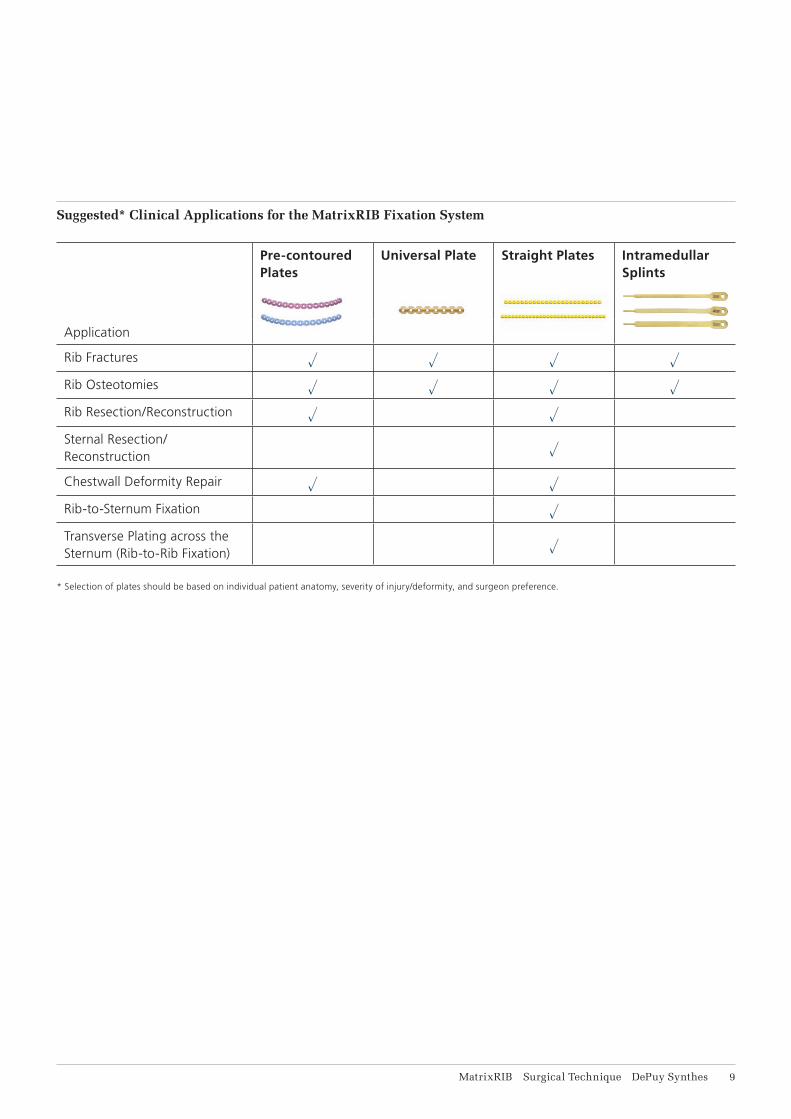
Suggested* Clinical Applications for the MatrixRIB Fixation System
Pre-contoured Plates
Universal Plate Straight Plates Intramedullar Splints
Application
Rib Fractures u u u u
Rib Osteotomies u u u u
Rib Resection/Reconstruction u u
Sternal Resection/ Reconstruction u
Chestwall Deformity Repair u u
Rib-to-Sternum Fixation u
Transverse Plating across the Sternum (Rib-to-Rib Fixation) u
* Selection of plates should be based on individual patient anatomy, severity of injury/deformity, and surgeon preference.
11 DePuy Synthes MatrixRIB Surgical Technique
General Adverse EventsAs with all major surgical procedures, risks, side effects and adverse events can occur. While many possible reac-tions may occur, some of the most common problems result from anesthesia and patient positioning (e.g. nausea, vomiting, dental injuries, neurological impair-ments, etc.), thrombosis, embolism, infection, nerve and/or tooth root damage or injury of other critical structures including blood vessels, excessive bleeding, damage to soft tissues incl. swelling, abnormal scar formation, func-tional impairment of the musculoskeletal system, pain, abnormal sensation due to the presence of the device, allergy or hyperreactions, side effects associated with hardware prominence, loosening, bending, or breakage of the device, mal-union, non-union or delayed union which may lead to breakage of the implant, reoperation.
Device Specific Adverse EventsDevice specific adverse events include but are not limited to:For chest wall reconstruction including spanning gaps:• Plate breakage• Pneumothorax • Loss of chest wall stability• Herniation• Postoperative dehiscence• Seroma • Bone Necrosis and partial skin necrosisFor chest wall deformities:• Residual or recurrent chest wall deformities • Pleural effusions• Seroma• Hematoma
Intended use, Indications, Contraindications, Warnings, and MRI Information

R8-9
R3
R4-5
R6-7
MatrixRIB Surgical Technique DePuy Synthes 11
FEATURES AND BENEFITS
MATRIXRIB
The DePuy Synthes MatrixRIB Fixation System consists of precontoured, shaped, and straight locking plates, locking screws, and intramedullary splints for the fi xation and stabilization of the chest wall.
• Designed to be used without removing periosteum to maximize blood supply to the bone
• All implants are manufactured from titanium alloy* or Pure Titanium for fl exibility and strength
• Drill bit with stop to prevent over-drilling • Self-retaining screwdriver blades
Straight locking plates• Straight plates for complex or custom bends
(24 or 30 holes)• Universal plate with eight holes
Locking screws• Screws work with self-retaining screwdriver blades to
reduce cam-out• Locking design for increased stable fi xation**• One screw diameter for use with all plates and splints
Locking holes
Longitudinal twist
In-plane radius
Right plates(red rose)
* Ti-6Al-7Nb** Mechanical test data on fi le at DePuy Synthes. Mechanical test results
may not necessarily be indicative of clinical performance.

L3
L4-5
L6-7
L8-9
12 DePuy Synthes MatrixRIB Surgical Technique
Precontoured locking plates• Plates are precontoured to fi t an average rib shape,
which minimizes intraoperative bending3 • Locking plate construct provides stable fi xation • Low-profi le 1.5 mm thick plates • Plates are color-coded to distinguish left and right
designs • Plates are etched on medial end to indicate the
corresponding rib curvature • A universal plate with 8 holes is available
Left plates(light blue)
Tubular radius
Out of plane radiusEtching
Intramedullary splints• Intramedullary splints allow less invasive procedures• Three widths available (3 mm, 4 mm, 5 mm)• Only one screw needed to secure splint
rib 3
rib 4
rib 5
rib 6
rib 7
rib 8
rib 9
rib 3
rib 4
rib 5
rib 6
rib 7
rib 8
rib 9
L6-7
L8-9
L3
L4-5R4-5
R6-7
R8-9
R3
MatrixRIB

MatrixRIB Surgical Technique DePuy Synthes 13
AO PRINCIPLES
In 1958, the AO formulated four basic principles, which have become the guidelines for internal fi xation.*
Anatomic reductionFracture reduction and fi xation to restore functional anatomical relationships.
Stable fixationStability by rigid fi xation or splintage, as the personality of the fracture and the injury requires.
Preservation of blood supplyPreservation of the blood supply to soft tissue and bone by careful handling and gentle reduction techniques.
Early, active mobilizationEarly and safe mobilization of the part and patient.
* M. E. Müller, M. Allgöwer, R. Schneider, and H. Willenegger. Manual of Internal Fixation, 3rd Edition. Berlin: Springer-Verlag. 1991.

14 DePuy Synthes MatrixRIB Surgical Technique
Position the patient to optimize access to the rib to be repaired.
A lateral thoracotomy may be used with the patient in a lateral decubitus position, and the arms abducted 90° on padded arm rests.
An anterolateral thoracotomy may be used with the patient in a supine position, with both arms abducted 90°.
PATIENT POSITIONING
MatrixRIB Surgical Technique DePuy Synthes 15
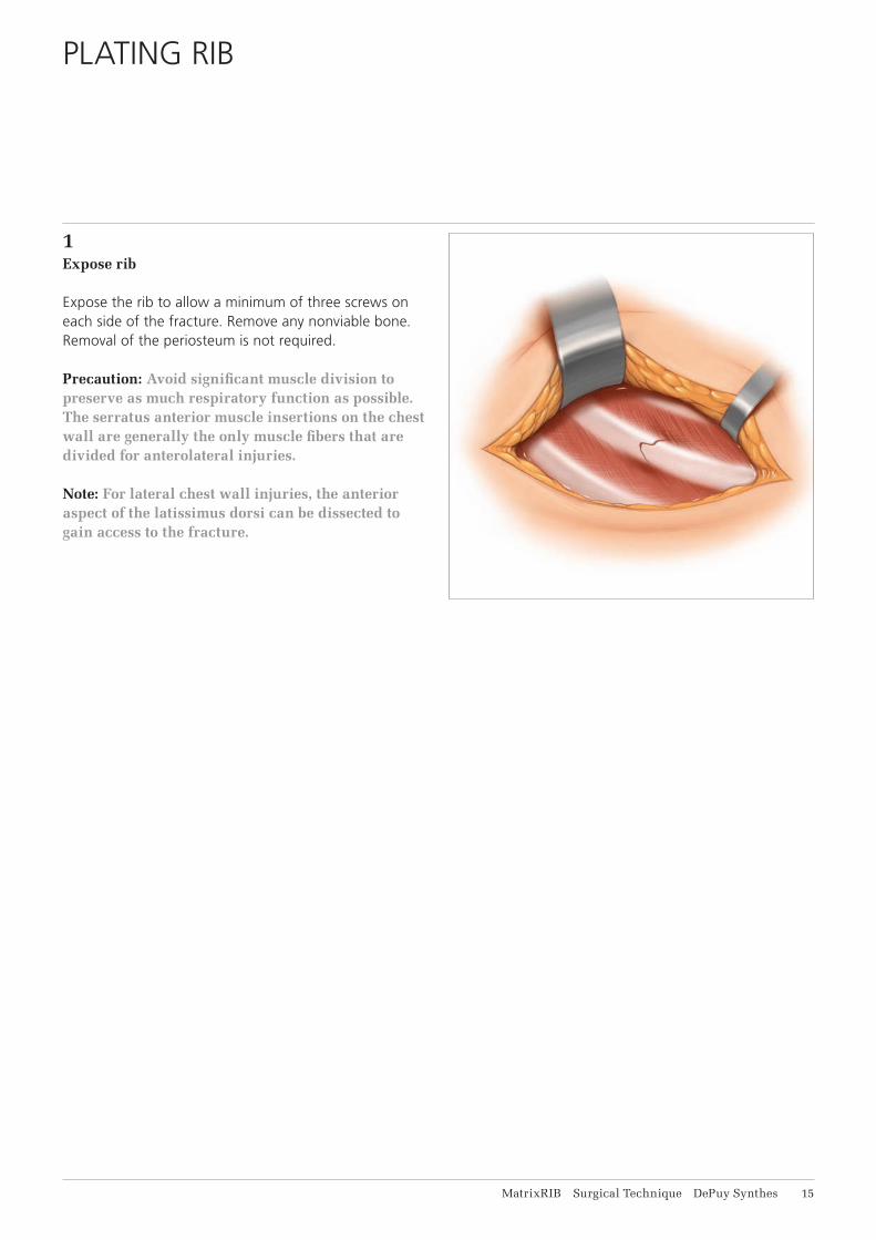
PLATING RIB
1Expose rib
Expose the rib to allow a minimum of three screws on each side of the fracture. Remove any nonviable bone. Removal of the periosteum is not required.
Precaution: Avoid significant muscle division to preserve as much respiratory function as possible. The serratus anterior muscle insertions on the chest wall are generally the only muscle fibers that are divided for anterolateral injuries.
Note: For lateral chest wall injuries, the anterior aspect of the latissimus dorsi can be dissected to gain access to the fracture.
16 DePuy Synthes MatrixRIB Surgical Technique
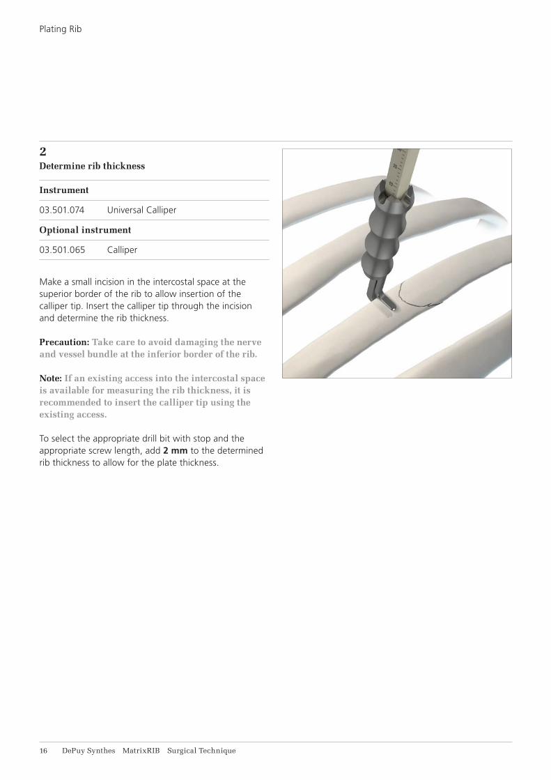
2Determine rib thickness
Instrument
03.501.074 Universal Calliper
Optional instrument
03.501.065 Calliper
Make a small incision in the intercostal space at the superior border of the rib to allow insertion of the calliper tip. Insert the calliper tip through the incision and determine the rib thickness.
Precaution: Take care to avoid damaging the nerve and vessel bundle at the inferior border of the rib.
Note: If an existing access into the intercostal space is available for measuring the rib thickness, it is recommended to insert the calliper tip using the exis ting access.
To select the appropriate drill bit with stop and the appropriate screw length, add 2 mm to the determined rib thickness to allow for the plate thickness.
Plating Rib
MatrixRIB Surgical Technique DePuy Synthes 17
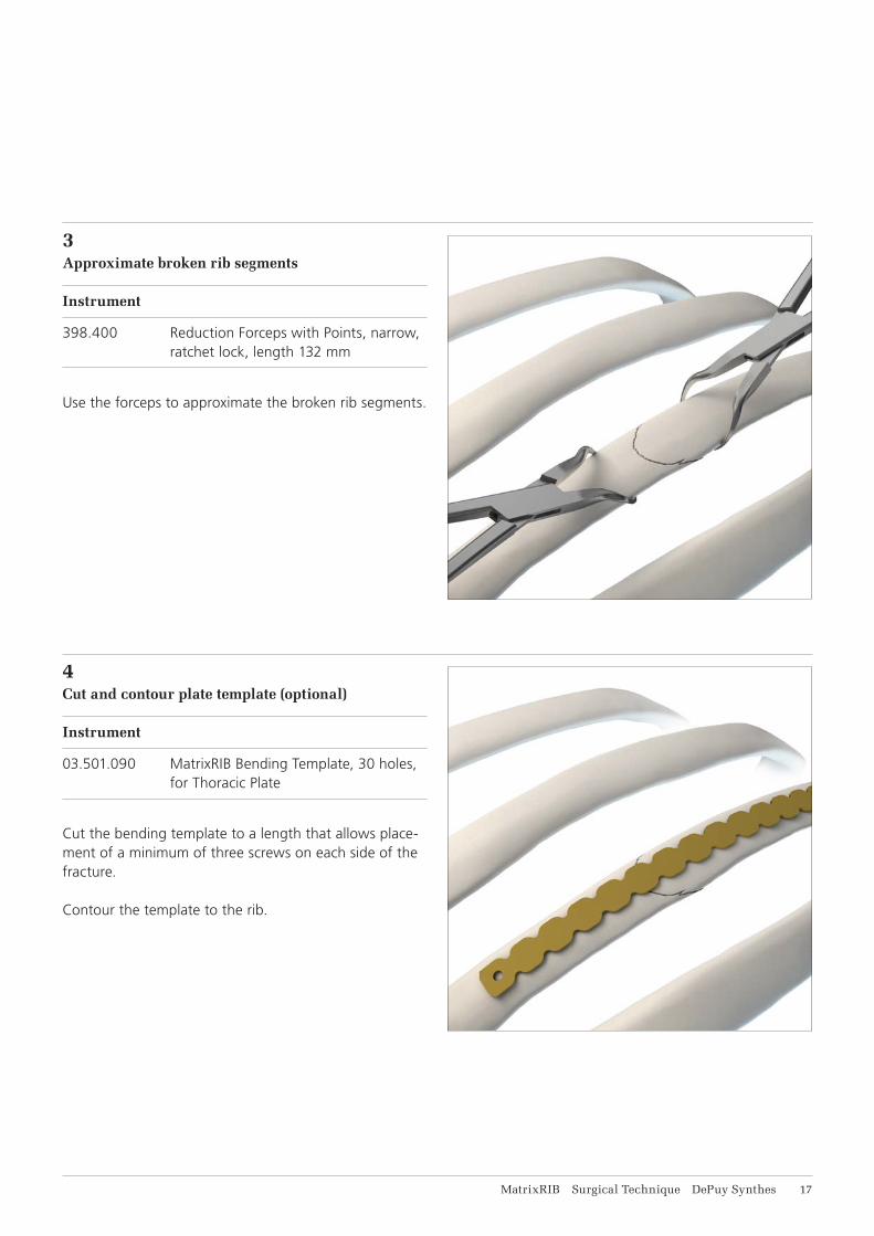
3Approximate broken rib segments
Instrument
398.400 Reduction Forceps with Points, narrow, ratchet lock, length 132 mm
Use the forceps to approximate the broken rib segments.
4Cut and contour plate template (optional)
Instrument
03.501.090 MatrixRIB Bending Template, 30 holes, for Thoracic Plate
Cut the bending template to a length that allows place-ment of a minimum of three screws on each side of the fracture.
Contour the template to the rib.

18 DePuy Synthes MatrixRIB Surgical Technique
5Select and cut plate (optional)
Instrument
03.503.057 Shortcut for MatrixMANDIBLE Plates, thickness 1.5 to 2.8, with RASP, required in pairs
Optional Instrument
391.990 Cutting Pliers for Plates and Rods
Use the bending template contoured in Step 4 to select the best matching plate.
Notes: • Position the precontoured plate with the etching
toward the sternum • A universal plate is available for use in place of a
precontoured plate (see Implants section) • Straight plates are available for use in place of a
precontoured plate (see Implants section)
If necessary, cut the plate to the desired length.
Precaution: Use a minimum of three screws on each side of the fracture, to properly secure the plate.
Plating Rib
MatrixRIB Surgical Technique DePuy Synthes 19
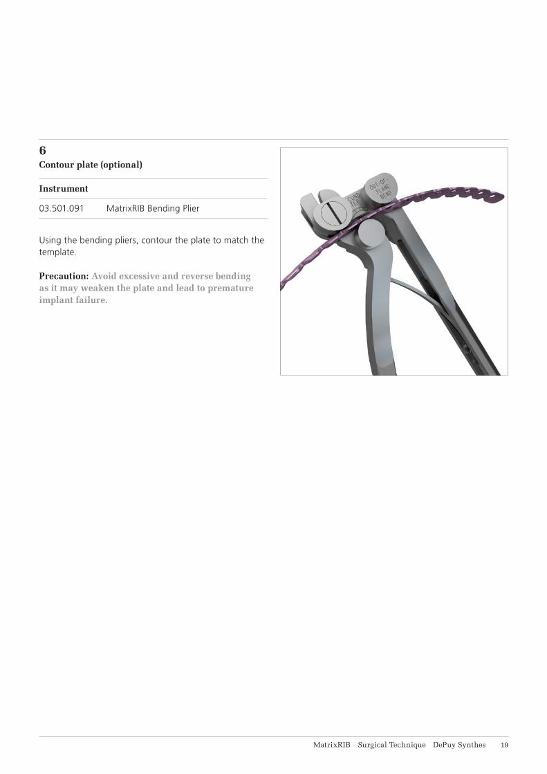
6Contour plate (optional)
Instrument
03.501.091 MatrixRIB Bending Plier
Using the bending pliers, contour the plate to match the template.
Precaution: Avoid excessive and reverse bending as it may weaken the plate and lead to premature implant failure.

21 DePuy Synthes MatrixRIB Surgical Technique
7Position plate
Instrument
03.501.071 MatrixRIB Plate Holding Forceps, small
Optional instruments
03.501.030 MatrixRIB Plate Holding Forceps, small, with ball tip
03.501.031 MatrixRIB Plate Holding Forceps, large, with ball tip
03.501.704 Threaded Reduction Tool for MatrixRIB, with AO Quick Coupling (see page 37 for instructions)
03.501.708 MatrixRIB Plate Holding Forceps, upright
03.501.709 MatrixRIB Plate Holding Forceps, large
Position the plate on the rib over the fracture, allowing a minimum of three screws on each side of the fracture.
Verify that the contour of the plate matches the rib.
Using the plate holding forceps, hold the plate on the rib.
Precaution: Insert the forceps from the superior border of the rib to avoid damaging the nerve and vessel bundle located at the inferior border of the rib.
Plating Rib

MatrixRIB Surgical Technique DePuy Synthes 21
8Drill
Instruments
03.501.033 MatrixRIB Drill Guide 2.2 for Plates
03.501.036– MatrixRIB Drill Bits 2.2 mm with Stop,03.501.050 length 135/6 mm to 20 mm, 2-flute, for J-Latch Coupling
Optional instruments
03.501.700 MatrixRIB Drill Guide, long
03.501.708 MatrixRIB Plate Holding Forceps, upright
03.501.709 MatrixRIB Plate Holding Forceps, large
Thread the drill guide into the plate. This will help ensure safe drilling and alignment of the drill hole with the plate hole.
Select the drill bit with stop as determined in Step 2 and drill.
Drill bits with stop are available with stop lengths rang-ing from 6 mm to 20 mm, in 2 mm increments, match-ing the locking screw lengths.
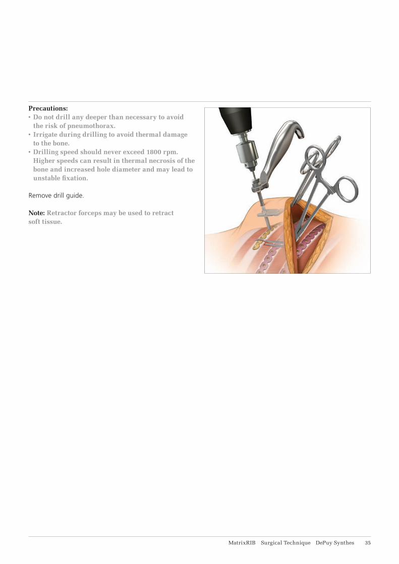
Precautions: • Do not drill any deeper than necessary, to avoid
the risk of pneumothorax.• Irrigate during drilling to avoid thermal damage
to the bone.• Drilling speed should never exceed 1800 rpm.
Higher speeds can result in thermal necrosis of the bone and increased hole diameter and may lead to unstable fixation.
Remove the 2.2 mm drill guide after drilling.
Options:• The MatrixRIB Trocar Instruments may be used
for drilling and screw insertion (see MatrixRIB Trocar Instruments instructions).
• The 90° Screwdriver for MatrixRIB System may be used for drilling (see 90° Screwdriver for MatrixRIB instructions).
22 DePuy Synthes MatrixRIB Surgical Technique
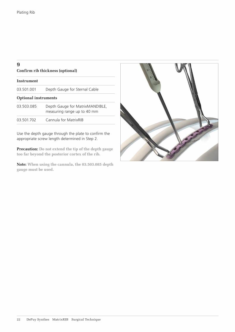
9Confirm rib thickness (optional)
Instrument
03.501.001 Depth Gauge for Sternal Cable
Optional instruments
03.503.085 Depth Gauge for MatrixMANDIBLE, measuring range up to 40 mm
03.501.702 Cannula for MatrixRIB
Use the depth gauge through the plate to confirm the appropriate screw length determined in Step 2.
Precaution: Do not extend the tip of the depth gauge too far beyond the posterior cortex of the rib.
Note: When using the cannula, the 03.503.085 depth gauge must be used.
Plating Rib

MatrixRIB Surgical Technique DePuy Synthes 23
10Select and insert screw
Instruments
03.503.071 Screwdriver Shaft MatrixMANDIBLE, medium, self-holding, for Hexagonal Coupling
311.023 Ratcheting Screwdriver Handle, with Hexagonal Coupling
Optional instrument
03.503.072 Screwdriver Shaft MatrixMANDIBLE, long, self-holding, for Hexagonal Coupling
Select and insert the locking screw (with proper length determined in Step 2) through the plate and tighten until secure. The screw length indicator on the module can be used to select the appropriate screws. 10 and 12 mm non-locking screws are available to ensure the plate sits flush with the bone.
Precautions:• The screw should be placed bicortically. The tip of
the screw should not extend too far beyond the posterior cortex to avoid deeper injury.
• In order to determine the appropriate amount of fixation for stability, the surgeon should consider the size and shape of the fracture or osteotomy. DePuy Synthes recommends at least three screws per plate per fracture side when repairing osteoto-mies and fractures with this system. Additional fixation is recommended to ensure stability of large fractures and osteotomies.
• The non-locking screws are for temporary fixation and will need to be replaced with locking screws before closure.
Note: • The MatrixRIB Trocar Instruments may be used
for screw insertion (see MatrixRIB Trocar Instru-ments instructions).
• The 90° Screwdriver for MatrixRIB System may be used for drilling (see 90° Screwdriver for MatrixRIB instructions).
24 DePuy Synthes MatrixRIB Surgical Technique
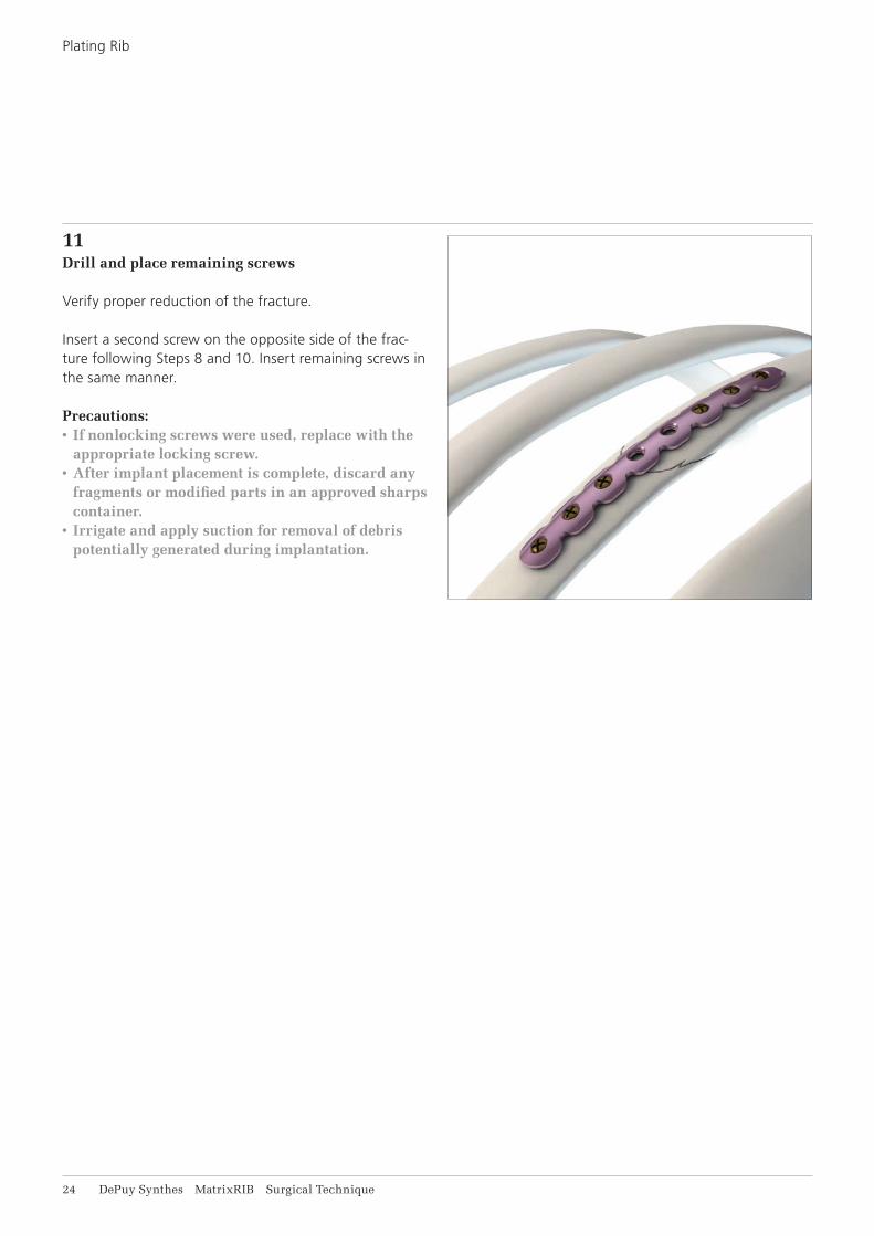
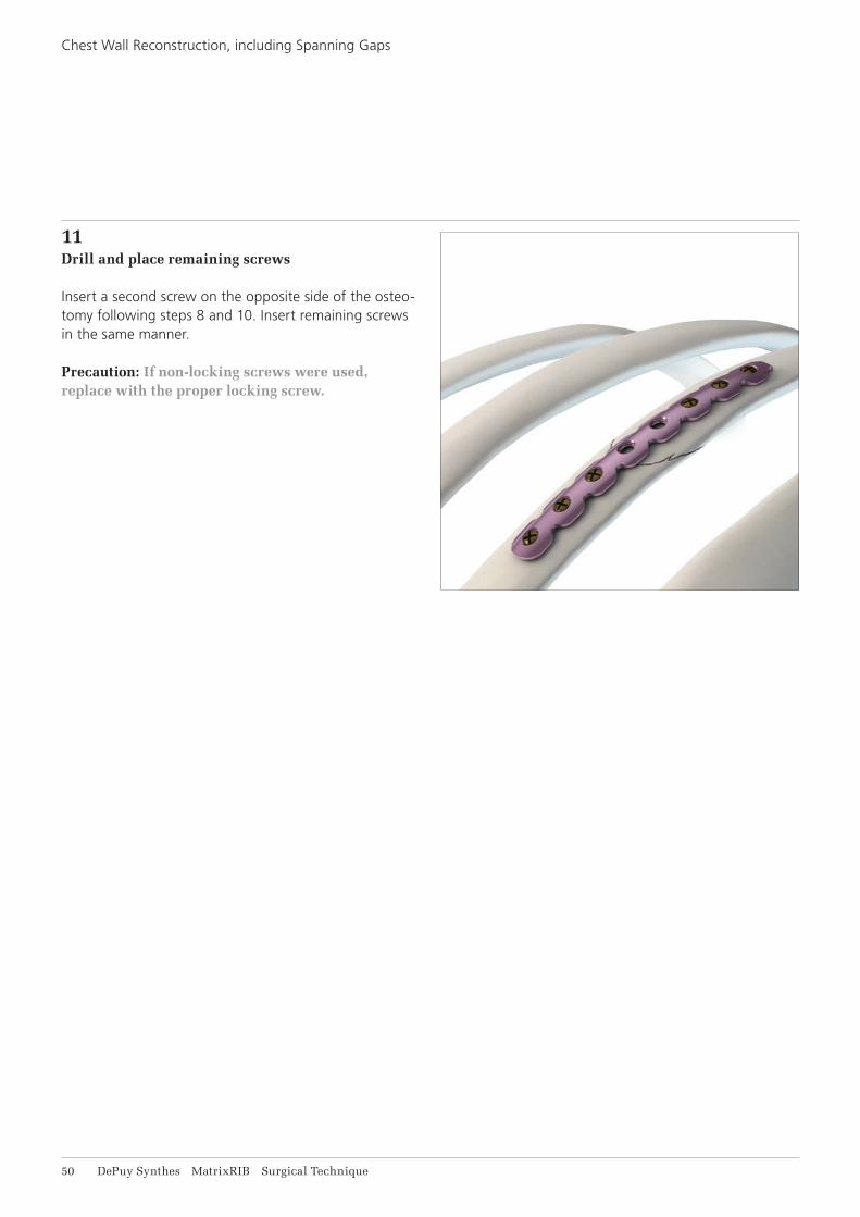
11Drill and place remaining screws
Verify proper reduction of the fracture.
Insert a second screw on the opposite side of the frac-ture following Steps 8 and 10. Insert remaining screws in the same manner.
Precautions:• If nonlocking screws were used, replace with the
appropriate locking screw.• After implant placement is complete, discard any
fragments or modified parts in an approved sharps container.
• Irrigate and apply suction for removal of debris potentially generated during implantation.
Plating Rib
MatrixRIB Surgical Technique DePuy Synthes 25
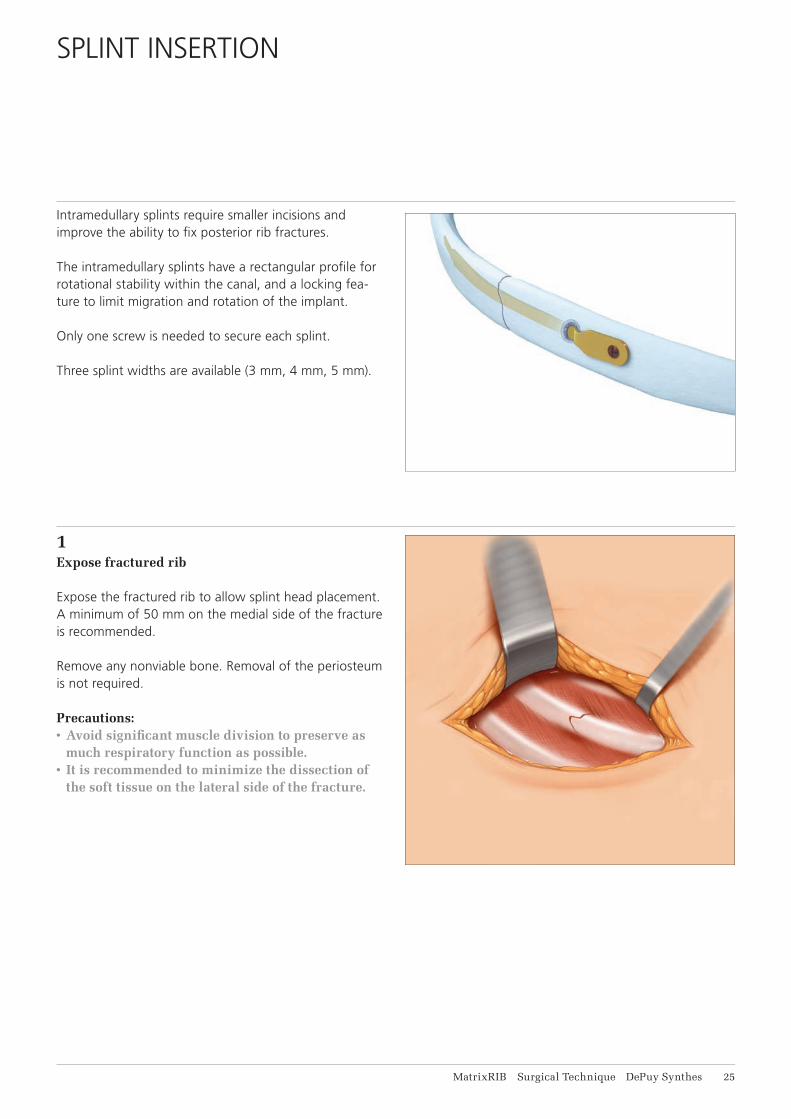
Intramedullary splints require smaller incisions and improve the ability to fi x posterior rib fractures.
The intramedullary splints have a rectangular profi le for rotational stability within the canal, and a locking fea-ture to limit migration and rotation of the implant.
Only one screw is needed to secure each splint.
Three splint widths are available (3 mm, 4 mm, 5 mm).
1Expose fractured rib
Expose the fractured rib to allow splint head placement. A minimum of 50 mm on the medial side of the fracture is recommended.
Remove any nonviable bone. Removal of the periosteum is not required.
Precautions: • Avoid signifi cant muscle division to preserve as
much respiratory function as possible.• It is recommended to minimize the dissection of
the soft tissue on the lateral side of the fracture.
SPLINT INSERTION
26 DePuy Synthes MatrixRIB Surgical Technique
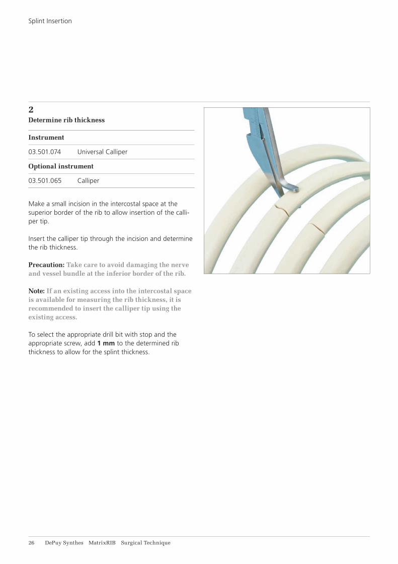
2Determine rib thickness
Instrument
03.501.074 Universal Calliper
Optional instrument
03.501.065 Calliper
Make a small incision in the intercostal space at the superior border of the rib to allow insertion of the calli-per tip.
Insert the calliper tip through the incision and determine the rib thickness.
Precaution: Take care to avoid damaging the nerve and vessel bundle at the inferior border of the rib.
Note: If an existing access into the intercostal space is available for measuring the rib thickness, it is recommended to insert the calliper tip using the exis ting access.
To select the appropriate drill bit with stop and the appropriate screw, add 1 mm to the determined rib thickness to allow for the splint thickness.
Splint Insertion

MatrixRIB Surgical Technique DePuy Synthes 27
3Prepare splint insertion hole
Instruments
03.501.055 MatrixRIB Drill Guide 5.5 for Intramedullary Splint Insertion
03.501.070 MatrixRIB Drill Bit 5.5 mm with Stop, length 125 mm, 2-fl ute, for J-Latch Coupling
03.501.071 MatrixRIB Plate Holding Forceps, small
Optional instruments
03.501.032 MatrixRIB Intramedullary Splint Driver
03.501.075 Drill Guide 5.5, for MatrixRIB Intramedullary Splints, without Handle
Insert the hook end of the drill guide into the intrame-dullary canal of the medial segment until it is seated fully on the rib.
Notes: • It is recommended to insert the hook near the
superior edge of the rib, and to drill an entry hole in the upper 2/3 of the rib.
• The small plate holding forceps can be used to hold the drill guide against the rib during drilling.
• The splint driver may be threaded into the drill guide to act as a handle, as needed.
Precautions: • If the drill guide without handle is used, ensure
the tapered end, labeled “Fracture”, is aligned with the fracture to ensure the hole is approxi-mately 30 mm from the fracture line.
• Ensure the lateral fracture segment is at least 5 cm long to accommodate the insertion length of the splint before drilling.
Ensure the medial end of the drill guide contacts the bone.
Using the 5.5 mm drill bit with stop, drill monocortically.
Remove the drill guide and verify the hole is approxi-mately 30 mm from the fracture line.
Precautions:• Irrigate during drilling to avoid thermal damage
to the bone.• Drilling speed should never exceed 1800 rpm.
Higher speeds can result in thermal necrosis of the bone and increased hole diameter and may lead to unstable fi xation.

28 DePuy Synthes MatrixRIB Surgical Technique
4Select splint
Instruments
03.501.032 MatrixRIB Intramedullary Splint Driver
03.501.061 MatrixRIB Template for Intramedullary Splint, small
03.501.062 MatrixRIB Template for Intramedullary Splint, medium
03.501.066 Mallet
398.400 Reduction Forceps with Points, narrow, ratchet lock, length 132 mm
The splint template is used to prepare the canal and select the correct size of splint. It is recommended to start with the small template before using the medium template.
Thread the splint driver into the splint template and insert the template into the insertion hole prepared in Step 3.
Remove the splint template.
Fully insert the template into the canal of the lateral fracture segment.
Remove the splint template.
Notes:• If the small template fi ts snugly, use the 3 mm wide
splint.• If the medium template fi ts snugly, use the 4 mm
wide splint.• If the medium template fi ts loosely, use the 5 mm
wide splint.• Use the mallet to assist insertion of the splint
template, if needed.
Use bone reduction forceps to hold the rib segment during splint template insertion.
Splint Insertion
MatrixRIB Surgical Technique DePuy Synthes 29
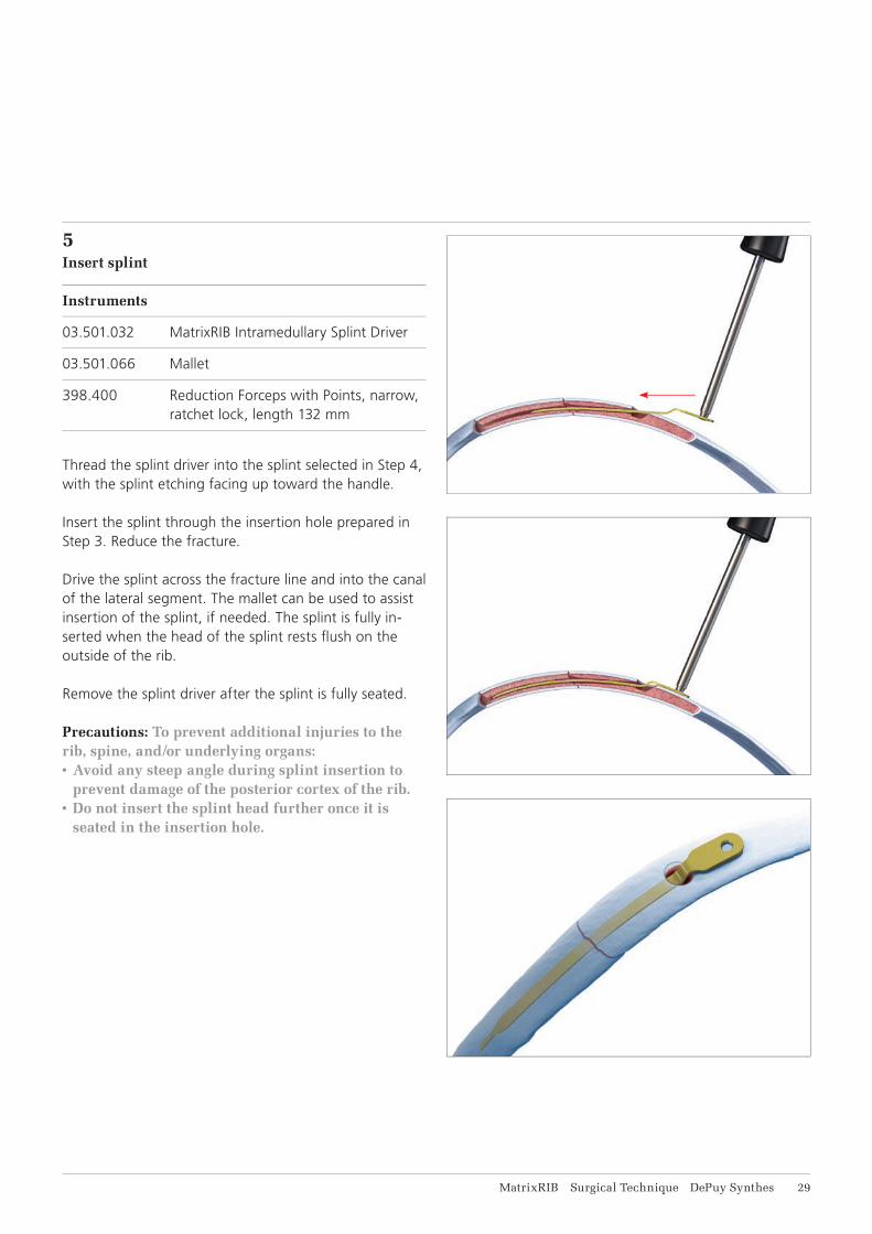
5Insert splint
Instruments
03.501.032 MatrixRIB Intramedullary Splint Driver
03.501.066 Mallet
398.400 Reduction Forceps with Points, narrow, ratchet lock, length 132 mm
Thread the splint driver into the splint selected in Step 4, with the splint etching facing up toward the handle.
Insert the splint through the insertion hole prepared in Step 3. Reduce the fracture.
Drive the splint across the fracture line and into the canal of the lateral segment. The mallet can be used to assist insertion of the splint, if needed. The splint is fully in-serted when the head of the splint rests fl ush on the outside of the rib.
Remove the splint driver after the splint is fully seated.
Precautions: To prevent additional injuries to the rib, spine, and/or underlying organs:• Avoid any steep angle during splint insertion to
prevent damage of the posterior cortex of the rib.• Do not insert the splint head further once it is
seated in the insertion hole.
31 DePuy Synthes MatrixRIB Surgical Technique
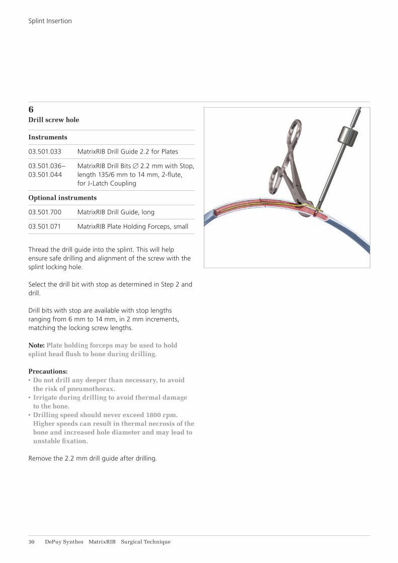
6Drill screw hole
Instruments
03.501.033 MatrixRIB Drill Guide 2.2 for Plates
03.501.036– MatrixRIB Drill Bits 2.2 mm with Stop, 03.501.044 length 135/6 mm to 14 mm, 2-flute,
for J-Latch Coupling
Optional instruments
03.501.700 MatrixRIB Drill Guide, long
03.501.071 MatrixRIB Plate Holding Forceps, small
Thread the drill guide into the splint. This will help ensure safe drilling and alignment of the screw with the splint locking hole.
Select the drill bit with stop as determined in Step 2 and drill.
Drill bits with stop are available with stop lengths ranging from 6 mm to 14 mm, in 2 mm increments, matching the locking screw lengths.
Note: Plate holding forceps may be used to hold splint head flush to bone during drilling.
Precautions:• Do not drill any deeper than necessary, to avoid
the risk of pneumothorax.• Irrigate during drilling to avoid thermal damage
to the bone.• Drilling speed should never exceed 1800 rpm.
Higher speeds can result in thermal necrosis of the bone and increased hole diameter and may lead to unstable fixation.
Remove the 2.2 mm drill guide after drilling.
Splint Insertion

MatrixRIB Surgical Technique DePuy Synthes 31
7Confirm rib thickness (optional)
Instrument
03.501.001 Depth Gauge for Sternal Cable
Optional instrument
03.503.085 Depth Gauge for MatrixMANDIBLE, measuring range up to 40 mm
Use the depth gauge through the splint to confirm the screw length determined in Step 2.
Precaution: Do not extend the tip of the depth gauge too far beyond the posterior cortex of the rib.
32 DePuy Synthes MatrixRIB Surgical Technique
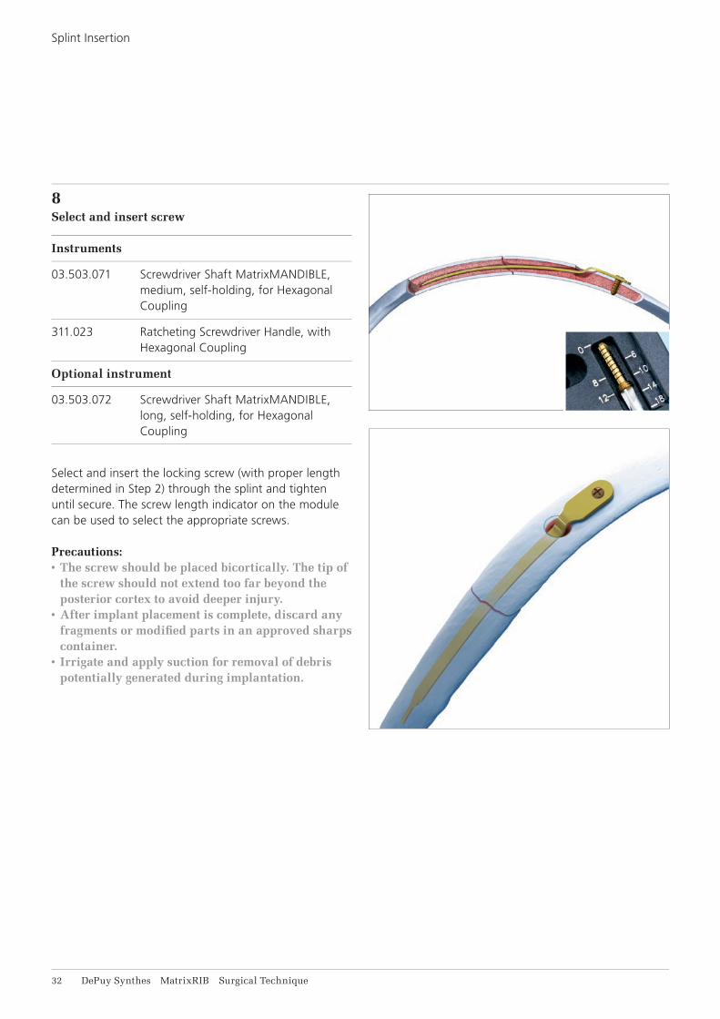
8Select and insert screw
Instruments
03.503.071 Screwdriver Shaft MatrixMANDIBLE, medium, self-holding, for Hexagonal Coupling
311.023 Ratcheting Screwdriver Handle, with Hexagonal Coupling
Optional instrument
03.503.072 Screwdriver Shaft MatrixMANDIBLE, long, self-holding, for Hexagonal Coupling
Select and insert the locking screw (with proper length determined in Step 2) through the splint and tighten until secure. The screw length indicator on the module can be used to select the appropriate screws.
Precautions:• The screw should be placed bicortically. The tip of
the screw should not extend too far beyond the posterior cortex to avoid deeper injury.
• After implant placement is complete, discard any fragments or modifi ed parts in an approved sharps container.
• Irrigate and apply suction for removal of debris potentially generated during implantation.
Splint Insertion

MatrixRIB Surgical Technique DePuy Synthes 33
The versatile MIPO instruments offer additional ap-proach options that are less invasive than the original MatrixRIB system. These instruments overcome various access challenges by extending their reach without increasing incision size. The instruments also enable rib stabilization of sub-scapula fractures with MatrixRIB implants.
The MIPO instrumentation includes the following: Trocar Instruments, Threaded Reduction Tool and instruments for the 90° Screwdriver.
MINIMALLY INVASIVE PLATE OSTEOSYNTHESIS (MIPO)
34 DePuy Synthes MatrixRIB Surgical Technique
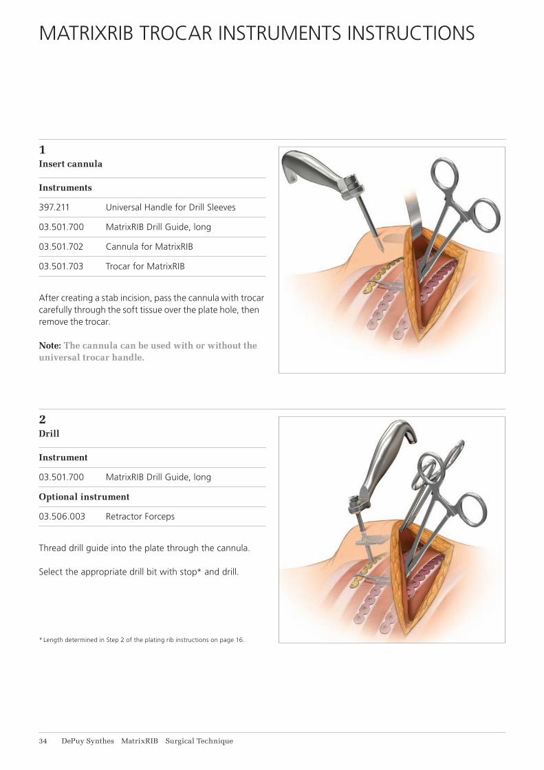
1Insert cannula
Instruments
397.211 Universal Handle for Drill Sleeves
03.501.700 MatrixRIB Drill Guide, long
03.501.702 Cannula for MatrixRIB
03.501.703 Trocar for MatrixRIB
After creating a stab incision, pass the cannula with trocar carefully through the soft tissue over the plate hole, then remove the trocar.
Note: The cannula can be used with or without the universal trocar handle.
MATRIXRIB TROCAR INSTRUMENTS INSTRUCTIONS
2Drill
Instrument
03.501.700 MatrixRIB Drill Guide, long
Optional instrument
03.506.003 Retractor Forceps
Thread drill guide into the plate through the cannula.
Select the appropriate drill bit with stop* and drill.
* Length determined in Step 2 of the plating rib instructions on page 16.
MatrixRIB Surgical Technique DePuy Synthes 35
Precautions:• Do not drill any deeper than necessary to avoid
the risk of pneumothorax.• Irrigate during drilling to avoid thermal damage
to the bone.• Drilling speed should never exceed 1800 rpm.
Higher speeds can result in thermal necrosis of the bone and increased hole diameter and may lead to unstable fixation.
Remove drill guide.
Note: Retractor forceps may be used to retract soft tissue.
36 DePuy Synthes MatrixRIB Surgical Technique
MatrixRIB Trocar Instruments Instructions
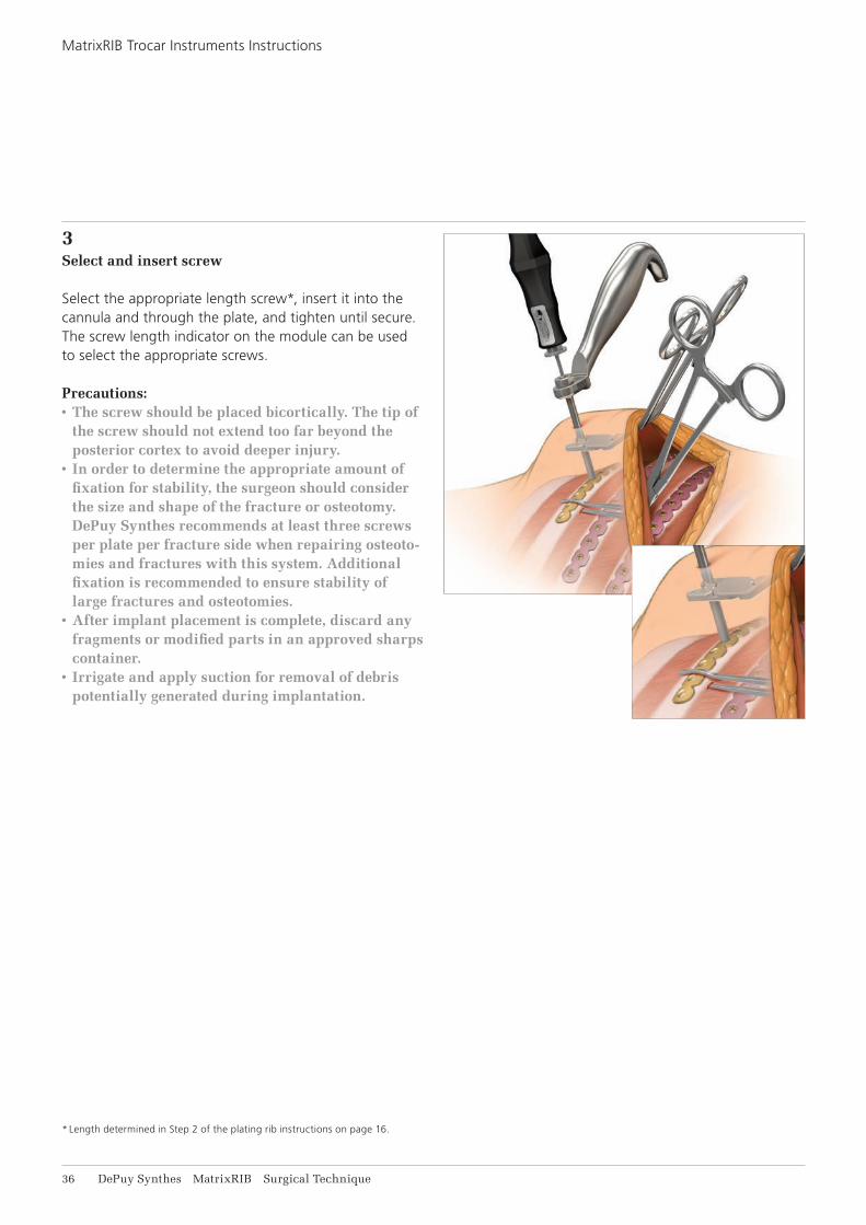
3Select and insert screw
Select the appropriate length screw*, insert it into the cannula and through the plate, and tighten until secure. The screw length indicator on the module can be used to select the appropriate screws.
Precautions: • The screw should be placed bicortically. The tip of
the screw should not extend too far beyond the posterior cortex to avoid deeper injury.
• In order to determine the appropriate amount of fixation for stability, the surgeon should consider the size and shape of the fracture or osteotomy. DePuy Synthes recommends at least three screws per plate per fracture side when repairing osteoto-mies and fractures with this system. Additional fixation is recommended to ensure stability of large fractures and osteotomies.
• After implant placement is complete, discard any fragments or modified parts in an approved sharps container.
• Irrigate and apply suction for removal of debris potentially generated during implantation.
* Length determined in Step 2 of the plating rib instructions on page 16.
MatrixRIB Surgical Technique DePuy Synthes 37
THREADED REDUCTION TOOL INSTRUCTIONS
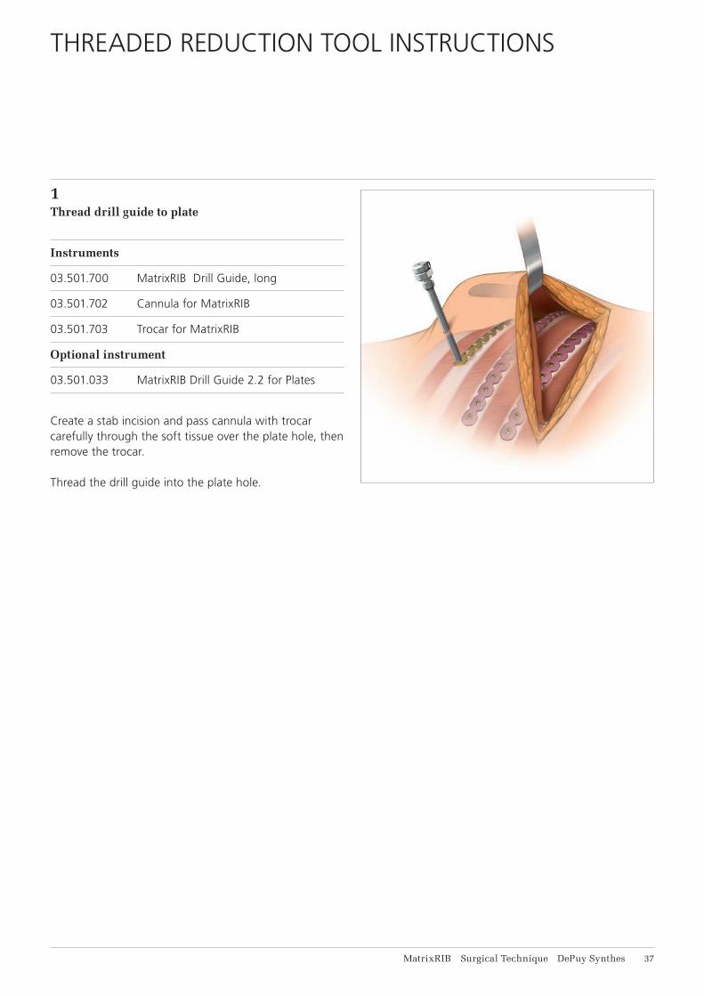
1Thread drill guide to plate
Instruments
03.501.700 MatrixRIB Drill Guide, long
03.501.702 Cannula for MatrixRIB
03.501.703 Trocar for MatrixRIB
Optional instrument
03.501.033 MatrixRIB Drill Guide 2.2 for Plates
Create a stab incision and pass cannula with trocar carefully through the soft tissue over the plate hole, then remove the trocar.
Thread the drill guide into the plate hole.
38 DePuy Synthes MatrixRIB Surgical Technique
2Insert Threaded Reduction Tool through drill guide
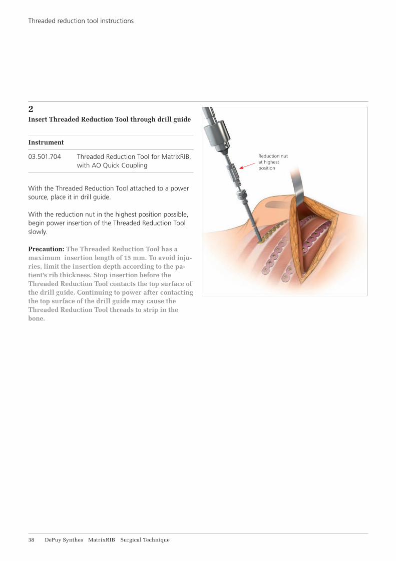
Instrument
03.501.704 Threaded Reduction Tool for MatrixRIB, with AO Quick Coupling
With the Threaded Reduction Tool attached to a power source, place it in drill guide.
With the reduction nut in the highest position possible, begin power insertion of the Threaded Reduction Tool slowly.
Precaution: The Threaded Reduction Tool has a maximum insertion length of 15 mm. To avoid inju-ries, limit the insertion depth according to the pa-tient's rib thickness. Stop insertion before the Threaded Reduction Tool contacts the top surface of the drill guide. Continuing to power after contacting the top surface of the drill guide may cause the Threaded Reduction Tool threads to strip in the bone.
Reduction nut at highest position
Threaded reduction tool instructions
MatrixRIB Surgical Technique DePuy Synthes 39
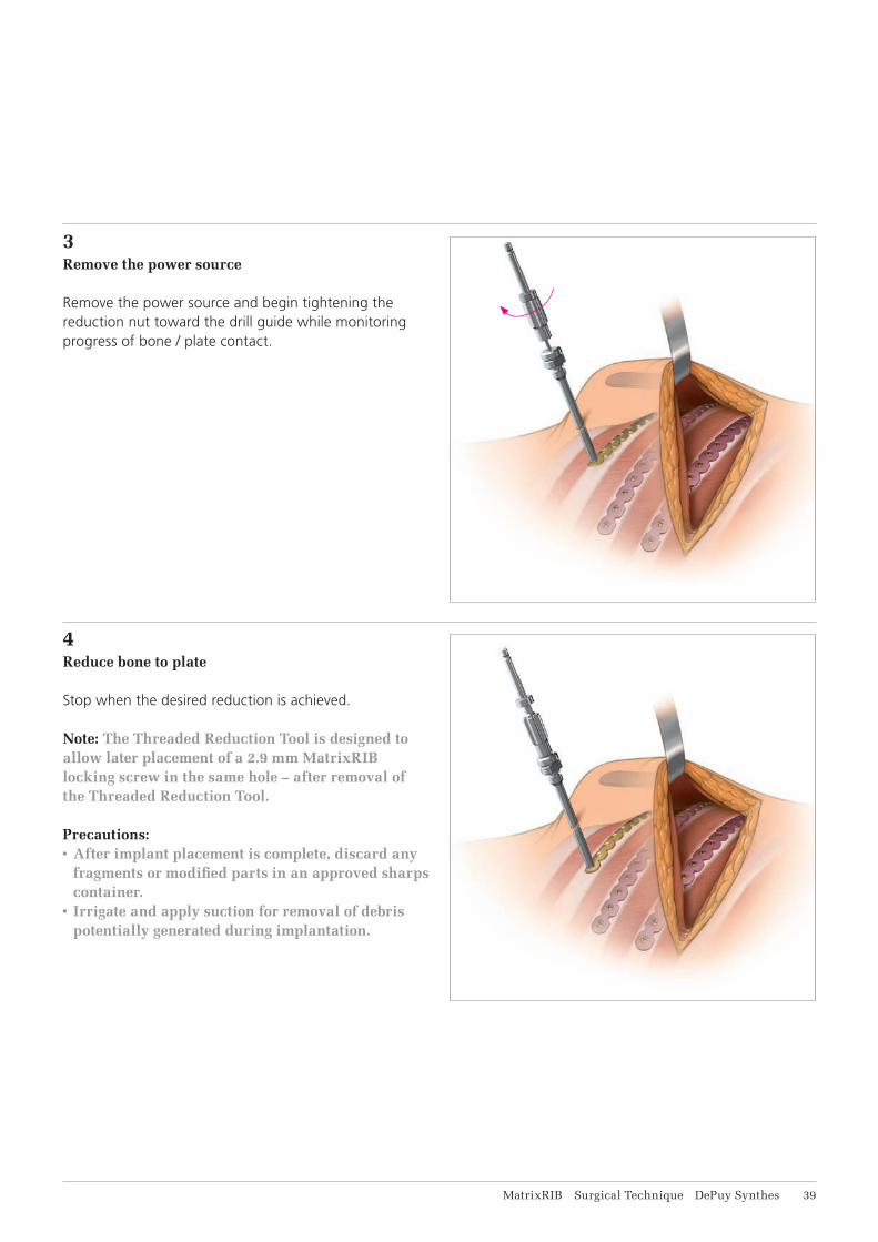
3Remove the power source
Remove the power source and begin tightening the reduction nut toward the drill guide while monitoring progress of bone / plate contact.
4Reduce bone to plate
Stop when the desired reduction is achieved.
Note: The Threaded Reduction Tool is designed to allow later placement of a 2.9 mm MatrixRIB locking screw in the same hole – after removal of the Threaded Reduction Tool.
Precautions:• After implant placement is complete, discard any
fragments or modified parts in an approved sharps container.
• Irrigate and apply suction for removal of debris potentially generated during implantation.

41 DePuy Synthes MatrixRIB Surgical Technique
1Drilling with 90° Screwdriver
Instruments
03.501.751 MatrixRIB Drill Guide 2.2 mm for Screwdriver 90° with 0°/90° angle
03.501.752 MatrixRIB Drill Guide 2.2, for Screwdriver 90° with 45°/45° angle
03.501.756 – MatrixRIB Drill Bit ⌀ 2.2 mm, with Stop,03.501.770 length 6 mm to 20 mm, 2-fl ute, for Screwdriver 90°
Engage and hold the desired angle drill guide on the desired angle plate hole.
Note: Ensure the head of the drill guide is seated fl at on top of the plate to ensure proper engagement.
Select the appropriate drill bit with stop* and drill. The drill bit length indicator on the side of the 90° screw-driver module can be used to reconfi rm the length of the drill bit.
Precautions:• Do not drill any deeper than necessary to avoid
the risk of pneumothorax.• Irrigate during drilling to avoid thermal damage
to the bone.• Drilling speed should never exceed 1800 rpm.
Higher speeds can result in thermal necrosis of the bone and increased hole diameter and may lead to unstable fi xation.
Remove drill guide after drilling.
Note: 90° Screwdriver may stall during drilling if drill bit is misaligned with the drill guide.
* Length determined in Step 2 of the plating rib instructions on page 16.
90° SCREWDRIVER FOR MATRIXRIB SYSTEM INSTRUCTIONS

MatrixRIB Surgical Technique DePuy Synthes 41
2 Insert screw
Instrument
03.501.750 MatrixRIB Screwdriver Blade, self- holding, for Screwdriver 90°
Select the appropriate length screw*, insert it through the plate and tighten until secure. Screw length can be determined using the screw length indication on the module.
Precautions:• The screw should be placed bicortically. The tip of
the screw should not extend too far beyond the posterior cortex to avoid deeper injury.
• After implant placement is complete, discard any fragments or modifi ed parts in an approved sharps container.
• Irrigate and apply suction for removal of debris potentially generated during implantation.
* Length determined in Step 2 of the plating rib instructions on page 16.

42 DePuy Synthes MatrixRIB Surgical Technique
CHEST WALL RECONSTRUCTION, INCLUDING SPANNING GAPS
1 Position patient
Position the patient to optimize access to the chest wall region to be reconstructed.
2Expose surgical site
Incise and elevate soft tissues as required to gain access to the surgical site.
Excise non-viable soft tissues and boney structures. Ensure enough viable bone is available for a minimum of three screws on either side of the osteotomy.
Warning: The surgeon should consider additional surgical methods to reduce the potential for adhe-sion and/or herniation when implants are used to bridge gaps after chest wall resections.
MatrixRIB Surgical Technique DePuy Synthes 43
3 Determine rib/sternal thickness
Instrument
03.501.074 Universal Calliper
Optional instrument
03.501.065 Calliper
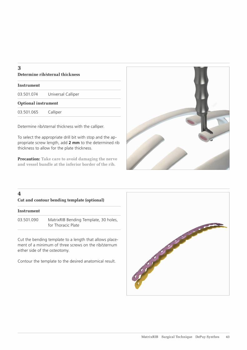
Determine rib/sternal thickness with the calliper.
To select the appropriate drill bit with stop and the ap-propriate screw length, add 2 mm to the determined rib thickness to allow for the plate thickness.
Precaution: Take care to avoid damaging the nerve and vessel bundle at the inferior border of the rib.
4Cut and contour bending template (optional)
Instrument
03.501.090 MatrixRIB Bending Template, 30 holes, for Thoracic Plate
Cut the bending template to a length that allows place-ment of a minimum of three screws on the rib/sternum either side of the osteotomy.
Contour the template to the desired anatomical result.

44 DePuy Synthes MatrixRIB Surgical Technique
5 Select and cut plate (optional)
Instrument
03.503.057 Shortcut for MatrixMANDIBLE Plates, thickness 1.5 to 2.8, with Rasp. required in pairs
Use the plate template contoured in Step 4 to select the best matching plate.
Note: Position the precontoured plate with the etching toward the sternum.
If necessary, cut the plate to the desired length.
Precaution: In order to determine the appropriate amount of fixation for stability, the surgeon should consider the size and shape of the fracture or osteo-tomy. DePuy Synthes recommends at least three screws per plate per fracture side when repairing osteotomies and fractures with this system. Addi-tional fixation is recommended to ensure stability of large fractures and osteotomies.
Chest Wall Reconstruction, including Spanning Gaps

MatrixRIB Surgical Technique DePuy Synthes 45
6Contour plate (optional)
Instrument
03.501.091 MatrixRIB Bending Plier
Using the bending pliers, contour the plate to match the template.
Precaution: Avoid excessive and reverse bending as it may weaken the plate and lead to premature im-plant failure.
46 DePuy Synthes MatrixRIB Surgical Technique
7Position plate
Instrument
03.501.071 MatrixRIB Plate Holding Forceps, small
Optional instruments
03.501.030 MatrixRIB Plate Holding Forceps, small, with ball tip
03.501.031 MatrixRIB Plate Holding Forceps, large, with ball tip
03.501.704 Threaded Reduction Tool for MatrixRIB, with AO Quick Coupling (see page 37 for instructions)
03.501.708 MatrixRIB Plate Holding Forceps, upright
03.501.709 MatrixRIB Plate Holding Forceps, large
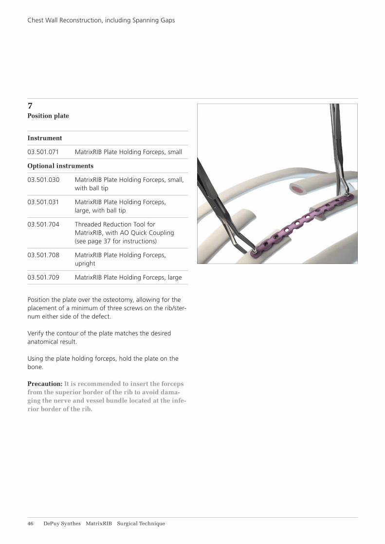
Position the plate over the osteotomy, allowing for theplacement of a minimum of three screws on the rib/ster-num either side of the defect.
Verify the contour of the plate matches the desired anatomical result.
Using the plate holding forceps, hold the plate on thebone.
Precaution: It is recommended to insert the forceps from the superior border of the rib to avoid dama-ging the nerve and vessel bundle located at the infe-rior border of the rib.
Chest Wall Reconstruction, including Spanning Gaps
MatrixRIB Surgical Technique DePuy Synthes 47
8Drill
Instruments
03.501.033 MatrixRIB Drill Guide 2.2 for Plates
03.501.036 – MatrixRIB Drill Bits ⌀ 2.2 mm with Stop,03.501.050 length 135/6 mm to 20 mm, 2-flute, for J-Latch Coupling
Optional instruments
03.501.700 MatrixRIB Drill Guide, long
03.501.708 MatrixRIB Plate Holding Forceps, upright
03.501.709 MatrixRIB Plate Holding Forceps, large
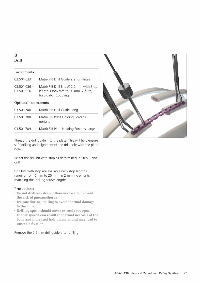
Thread the drill guide into the plate. This will help ensure safe drilling and alignment of the drill hole with the plate hole.
Select the drill bit with stop as determined in Step 3 and drill.
Drill bits with stop are available with stop lengths ranging from 6 mm to 20 mm, in 2 mm increments, matching the locking screw lengths.
Precautions:• Do not drill any deeper than necessary, to avoid
the risk of pneumothorax.• Irrigate during drilling to avoid thermal damage
to the bone.• Drilling speed should never exceed 1800 rpm.
Higher speeds can result in thermal necrosis of the bone and increased hole diameter and may lead to unstable fixation.
Remove the 2.2 mm drill guide after drilling.

48 DePuy Synthes MatrixRIB Surgical Technique
9Confirm rib/sternal thickness (optional)
Instrument
03.501.001 Depth Gauge for Sternal Cable
Optional instruments
03.503.085 Depth Gauge for MatrixMANDIBLE, measuring range up to 40 mm
03.501.702 Cannula for MatrixRIB
Use the depth gauge through the plate to confirm the appropriate screw length determined in Step 3.
Precaution: Do not extend the tip of the depth gauge too far beyond the posterior cortex of the rib.
Note: When using the cannula, the 03.503.085 depth gauge must be used.
Chest Wall Reconstruction, including Spanning Gaps

MatrixRIB Surgical Technique DePuy Synthes 49
10Select and insert screw
Instruments
03.503.071 Screwdriver Shaft MatrixMANDIBLE, medium, self-holding, for Hexagonal Coupling
311.023 Ratcheting Screwdriver Handle, with Hexagonal Coupling
Optional instrument
03.503.072 Screwdriver Shaft MatrixMANDIBLE, long, self-holding, for Hexagonal Coupling
Select and insert the locking screw (with proper length determined in Step 3) through the plate and tighten until secure. The screw length indicator on the module can be used to select the appropriate screws. 10 and 12 mm non-locking screws are available to ensure the plate sits flush with the bone.
Precautions:• The screw should be placed bicortically. The tip of
the screw should not extend too far beyond the posterior cortex to avoid deeper injury.
• In order to determine the appropriate amount of fixation for stability, the surgeon should consider the size and shape of the fracture or osteotomy. DePuy Synthes recommends at least three screws per plate per fracture side when repairing osteoto-mies and fractures with this system. Additional fixation is recommended to ensure stability of large fractures and osteotomies.
• The non-locking screws are for temporary fixation and will need to be replaced with locking screws before closure.
Note: • The MatrixRIB Trocar Instruments may be used
for screw insertion (see MatrixRIB Trocar Instru-ments instructions on page 34).
• The 90° Screwdriver for MatrixRIB System may be used for drilling (see 90° Screwdriver for MatrixRIB instructions on page 40).
51 DePuy Synthes MatrixRIB Surgical Technique
Chest Wall Reconstruction, including Spanning Gaps
11Drill and place remaining screws
Insert a second screw on the opposite side of the osteo-tomy following steps 8 and 10. Insert remaining screws in the same manner.
Precaution: If non-locking screws were used, replace with the proper locking screw.

MatrixRIB Surgical Technique DePuy Synthes 51
12Insert remaining plates (optional)
Insert remaining plates as per steps 3 through 11.
A minimum of three long MatrixRIB straight plates (24 or 30 holes) is recommended for transverse sternal reconstruction.In order to determine the appropriate amount of fixation for stability, the surgeon should consider the size and shape of the fracture or osteotomy. DePuy Synthes recommends at least three screws per plate per fracture side when repairing osteotomies and fractures with this system. Additional fixation is recommended to ensure stability of large fractures and osteotomies.
Precautions:• After implant placement is complete, discard any
fragments or modified parts in an approved sharps container.
• Irrigate and apply suction for removal of debris potentially generated during implantation.

52 DePuy Synthes MatrixRIB Surgical Technique
13Post-Operative Considerations
Avoid pulling or lifting the patient by the arms for six weeks.
Avoid raising arms higher than 90° at shoulder level.
Chest Wall Reconstruction, including Spanning Gaps
MatrixRIB Surgical Technique DePuy Synthes 53
CHEST WALL DEFORMITY REPAIR
1Position patient
Position the patient with the arms tucked along the sides to optimize access to the chest wall region to be re-paired. Avoid placing arms at 90° on arm boards, as this makes the chest closure more difficult.
2Expose surgical site
Incise and elevate soft tissues as required to gain access to the surgical site.
54 DePuy Synthes MatrixRIB Surgical Technique
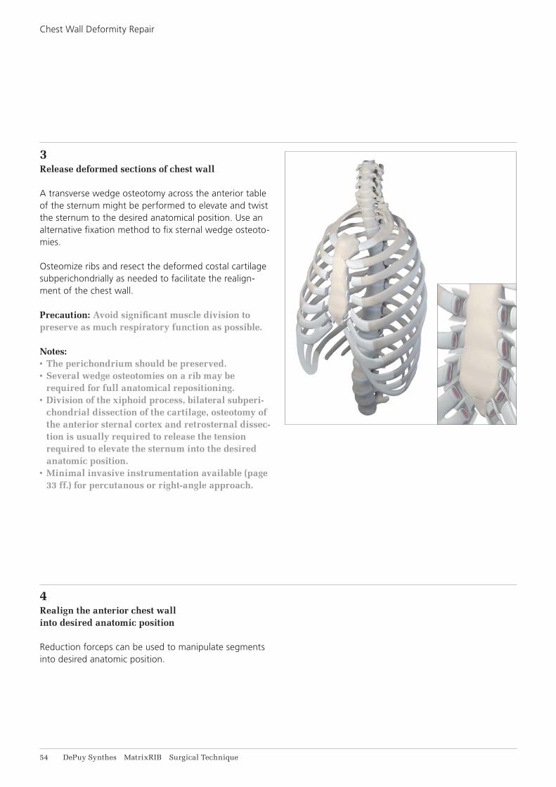
3Release deformed sections of chest wall
A transverse wedge osteotomy across the anterior table of the sternum might be performed to elevate and twist the sternum to the desired anatomical position. Use an alternative fixation method to fix sternal wedge osteoto-mies.
Osteomize ribs and resect the deformed costal cartilagesubperichondrially as needed to facilitate the realign-ment of the chest wall.
Precaution: Avoid significant muscle division to preserve as much respiratory function as possible.
Notes:• The perichondrium should be preserved. • Several wedge osteotomies on a rib may be
required for full anatomical repositioning.• Division of the xiphoid process, bilateral subperi-
chondrial dissection of the cartilage, osteotomy of the anterior sternal cortex and retrosternal dissec-tion is usually required to release the tension required to elevate the sternum into the desired anatomic position.
• Minimal invasive instrumentation available (page 33 ff.) for percutanous or right-angle approach.
4Realign the anterior chest wallinto desired anatomic position
Reduction forceps can be used to manipulate segments into desired anatomic position.
Chest Wall Deformity Repair
MatrixRIB Surgical Technique DePuy Synthes 55
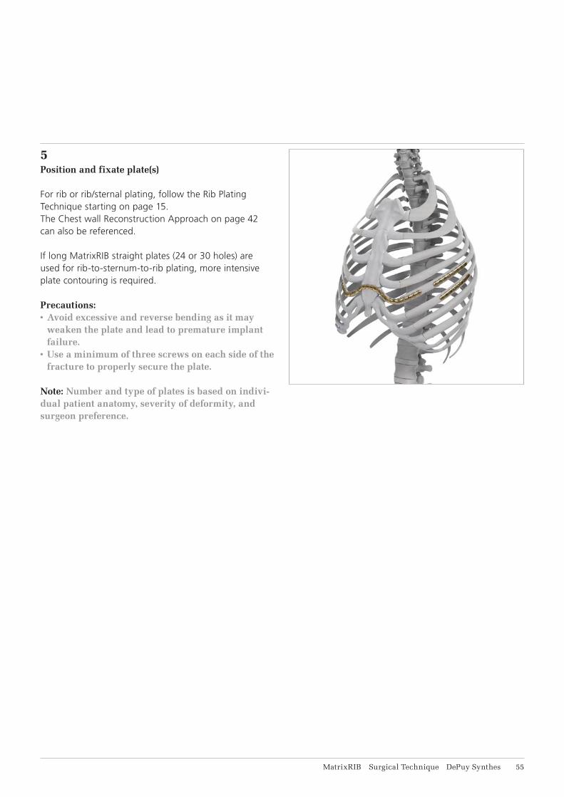
5Position and fixate plate(s)
For rib or rib/sternal plating, follow the Rib Plating Technique starting on page 15. The Chest wall Reconstruction Approach on page 42 can also be referenced.
If long MatrixRIB straight plates (24 or 30 holes) are used for rib-to-sternum-to-rib plating, more intensive plate contouring is required.
Precautions:• Avoid excessive and reverse bending as it may
weaken the plate and lead to premature implant failure.
• Use a minimum of three screws on each side of the fracture to properly secure the plate.
Note: Number and type of plates is based on indivi-dual patient anatomy, severity of deformity, and surgeon preference.
56 DePuy Synthes MatrixRIB Surgical Technique
6Post-Operative Considerations
Avoid pulling or lifting the patient by the arms for six weeks.
Avoid raising arms higher than 90° at shoulder level.
Avoid contact sports and other activities for which there is the potential for a high-velocity impact.
Chest Wall Deformity Repair
MatrixRIB Surgical Technique DePuy Synthes 57
IMPLANTS
MatrixRIB pre contoured Plates, Titanium Alloy (TAN)*,***
04.501.001 15 holes, for left rib 3 04.501.002 15 holes, for right rib 3 04.501.003 16 holes, for left ribs 4 and 5 04.501.004 16 holes, for right ribs 4 and 5 04.501.005 17 holes, for left ribs 6 and 7 04.501.006 17 holes, for right ribs 6 and 7 04.501.007 18 holes, for left ribs 8 and 9 04.501.008 18 holes, for right ribs 8 and 9
04.501.009 MatrixRIB Universal Plate, 8 holes, Titanium Alloy (TAN)*,***
MatrixRIB Straight Plates, Titanium Alloy (TAN)*,***
04.501.096 24 holes, 240 mm length04.501.097 30 holes, 300 mm length
MatrixRIB Intramedullary Splints, Titanium Alloy (TAN)*,***
04.501.010 Small, 3 mm width 04.501.011 Medium, 4 mm width 04.501.012 Large, 5 mm width
MatrixRIB LOCK Screws 2.9 mm, self-tapping,Titanium Alloy (TAN)* (in 2 mm increments)**
04.501.016.01– 6–20 mm04.501.030.01
MatrixRIB NON-LOCK Screws 2.9 mm, self-tapping,Titanium Alloy (TAN)*,**
04.501.040.01 10 mm04.501.042.01 12 mm
* Ti-6Al-7Nb ** For a pack of 5 add suffix «.05»; for sterile screws add suffix «.01S»
*** For sterile plates add suffix «S»
Right plate (rose red) 04.501.002
Left plate (light blue) 04.501.001
58 DePuy Synthes MatrixRIB Surgical Technique
INSTRUMENTS
03.503.085 Depth Gauge for MatrixMANDIBLE, measuring range up to 40 mm
03.501.030 MatrixRIB Plate Holding Forceps, small, with ball tip
03.501.031 MatrixRIB Plate Holding Forceps, large, with ball tip
03.501.032 MatrixRIB Intramedullary Splint Driver
03.501.036– MatrixRIB Drill Bits 2.2 mm with Stop,03.501.050 length 135/6 mm to 20 mm, 2-fl ute, for J-Latch Coupling
03.501.033 MatrixRIB Drill Guide 2.2 for Plates
MatrixRIB Surgical Technique DePuy Synthes 59
03.501.055 MatrixRIB Drill Guide 5.5 for Intramedullary Splint Insertion
03.501.061 MatrixRIB Template for Intramedullary Splint, small
03.501.062 MatrixRIB Template for Intramedullary Splint, medium
03.501.066 Mallet
03.501.070 MatrixRIB Drill Bit 5.5 mm with Stop, length 125 mm, 2-fl ute, for J-Latch Coupling*
03.501.065 Calliper
* For sterile drill bits add suffi x “S”
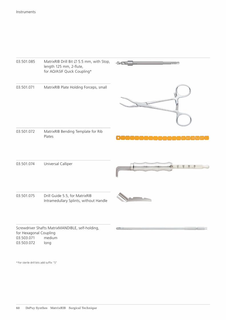
61 DePuy Synthes MatrixRIB Surgical Technique
03.501.071 MatrixRIB Plate Holding Forceps, small
03.501.072 MatrixRIB Bending Template for Rib Plates
03.501.074 Universal Calliper
03.501.075 Drill Guide 5.5, for MatrixRIB Intramedullary Splints, without Handle
Screwdriver Shafts MatrixMANDIBLE, self-holding, for Hexagonal Coupling03.503.071 medium03.503.072 long
* For sterile drill bits add suffi x “S”
03.501.085 MatrixRIB Drill Bit 5.5 mm, with Stop, length 125 mm, 2-fl ute, for AO/ASIF Quick Coupling*
Instruments

MatrixRIB Surgical Technique DePuy Synthes 61
311.023 Ratcheting Screwdriver Handle, with Hexagonal Coupling
03.501.091 MatrixRIB Bending Plier
03.503.057 Shortcut for MatrixMANDIBLE Plates, thickness 1.5 to 2.8, with RASP, required in pairs
398.400 Reduction Forceps with Points, narrow, ratchet lock, length 132 mm
397.211 Universal Handle for Drill Sleeves
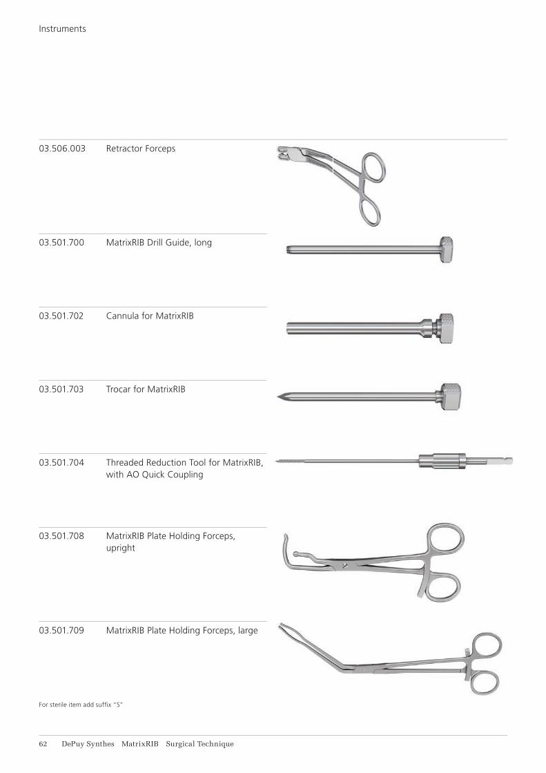
62 DePuy Synthes MatrixRIB Surgical Technique
03.506.003 Retractor Forceps
03.501.700 MatrixRIB Drill Guide, long
03.501.702 Cannula for MatrixRIB
03.501.703 Trocar for MatrixRIB
03.501.704 Threaded Reduction Tool for MatrixRIB, with AO Quick Coupling
03.501.708 MatrixRIB Plate Holding Forceps, upright
03.501.709 MatrixRIB Plate Holding Forceps, large
For sterile item add suffi x “S”
Instruments
MatrixRIB Surgical Technique DePuy Synthes 63
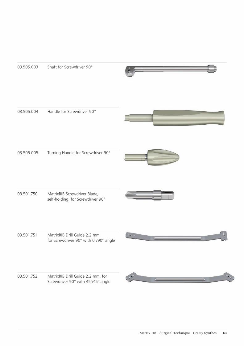
03.505.003 Shaft for Screwdriver 90°
03.505.004 Handle for Screwdriver 90°
03.505.005 Turning Handle for Screwdriver 90°
03.501.750 MatrixRIB Screwdriver Blade, self-holding, for Screwdriver 90°
03.501.751 MatrixRIB Drill Guide 2.2 mm for Screwdriver 90° with 0°/90° angle
03.501.752 MatrixRIB Drill Guide 2.2 mm, for Screwdriver 90° with 45°/45° angle

64 DePuy Synthes MatrixRIB Surgical Technique
03.501.756 length 6 mm
03.501.758 lengths 8 mm
03.501.760 length 10 mm
03.501.762 length 12 mm
03.501.764 length 14 mm
03.501.766 length 16 mm
03.501.767 length 18 mm
03.501.770 length 20 mm
MatrixRIB Drill Bits* 2.2 mm, with Stop, 2-fl ute,for Screwdriver 90°
391.990 Cutting Pliers for Plates and Rods
03.503.085 Depth Gauge for MatrixMANDIBLE, measuring range up to 40 mm
* For sterile drill bits add suffi x “S”
Instruments

MatrixRIB Surgical Technique DePuy Synthes 65
REFERENCES
1 Tanaka H, Yukioka T, Yamaguti Y, Shimizu S, Goto H, Matsuda H, Shimazaki S. Surgical stabilization of inter-nal pneumatic stabilization? A prospective randomized study of management of severe flail chest patients. J Trauma. 2002 Apr;52(4):727-32; discussion 732.
2 Balci AE, Eren S, Cakir O, Eren MN. Open fixation in
flail chest: review of 64 patients. Asian Cardiovasc Thorac Ann. 2004 Mar;12(1):11-5.
3 Mohr M, Abrams E, Engel C, et al. Geometry of human ribs pertinent to orthopedic chest wall recon-struction. J Biomech. 2007;40(6):1310-7.
4 Ciraulo DL, Elliott D, Mitchell KA, Rodriguez A. Flail chest as a marker for significant injuries. J Am Coll Surg. 1994 May;178(5):466-70.
5 Meier P, et al. Zur Therapie des instabilen Thorax bei Rippenserienfrakturen. Schweiz Med Wschr. 1978; 108:606-613.
6 Moore BP. Operative stabilization of non-penetrating chest injuries. J Thorac Cardiovasc Surg. 1975; 70, 619-639.
7 Samarrai AR. Costosynthetic stabilization of massive chest wall instability. Int Surg. 1990 Oct-Dec;75(4):231-3.
8 París F, et al. Surgical stabilization of traumatic flail chest. Thorax. 1975 Oct; 30(5): 521-7.
9 Mayberry JC, Trunkey DD. The fractured rib in chest wall trauma. Chest Surg Clin N Am. 1997 May;7(2):239-61.
10 Fonkalsrud EW. 912 Open Pectus Excavatum repairs: changing trends, lessons learned: one surgeon’s experience. World J Surg. 2009 Feb;33(2):180-190.
11 Netscher DT, Baumholtz MA. Anterolateral chest wall and wounds affecting respiratory function. Plast Reconstr Surg. 2009 Nov;124(5):240e-252e.


0123
Synthes GmbHEimattstrasse 34436 OberdorfSwitzerlandTel: +41 61 965 61 11Fax: +41 61 965 66 00www.depuysynthes.com ©
DeP
uy
Synt
hes
CM
F, a
div
isio
n of
Syn
thes
Gm
bH
. 201
5.
All
righ
ts r
eser
ved.
03
6.00
0.28
0 D
SE
M/C
MF/
1014
/004
3 04
/15
This publication is not intended for distribution in the USA.
All surgical techniques are available as PDF files at www.synthes.com/lit