Lubrication Fundamentals - STLE · systems, strategies & research for lubrication professionals an...
36
SYSTEMS, STRATEGIES & RESEARCH FOR LUBRICATION PROFESSIONALS AN PUBLICATION | DECEMBER 2013 10 YEARS of publishing excellence TLT TRIBOLOGY & LUBRICATION TECHNOLOGY Whether you’re new to the world of fluids management or an industry veteran, there’s something of interest for you in this 36-page special section from STLE. Lubrication Fundamentals
Transcript of Lubrication Fundamentals - STLE · systems, strategies & research for lubrication professionals an...

SYSTEMS, STRATEGIES & RESEARCH FOR LUBRICATION PROFESSIONALS AN PUBLICATION | DECEMBER 2013
10 YEARS of publishing excellence
TLTT R I B O L O G Y & L U B R I C A T I O N T E C H N O L O G Y
Whether you’re new
to the world of fluids
management or an
industry veteran,
there’s something
of interest for you in
this 36-page special
section from STLE.
Lubrication Fundamentals

69th STLE Annual Meeting & ExhibitionMay 18-22, 2014Disney’s Contemporary ResortLake Buena Vista, Florida (USA)
Society of Tribologists and Lubrication EngineersPhone: 847-825-5536 • Fax: 847-825-1456 • [email protected] • www.stle.org
When it comes to advancingyour career and upgrading your technical knowledge, STLE’s Annual Meeting & Exhibition isa unique event in the lubricants industry. 1,200 of your peers in the lubricants community are expected to participate in STLE’s 69th Annual Meeting & Exhibition. Please join us in Lake Buena Vista for a unique experience that blends the bestof industry education, technical training, professional certification and new technologies.
• 400 Technical Presentations• 12 Industry-specific Education
Courses• 70-exhibitor Trade Show• Commercial Marketing Forum• Networking• New Products• Professional Certification• Peer Recognition• Emerging Technologies• Student Posters• Business Planning
Visit www.stle.org for regular program updates and to register.
Follow us on
Technical and professional development you can’t get anywhere else!
#STLE2014

3 Viscosity: A fluid’s resistance to flow New to the world of lubricants? Here’s more about rheology than you ever wanted to know.
6 The basics of viscosity indexThere are many factors to calculating the viscosity of a lubricant. But understandingits temperature in cold and hot environments is the first step.
8 The mysterious world of lubricant additivesThis handy primer is your guide to thesemultifunctional and all-important chemicals.
12 Consistently consistent greaseSeveral tests help us ensure that what we want is what we get—all the time.
15 The global case for greenGood intentions aren’t enough. You must get all parts of your operation working in environmental harmony.
18 Bearings and their lubricationThis primer will help you understand the basics—and prepare for the CLS exam.
22 The basics of filters and filtrationEstablishing a good relationship with your supplier is the best strategy to using these materials successfully.
24 The mysterious world of sealsThese important structures play a major role in making sure a lubricant stays in place.
26 Turbines: What goes around comes aroundThere are three main types of turbomachinery, and each has its own set of lubrication requirements.
29 What’s a gear?An overview of the machine elements that keep the industrial world turning.
Contents
W W W . S T L E . O R G T R I B O L O G Y & L U B R I C A T I O N T E C H N O L O G Y 1
3
8
15
22
26
6
12
18
24
29

2 T R I B O L O G Y & L U B R I C A T I O N T E C H N O L O G Y W W W . S T L E . O R G
Regardless of where you are now in your career, all of us who earn a living through tribology or lubrication engi-neering started in the same place. With the basics.
If it’s true that you can’t run until you can walk, then neither can you make decisions about lubricants with-out knowing what viscosity means. Education has always been one of STLE’s primary missions, and while the delivery methods have changed since 1944 when the society was founded, our commitment to techni-cal training has never been stronger.
Each year hundreds of STLE mem-bers help educate their peers by writ-ing papers, teaching courses at the an-nual meeting, conducting seminars and making presentations at local sec-tion meetings.
While this truly is a win-win sce-nario for all involved, coordinating all those activities is a Herculean task. For a decade now, the job has rested squarely on the shoulders of Dr. Rob-ert M. Gresham, STLE’s director of professional development and the au-thor of this special section on lubrica-tion fundamentals.
If you’ve been an STLE member for even a few years, you’ve probably ei-ther met Bob or benefited from his ef-forts. If you’ve been fortunate to spend time with him, you know Bob is an intelligent, focused individual with a lively sense of humor and a deep com-mitment to helping STLE members de-
velop their professional skills.While Bob has a hand in almost ev-
ery area of member service, certainly his most visible role is writing TLT’s monthly Lubrication Fundamentals column. Since Bob is the modest type, please allow me a moment to tell you a little more about the man behind the keyboard.
After receiving his doctorate in or-ganic chemistry from Emory Univer-sity in Atlanta, Bob spent 12 years in several manufacturing and customer service positions with the DuPont Co. He gained an additional 17 years of in-dustry experience as vice president of technology with E/M Corp., a manu-facturer and applicator of solid film lubricants.
Before joining the STLE headquar-ters staff in 1998, Bob was a 20-year member where, among his many vol-unteer activities, he chaired the Solid Lubricants Technical Committee and Aerospace Industry Council. He gained an understanding of the soci-ety’s governance structure as a board member, where he served as treasurer and secretary.
Bob’s columns on Lubrication Fun-damentals have been an integral part of TLT since the magazine was launched in 2003. For this special sec-tion, we’ve pulled 10 essays that span a fairly broad range of topics. In addi-tion, be sure to check out the first is-sue of our new Lubrication Funda-mentals technical e-newsletter for additional topic articles (available at www.stle.org).
Even though I’ve logged a few years of experience in this field myself, I re-ally enjoyed and benefited from re-reading these articles. Whether you’re an industry novice or a veteran, I be-lieve you’ll have the same experience. Bob writes with style that is both infor-mative and engaging.
Let the education begin.
FROM THE EDITOREvan Zabawski
Lubrication Fundamentals: A TLT special section
Evan Zabawski, CLS, is a
reliability specialist in
Calgary, Alberta, Canada.
You can reach him at evan.
Bob Gresham spent 20 years as an
STLE member before joining the society’s
headquarters staff in 1988.

W W W . S T L E . O R G T R I B O L O G Y & L U B R I C A T I O N T E C H N O L O G Y 3
I HAVEN’T WRITTEN ABOUT VISCOSITY in a long time, but it’s a topic always worth revisiting. We frequently say that viscosity is the most important property of fluid lubricants. Recall that viscosity is equal to the shear stress/shear rate. That’s kind of abstract, so just think of it as the resistance to flow.
We can all think of thick and thin fluids, like water, syrup and the like, and that’s kind of an obvious macro look at viscosity. What happens if we stir a can of oil at different speeds? Does it seem obvious that more effort is required to stir at a faster speed? What about other materials, like paint? More effort is required, but for some oils or other materials it is not proportionally more effort.
We can determine the effect of stir-ring rate with a rotary viscometer by rotating the spindle at different speeds. For each of these speeds, we calculate the shear rate (related to the rotation speed of the spindle) and measure the shear stress (related to the torque
needed to rotate the spindle). Then we make a plot of the shear stress and shear rate, as shown in Figure 1. Ide-ally the data would fit a straight line starting from zero. The slope of that line (or its steepness) is the viscosity for that oil or test material at the tem-perature of measurement.
New to the world of lubricants? Here’s more about rheology than you ever wanted to know.
Viscosity:A fluid’s resistance
to flow
LUBRICATION FUNDAMENTALS
Shear Rate
Shea
r St
ress
Figure 1 | The correlation between shear
stress and shear rate defining the flow be-
havior of a liquid is graphically displayed.
This diagram is called a flow curve.
Flow Curve
Editor’s Note: This article was prepared in collaboration with STLE-member Dr. Philip Guichelaar, Western Michigan University.

Remember that mathematically and also graphically, an oil whose viscosity remains constant as we increase or de-crease the shear rate is a perfect fluid, which is depicted in Figure 2. The term Newtonian is used to designate this be-havior. Water, gasoline and most unmodified mineral oils display very nearly Newtonian viscosity curves.
Most fluids, including motor oils, are not perfect or New-tonian. The shear stress is not directly proportional to the applied shear rate such that when the shear stress is plotted against the shear rate, the points are not in a straight line. Often, the points do not begin from zero shear stress and zero shear rate.
Certain other fluids are sensitive to the length of time that the fluid is being sheared, resulting in changes in viscosity with the duration of the experiment. These kinds of fluids have interesting names:
• Pseudoplastic Fluids. The viscosity of pseudoplastic (and plastic) fluids decreases with increased shearing, as shown in Figure 3. Molten polymers have this char-acteristic, which is used to advantage in injection molding when the material flows through small cross section gates. Paper pulp suspensions also display pseudoplastic viscosity behavior.
• Dilatant Fluids. For these fluids, the viscosity increases with increased shearing, as shown in Figure 4. A mix-ture of water and cornstarch can have the consistency of thick cream if it is poured slowly but will form a thick paste if it is stirred briskly. Quicksand also has
this quirky viscosity behavior, with the valuable les-son that slow escape movements consume less energy than violent movements against an instantly thick morass.
• Bingham Plastic Fluids. The viscosity curve for Bingham plastic fluids does not go through the origin. As shown in Figure 5, the shear stress can be substantial even at a small shear rate, but once the fluid moves the shear stress is directly proportional to shear rate in exactly the same manner as for Newtonian fluids. Water sus-pensions of rock particles behave in this manner. More familiarly, mashed potatoes, a suspension of tasty sol-ids in a liquid, flow in the bowl when you stir, flow harder when you stir harder and assume a mountain peak shape if undisturbed.
• Shear Time Dependent Fluids. For these fluids, the shear stress changes with time of shearing. This behavior is related to breaking bonds between particles or mole-cules or to changes from the at-rest shape of long mol-ecules.
• Thixotropic Fluids. Fluids that are thixotropic are not simply small molecules aggregated together such as water. They include molecules that have a longer range structure that can be altered with mechanical shearing. For most of these fluids, the viscosity de-creases at higher shearing rates, as shown in Figure 6. Mayonnaise has this characteristic. It is not a Bingham plastic fluid because its viscosity decreases with high-er rates of shearing—but only after a minimum amount of shear is reached. Yogurt (without the tasty fruit addition) also is reputed to have this behavior. Finally, good quality wall paint and motor oils are carefully compounded to be thixotropic. Can you ex-plain why users of these fluids would be pleased to have thixotropic behavior?
• Rheopectic Fluids. This behavior is not common or very useful because the viscosity increases with additional shearing after the minimum amount of shear is exert-ed. Some clay solutions in water behave in this man-ner. Can you imagine the behavior of rheopectic paint? It thickens into clumps when you apply it, and when you stop trying to smooth it out, it runs down the wall.
4 T R I B O L O G Y & L U B R I C A T I O N T E C H N O L O G Y W W W . S T L E . O R G
An equipment design engineer designing a bearing, gearbox or a lubricant dispensing device needs to understand the implications of rheology on the design.
Shear StressViscosity = ______________
Shear Rate
Rate of Shear (dv/dy)
1
μ
Tang
enti
al S
tres
s (F
/A)
Figure 2 | Newtonian behavior

The non-Newtonian fluids discussed before have impor-tant behaviors. For example, in pseudoplastic fluids, flow does not begin until a minimum shear stress level is reached. This is important for printing ink rheology where we would not like the ink to move until it is deposited on paper.
Once the minimum shear stress has been reached, the fluid thins with increasing shear rate and penetrates the structure of the paper. When the shear stress goes back to zero, the ink does not move.
Similarly with thixotropic fluids, flow can vary with ap-plied shear stress and/or rate, becoming rapidly thin with increasing shear time. But when shear forces are removed,
the fluid rapidly becomes thicker or more viscous.
Paint is usually compounded to be thixotropic. It applies easily (high shear stress and rate) but it doesn’t sag or run when the brush is removed, yet has time to flow and level out before thickening. At low temperatures, wax particles in lubricating oils can cause the non-Newtonian thixotropic behav-ior of the oil to become even more pro-nounced.
How does a pseudoplastic oil be-have in a hydrodynamic bearing? At startup, the shear rate is slow and the oil has a high viscosity such that the transition to mixed lubrication is fa-cilitated. As the shaft speeds up, the viscosity decreases, but the hope is that the increased speed compensates and the system remains in the mixed lubrication regime or transitions into the hydrodynamic regime. On the oth-er hand, with a thixotropic fluid, at startup if the shear rate is slow the oil initially supports the bearing. If the shear rate remains constant, the oil will eventually thin and not support the bearing.
A dilatant fluid is the opposite of a pseudoplastic fluid in that its viscosity increases with shear rate. This would be very bad for a paint system, as spreading the paint evenly would be very difficult. If a lubricating oil was dilatant, its viscosity would increase with speed and friction losses would increase, not a good outcome when the general objective is to decrease en-ergy consumption.
Clearly, viscosity and rheology are important to the proper operation of mechanical equipment. An equipment
design engineer designing a bearing, gearbox or a lubricant dispensing device needs to understand the implications of rheology on the design. If we know the conditions under which the “converging wedge” is operating, the rotating speed, the load and the possibility of any intermittent chang-es in pressure with time, and if we can predict the range of operating temperatures, we can specify a viscosity and vis-cosity index for effective lubrication. Conversely, if we know the viscosity profile of a lubricant, we can design a mechani-cal system to operate reliably.
Lubricant formulators must keep all of these concepts in mind and under control when developing new products.
W W W . S T L E . O R G T R I B O L O G Y & L U B R I C A T I O N T E C H N O L O G Y 5
Rate of Shear (dv/dy)
Viscosity Decreases
with Rate of Shear
Tang
enti
al S
tres
s (F
/A)
Figure 3 | Pseudoplastic Flow
Rate of Shear (dv/dy)
Viscosity Increases
with Rate of ShearTa
ngen
tial
Str
ess
(F/A
)
Figure 4 | Dilatant Flow
Figure 5 | Pseudoplastic Flow
Rate of Shear (dv/dy)
Tang
enti
al S
tres
s (F
/A)
Figure 6 | Dilatant Flow
Rate of Shear (dv/dy)
Thixotropic: Decrease
Viscosity with Time
Tang
enti
al S
tres
s (F
/A)

6 T R I B O L O G Y & L U B R I C A T I O N T E C H N O L O G Y W W W . S T L E . O R G
AS HAS BEEN SAID MANY TIMES in several articles published in TLT, viscosity is the most important property of a lubricant. And so it is important to understand the concepts fully. In this article, we’ll take a look at viscosity index (VI).
VI is a means of expressing the lubricant’s variation in viscosity with respect to temperature (see Figure 1). In general, this means the viscosity increases with cold and decreases with heat. Each machine is designed with an optimum lubricant viscosity range to insure sufficient film thickness to reduce friction and prevent wear. Clearly, the less a lubricant varies with temperature, the more a lubricant can be used in cold as well as hotter environments.
There are many factors to calculating the viscosity of a lubricant. But understanding its temperature in cold and
hot environments is the first step.
The basics of viscosity index
LUBRICATION FUNDAMENTALS

This cuts two ways. When a lubricant is too cold (not up to operating temperature), either because of the environ-ment, as in winter, or just because we are just starting up a machine, the viscosity is too high, the lubricant doesn’t flow well and wear can ensue. Equally, if the lubricant is too hot because of the environment or because we are overworking a machine, the viscosity is too low, and we don’t have sufficient film thickness to prevent wear.
So if this is important, how do we determine the VI of a lubricant? VI is calculated from the measured viscosity at 40 C and 100 C using ASTM D2270. Unfortunately, the method is a wee bit awkward and arcane, yet widely used. Its utility is in characterizing base oils or finished lubricants and cannot be used as blending guidance (i.e., blending two oils 50-50, which have VIs of 80 and 100 don’t necessarily provide oil with a VI of 90).
The idea of the method is to measure the viscosity of a test oil at 100 C (called Y). Then, consulting a huge chart in the ASTM method and using the measured viscosity of the test oil, the tester looks up values for two parameters called L and H. L is the 40 C viscosity of some mythical oil having the same viscosity of our test oil at 100 C, defined as having a VI of 0. H is also the 40 C viscosity of another mythical oil having the same viscosity of our test oil at 100 C but defined as having a VI of 100. High VI is defined as having less varia-tion with respect to temperature; thus L is larger than H. The VI of the test oil is defined by the relationship of its 40 C viscosity (called U) to the parameters L and H. Thus, the VI of the test oil becomes the percent of the way U is from L to H, as shown in the following formula:
VI = 100 X (L – U) / (L – H)
This is pretty exciting stuff, right? Perhaps the example below will help. For an oil of 10.0 centistokes (cSt) viscosity at 100 C, the table in ASTM D2270 provides L= 147.7 and H = 82.87. If the test oil has a 40 C viscosity of 110 cSt, it would have a VI of 58 using the formula below:
VI = 100 X (147.7 – 110) / (147.7 – 82.87) = 58
If this isn’t painful, awkward and arcane enough, if the VI is over 100, as many mineral oils and synthetics now are, we have to go to a completely different calculation. As of now, when dealing with VIs of 100 or more, U, the viscosity of the test oil at 40 C, is less than H. For these oils, VI is defined by a new parameter, N, calculated from Y and H rather than H and L as before. Thus, a new formula is shown below:
VI = 100 + 140 X ((antilog N) – 1), where
N = (log H – log U) / log Y)
We’re having fun now! So what’s a poor soul to do? Probably the easiest and fastest thing to do is to call your
supplier. Second, grind it out with ASTM D2270, ugh. Fi-nally, you might find a computer program that will calculate it all for you.
The point of all this is that viscosity index is an important parameter in characterizing base oils and lubricants.
W W W . S T L E . O R G T R I B O L O G Y & L U B R I C A T I O N T E C H N O L O G Y 7
Figure 1 | A lubricant’s variation in viscosity with respect to temperature.
Viscosity versus Temperature

enerally in most applications, lubricants must clean by washing away wear de-bris or metal chips in metalworking operations, cool by removing heat from machine or machining surfaces, lubricate by separating moving surfaces and sealby filling voids and gaps in surfaces.
Lube 101 tells us that oil viscosity is one of the most impor-tant properties of lubricants. Likewise, the chemistry of the oil (synthetics, Group I, II or III mineral oils, etc.) is critical for the intended application. But once the formulator identifies the right oil for the application, the properties of the oil are augmented by lubricant additives.
Lubricant additives are used in metalworking fluids, oils and greases. Often the additives are dissolved or dispersed in a medium that makes it easier to use in its intended application such as a wa-ter or oil-based MWF, engine oil or grease. Aside from the thicken-ers in greases, additives generally perform the same functions in greases and oils. In MWFs, many of these same additives are also used for these same purposes.
But in MWFs, additional additives also must be present to per-form yet even more tasks. MWFs must promote tool life by remov-ing heat, cooling, (because, just as with oils and greases, heat kills), lubricate the interface between the tool and work piece, clean by carrying chips away and preventing in-process corrosion.
LUBRICATION FUNDAMENTALSDr. Robert M. Gresham / Contributing Editor
This handy primer is your guide to these multifunctional and all-important chemicals.G
The mysterious
8 T R I B O L O G Y & L U B R I C A T I O N T E C H N O L O G Y W W W . S T L E . O R G

These are the macro issues. How-ever, embedded in these functions are events that need to be prevented, in-cluding:
• poor surface finish
• chemical attack on the work piece
• mechanical damage to the work piece
• metallurgical change to the work piece
• thermal damage
• electrical changes to the work piece.
But these are just the operational parts. Additionally, MWFs can con-tribute to a number of negative things, all of which must be minimized:
• mist leading to respi-ratory problems
• dermatitis
• fungal and microbial growth.
All of these can lead to employee health and safety issues, plug filters and cause other operational problems.
Speaking as a chemist, whether it be grease or oil but especially with a MWF, these issues pose a formidable set of interrelated and interacting problems. How do chemists balance all these different issues? Aside from choices of base fluid material, they use a mystifying array of additives.
First, what do we mean by addi-tives? Additives are a chemical com-ponent or blend used at a specific treat rate to provide one or more functions in the fluid. Ideally, additive compo-nents are multifunctional and gener-ally used at treat rates from < 1 to 35 percent. They are soluble in mineral oil, water or both in some cases.
Second, additives provide or assist in a wide variety of functions:
• boundary lubricity
• extreme pressure (EP)
• corrosion inhibitors
• reserve alkalinity boosters
• metal deactivators
• emulsifiers
• couplers
• water conditioners/soften-ers (chelating agents)
• antimisting
• antimicrobial pesticide
• antifoam additives and defoamers
• dyes.
That’s quite a list! Thus, it is easy to see why chemists look for additives that can be multifunctional and why with so many different chemicals in a formulation, additive compatibility, both with other additives as well as the base fluid, is of critical importance.
Are you mystified yet? Let’s take a very quick look at the most common of the performance-related additive types.
Boundary Lubricity Additives en-hance the lubricity of the fluid by ad-sorbing on the surface of the metal to form a film, reducing metal-to-metal contact. These additives typically have a polar group that interfaces with met-al and tail that is compatible with min-eral oil or water. Examples are lard oil and canola oil. Solid lubricants also are used for boundary lubrication.
world of lubricant additives
The properties of the oil are augmented by lubricant additives.
Lubricant
Asperity ContactsBoundary Layers
Upper Surface
Lower Surface
W W W . S T L E . O R G T R I B O L O G Y & L U B R I C A T I O N T E C H N O L O G Y 9

Extreme Pressure Additives are a spe-cial type of boundary lubricity additive that actually reacts with the metal sur-face, instead of adsorbing on the sur-face, to form a metal salt layer between mating surfaces that reduces friction, wear and damage. In metalworking, the layer is between the tool and the work piece.
These different additives have dif-ferent temperatures of activation. Thus, the chemist also chooses the additive according to the application conditions so that the additive is, in fact, activated at operating tempera-tures. Examples of the various chem-istries are ZDDP, chlorinated paraffins, sulfurized lard oils, phosphate esters and overbased calcium sulfonates.
Corrosion Inhibitors prevent the fluid from corroding the machine surfaces, metal work piece, cutting tool and ma-chine tool. Corrosion inhibitors per-
form in two ways by either forming a protective coating on the metal surface (as shown in the graphic below) or by neutralizing corrosive contaminants in the fluid. Examples are overbased sul-fonates (we saw where some of these also can act as extreme pressure addi-tives), alkanolamides, aminoborates and aminocarboxylates.
Reserve Alkalinity Additives main-tain the fluid’s corrosion protection by neutralizing acidic contaminants and by maintaining the pH in a suitable range, essentially a buffer. These addi-tives also can act as form emulsifiers with other components to stabilize the fluid. Examples are alkanolamines like monoethanolamine (MEA), trietha-nolamine (TEA), aminomethylpro-panol (AMP) and 2-(2-aminoethoxy) ethanol.
Metal Deactivators prevent the MWF from staining nonferrous alloys
(such as copper and brass) and reduce corrosion when dissimilar metals con-tact each other. They act by forming a protective coating on the metal sur-face. Examples are mercaptobenzothi-
azole, tolyltriazole and benzotriazole. Detergents stabilize dirt and wear
debris in oil formulations. Emulsifiersstabilize oil-soluble additives in water-dilutable MWFs by reducing interfacial tension between incompatible compo-
SolidSurfaceSolidSurfaceSolidSurfaceSolidSurfaceSolidSurface
Hydrocarbon Tail
Polar Head
It is important to have a good working relationship
with top suppliers of lubricants, MWFs and
additives.
1 0 T R I B O L O G Y & L U B R I C A T I O N T E C H N O L O G Y W W W . S T L E . O R G

nents by forming micelles (a submi-croscopic aggregation of molecules, as a droplet in a colloidal system). These droplets then can remain suspended in the fluid. Milk is an emulsion. In MWFs, examples of emulsifiers are so-dium petroleum sulfonate and alkanol-amine salts of fatty acids.
Detergents and emulsifiers all are similar in that they typically have a so-called polar (hydrophilic) head and a hydrocarbon (hydrophobic) tail. The nature of these two parts depends on the application. Dispersing and/or emulsifying dirt, oils etc., is what you do when you wash your hands—you form micelles to solubilize and dis-perse the dirt and oils.
Couplers assist in stabilizing water-dilutable MWFs in the concentrate to prevent separation of components. Couplers facilitate formation of emul-sions for soluble oils. Examples are propylene glycol, glycol ethers and nonionic alkoxylates.
Chelating Agents (also known as water softeners or conditioners) re-duce the destabilizing effect of hard
water (calcium and magnesium ions) on MWF emulsions. Chelating agents bind calcium and magnesium salts to prevent them from reacting with anionic emulsifiers such as fatty acid salts of alkanolamines. An example might be ethylenediaminetetracetic acid (EDTA).
Antimist Additives minimize the amount of lubricant that disperses into the air during machining. They are typ-ically polymers and/or wetting agents. For oil-based systems, ethylene, pro-pylene copolymers and polyisobutenes are used. For water-based systems, polyethylene oxides are typical.
Finally, Dyes give the lubricant or MWF a specific color type desired by the customer. After all, “Everybody knows red grease is better than green grease!” Right! Their main value is in water-diluted fluids to indicate that product is present, since some of these can be clear and water-like in appear-ance. However, dyes carry some nega-tives as well, as they can stain skin and paint. Some water-soluble dyes are unstable and can change color. And
some dyes can pass thru waste treat-ment systems, resulting in pollution downstream.
Clearly, this is quite a list, and a chemist’s skill is needed to keep ev-erything under control. Arbitrary use of additives at the tankside carries substantial risk, if not done under the supervision of a chemist familiar with the original formulation. Thus, it is important to have a good work-ing relationship with top suppliers of lubricants, MWFs and additives. The pages of TLT are full of ads from such companies.
STLE certification holders are aware of all these issues. They main-tain good relations with suppliers, and they can keep your system in balance and safely working at optimum perfor-mance levels. Indeed, this is what they do best.
Bob Gresham is STLE’s director
of professional development.
You can reach him at
Additives must perform even more tasks when the lubricant is a MWF.
W W W . S T L E . O R G T R I B O L O G Y & L U B R I C A T I O N T E C H N O L O G Y 1 1

LUBRICATION FUNDAMENTALS
Consistentlyconsistent
Editor’s Note: For a more in-depth
overview about greases, check out the STLE Webinar: “Fundamentals of Grease,” presented by Bob Gresham. Archive recording available
for purchase at the STLE store. Details at
www.stle.org.
ONE OF THE MAIN GOALS IN MANUFACTURING is to make the same product the same way to the same specifications—or consistently consistent. In the case of one of the properties of grease products, we strive to manufacture grease to a con-sistently consistent consistency. Sound like I’m playing with you? Perhaps, I am—just a little.
What is consistency in grease? Consistency is a basic property describing the softness or hardness of a grease, i.e., the degree to which grease resists deformation under the ap-plication of force. Consistency is the one property that is al-ways specified on purchase (except in the retail world). The consistency of grease depends a little bit on the viscosity of the base oil and some additives, and, to a much greater ex-
Several tests help us ensure that what we want is what we get—all the time.
GREASE
1 2 T R I B O L O G Y & L U B R I C A T I O N T E C H N O L O G Y W W W . S T L E . O R G

tent, the type and proportion of the thickener.
Why do we care if the consistency of the grease is consistently consis-tent? One of grease’s jobs is to stay put. Grease is a semi-solid that in most ap-plications is supposed to remain where it is applied to provide lubricant when it is needed. Most equipment designs are based on the grease staying put in order to lubricate and also to act as a seal to prevent contamination from entering into the contact area. In some designs, the grease is asked to “slump” or flow but slowly. Further, the con-sistency might need to be adjusted to enable pumping through a central lu-brication system, especially in winter. This property, slumping, is illustrated
in the pictures shown in Figure 1. Consistency is usually measured by
means of The Cone Penetration Test, per ASTM D-217. The results also can be affected by recent agitation or ap-plied shear stress. To take this phe-nomenon into consideration, grease is usually subjected to “working” (a standardized churning process) prior to measuring its penetration value. The Cone Penetration Test is one of the most commonly performed tests on grease products. In the test, a brass cone is dropped into the grease and the degree to which the cone pen-etrates into the grease is measured on the dial in millimeters. Figure 2 shows a picture of the penetrometer, the de-vice used to measure penetration.
The sequence in Figure 3 shows varying degrees of penetration or con-sistency with the left-hand picture de-picting the beginning alignment of the cone, the middle picture shows the cone dropped into a thicker grease, and the right-hand picture shows the cone dropped into a slightly less thick grease.
Grease can be affected by agita-
Consistency is a basic property describing the softness or hardness of a grease.
Figure 1 | In most applications, grease stays put, however, it can “slump” or flow slowly. (Courtesy of John Doner, ExxonMobil)
Figure 2 | A brass cone is dropped into the
grease and measured for penetration. (Cour-tesy of John Doner, ExxonMobil)
W W W . S T L E . O R G T R I B O L O G Y & L U B R I C A T I O N T E C H N O L O G Y 1 3
Figure 3 | Varying degrees of grease penetration.

tion or shear stress. To determine this property, we drive a perforated plate through the grease via a so-called stro-ker for a specified number of cycles, usually 60 strokes. But for applications where shear stability is critical, 100,000 strokes are applied. This equipment is shown in Figures 4 and 5.
The National Lubricating Grease Institute (NLGI) has developed a clas-sification system for rating the consis-tency of greases based on the millime-ters the cone penetrates the grease, as shown in Table 1.
Grease with a penetration of 265-295 millimeters is classified as a NLGI No. 2. This grade is far and away the most common, certainly the default grade for most equipment designs (and usually what you buy in retail stores). It has a nice smooth consistency that allows the grease to be easily spread onto surfaces, pretty much stays put and yet is thin enough that it can be pumped in many systems operating at moderate ambient temperatures.
Every time we discuss test methods and the results that we obtain, we need to take into consideration the preci-sion and accuracy of the test method. Accuracy seeks to answer the ques-tion, “Did you get the correct measure-ment value?” Bias is a systemic error that contributes to the difference be-tween the mean of a large number of test results and an accepted reference value. The accepted reference value is considered the true value and there-fore, bias has to do with the degree to which that true value is not obtained. Thus, in general, through calibration, bias can be reduced or eliminated. Precision has to do with the variability of the test method itself.
Does the method provide the same number every time, or does it vary, and if so, by how much? In ASTM parlance, precision is stated in their published standards as the repeatability and the reproducibility of the method. Repeat-ability has to do with the difference between two test results performed by the same operator in the same labora-tory with the same apparatus on the same test material under constant operating conditions. Reproducibility has to do with the difference between two single and independent results ob-tained by different operators working in different laboratories on identical test material in the normal and correct operation of the test method.
The method for measuring consis-
tency of greases, ASTM D217, states that the method’s worked penetration variability for greases, like a No. 2, for more than one lab and operator is 20 units (see Table 2). Thus, in a given sit-uation, the test results could vary by 40 units (+/-20) and statistically have the same result.
So what we find at the end of the day is that to make a grease of consis-tently consistent consistency, we must use a method that in and of itself is not especially consistently consistent. For-tunately, for the industry’s needs, the method seems to be neither a blessing nor a curse; rather, it is good enough. But specification writers need to be aware of these kinds of issues when they write their specifications.
Table 2 | Reproducibility and Reproducibility of ASTM D217.
Penetration Penetration RangeRepeatability,
One Operator and Apparatus
Reproducibility, Different Operators
and Apparatus
Unworked 85 to 475 8 units 19 units
Worked 130 to 475 7 units 20 units
Prolonged worked 130 to 475 15 units 27 units
Block Under 85 7 units 11 units
Figure 4 | Stroker
Figure 5 | Perforated Plate
Table 1 | NLGI Classification System for
Rating Grease Consistency.
Worked Penetration
NLGI Grade
Grease Consistency
445-475 000 Semifluid
400-430 00
355-385 0
310-340 1
265-295 2 Smooth
220-250 3
175-205 4
130-160 5 Hard/Block
Consistency is the one property that is always specified on purchase
(except in the retail world).
1 4 T R I B O L O G Y & L U B R I C A T I O N T E C H N O L O G Y W W W . S T L E . O R G

“GREEN” HAS PRETTY WELL TAKEN OVER OUR CONSCIOUS LIVES. Everyone, at least in the reasonably industrialized nations, is embracing the green culture on some level.
Sure, there are plenty of environmental wackos of whom my father would say, “I could throw a dog through the cracks of their reasoning.” However, smart in-dustrial managers think in terms of sustainability and so-called green chemistry.
Remember, sustainability is the idea that we need to make our efforts and pro-cesses sustainable in the long term. On a theoretical level, the goal is to live off the sun with maximum efficiency. Ideally, we should survive as long as the sun does.
An easier way to look at sustainability is meeting the needs of the present, with-out adversely affecting the future, to quote STLE-member Jim D’Arcy of GM. Green chemistry is the idea that we design chemical products and processes to reduce or eliminate the use or generation of hazardous substances. Aside from obvious toxicity in the definition of “hazardous,” we also can include a reasonable level of biodegradability or at least reduce the hazards to the environment. The concepts of sustainability and green chemistry must involve global cost-competitiveness. Global here means not only geographically and geopolitically but also from a total systems perspective that is consistent with productivity and profitability.
Good intentions aren’t enough. You must get all parts of your operation working in environmental harmony.
The global case for
LUBRICATION FUNDAMENTALS
W W W . S T L E . O R G T R I B O L O G Y & L U B R I C A T I O N T E C H N O L O G Y 1 5
green

Properly managing fluids and waste streams is an oppor-tunity to maximize profitability, internalize the environmen-tal culture and enhance the company’s green image in the community. With proper attention, waste and fluid manage-ment can be a source of indirect revenue by reducing both new lubricant purchases and the cost of waste treatment, selling certain wastes as boiler fuel, reducing negative en-vironmental impact and eliminating fines and a negative so-cietal image. In other words, a global business case can and should be made for proper fluid and waste management to achieve green goals.
All this sounds good, but note that the following tenets are essential if your program is to work:
1. A proactive maintenance program must be in place and operating properly. This is important because fixing leaks comes first. This directly reduces new lubricant costs as we decrease waste—plus we protect the envi-ronment by reducing pollution load and minimizing employee exposure.
Second, by proactively ferreting out root causes of equipment failures and fixing them, we reduce down-time, the costs of spare parts, overtime, etc. Third, we save the costs associated with manufacturing and shipping new parts, calling people in on overtime to fix broken equipment and so on. All this leads to liv-ing more efficiently and, therefore, more sustainably.
2. A top-down commitment must be made to reducing waste and pollutants, conserving resources and recy-
cling materials at every stage of the product life cycle with the objective of improving the environment at each of these stages. This is pretty self-evident, but the key is that every manager and employee must buy into the concept.
The second part of this is tracking performance; most of these improvements are achieved in small in-crements, so-called cherry-picking. Do we have a pro-active oil analysis program that tells us what we need to know about our fluids in use? Can we extend lube change intervals by modest recycling or refurbishing of the fluid at tank side by filtration, dehydration or another simple process? Can we use a fluid that is more biodegradable or less toxic, which, in turn, puts less load on our waste-treatment budget and reduces health and safety costs related to employee exposure?
The point is, by looking for opportunities at all as-pects of the operation, the dividends continually add up to substantial cost savings, leading to a more sus-tainable, greener life as well as improving profitability and productivity.
3. Whether new, used, refurbished or recycled, only use lubricants or metalworking fluids meet the specifica-tions for their application. This is very important.
For example, it is a good idea to reduce inventory costs by consolidating lubricants. It makes sense to recycle or refurbish lubricants to extend their usable life. But it makes no sense to risk a multimillion-dollar piece of equipment using fluids that don’t meet
The concepts of sustainability and green chemistry must also involve global cost-competitiveness.
1 6 T R I B O L O G Y & L U B R I C A T I O N T E C H N O L O G Y W W W . S T L E . O R G
Green chemistry is the idea that we design
chemical products and processes to reduce or
eliminate the use or generation of hazardous
substances.

specification. This again goes to the cherry-picking idea—where it works, it works; where it doesn’t, it doesn’t. But at least through a proper risk assessment you can justify the costs in real dollars and cents.
4. Recycling only makes sense when a global business case can be made for it. This, too, is somewhat self-evident or should be. By tracking the costs at every stage of the product life cycle, we have a viable tool for measuring the impact of any changes on the whole business. The idea of sustainability is inherently a global concept. Thus, our thinking regarding mainte-nance and fluid management has to be global as well.
I hope it is clear that a global approach to manufactur-ing is needed for success. Compromising product quality, machine and tool life, manufacturing productivity and the environment is just not acceptable. Rather, we want to maxi-mize each of these in concert. Whether directly or indirectly, these can be measured by global financial results—the over-all system must reduce total cost per unit manufactured to achieve maximum profitability.
All that is fine, well and good, but sooner or later you have to send your spent fluids to the waste-treatment plant. This, too, should be part of our global business case and part of our thinking regarding sustainability and use of green chemistries.
While listening to STLE-member John Burke of Hough-ton International give a presentation on waste management as part of STLE’s Metalworking Fluids certificate course, I was struck by another indirect factor impacting the cost of waste management. This has to do with managing the chemistries of the fluids and additives used in our processes to minimize negative impact on the waste-treatment system operation and costs.
One of the more common and cost-effective waste-treat-ment systems is chemical treatment. This involves separating waste oil from water through chemical additions to achieve precipitation and flocculation, then settling or flotation of oil-containing wastes. These wastes then are removed by fil-tration or drawing off the concentrate from either the bottom or the surface, depending on the nature of the waste.
All too many plant operations people are not particularly aware of the issues affecting the operation of the waste-treat-ment plant. This is especially the case when multiple waste streams from a wide variety of operations are dumped into the treatment system. Thus, a well-meaning operations man-ager can inadvertently cause the waste treatment plant man-ager major problems and add significant cost to the overall operation of the plant.
In chemical treatment of waste, we are basically reversing everything we have done to make the fluids we are using sta-ble—this is a key concept. In the waste-treatment plant, we add any of a number of additional chemicals to overpower the chemicals used to stabilize the fluid.
Thus, to the extent that we can use green chemistries in the types of chemicals and the fluids as purchased, or the ad-ditives used at the tank side to maintain the fluid life, we re-duce the load on the waste-treatment plant and reduce cost. Clearly, this is a balancing act. The more stable the fluid dur-ing its use, the longer it lasts and the less frequently we send it to the waste plant.
On the other hand, if the fluid is so stable (not green) that we can’t treat it without resorting to extreme measures, the money we saved in the operations is consumed in the waste-treatment plant, possibly for an overall net loss. Again, this shows the importance of global thinking in our operations. Probably the simplest thing we can do in the plant is use only very good quality water. If the quantity of deleterious ions in the water is low, then we won’t need the quantity of additives to overpower them. With fewer additives, whether green or not, the treatment plant costs less to operate.
Smart managers think in terms of sustainability and so-called green chemistry. Sustainability is the idea that we need to make our green efforts and processes sustainable in the long term. Green chemistry is the idea that we design chemical products and processes to reduce or eliminate the use or generation of hazardous substances. All these efforts only make sense if a global business case can be made. Sav-ing money and improving productivity, safety and profitabil-ity all are part of sustainability thinking.
W W W . S T L E . O R G T R I B O L O G Y & L U B R I C A T I O N T E C H N O L O G Y 1 7
All too many plant operations people are not particularly aware of the
issues affecting the operation of the waste-treatment plant.

SOME TIME AGO I WROTE ABOUT HOW PEOPLE should work through the pro-cess of how bearings are used in their plants before blaming the bearing manufacturer or lubricant supplier for a failure. This is both a simple and yet difficult subject for the average person responsible for equipment that has bearings.1
Key points of the article were to first ascertain such things as:
• Was the right bearing installed (size, type, etc.)?
• Was the installation correctly carried out (seated properly, alignment checked, etc.)?
• Was the bearing correctly lubricated with the right lubricant and did the lubricant meet proper specifications for the service?
• Were the seals the right type, properly installed and adjusted?
• Was the equipment operated within design limits?
• Was there any chance for contamination during any of the above?
LUBRICATION FUNDAMENTALS
This primer will help you understand the basics—and prepare for the CLS exam.
Bearings and their lubrication
1 8 T R I B O L O G Y & L U B R I C A T I O N T E C H N O L O G Y W W W . S T L E . O R G

There are also more obscure failure modes such as pitting due to electrical arcing across the bearing or false brinnelling when shipping cars or machinery long distances and the ma-chine bounces or rocks back and forth on the bearings. Per-haps you can think of other examples, but the point is this: It is not until these kinds of questions are answered that we can start to become suspicious of the equipment manufacturer, bearing manufacturer or lubricant manufacturer.
In the previous article, in the interests of brevity, I did not cover the basic types of bearings we most commonly encounter. Unless we are designing the equipment or work for a bearing company, a basic knowledge should be enough. When you purchase the equipment, the manufacturer and bearing company will have figured out the proper type of bearings. Assuming you use the equipment as intended, ev-erything should work out. They also should recommend a maintenance cycle and procedure; again things should work out if you use the equipment as intended.
BEARING BASICSSo we can all catch up, the purpose of this article is to review the basic types of bearings, both plain and rolling element.
A plain bearing, also known as a plane bearing or a fric-tion bearing, is the simplest type of bearing, comprising just a bearing surface. A simple linear bearing can be a pair of flat surfaces designed to move—for example, a desk drawer and the slides it rests on. In a shaft application, the journal (the part of the shaft in contact with the bearing) slides over the bearing surface either axially or radially, or I suppose both.
Plain bearings are the least expensive type of bearing. They are also compact, lightweight and have a high load-car-rying capacity. Lubrication is generally provided by grooving that supplies and distributes the grease or oil (grooves are placed out of the load zone). The correct oil film thickness is determined by viscosity, surface roughness, speed, load and clearances for the specific application.
When up to speed, the lubri-cation regime is hydrodynamic. Thus, theoreti-cally the bearing can last forever, as shown in Figure 1, where the jour-nal runs on a full film of oil with no real wear.
Examples of such bearings include:
In addition to these designs, there are also plain spherical bearings and plain angular contact bearings.
Figure 1
Plain Journal Bearings
Design Characteristics
Plain Sleeve Bearings
Plain Spherical Bearings
Plain Angular Contact Bearings
Best suited for applications requiring loads under oscillatory and/or
continuous rotational motions. They are also intended for applica-
tions with angular misalignment.
Best suited for applications
with heavy loads, single di-
rection, thrust load. If
thrust load reverses, an an-
gular contact bearing will
separate. For applications
requiring reversing thrust
load, use a pair of angular
contact bearings.
Plain bearings are compact, lightweight and have a high load-carrying capacity.
W W W . S T L E . O R G T R I B O L O G Y & L U B R I C A T I O N T E C H N O L O G Y 1 9

The next ma-jor class of bear-ings is rolling el-ement bearings, which the ball bearing is one of the most com-mon. Ball bear-ings tend to have lower load capac-ity for their size than other kinds of rolling element bearings due to the smaller con-tact area between the balls and races. They can tolerate some minor misalignment of the inner and outer races.
Of the various ball bearing types, one is the so-called deep grove ball bearing (see Figure 2).
In a deep-groove radial bearing, the race dimensions are close to the dimensions of the balls that run in it. Deep groove bearings can support higher loads because of more area of surface contact.
Angular ball bearings are designed to handle both radial and light axial loads.
Similarly, for applications where axial loads are part of the design as well as radial loads, there are axial ball bearings, which are a more extreme version of angular ball bearings.
For those applications where the shaft may stress the bearing by not staying perfectly aligned, there are self-align-ing ball bearings.
For those applications where the load is purely axial, there are thrust ball bearings:
The next major class of rolling element bearings is the roller bearings. These are designed for higher loads and han-dle similar design problems as ball bearings. First of these is the tapered roller bearing where the key element in the design comes from the fact that cones (see Figure 3) can roll over each other without slipping.
Again, when some flex is experienced or angular error in alignment can be expected, there are spherical roller bear-ings. For high radial load applications, there are cylindrical roller bearings. And for high-load thrust bearing applica-tions, there are thrust tapered roller bearings. These bearings enable axially very compact bearing arrangements. They can carry very heavy axial loads, are insensitive to shock loads and are stiff. They are available in single-direction tapered roller thrust bearings and double-direction tapered roller thrust bearings.
Likewise for high thrust loads, there are cylindrical roller thrust bearings. Cylindrical roller thrust bearings are suitable for heavy axial loads. They are relatively insensi-tive to shock loads, are very stiff and require little axial space. Further, they are usually available as single-direction bearings, which can only accommodate axial loads acting in one direction.
Angular ball bearings are designed to handle both radial
and light axial loads.
Figure 2 | Deep Groove Ball Bearing
Self-Aligning Ball Bearings
Thrust Ball Bearings
Figure 3
20 T R I B O L O G Y & L U B R I C A T I O N T E C H N O L O G Y W W W . S T L E . O R G

One of the most versatile designs is the spherical roller thrust bearing. Here, the load is transmitted from one race-way to the other at an angle to the bearing axis. Thus, they can accommodate radial loads in addition to simultaneously acting axial loads. Their self-aligning feature makes them relatively insensitive to shaft deflection and misalignment. They can, therefore, support very heavy axial loads and rela-tively high-speed operation.
A special case of rolling element bearings are needle bear-ings. Needle bearings have a large surface area in contact with the bearing outer surfaces compared to ball bearings. They are compact—less added clearance (difference between the diameter of the shaft and the outer diameter of the bear-ing). Thus, they can handle extremely high radial load-car-rying capacity.
Some specialty types of bearings include magnetic bear-ings, which suspend the shaft by electromagnets surround-ing the shaft. Thus in operation, it exhibits no wear and, of course, very low friction. Obviously these are very expensive bearings to purchase and operate.
Jewel bearings are yet another unusual type but which are commonly used in clocks, watches and other fine mechanisms. They can be extremely small and often are not lubricated.
Finally, air bearings are yet another specialty bearing, which overcomes the disadvantages of oil or grease lubrica-tion systems in equipment such as turbochargers. Here oil
can enter the intake air and have a negative impact on ex-haust emissions in the turbocharger. Also, oil supplied to a roller bearing creates some level of hydrodynamic drag. That is eliminated in an air bearing. Oil will coke if the engine is turned off when the turbo is still very hot.
Further, an oil-lubricated turbocharger would need to be designed to supply oil and with drain hoses and perhaps a cooler, all of which increases cost and complexity of the turbo. Use of plain and rolling element bearings would need a relatively large blade tip clearance, whereas air bearings have a very low profile.
Well, that is probably more than you ever wanted to know about bearing designs. Yet, for those preparing for the CLS certification examination, you will need to have an aware-ness of the different kinds of bearings and how to trouble-shoot them.
Spherical Roller Thrust Bearings
Needle Bearings
W W W . S T L E . O R G T R I B O L O G Y & L U B R I C A T I O N T E C H N O L O G Y 2 1
Jewel Bearings in a watch
REFERENCES
1. Gresham, R.M. (2005), “When Bad Things Happen to Good Bearings,” TLT, 61 (12), pp. 18-19.

FILTERS AND FILTRATION ARE SUBJECTS that seem simple to understand on the surface but, like so many things, are much more complex in detail. And, of course, the devil is in the details. It is well beyond the scope of this article to delve too deeply, as there just isn’t enough space in this issue.
For example, there are a wide variety of filters used in the chemical industry to separate a crystalline product from its reaction mass; we are all familiar with various air filters, starting with those used in our home heat-ing systems or automobiles, and there are a large number of liquid fluid filters ranging from beer to gasoline.
When you boil it down, solids, liquids or gases can contaminate solids, liquids or gases—that covers a lot of ground. Nevertheless, the basic prin-ciples by which all these different filter problems are managed are funda-mentally the same, but the details are often unique. So let’s try to limit the playing field and just look at the very basics.
First, let’s only look at the removal of relatively large (> 1-5 micron) insoluble contaminants via a porous medium, as typically encountered in the lubricants industry. These are also the more common kinds of filtra-
LUBRICATION FUNDAMENTALS
Establishing a good relationship with your supplier is the best strategy to using
these materials successfully.
The basics of filters and filtration
22 T R I B O L O G Y & L U B R I C A T I O N T E C H N O L O G Y W W W . S T L E . O R G

tion problems. There are three major types of filters:
1. Mechanical. Metal screens or discs that remove only coarse particles.
2. Absorbent (inactive). Resin-impregnated paper, cotton, etc., that remove smaller particles and some water.
3. Adsorbent (active). Charcoal, diatomaceous earth, which is not used in hydraulics because it may strip additives.
There is also gravity/density filtration (centrifuge and set-tling), vacuum dehydration (removes water only) and ultra-filtration (removes oil and certain larger particles). These are well beyond the scope of this article.
For this discussion, we are considering absorbent (inac-tive) filters. Probably the most important recommendation from this article would be to develop a good relationship with your filter supplier, as he can guide you in making the right choice of filters and how best to use them. I hope the wisdom of this will become apparent. There are some terms often used: nominal rating (rates size of pores in filter, for example, 5-micron nominal), absolute (gives largest opening in media) and beta ratio/efficiency (how many times through the filter before all particles of a certain size are removed).
Regarding beta ratio, the idea is to rate the efficiency of the filter. For example, if we pass a fluid (notice I said fluid, because the fluid could be air or hydraulic fluid) with 1,000 particles > 5 microns through a nominal 5-micron filter and we measure 500 particles > 5 microns in the output, then the beta ratio is 1,000/500 = 2, which represents an efficiency of 50 percent. Or if we pass a fluid with 1,000 particles > 5 mi-crons through a 5 nominal micron filter and 10 particles > 5 microns pass through the filter, then the rating is 100. This is written as:
5 = 1000/10 = 100
(Note: this represents an efficiency of 99 percent)
Already we are beginning to see that all filters are not the same.
In TLT we’ve discussed contamination and the need to set contamination limits for each piece of equipment.1 With this information, in a system of several operating components such as a hydraulic system, we can select the most sensitive machine (component) in the system. In addition, we can be-gin to determine the correct filter placement and establish-ment of a cleanliness target. Further, we need to know the maximum system pressure, the maximum flow through the filter and the viscosity of the fluid. Also, we need to know the temperature range and the pressure range that the system and filter will experience. Starting to get just a little compli-cated, isn’t it?
Let’s think about a hydraulic system: first to fill the reser-voir (which we will assume is clean but in practice don’t make that assumption), we should have a filter on the fill
line to insure that we don’t add contaminants to the reser-voir. What’s the pressure and flow of the fill pump? After the reservoir is filled, we will need a breather cap fitted with a filter to keep dust and airborne contaminants from entering the reservoir as tank levels fluctuate. Then we should have a filter (often just a screen filter) on the intake line at the bot-tom of the reservoir (where a lot of big stuff tends to settle) and another finer lower-pressure filter just before the pump to protect it. Then another higher pressure filter on the out-put side of the pump (the pump tends to grind dirt and gen-erate wear particles, as well).
At this point, the actuators and control valves should be see-ing pretty clean fluid. However, as the fluid returns from the actuators, the fluid picks up contaminants from rod seal leak-age, so we need a filter on the return line to the reservoir. Then, if that is not enough, in some systems it is also necessary to employ an offline filter connected to the reservoir (see Figure 1).
How is a poor soul supposed to sort all this out? Well, there are a number of ANCI and ISO tests that assure filter-element quality (burst resistance, element material compati-bility, flow fatigue resistance, flow versus pressure drop, etc.). This is why I think it makes a lot of sense to develop a good working relationship with a credible filter supplier. Don’t skimp on the quality or number of filters—get what is needed for the system. The cost of filters is cheap next to the cost of replacing or shutting down a valuable piece of equip-ment and interrupting production. Once installed, maintainthe filters properly. If you don’t keep the filters working prop-erly, it is as foolish as trying to pull up a stump with a logging chain tied to the stump with a piece of yarn.
It is just like the man from the old Fram automobile oil filter commercials said, “You can pay me now or you can pay me later!”
REFERENCES
1. Gresham, R.M. (2007), “What’s The Deal with Contami-nation Control,” TLT, 63 (12), pp. 22-24.
Figure 1 | Typical filter placement in a hydraulic system.
W W W . S T L E . O R G T R I B O L O G Y & L U B R I C A T I O N T E C H N O L O G Y 23
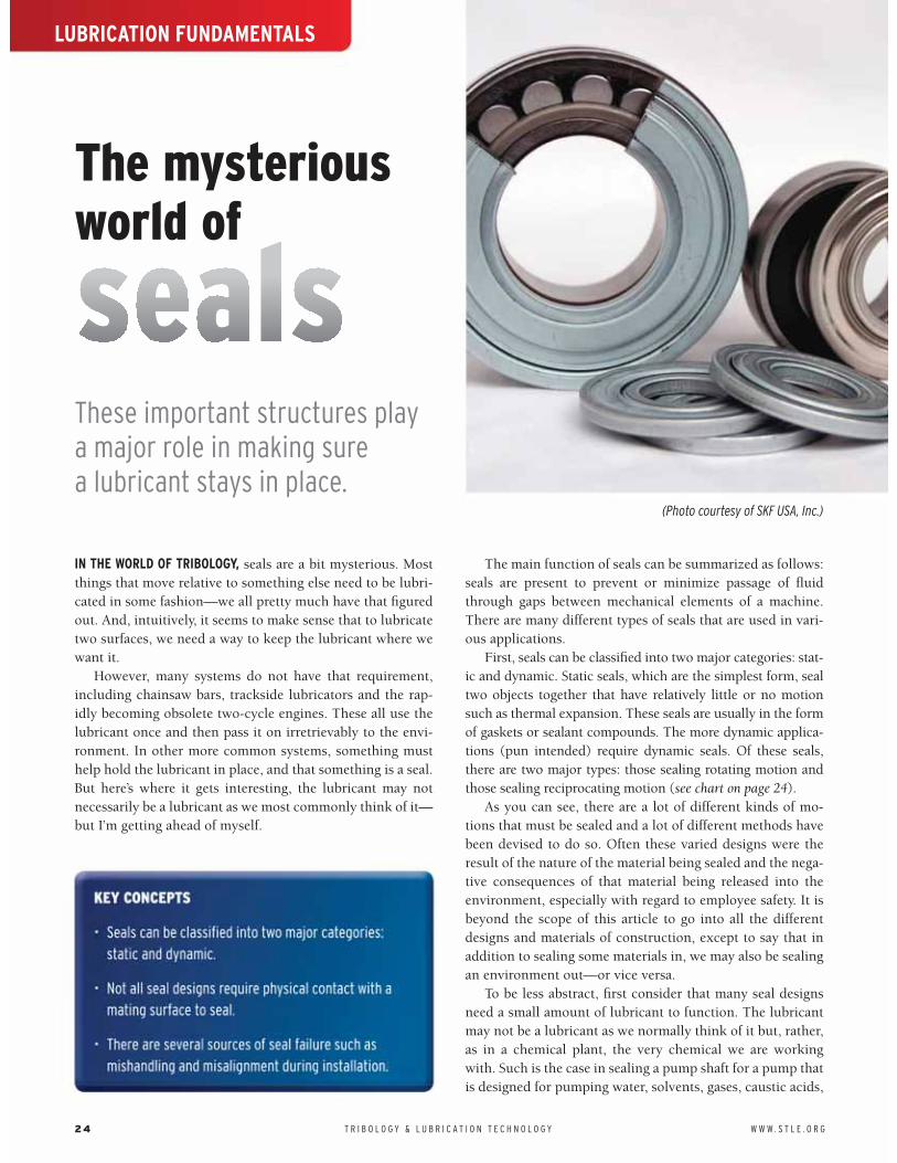
IN THE WORLD OF TRIBOLOGY, seals are a bit mysterious. Most things that move relative to something else need to be lubri-cated in some fashion—we all pretty much have that figured out. And, intuitively, it seems to make sense that to lubricate two surfaces, we need a way to keep the lubricant where we want it.
However, many systems do not have that requirement, including chainsaw bars, trackside lubricators and the rap-idly becoming obsolete two-cycle engines. These all use the lubricant once and then pass it on irretrievably to the envi-ronment. In other more common systems, something must help hold the lubricant in place, and that something is a seal. But here’s where it gets interesting, the lubricant may not necessarily be a lubricant as we most commonly think of it—but I’m getting ahead of myself.
The main function of seals can be summarized as follows: seals are present to prevent or minimize passage of fluid through gaps between mechanical elements of a machine. There are many different types of seals that are used in vari-ous applications.
First, seals can be classified into two major categories: stat-ic and dynamic. Static seals, which are the simplest form, seal two objects together that have relatively little or no motion such as thermal expansion. These seals are usually in the form of gaskets or sealant compounds. The more dynamic applica-tions (pun intended) require dynamic seals. Of these seals, there are two major types: those sealing rotating motion and those sealing reciprocating motion (see chart on page 24).
As you can see, there are a lot of different kinds of mo-tions that must be sealed and a lot of different methods have been devised to do so. Often these varied designs were the result of the nature of the material being sealed and the nega-tive consequences of that material being released into the environment, especially with regard to employee safety. It is beyond the scope of this article to go into all the different designs and materials of construction, except to say that in addition to sealing some materials in, we may also be sealing an environment out—or vice versa.
To be less abstract, first consider that many seal designs need a small amount of lubricant to function. The lubricant may not be a lubricant as we normally think of it but, rather, as in a chemical plant, the very chemical we are working with. Such is the case in sealing a pump shaft for a pump that is designed for pumping water, solvents, gases, caustic acids,
LUBRICATION FUNDAMENTALS
These important structures play a major role in making sure a lubricant stays in place.
The mysterious world of
24 T R I B O L O G Y & L U B R I C A T I O N T E C H N O L O G Y W W W . S T L E . O R G
(Photo courtesy of SKF USA, Inc.)

crude oil or whatever. This obviously makes the job more difficult, as some of these substances are not only potentially hazardous but also not very good lubricants and may be del-eterious to many types of sealing materials.
Thus, there are a number of considerations when it comes to the proper use of seals in machinery. In this article, we’ll review the major issues. Not all seal designs require physical contact with a mating surface to seal. A good example is lab-yrinth seals, which provide a tortuous path progressively building sufficient back pressure to prevent leakage.
However, with the more common seals that do have con-tact, the sliding surfaces of the seals are always lubricated by the fluid sealed or by supplementary lubrication fed directly into the space ahead of an exclusionary seal or from impreg-nated solid lubricants at the seal interface. Therefore, one has to consider wear of both the seal and its mating surface.
Ideally, the mating surface should be of a hard, wear-resis-tant material relative to the seal and the substance being sealed (which also can include slurries or other entrained particulate material). The hardness of the seal material and its compatibility with the fluid sealed are clearly critical fac-tors. Thus, ideally, when it is necessary to replace the seal, only the seal should be replaced and the mating surface only cleaned or lightly polished.
High surface-sliding speed and/or excessive pressure be-tween sliding surfaces increases temperature. At low speed with high pressure, lubrication may be difficult. These fac-tors can change seal/face geometry, which results in seal fail-ure. As alluded to above, abrasives in the fluid sealed or rough seal seats or mating surfaces can cause damage and leakage. Abrasion resistance of the seal material is an impor-tant factor. Interestingly, too much or too little surface roughness on sealed surfaces can equally be a problem.
SEAL FAILUREGiven the proper design considerations of speed, pressure, abrasion resistance, chemical resistance, surface roughness and materials of construction, there are other important fac-tors that can result in seal failure. Probably the most com-
mon is mishandling, which results in scratches, dings or chips in the seal face. This damage to the seal or its mating surface usually occurs during installation, storage or han-dling. Misalignment during installation is another major source of failure.
Even with proper design and installation, we are not out of the woods yet. We can have failure at startup where the seal faces are not lubricated. An example would be running the seal dry because a valve on the suction side of a pump was left closed.
Finally, like most mechanical systems, proper mainte-nance is important. Two key factors are “unscheduled move-ment,” which can be excessive axial or radial movement of a shaft against the seal; that is, excessive vibration or any other kind of related movement that is not part of the design. This could arise from a pump and motor that are firmly attached and aligned to a solid base. The other key factor is excessive contamination, which is often due to improper maintenance of filtration systems.
Like so many things we encounter in this tribologically influenced world of ours, there is often more to it than meets the eye, and seals are no exception. Without effective seals, our cars burn oil (bad rings), our environment is polluted due to leakage, employee safety can be jeopardized and the workplace becomes a pig sty with material leaking across the floor and a haze in the air.
In 1993 the Clean Air Act was introduced and since then the seal industry has implemented many very effective prac-tices when it comes to the proper installation and mainte-nance of seals. Even the most cursory look at our environ-ment versus 20 years ago clearly shows these advances.
Gaskets Sealants
Static
Mechanical
Axial
Lip Ring Split Ring Packings
Radial
Interfacial
Labrynth, Bushing,etc.
Interstitial (non-rubbing)
Rotating Shaft
Piston Rings Packings Diaphram
Reciprocating Shaft
Dynamic
Industrial Sealing
Seals are present to prevent or minimize passage of fluid through gaps between
mechanical elements of a machine.
W W W . S T L E . O R G T R I B O L O G Y & L U B R I C A T I O N T E C H N O L O G Y 25

I MAKE NO CLAIM TO BEING AN EXPERT IN TURBOMACHINERY, but these gadgets have always intrigued me as a class of machinery. At STLE’s Annual Meeting & Exhibition, most of the education courses and practical papers tend to gloss over lubrication of turbomachinery.
So here goes.In the world of turbines, there are three main types: hydro, steam
and gas. Well, I guess you should also include wind turbines, but they are quite a bit different than the above three. While I suppose you could call wind turbines a special case of a gas (air) turbine, to me they are a big wind-driven propeller hooked up to a gearbox that is, in turn, hooked up to a generator or alternator.
LUBRICATION FUNDAMENTALS
There are three main types of turbomachinery, and each has its own set of lubrication requirements.
TURBINES:What goes around comes around
26 T R I B O L O G Y & L U B R I C A T I O N T E C H N O L O G Y W W W . S T L E . O R G

HYDRO-TURBINESThese machines are driven by water and connected to an electricity generator or, more properly, a turbo-alternator to produce electricity. Hydro-turbines are on the low end in terms of application requirements but still significant. Thus, the lubricating oil sees temperatures in the oil sump on the order of 40 C-60 C with peak temperatures in the circula-tion system to maybe 70 C-95 C. Speeds are also moderate at around 50-600 rpm.
The oil also must lubricate guide vanes and control sys-tem components. The main lubrication issues for these kinds of turbines are water contamination and service life. Thus, mineral oil-based R&O oils that have good water demulsi-
bility are needed. The long service life is desirable to reduce maintenance costs and downtime. These are important due to the physical location of these turbines and the need for uninterrupted electrical power output.
STEAM TURBINESIndustrial steam turbines have multiple uses, usually to drive compressors, turbo-alternators, blowers, pumps and the like. In compressor applications, steam turbines and the compres-sor itself are similar in that they are both turbomachines. As such, they can behave similarly in terms of speed versus out-put. Thus, steam turbines are excellent for variable-speed turbo-compressors.
The main lubrication issues for hydro-turbines are water contamination and service life.
Figure 2 | Schematic of a steam turbine.
Figure 1 | Schematic of a hydro-turbine installation.
Figure 3 | Schematic of a hydro-turbine.
Figure 4 | A steam turbine installation.
W W W . S T L E . O R G T R I B O L O G Y & L U B R I C A T I O N T E C H N O L O G Y 27

Steam turbines can take on many different configura-tions, an analysis of which goes beyond the scope of this article. However, all multistage steam turbines require cool, clean oil supplied to their journal bearings.
This oil is supplied from several types of systems, but the key is that the oil must be delivered at the right flow rate, pressure and temperature. Often the driven equipment, such as the compressor, is also lubricated with the same oil, again at the right level of cleanliness, flow, pressure and tempera-ture. Furthermore, additional equipment also might be lu-bricated by this same system such as various control valves.
In general terms, steam turbines can operate up to speeds of 3,000 rpm, oil sumps around 40 C-70 C with peak or hot spot temperatures as high as 150 C. Clearly, aside from par-ticulate contamination, which is always a problem, steam turbines are subject to the effects of water and steam. Typi-cally turbine oils for steam turbines must be primarily re-sistant to rust and oxidation, the so-called R&O oils. Addi-tionally, turbine oils may contain antiwear and EP additives. Further, they should exhibit good demulsibility of water and be low foaming.
Interestingly, when one thinks about the highly formulat-ed automotive oils (10-20 percent additives), turbine oils by contrast are typically formulated with not much more than 1 percent additives. Therefore, the base oils are important. They can vary from Groups II, III, III+ or IV. The higher re-fined oils tend to have more inherent oxidation stability but, especially in the old days, they also tended to exhibit more varnish formation, likely because less refined oils tend to
solublize varnish rather than letting it form deposits.More modern formulations along with effective filtration
generally manage excessive varnish formation, or at least they should. Such oils typically have a viscosity index (VI) in the range of 95-100 so that the viscosity doesn’t vary too much from startup to peak temperatures.
GAS TURBINESIndustrial gas turbines, which are basically land-based jet en-gines (windmills notwithstanding), have some similarities to steam turbines except that steam is replaced with hot com-bustion gases. Thus, water contamination is not so much a problem with gas turbines. However, sump temperatures can range between 50 C-100 C with hot spot peaks up to 280 C. Speeds also are higher on the order of 3-7,000 rpm. Therefore, the performance requirements of the lubricating oil are necessarily higher, while lubricating oils based on hydro-treated basestocks are used for the less stringent ap-plications.
Clearly, gas turbines are a good application for synthetic lubricants such as polyalphaolefins and ester-based oils. Many of the larger, higher-performing industrial gas turbines (like the one shown in Figure 5) often use an aircraft engine core and require similar lubricants. For more advanced air-craft jet engines, which really are just higher-performing gas turbines, we have to kick it up a notch.
These turbines use primarily ester-based lubricants for their wide-temperature range capabilities such as those described by military specifications MIL-L-7808 and MIL-L-23699. For even higher-temperature resistance with oper-ating temperatures as high as 300 C, polyphenylether lubri-cants, as described in MIL-L-87100, could be used. But these are not for the financially faint of heart, and the polyphenyl-ethers have poor low-temperature performance, which is not so critical for an industrial gas turbine but can be a show-stopper for an airplane.
Clearly, turbomachinery, like the applications described above, affect our everyday lives in many ways. Keeping them going around allows us to go around.
In compressor applications, steam turbines and the compressor itself are similar in that
they are both turbomachines.
Figure 5 | General Electric LM2500 Gas Turbine
28 T R I B O L O G Y & L U B R I C A T I O N T E C H N O L O G Y W W W . S T L E . O R G

LUBRICATION FUNDAMENTALS
An overview of the machine elements that keep the industrial world turning.
What’s a gear?
W W W . S T L E . O R G T R I B O L O G Y & L U B R I C A T I O N T E C H N O L O G Y 29

HOW MANY OF YOU ARE OLD ENOUGH TO REMEMBER WALT DIS-NEY’S GYRO GEARLOOSE? Probably not many. I suppose he was
the first fictional tribologist. In fact, old Gyro was around before the word tribologist was coined. Gyro, who first appeared in Walt Disney Comic Book No. 140 in 1952, was a brilliant inven-tor of all kinds of humorous gadgets and devices, many of which included quite novel gear sets.
One can’t help but wonder how much he knew about the lubrication of his somewhat uniquely geared inventions. So let’s take a brief look at the world of gears.
First a definition: Gears are machine elements that trans-mit motion by means of successively engaging teeth. The gear teeth act as small levers. In general, gears are classified according to the relative position of the axis of their revo-lution. Thus, these axes are parallel, intersecting or, as you might guess, neither intersecting nor parallel—but non-in-tersecting.
Thus, gears connect shafts that operate from these differ-ent directions and, depending on the relative diameters and/or numbers of teeth per gear, can multiply speed or force in a manner analogous to a lever. So gears can reduce or increase speed, transmit power, increase or decrease torque, change direction and change axis of direction. Pretty handy traits for design engineers. Some of the more common gear types are:
SPUR GEARSSpur gears or straight-cut gears are the simplest type of gear. Spur gears connect parallel shafts and have involute (curling inward) teeth, parallel to the shafts (see diagram).
Spur gears consist of a cylinder or disk with the teeth projecting radially and, although not straight-sided in form, the edge of each tooth is straight and aligned parallel to the axis of rotation. These gears can be meshed together cor-rectly only if they are fitted to parallel shafts. Spur gears are relatively inexpensive to manufacture, cause no axial thrust between the gears and, while giving lower performance than other gear types, are generally satisfactory in low-speed, sim-ple applications. They can be noisy at higher speeds.
External Spur Gears
Internal Spur Gear
Involute Tooth
Gears are classified according to the relative position of the axis of their revolution.
30 T R I B O L O G Y & L U B R I C A T I O N T E C H N O L O G Y W W W . S T L E . O R G

HELICAL GEARSHelical gears offer a refinement over spur gears. Helical gears can be meshed in parallel or crossed orientations. He-lical gears also have involute teeth and are cut at an angle (called the helix angle) to the axis of rotation. Since the gear is curved, this angling causes the tooth shape to be a segment of a helix. The mating gears must have the same angle but in opposite hands (left and right). The angled teeth engage more gradually than do spur gear teeth, causing them to run more smoothly and quietly because there is continuous tooth contact. A disadvantage of helical gears is a resultant thrust along the axis of the gear, which needs to be accommodated by appropriate thrust bearings. The greater degree of sliding friction between the meshing teeth is often addressed with antiscuff and antiwear additives in the lubricant.
Helical gears are found in high-speed applications where good performance is needed. As you might expect, they can carry higher loads as there is a greater tooth cross section. Ob-viously, they are more expensive to manufacture. Another way to combat the axial thrust property is to use herringbone gears.
HERRINGBONE GEARSHerringbone gears consist of two helical gears of opposite hands that are mounted side-by-side on the shaft and thus cancel the resulting thrust forces.
BEVEL GEARS Bevel gears have a conical configuration as opposed to cy-lindrical for spur and helical. Thus, the two gears are, in effect, two truncated cones in rolling contact. Within this configuration there are straight bevels, which are like spur gears with no helix angle. Examples of bevel gears are mi-ter gears, equal in size with a 90-degree shaft angle, angu-lar gears with shaft angles other than 90 degrees, and crown gears where one gear is flat with a pitch angle of 90 degrees. Zerol bevel gears are an intermediate type between straight and spiral bevel gears. Their teeth are curved or crowned, so that contact takes place at the tooth center but not angled. Spiral bevel gears are analogous to helical gears but with a conical configuration. A hypoid gear is an example of a bevel gear that is neither parallel nor intersecting. Other examples of non-parallel and non-intersecting shaft gears are crossed helical gears and worm gears.
Crossed helical gears are used where the shafts are not parallel and not intersecting but rather skewed. They can be at 90 degrees or other angles. The teeth necessarily slide more and are, therefore, less efficient and often require high-ly additized lubricants.
Worm gears are used when large gear reductions are needed. It is common for worm gears to have reductions of 20:1 and even up to 300:1 or greater. Many worm gears have
Bevel Gears Zerol Gears Spiral Bevel Gears Hypoid Gears
INTERSECTING SHAFT GEARS
Parallel Helical Gears Crossed Helical Gears Herringbone Gears
W W W . S T L E . O R G T R I B O L O G Y & L U B R I C A T I O N T E C H N O L O G Y 3 1

Crossed Helical Gears
Worm Gears
Rack and pinion (The rack is like a gear
whose axis is infinity)
an interesting property that no other gear set has: the worm can easily turn the gear, but the gear cannot turn the worm. This is because the angle on the worm is so shallow that when the gear tries to spin it, the friction between the gear and the worm holds the worm in place. This feature is useful for machines such as conveyor systems in which the locking feature can act as a brake for the conveyor when the motor is not turning.
ROTARY TO TRANSLATION GEARS These gears transmit rotary motion from the pinion to trans-lational motion of the rack. The rack amounts to a gear of infinite radius with flat involute teeth.
The different designs of gears is an extremely complex subject and beyond the scope of this article. Figure 1 depicts a diagram of a gear that shows the key elements of gear de-sign.
Gears are made from a variety of materials dependent upon cost and the application. These materials include cast iron, powdered metals, steel, a variety of special nonferrous alloys and non-metallics such as the group of engineering plastics: nylon, acetal, UHMWPE, etc.
Gears are used in a wide variety of combinations in a wide variety of applications, such as in clocks, copiers, huge bull gears in drag lines, drawbridges, industrial gearboxes and re-lated industrial equipment and, of course, truck and automo-bile transmissions and differentials.
Figure 1 | Key Elements of Gear Design
32 T R I B O L O G Y & L U B R I C A T I O N T E C H N O L O G Y W W W . S T L E . O R G

Edited by STLE’s Alberta Section, the Basic Handbook of Lubrication (Third Edition) is a comprehensive text authored by more than 25 contributors. At 360 pages, this technical reference thoroughly covers some 30 topics with material edited to help newcomers and veterans to the lubricants industry. This reference is included in the recommended study material for STLE’s Certified Lubrication Specialist© and Oil Monitoring Analyst© (I&II) certifications.
Basic Handbook of LubricationThird Edition
• Oil viscosity & selecting correct grade depending on temperature
• Friction and lubrication regimes
• Mineral base oils
• Synthetic base oils and finished lubricants
• Used oil re-refining to create base oils
• Additives used in formulating lubricants
• New lubricants – analysis & testing
• Bearing lubrication
• Engine oils
• (Stationary) natural gas engine lubrication
• Enclosed gear oils: Classifications and additives
• Hydraulics fluids & related properties
• Hydraulic system components
• Hydraulic system components – sample calculation
• Hydraulic system components – sample calculation appendix
• Air compressor lubrication
• Reciprocating natural gas compressor lubrication
• Lubrication of electric motor bearings
• Turbine oils
• Refrigeration system lubrication
• Grease, an introduction
• Solid film lubricants
• Metalworking & preservative fluids
• Environmentally friendly lubricants
• Solvents & cleaners
• Aftermarket additives
• Centralized lubrication systems
• Pneumatics
• Filtration
• Introduction to seals
• Wear types
• Degradation and analysis of oils in service
• Condition monitoring & industrial machinery
• Effective bearing failure analysis
• A guide to purchasing lubricants
• Storage of new lubricants (health, safety and environmental considerations)
• Used oil collection
• Glossary of lubrication terms
Price: $125 to STLE members. $159 to others.
Comes in spiral-bound and perfect-bound editions.Available only through STLE! Order at www.stle.org, or call 847-825-5536.
Society of Tribologists and Lubrication Engineers840 Busse Highway, Park Ridge, Illinois 60068P: 847-825-5536 F: 847-825-1456 www.stle.org [email protected]
CHAPTER TITLES
The only reference you need to understand tribology fundamentals!

STLE University is your personalized, centralized location for continuing education in the field of tribology and lubrication engineering. We provide you with the latest educational information in the field while at the same time providing opportunities to enhance your career and create value for your company.
STLE University was designed with our members in mind. STLE provides education that is:
• Focused: STLE offers a variety of courses and webinars that are designed for specific audiences working in the field of tribology and lubrication engineering. Our offerings vary by topical area, level of expertise (basic to advanced) and audience segment (formulators, salespeople, distributors, students, etc.).
• Flexible: Courses are available in-person and online to fit around any busy schedule, and are designed to meet your varying educational needs. If you need a short course, an introduction/overview or a long, in-depth course, chances are STLE University has something to fit your needs. There are varying types and formats of courses to match up with your available time commitment.
• Accessible: STLE offers a variety of educational opportunities, both in-person and online. Our in-person education locations change yearly, ensuring you have a chance to visit one nearby. Our online options allow you to purchase a course at any time and start it immediately. As long as you have a computer and an Internet con-nection, you have online education. Also, STLE University is not limited to members. However, you receive significant discounts if you become a member.
All of our educational opportunities also apply towards STLE’s recertifica-tion requirements. Visit www.stle.org/university for more information and schedule of upcoming courses and webinars.
Society of Tribologists and Lubrication Engineers840 Busse Highway • Park Ridge, Illinois (USA) 60068 • Phone: (847) 825-5536 • Fax: (847) 825-1456 • Web site: www.stle.org/university
Education Your Way. Focused. Flexible. Accessible.
Choose from a variety of educational formats:
Online Offerings
• Online certificate courses
- Fundamentals of Lubrication
• Online short courses
- Basic Lubrication
- Lubrication Composition
- Fluid Management & Recycling
- Metalworking Fluids
• Monthly Webinars
Topics include bearings, gears, hydraulics, MWFs and much more!
In-Person Offerings
• Annual Meeting courses
• Local Section courses
• Certificate courses
• On-site education courses
Find out more about STLE! Sign up and follow us on: