
Lubrication - Bosch Rexroth...Bosch Rexroth AG Roller Rail Systems R310EN 2302 (2006.04) Lubrication...
15
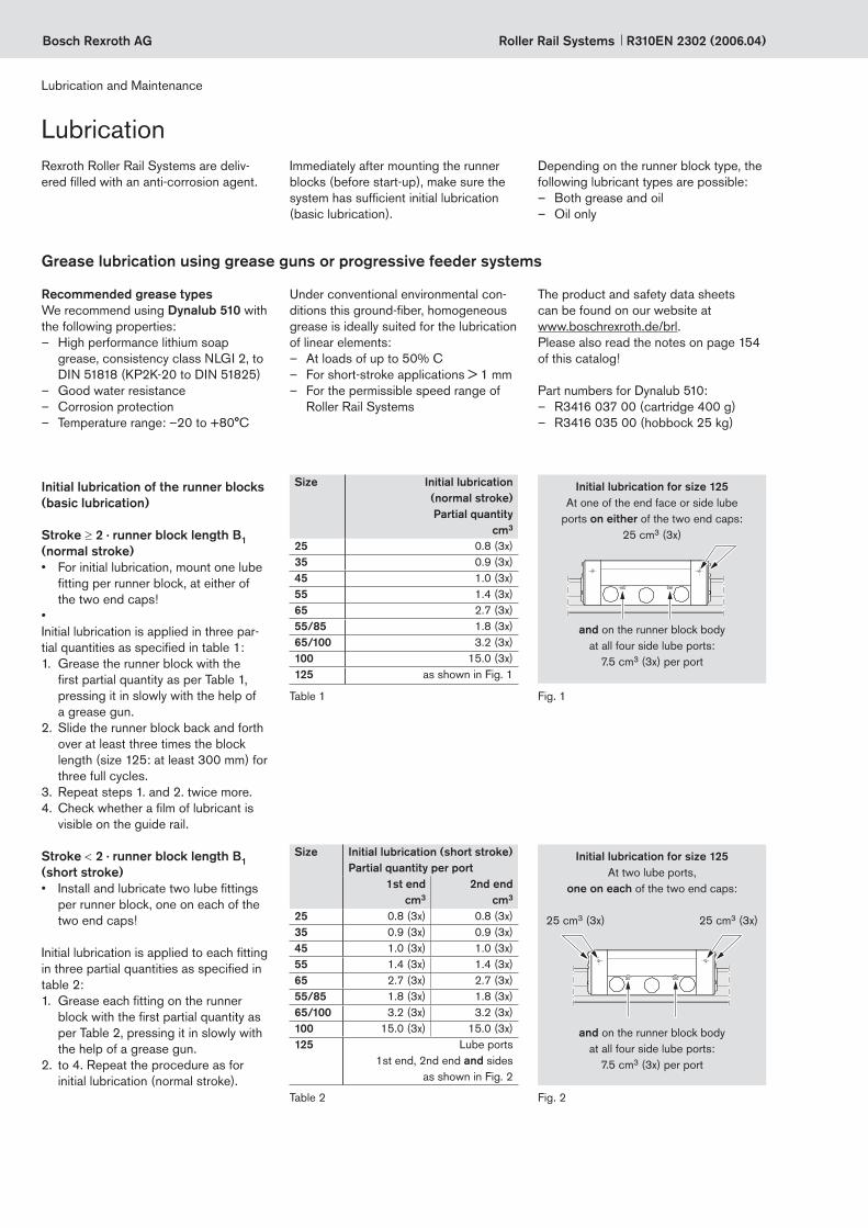
Bosch Rexroth AG Roller Rail Systems R310EN 2302 (2006.04) Lubrication Rexroth Roller Rail Systems are deliv- ered filled with an anti-corrosion agent. Immediately after mounting the runner blocks (before start-up), make sure the system has sufficient initial lubrication (basic lubrication). Recommended grease types We recommend using Dynalub 510 with the following properties: – High performance lithium soap grease, consistency class NLGI 2, to DIN 51818 (KP2K-20 to DIN 51825) – Good water resistance – Corrosion protection – Temperature range: –20 to +80°C and on the runner block body at all four side lube ports: 7.5 cm 3 (3x) per port Initial lubrication for size 125 At one of the end face or side lube ports on either of the two end caps: 25 cm 3 (3x) Grease lubrication using grease guns or progressive feeder systems Lubrication and Maintenance Size Initial lubrication (short stroke) Partial quantity per port 1st end cm 3 2nd end cm 3 25 0.8 (3x) 0.8 (3x) 35 0.9 (3x) 0.9 (3x) 45 1.0 (3x) 1.0 (3x) 55 1.4 (3x) 1.4 (3x) 65 2.7 (3x) 2.7 (3x) 55/85 1.8 (3x) 1.8 (3x) 65/100 3.2 (3x) 3.2 (3x) 100 15.0 (3x) 15.0 (3x) 125 Lube ports 1st end, 2nd end and sides as shown in Fig. 2 Table 2 Stroke < 2 · runner block length B 1 (short stroke) • Install and lubricate two lube fittings per runner block, one on each of the two end caps! Initial lubrication is applied to each fitting in three partial quantities as specified in table 2: 1. Grease each fitting on the runner block with the first partial quantity as per Table 2, pressing it in slowly with the help of a grease gun. 2. to 4. Repeat the procedure as for initial lubrication (normal stroke). Under conventional environmental con- ditions this ground-fiber, homogeneous grease is ideally suited for the lubrication of linear elements: – At loads of up to 50% C – For short-stroke applications > 1 mm – For the permissible speed range of Roller Rail Systems The product and safety data sheets can be found on our website at www.boschrexroth.de/brl. Please also read the notes on page 154 of this catalog! Part numbers for Dynalub 510: – R3416 037 00 (cartridge 400 g) – R3416 035 00 (hobbock 25 kg) Initial lubrication of the runner blocks (basic lubrication) Stroke ≥ 2 · runner block length B 1 (normal stroke) • For initial lubrication, mount one lube fitting per runner block, at either of the two end caps! • Initial lubrication is applied in three par- tial quantities as specified in table 1: 1. Grease the runner block with the first partial quantity as per Table 1, pressing it in slowly with the help of a grease gun. 2. Slide the runner block back and forth over at least three times the block length (size 125: at least 300 mm) for three full cycles. 3. Repeat steps 1. and 2. twice more. 4. Check whether a film of lubricant is visible on the guide rail. Size Initial lubrication (normal stroke) Partial quantity cm 3 25 0.8 (3x) 35 0.9 (3x) 45 1.0 (3x) 55 1.4 (3x) 65 2.7 (3x) 55/85 1.8 (3x) 65/100 3.2 (3x) 100 15.0 (3x) 125 as shown in Fig. 1 Table 1 Fig. 1 and on the runner block body at all four side lube ports: 7.5 cm 3 (3x) per port Initial lubrication for size 125 At two lube ports, one on each of the two end caps: Fig. 2 25 cm 3 (3x) Depending on the runner block type, the following lubricant types are possible: – Both grease and oil – Oil only 25 cm 3 (3x)
Transcript of Lubrication - Bosch Rexroth...Bosch Rexroth AG Roller Rail Systems R310EN 2302 (2006.04) Lubrication...
Bosch Rexroth AG Roller Rail Systems R310EN 2302 (2006.04)
LubricationRexroth Roller Rail Systems are deliv-ered filled with an anti-corrosion agent.
Immediately after mounting the runner blocks (before start-up), make sure the system has sufficient initial lubrication (basic lubrication).
Recommended grease typesWe recommend using Dynalub 510 with the following properties:
– High performance lithium soap grease, consistency class NLGI 2, to DIN 51818 (KP2K-20 to DIN 51825)
– Good water resistance – Corrosion protection – Temperature range: –20 to +80°C
and on the runner block body at all four side lube ports:
7.5 cm3 (3x) per port
Initial lubrication for size 125At one of the end face or side lube
ports on either of the two end caps: 25 cm3 (3x)
Grease lubrication using grease guns or progressive feeder systems
Lubrication and Maintenance
Size Initial lubrication (short stroke)Partial quantity per port
1st endcm3
2nd endcm3
25 0.8 (3x) 0.8 (3x)35 0.9 (3x) 0.9 (3x)45 1.0 (3x) 1.0 (3x)55 1.4 (3x) 1.4 (3x)65 2.7 (3x) 2.7 (3x)55/85 1.8 (3x) 1.8 (3x)65/100 3.2 (3x) 3.2 (3x)100 15.0 (3x) 15.0 (3x)125 Lube ports
1st end, 2nd end and sidesas shown in Fig. 2
Table 2
Stroke < 2 · runner block length B1 (short stroke)• Install and lubricate two lube fittings
per runner block, one on each of the two end caps!
Initial lubrication is applied to each fitting in three partial quantities as specified in table 2:1. Grease each fitting on the runner
block with the first partial quantity as per Table 2, pressing it in slowly with the help of a grease gun.
2. to 4. Repeat the procedure as for initial lubrication (normal stroke).
Under conventional environmental con-ditions this ground-fiber, homogeneous grease is ideally suited for the lubrication of linear elements:
– At loads of up to 50% C – For short-stroke applications > 1 mm – For the permissible speed range of
Roller Rail Systems
The product and safety data sheets can be found on our website at www.boschrexroth.de/brl. Please also read the notes on page 154 of this catalog!
Part numbers for Dynalub 510: – R3416 037 00 (cartridge 400 g) – R3416 035 00 (hobbock 25 kg)
Initial lubrication of the runner blocks (basic lubrication)
Stroke ≥ 2 · runner block length B1 (normal stroke)• For initial lubrication, mount one lube
fitting per runner block, at either of the two end caps!
• Initial lubrication is applied in three par-tial quantities as specified in table 1:1. Grease the runner block with the
first partial quantity as per Table 1, pressing it in slowly with the help of a grease gun.
2. Slide the runner block back and forth over at least three times the block length (size 125: at least 300 mm) for three full cycles.
3. Repeat steps 1. and 2. twice more.4. Check whether a film of lubricant is
visible on the guide rail.
Size Initial lubrication (normal stroke) Partial quantity
cm3
25 0.8 (3x)35 0.9 (3x)45 1.0 (3x)55 1.4 (3x)65 2.7 (3x)55/85 1.8 (3x)65/100 3.2 (3x)100 15.0 (3x)125 as shown in Fig. 1
Table 1 Fig. 1
and on the runner block body at all four side lube ports:
7.5 cm3 (3x) per port
Initial lubrication for size 125At two lube ports,
one on each of the two end caps:
Fig. 2
25 cm3 (3x)
Depending on the runner block type, the following lubricant types are possible:
– Both grease and oil – Oil only
25 cm3 (3x)

Bosch Rexroth AGRoller Rail SystemsR310EN 2302 (2006.04)
or on the runner block body at all four side lube ports:
15 cm3 per port
Relubrication for size 125At one of the end face or side lube
ports on either of the two end caps: 55 cm3
Size Relubrication (short stroke)per port
1st endcm3
2nd endcm3
25 0.8 0.835 0.9 0.945 1.0 1.055 1.4 1.465 2.7 2.755/85 1.8 1.865/100 3.2 3.2100 15.0 15.0125 Side ports
as shown in Fig. 4
Table 4
Stroke < 2 · runner block length B1 (short stroke)• When the travel distance shown as
the relubrication interval in Fig. 5 has been reached, apply the relubrication quantity as specified in Table 4.
• At each lubrication cycle the runner block should be traversed through a lubricating stroke of 3 · runner block length B1. In any case, the lubricating stroke must be at least the length of the runner block. If the largest possi-ble lubricating stroke is smaller than the runner block length B1, lubricant must be applied to the guide rail. Please consult us for details.
Please also read the notes on relubrica-tion on page 154 of this catalog!
Relubrication of runner blocks
Stroke ≥ 2 · runner block length B1 (normal stroke)• When the travel distance shown as
the relubrication interval in Fig. 5 has been reached, apply the relubrication quantity as specified in Table 3.
Please also read the notes on relubrica-tion on page 154 of this catalog!
Size Relubrication (normal stroke)
cm3
25 0.8 35 0.9 45 1.0 55 1.4 65 2.7 55/85 1.8 65/100 3.2 100 15.0 125 as shown in
Fig. 3
Table 3 Fig. 3
On the runner block body at all four side lube ports:
15 cm3 per port
Relubrication for size 125
Fig. 4
LubricationGrease lubrication using grease guns or progressive feeder systems (continued)
Lubrication and Maintenance

Bosch Rexroth AG
0 0,1 0,2 0,3 0,4F/C
10
30
100
150
250
500800
1000
1
s (k
m)
65 + 65/100
100 + 125
55 + 55/85
35
25
45
Roller Rail Systems R310EN 2302 (2006.04)
Lubrication
Lubrication and Maintenance
NotesThe load ratio F/C is the quotient of the equivalent dynamic load on the bearing F (making allowance for a preload of 8% C or 13% C) divided by the dynamic load capacity C (see “General Technical Data and Calculations”).
c If other lubricants are used, this may lead to a reduction in the relubri-cation intervals, the achievable travel in short-stroke applications, and the load capacities. Possible chemi-cal interactions between the plastic materials, lubricants and preservative oils must also be taken into account.
c Do not use greases containing solid particles (e.g., graphite or MoS2)!
c When using progressive feeder systems, do not go below the mini-mum dosing quantity for relubrication as given in Table 9.
c If the system is to be exposed to metalworking fluids, always apply 2 to 5 lubricant pulses at the begin-ning or when the system has been at a standstill for a longer period. If possible, apply lubricant while the system is in motion. Carry out clean-ing and lubricating strokes (see “Maintenance”).
c If the application conditions involve dirt, vibrations, impacts, etc. we recommend shortening the relu-brication intervals accordingly. Even under normal operating condi-tions, the system must be relubri- cated at the latest after 2 years due to aging of the grease.
If your application involves more de-manding environmental requirements (such as clean room, vacuum, food in-dustry environment, increased exposure to fluids or aggressive media, extreme temperatures), please consult us. These situations must be investigated on a case by case basis and may require the use of a special lubricant. Be sure to have all the information concerning your application at hand when contacting us.
c Switching from grease to oil lubrication while the system is in service is not possible as the lubri-cation ducts are already filled with grease, and oil will not be able to pass through them.
Load-dependent relubrication in-tervals for grease lubrication using grease guns or progressive feeder systems (“dry axes”)
Sizes 25 to 125
The following conditions apply: – Grease lubricant Dynalub 510 – or alternatively
Castrol Longtime PD 2 – Maximum speed:
vmax = 2 m/s – No exposure to metalworking fluids – Standard seals – Ambient temperature:
T = 20 – 30°C
Fig. 5
Key to graphs = relubrication interval
expressed as travel (km)C = dynamic load capacity (N)F = equivalent dynamic load (N)
Grease lubrication using grease guns or progressive feeder systems (continued)
For relubrication intervals in applications involving exposure to metal-working fluids, please consult us.

Bosch Rexroth AGRoller Rail SystemsR310EN 2302 (2006.04)
Liquid grease lubrication We recommend using Dynalub 520 with the following properties:
– High performance lithium soap grease, consistency class NLGI 00, to DIN 51818 (GP00K-20 to DIN 51826)
– Good water resistance – Corrosion protection – Temperature range: –20 to +80°C
and on the runner block body at all four side lube ports:
7.5 cm3 (3x) per port
Liquid grease lubrication via single-line piston distributor systems
Size Initial lubrication (short stroke)Partial quantity per port
1st endcm3
2nd endcm3
25 0.8 (3x) 0.8 (3x)35 0.9 (3x) 0.9 (3x)45 1.0 (3x) 1.0 (3x)55 1.4 (3x) 1.4 (3x)65 2.7 (3x) 2.7 (3x)55/85 1.8 (3x) 1.8 (3x)65/100 3.2 (3x) 3.2 (3x)100 15.0 (3x) 15.0 (3x)125 Lube ports
1st end, 2nd end and sides as shown in Fig. 7
Table 6
Stroke < 2 · runner block length B1 (short stroke)• Install and lubricate two lube fittings
per runner block, one on each of the two end caps!
Initial lubrication is applied to each fitting in three partial quantities as specified in table 6:1. Grease each fitting on the runner
block with the first partial quantity as per Table 6, pressing it in slowly with the help of a grease gun.
2. to 4. Repeat the procedure as for initial lubrication (normal stroke).
Under conventional environmental con-ditions this ground-fiber, homogeneous grease is ideally suited for the lubrication of linear elements:
– In single-line centralized lubrication systems
– At loads of up to 50% C – For short-stroke applications > 1 mm – For the permissible speed range of
Roller Rail Systems – For miniature versions
The product and safety data sheets can be found on our website at www.boschrexroth.de/brl. Please also read the notes on page 158 of this catalog!
Part numbers for Dynalub 520: – R3416 043 00 (cartridge 400 g) – R3416 042 00 (bucket 5 kg)
Stroke ≥ 2 · runner block length B1 (normal stroke)• For initial lubrication, mount one lube
fitting per runner block, at either of the two end caps!
Initial lubrication is applied in three par-tial quantities as specified in table 5:1. Grease the runner block with the
first partial quantity as per Table 5, pressing it in slowly with the help of a grease gun.
2. Slide the runner block back and forth over at least three times the block length (size 125: at least 300 mm) for three full cycles.
3. Repeat steps 1. and 2. twice more.4. Check whether a film of lubricant is
visible on the guide rail.
Table 5 Fig. 6
and on the runner block body at all four side lube ports:
7.5 cm3 (3x) per port
Fig. 7
Initial lubrication of the runner blocks (basic lubrication)
We recommend applying initial lubrica-tion with a manual grease gun before connecting the equipment to the central-ized lubrication system.
If initial lubrication is nevertheless carried out via the centralized lubrication system, it is essential that all lines and piston distributors should be filled. The pulse count can then be calculated from the partial quantities and the piston distribu-tor size according to Table 9.
Lubrication
Lubrication and Maintenance
Initial lubrication for size 125At one of the end face or side lube
ports on either of the two end caps: 25 cm3 (3x)
Initial lubrication for size 25At two lube ports,
one on each of the two end caps:
25 cm3 (3x) 25 cm3 (3x)
Size Initial lubrication (normal stroke)Partial quantity
cm3
25 0.8 (3x)35 0.9 (3x)45 1.0 (3x)55 1.4 (3x)65 2.7 (3x)55/85 1.8 (3x)65/100 3.2 (3x)100 15.0 (3x)125 as shown in Fig. 6

Bosch Rexroth AG Roller Rail Systems R310EN 2302 (2006.04)
Lubrication
Lubrication and Maintenance
or on the runner block body at all four side lube ports:
15 cm3 per port
Size Relubrication (short stroke)per port
1st endcm3
2nd endcm3
25 0.8 0.835 0.9 0.945 1.0 1.055 1.4 1.465 2.7 2.755/85 1.8 1.865/100 3.2 3.2100 15.0 15.0125 Side ports
as shown in Fig. 9
Table 8
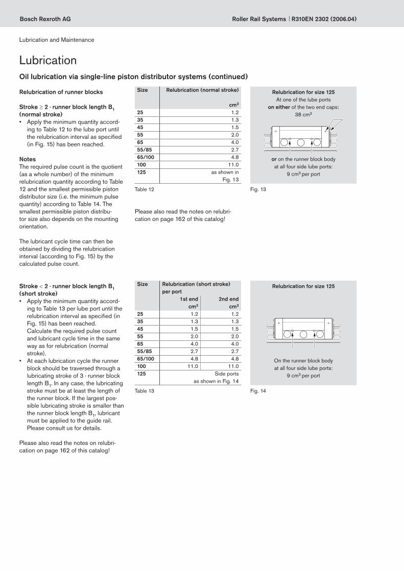
Stroke < 2 · runner block length B1 (short stroke)• Apply the minimum quantity accord-
ing to Table 8 per lube port until the relubrication interval as specified (in Fig. 10) has been reached. Calculate the required pulse count and lubricant cycle time in the same way as for relubrication (normal stroke).
• At each lubrication cycle the runner block should be traversed through a lubricating stroke of 3 · runner block length B1. In any case, the lubricating stroke must be at least the length of the runner block. If the largest pos-sible lubricating stroke is smaller than the runner block length B1, lubricant must be applied to the guide rail. Please consult us for details.
Please also read the notes on relubrica-tion on page 158 of this catalog!
Relubrication of runner blocks
Stroke ≥ 2 · runner block length B1 (normal stroke)• Apply the minimum quantity accord-
ing to Table 7 to the lube port until the relubrication interval as specified (in Fig. 10) has been reached.
NotesThe required pulse count is the quotient (as a whole number) of the minimum relubrication quantity according to Table 7 and the smallest permissible piston dis-tributor size (i.e. the minimum pulse quantity) according to Table 9. The smallest permissible piston distribu-tor size also depends on the mounting orientation.
The lubricant cycle time can then be obtained by dividing the relubrication interval (according to Fig. 10) by the calculated pulse count (see design example on page 163).
Size Relubrication (normal stroke)
cm3
25 0.8 35 0.9 45 1.0 55 1.4 65 2.7 55/85 1.8 65/100 3.2 100 15.0 125 as shown in
Fig. 8
Table 7 Fig. 8
On the runner block body at all four side lube ports:
15 cm3 per port
Relubrication for size 125
Fig. 9
Liquid grease lubrication via single-line piston distributor systems (continued)
Relubrication for size 125At one of the end face or side lube
ports on either of the two end caps: 55 cm3
Please also read the notes on relubrica-tion on page 158 of this catalog!

Bosch Rexroth AGRoller Rail SystemsR310EN 2302 (2006.04)
Runner blocks Smallest permissible piston distributor size (⇔ minimum pulse quantity) per lube port (cm3) for liquid grease, NLGI class 00Size
Part numbers Mounting orientations 25 35 45 55 65 55/85 65/100 100 125R18.. ... 10 or ... 60 orR18.. ... 13 or ... 63 orR18.. ... 16 or ... 66
Horizontal I, IV 0.06 0.1 0.1 0.1 0.2 0.1 0.2 0.3 0.3Vertical II, V 0.06 0.1 0.1 0.1 0.2 0.1 0.2 0.3 0.3Wall mounting III, VI 0.06 0.1 0.1 0.1 0.2 0.1 0.2 0.3 (2x)2) 0.3 (2x)2)3)
R18.. ... 18 or ... 68 Wall mounting III, VI2) – 0.06 0.06 0.06 – – – – –R1859 620 31 Wall mounting III – – – – 0.1 – – – –
Smallest permissible piston distributor sizes for liquid grease lubrication through single-line centralized systems1)
Horizontal1 lube fitting at either of the two end caps
Mounting orientation I – normal stroke Mounting orientation II – normal stroke Mounting orientation III – normal stroke
Mounting orientation IV – short stroke Mounting orientation V – short stroke Mounting orientation VI – short stroke
Horizontal, top-downSame port
Horizontal2 lube ports, one on each of the two end caps
Horizontal, top-down Same port
Vertical to slanting horizontal2 lube ports, one on each of the two end caps (top and bottom)
Vertical to slanting horizontal1 lube port at top end cap
Vertical to slanting, top-downSame port
Wall mounting2 lube ports, one on each of the two end caps
Wall mounting1 lube fitting at either of the two end caps
For runner block R1859 620 31,2 lube ports, one on each end cap, either
at the end face or on the mounting face
Not possible with runner block
R1859 620 31Vertical to slanting, top-down
Same port
Table 91) Applies under the following conditions:
- Dynalub 520 (or alternatively Castrol Longtime PD 00) and piston distributors from Vogel - Lube ducts must be filled - Ambient temperature T = 20 – 30 °C
2) Sizes 100 and 125: Either two pulses in short succession or two metering valves each delivering one pulse simultaneously3) Size 125: 0.3 cm3 per port when all four ports in the runner block body are used
0° to max. ±90°
0° to max. ±90°
0° to max. ±90°
0° to max. ±90°
Liquid grease lubrication via single-line piston distributor systems (continued)
Lubrication
Lubrication and Maintenance

Bosch Rexroth AG
0 0,1 0,2 0,3 0,4F/C
1
10
75
22,5
112,5187,5
100
375600
1000
s (k
m)
65 + 65/100
100 + 125
55 + 55/85
3525
45
Roller Rail Systems R310EN 2302 (2006.04)
Lubrication
Lubrication and Maintenance
Load-dependent relubrication inter-vals for liquid grease lubrication via single-line piston distributor systems (“dry axes”)
Sizes 25 to 125
The following conditions apply: – Liquid grease Dynalub 520
or alternatively Castrol Longtime PD 00
– Maximum speed: vmax = 2 m/s
– No exposure to metalworking fluids – Standard seals – Ambient temperature:
T = 20 – 30°C
Fig. 10
Key to graphs = relubrication interval
expressed as travel (km)C = dynamic load capacity (N)F = equivalent dynamic load (N)
NotesThe load ratio F/C is the quotient of the equivalent dynamic load on the bearing F (making allowance for a preload of 8% C or 13% C) divided by the dynamic load capacity C (see “General Technical Data and Calculations”).
c If other lubricants are used, this may lead to a reduction in the relubri-cation intervals, the achievable travel in short-stroke applications, and the load capacities. Possible chemi-cal interactions between the plastic materials, lubricants and preservative oils must also be taken into account. In addition, the suitability of the lubri-cant for use in single-line centralized lubrication systems must be ensured.
c Do not use greases containing solid particles (e.g., graphite or MoS2)!
c If the system is to be exposed to metalworking fluids, always apply 2 to 5 lubricant pulses at the begin-ning or when the system has been at a standstill for a longer period. If possible, apply lubricant while the system is in motion. Carry out clean-ing and lubricating cycles (see “Maintenance”).
c If the application conditions involve dirt, vibrations, impacts, etc. we recommend shortening the relu-brication intervals accordingly. Even under normal operating conditions, the system must be relubricated at the latest after 2 years due to aging of the grease.
If your application involves more de-manding environmental requirements (such as clean room, vacuum, food in-dustry environment, increased exposure to fluids or aggressive media, extreme temperatures), please consult us. These situations must be investigated on a case by case basis and may require the use of a special lubricant. Be sure to have all the information concerning your application at hand when contacting us.
c Switching from grease to oil lubrication while the system is in service is not possible as the lubri-cation ducts are already filled with grease, and oil will not be able to pass through them.
We recommend using piston distributors from Vogel. These should be installed as close as possible to the lube ports of the runner bocks.Long lines and small line diameters should be avoided, and the lines should be laid on an upward slant.
A selection of possible lube fittings is given in the section “General Acces- sories – Runner Blocks” (for more in-formation, you should also consult the manufacturer of your lubrication system).
If other consumers are connected to the single-line centralized lubrication system, the weakest link in the chain will deter-mine the lubrication cycle time.
Liquid grease lubrication via single-line piston distributor systems (continued)
For relubrication intervals in applications involving exposure to metalworking fluids, please consult us.Without taking distance traveled into accountAssume 3 to 4 pulses per hour as a guide value for relubrication.

Bosch Rexroth AGRoller Rail SystemsR310EN 2302 (2006.04)
Oil lubricantWe recommend using Shell Tonna S 220 with the following properties:
– Special demulsifying oil CLP or CGLP to DIN 51517-3 for machine bed tracks and tool guides
– A blend of highly refined mineral oils and additives
– Can be used even when mixed with significant quantities of metalworking fluids
and on the runner block body at all four side lube ports:
9 cm3 (1x) per port
Oil lubrication via single-line piston distributor systems
Size Initial lubrication (short stroke)Partial quantity per port
1st endcm3
2nd endcm3
25 1.2 (2x) 1.2 (2x)35 1.3 (2x) 1.3 (2x)45 1.5 (2x) 1.5 (2x)55 2.0 (2x) 2.0 (2x)65 4.0 (2x) 4.0 (2x)55/85 2.7 (2x) 2.7 (2x)65/100 4.8 (2x) 4.8 (2x)100 11.0 (2x) 11.0 (2x)125 Lube ports
1st end, 2nd end and sides as shown in Fig. 12
Table 11
Stroke < 2 · runner block length B1 (short stroke)• Install and lubricate two lube fittings
per runner block, one on each of the two end caps!
Initial lubrication is applied in two partial quantities per lube fitting as specified in table 11:1. Apply the first of the oil quantities as
specified in table 11 to each of the lube fittings on the runner block.
2. to 4. Repeat the procedure as for initial lubrication (normal stroke).
Please also read the notes on page 162 of this catalog!
Stroke ≥ 2 · runner block length B1 (normal stroke)• For initial lubrication, mount one lube
fitting per runner block, at either of the two end caps!
Initial lubrication is applied in two partial quantities as specified in table 10:1. Apply the first of the oil quantities as
specified in table 10 to the runner block.
2. Slide the runner block back and forth over at least three times the block length (size 125: at least 300 mm) for three full cycles.
3. Repeat steps 1. and 2.4. Check whether a film of lubricant is
visible on the guide rail.
Size Initial lubrication (normal stroke)Partial quantity
cm3
25 1.2 (2x)35 1.3 (2x)45 1.5 (2x)55 2.0 (2x)65 4.0 (2x)55/85 2.7 (2x)65/100 4.8 (2x)100 11.0 (2x)125 as shown in Fig. 11
Table 10 Fig. 11
and on the runner block body at all four side lube ports:
9 cm3 (1x) per port
Fig. 12
Initial lubrication of the runner blocks (basic lubrication)
We recommend applying initial lubrica-tion with a manual grease gun before connecting the equipment to the central-ized lubrication system.
If initial lubrication is nevertheless carried out via the centralized lubrication system, it is essential that all lines and piston distributors should be filled. The pulse count can then be calculated from the partial quantities and the piston distribu-tor size according to Table 14.
Initial lubrication for size 125At one of the end face or side lube
ports on either of the two end caps: 38 cm3 (1x)
Lubrication
Lubrication and Maintenance
Initial lubrication for size 125At two lube ports,
one on each of the two end caps:
38 cm3 (1x) 38 cm3 (1x)
Bosch Rexroth AG Roller Rail Systems R310EN 2302 (2006.04)
Lubrication
Lubrication and Maintenance
or on the runner block body at all four side lube ports:
9 cm3 per port
Relubrication for size 125At one of the lube ports
on either of the two end caps: 38 cm3
Size Relubrication (short stroke)per port
1st endcm3
2nd endcm3
25 1.2 1.235 1.3 1.345 1.5 1.555 2.0 2.065 4.0 4.055/85 2.7 2.765/100 4.8 4.8100 11.0 11.0125 Side ports
as shown in Fig. 14
Table 13
Stroke < 2 · runner block length B1 (short stroke)• Apply the minimum quantity accord-
ing to Table 13 per lube port until the relubrication interval as specified (in Fig. 15) has been reached. Calculate the required pulse count and lubricant cycle time in the same way as for relubrication (normal stroke).
• At each lubrication cycle the runner block should be traversed through a lubricating stroke of 3 · runner block length B1. In any case, the lubricating stroke must be at least the length of the runner block. If the largest pos-sible lubricating stroke is smaller than the runner block length B1, lubricant must be applied to the guide rail. Please consult us for details.
Please also read the notes on relubri-cation on page 162 of this catalog!
Relubrication of runner blocks
Stroke ≥ 2 · runner block length B1 (normal stroke)• Apply the minimum quantity accord-
ing to Table 12 to the lube port until the relubrication interval as specified (in Fig. 15) has been reached.
NotesThe required pulse count is the quotient (as a whole number) of the minimum relubrication quantity according to Table 12 and the smallest permissible piston distributor size (i.e. the minimum pulse quantity) according to Table 14. The smallest permissible piston distribu-tor size also depends on the mounting orientation.
The lubricant cycle time can then be obtained by dividing the relubrication interval (according to Fig. 15) by the calculated pulse count.
Size Relubrication (normal stroke)
cm3
25 1.235 1.345 1.555 2.065 4.055/85 2.765/100 4.8100 11.0125 as shown in
Fig. 13
Table 12 Fig. 13
On the runner block body at all four side lube ports:
9 cm3 per port
Relubrication for size 125
Fig. 14
Oil lubrication via single-line piston distributor systems (continued)
Please also read the notes on relubri-cation on page 162 of this catalog!

Bosch Rexroth AGRoller Rail SystemsR310EN 2302 (2006.04)
Runner blocks Smallest permissible piston distributor size (⇔ minimum pulse quantity) per lube port (cm3) at oil viscosity 220 mm2/sSize
Part numbers Mounting orientations 25 35 45 55 65 55/85 65/100 100 125R18.. ... 10 or ... 60 orR18.. ... 13 or ... 63 orR18.. ... 16 or ... 66
Horizontal I, IV 0.06 0.10 0.10 0.16 0.2 0.6 0.6 1.5 1.5Vertical II, V 0.06 0.10 0.10 0.16 0.2 0.6 0.6 1.5 1.5Wall mounting III, VI2) 0.10 0.20 0.40 0.40 0.6 1.0 1.5 1.5 (3x)3) 1.5 (3x)3)4)
R18.. ... 17 or ... 67 Horizontal I, IV – 0.06 0.06 0.10 – – – – –Vertical II, V – 0.06 0.06 0.10 – – – – –Wall mounting III, VI2) – 0.06 0.10 0.16 – – – – –
R18.. ... 18 or ... 68 Wall mounting III, VI2) – 0.06 0.06 0.10 – – – – –R1859 620 31 Wall mounting III – – – – 0.1 – – – –
Smallest permissible piston distributor sizes for oil lubrication via single-line centralized systems1)
Horizontal1 lube fitting at either of the two end caps
Mounting orientation I – normal stroke Mounting orientation II – normal stroke Mounting orientation III – normal stroke
Mounting orientation IV – short stroke Mounting orientation V – short stroke Mounting orientation VI – short stroke
Horizontal, top-down Same port
Horizontal2 lube ports, one on each of the two end caps
Top-downSame port
Vertical to slanting horizontal2 lube ports, one on each of the two end caps (top and bottom)
Vertical to slanting horizontal1 lube port at top end cap
Vertical to slanting, top-downSame port
Wall mountingR18.. ... 18/68: 2 ports, both on one of the two end caps
0° to max. ±90°
Vertical to slanting, top-downSame port
Table 141) Applies under the following conditions: Lube oil Shell Tonna S 220 using piston distributors from Vogel 2) Please note the varying suitability of the runner bocks for the mounting orientations wall mounting III, VI:
+++ runner blocks R18.. ... 18 or ... 68 ++ runner blocks R18.. ... 17 or ... 67 + runner blocks R18.. ... 10/13/16 or ... 60/63/66
3) Sizes 100 and 125: Either three pulses in short succession or three metering valves delivering one pulse simultaneously4) Size 125: 1.5 cm3 per port when all four ports in the runner block body are used
0° to max. ±90°
0° to max. ±90°
Oil lubrication via single-line piston distributor systems (continued)
Lubrication
Lubrication and Maintenance
Runner blocks
R18.. ... 1.: 1 lube port on either of the two end caps;
R1859 620 31: 2 ports, one on each end cap, either at the end face or on
the mounting face
Wall mountingR18.. ... 18/68: 4 ports, 2 on each of the two end caps
0° to max. ±90°
Runner blocks
R18.. ... 1.: 2 lube ports, one on each
of the two end capsNot possible
with runner block R1859 620 31

Bosch Rexroth AG
0 0,1 0,2 0,3 0,4F/C
10
15
5075
100125
250400
1000
1
s (k
m)
65 + 65/100
100 + 125
55 + 55/85
3525
45
Roller Rail Systems R310EN 2302 (2006.04)
Lubrication
Lubrication and Maintenance
Load-dependent relubrication inter-vals for oil lubrication via single-line piston distributor systems (“dry axes”)
Sizes 25 to 125
The following conditions apply: – Shell Tonna S 220 – Maximum speed:
vmax = 2 m/s – No exposure to metalworking fluids – Standard seals – Ambient temperature:
T = 20 – 30°C
Fig. 15
NotesThe load ratio F/C is the quotient of the equivalent dynamic load on the bearing F (making allowance for a preload of 8% C or 13% C) divided by the dynamic load capacity C (see “General Technical Data and Calculations”).
c If other lubricants are used, this may lead to a reduction in the relubri-cation intervals, the achievable travel in short-stroke applications, and the load capacities. Possible chemi-cal interactions between the plastic materials, lubricants and preservative oils must also be taken into account. In addition, the suitability of the lubri-cant for use in single-line centralized lubrication systems must be ensured.
c Do not use greases containing solid particles (e.g., graphite or MoS2)!
c If the system is to be exposed to metalworking fluids, always apply 2 to 5 lubricant pulses at the begin-ning or when the system has been at a standstill for a longer period. If possible, apply lubricant while the system is in motion. Carry out clean-ing and lubricating cycles (see “Maintenance”).
c If the application conditions involve dirt, vibrations, impacts, etc. we recommend shortening the relu-brication intervals accordingly.
If your application involves more de-manding environmental requirements (such as clean room, vacuum, food in-dustry environment, increased exposure to fluids or aggressive media, extreme temperatures), please consult us. These situations must be investigated on a case by case basis and may require the use of a special lubricant. Be sure to have all the information concerning your application at hand when contacting us.
c Switching from grease to oil lubrication while the system is in service is not possible as the lubri-cation ducts are already filled with grease, and oil will not be able to pass through them.
We recommend using piston distributors from Vogel. These should be installed as close as possible to the lube ports of the runner bocks. Long lines and small line diameters should be avoided, and the lines should be laid on an upward slant.
A selection of possible lube fittings is given in the section “General Acces- sories – Runner Blocks” (for more in-formation, you should also consult the manufacturer of your lubrication system).
If other consumers are connected to the single-line centralized lubrication system, the weakest link in the chain will deter-mine the lubrication cycle time.
Oil lubrication via single-line piston distributor systems (continued)
Key to graphs = relubrication interval
expressed as travel (km)C = dynamic load capacity (N)F = equivalent dynamic load (N)
For relubrication intervals in applications involving exposure to metalworking fluids, please consult us.Without taking distance traveled into accountAssume 3 to 4 pulses per hour as a guide value for relubrication.
Bosch Rexroth AGRoller Rail SystemsR310EN 2302 (2006.04)
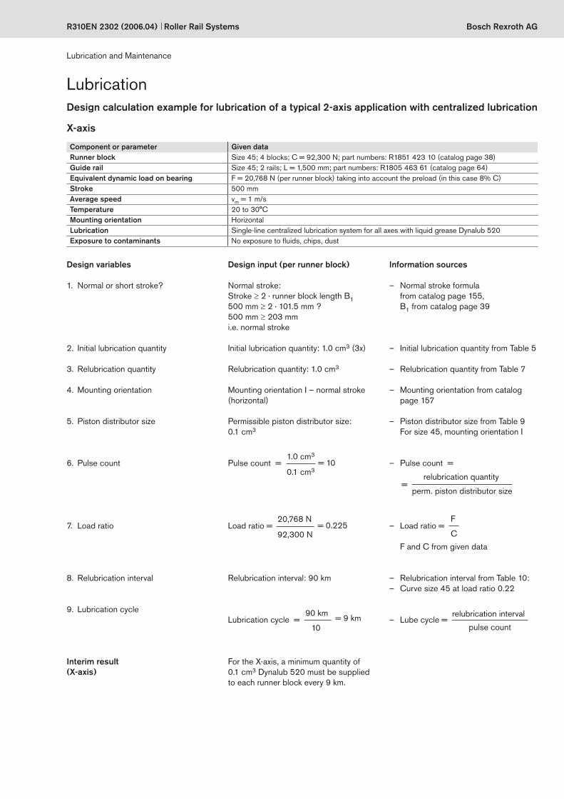
– Normal stroke formula from catalog page 155, B1 from catalog page 39
– Initial lubrication quantity from Table 5
– Relubrication quantity from Table 7
– Mounting orientation from catalog page 157
– Piston distributor size from Table 9 For size 45, mounting orientation I
– Pulse count =
– Load ratio = F and C from given data
– Relubrication interval from Table 10: – Curve size 45 at load ratio 0.22
– Lube cycle =
X-axis
Design calculation example for lubrication of a typical 2-axis application with centralized lubrication
Normal stroke: Stroke ≥ 2 · runner block length B1 500 mm ≥ 2 · 101.5 mm ? 500 mm ≥ 203 mm i.e. normal stroke
Initial lubrication quantity: 1.0 cm3 (3x)
Relubrication quantity: 1.0 cm3
Mounting orientation I – normal stroke (horizontal)
Permissible piston distributor size: 0.1 cm3 Pulse count =
Load ratio =
Relubrication interval: 90 km
Lubrication cycle =
For the X-axis, a minimum quantity of 0.1 cm3 Dynalub 520 must be supplied to each runner block every 9 km.
1. Normal or short stroke?
2. Initial lubrication quantity
3. Relubrication quantity
4. Mounting orientation
5. Piston distributor size
6. Pulse count
7. Load ratio
8. Relubrication interval
9. Lubrication cycle
Interim result(X-axis)
Design input (per runner block)
1.0 cm3
0.1 cm3= 10
20,768 N
92,300 N= 0.225
relubrication interval
pulse count
90 km
10= 9 km
Component or parameter Given dataRunner block Size 45; 4 blocks; C = 92,300 N; part numbers: R1851 423 10 (catalog page 38)Guide rail Size 45; 2 rails; L = 1,500 mm; part numbers: R1805 463 61 (catalog page 64)Equivalent dynamic load on bearing F = 20,768 N (per runner block) taking into account the preload (in this case 8% C)Stroke 500 mmAverage speed vm = 1 m/sTemperature 20 to 30°CMounting orientation HorizontalLubrication Single-line centralized lubrication system for all axes with liquid grease Dynalub 520Exposure to contaminants No exposure to fluids, chips, dust
Lubrication
Lubrication and Maintenance
Design variables Information sources
relubrication quantity =
perm. piston distributor size
F
C

Bosch Rexroth AG Roller Rail Systems R310EN 2302 (2006.04)
Normal stroke: Stroke ≥ 2 · runner block length B1 50 mm ≥ 2 · 79.6 mm ? 50 mm < 159.6 mm i.e. short stroke
2 lube ports, initial lubrication quantity per lube port: 0.9 cm3 (3x)
2 lube ports, relubrication quantity per port: 0.9 cm3
Mounting orientation V – short stroke (vertical)
Permissible piston distributor size: 0.1 cm3
Pulse count =
Load ratio =
Relubrication interval: 375 km
Lubrication cycle =
For the Y-axis, a minimum quantity of 0.1 cm3 Dynalub 520 must be supplied to each runner block every 42 km.
Lubrication
Lubrication and Maintenance
Y-axis
Component or parameter Given dataRunner block Size 35; 4 blocks; C = 56,300 N; part numbers: R1851 323 10 (catalog page 38)Guide rail Size 35; 2 rails; L = 1,000 mm; part numbers: R1805 333 61Equivalent dynamic load on bearing F = 8,445 N (per runner block) taking into account the preload (in this case 8% C)Stroke 50 mmAverage speed vm = 1 m/sTemperature 20 to 30°CMounting orientation VerticalLubrication Single-line centralized lubrication system for all axes with liquid grease Dynalub 520Exposure to contaminants No exposure to fluids, chips, dust
End result(two-axis lubrication)
– Normal stroke formula from catalog page 155, B1 from catalog page 39
– Initial lubrication quantity from Table 5
– Relubrication quantity from Table 7
– Mounting orientation from catalog page 157
– Piston distributor size from Table 9 for size 35, mounting orientation V
– Formula as for X-axis
– Formula as for X-axis, F and C from given data
– Relubrication interval from Fig. 10: – Curve size 35 at load ratio 0.15
– Formula as for X-axis
1. Normal or short stroke?
2. Initial lubrication quantity
3. Relubrication quantity
4. Mounting orientation
5. Piston distributor size
6. Pulse count
7. Load ratio
8. Relubrication interval
9. Lubrication cycle
Interim result(Y-axis)
Design input (per runner block)
0.9 cm3
0.1 cm3= 9
8,445 N
56,300 N= 0.15
375 km9
= 42 km
Design variables Information sources
Since both the axes in this example are supplied by a single-line centralized lubrication system, the X-axis with its smaller lube cycle (9 km) determines the overall cycle of the system, i.e. the Y-axis will also be lubricated every 9 km. The number of ports and the mini-mum lubricant quantities determined for each axis remain the same.
Bosch Rexroth AG
Tmax
Ø 1,5
2,5
12
3
12
3
5
24
5
4
Roller Rail SystemsR310EN 2302 (2006.04)
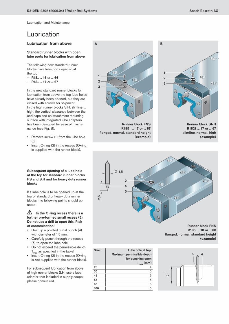
Lubrication from above
Standard runner blocks with open lube ports for lubrication from above
The following new standard runner blocks have lube ports opened at the top:
– R18.. ... 16 or ... 66 – R18.. ... 17 or ... 67
In the new standard runner blocks for lubrication from above the top lube holes have already been opened, but they are closed with screws for shipment.In the high runner blocks S.H, slimline ... high, the vertical clearance between the end caps and an attachment mounting surface with integrated lube adapters has been designed for ease of mainte-nance (see Fig. B).
• Remove screw (1) from the lube hole (3).
• Insert O-ring (2) in the recess (O-ring is supplied with the runner block).
Lubrication
Lubrication and Maintenance
A B
Runner block FNSR1851 ... 17 or ... 67
flanged, normal, standard height(example)
Runner block SNHR1821 ... 17 or ... 67
slimline, normal, high(example)
Subsequent opening of a lube hole at the top for standard runner blocks F.S and S.H and for heavy duty runner blocks
If a lube hole is to be opened up at the top of standard or heavy duty runner blocks, the following points should be noted:
c In the O-ring recess there is a further pre-formed small recess (5). Do not use a drill to open this. Risk of contamination! • Heat up a pointed metal punch (4)
with diameter of 1.5 mm. • Carefully punch through the recess
(5) to open the lube hole.• Do not exceed the permissible depth
Tmax as specified in the table!• Insert O-ring (2) in the recess (O-ring
is not supplied with the runner block).
For subsequent lubrication from above of high runner blocks S.H, use a lube adapter (not included in supply scope; please consult us).
Size Lube hole at top: Maximum permissible depth
for punching open Tmax (mm)
25 435 545 555 565 5100 5
Runner block FNSR185. ... 10 or ... 60
flanged, normal, standard height(example)

Bosch Rexroth AG Roller Rail Systems R310EN 2302 (2006.04)
MaintenanceCleaning cycle Dirt can settle and encrust on guide
rails, especially when these are not enclosed.To ensure that seals and cover strips retain their functionality, this dirt must be removed at regular intervals.
It is advisable to run the machine through at least one full cleaning cycle over the entire installed rail length every 8 hours. Depending on the amount of soiling and on the coolant used, more frequent cleaning may be required.
Before shutting down the machine, always run two cleaning cycles over the entire installed rail length, followed by at least two lubrication cycles over the entire installed rail length.
Checking accessories All accessories used for scraping or wiping the guide rails must be checked at regular intervals.In environments with heavy soiling, it is advisable to replace all the parts in the soiled area.We recommend checking the accesso-ries at least once a year.
Lubrication and Maintenance