LSWR 30' Saloon of 1896-8 - Raymond Walley 30' Saloon of 1896-8 Manufactured by: Southwark Bridge...
11
© Raymond Walley 2014 – All Rights Reserved LSWR 30' Saloon of 1896-8 Manufactured by: Southwark Bridge Models, 7 Came Close, Chandler's Ford, EASTLEIGH, SO53 1HH Tel: 023 8026 2414 - 07890 471158. [email protected] http://www.sbmodels.org/ An interesting 6 wheel Saloon This is being built for a friend who models the LNWR and will serve as part of a special train representing those that went North for the Grouse shooting season in the 1900s
-
Upload
phungthien -
Category
Documents
-
view
215 -
download
2
Transcript of LSWR 30' Saloon of 1896-8 - Raymond Walley 30' Saloon of 1896-8 Manufactured by: Southwark Bridge...

© Raymond Walley 2014 – All Rights Reserved
LSWR 30' Saloon of 1896-8 Manufactured by: Southwark Bridge Models, 7 Came Close, Chandler's Ford, EASTLEIGH, SO53 1HH
Tel: 023 8026 2414 - 07890 471158. [email protected] http://www.sbmodels.org/
An interesting 6 wheel Saloon
This is being built for a friend who models the LNWR and will serve as part of
a special train representing those that went North for the Grouse shooting
season in the 1900s
© Raymond Walley 2014 – All Rights Reserved
The kit arrives as a large sheet of etch securely taped to a stout wooden board, a
bag of bits for buffer, bolts, screws, etc., and 13 pages of quite detailed
instructions. Not supplied are wire, or tube required for various tanks and
cylinders
There is a drawing of the completed
vehicle but to a very small scale and
appears to have been reproduced from
GR Weddell's book LSWR Carriages,
Vol 1. Pictures are an essential aid
and, fortunately, Ian Hopkins models
the LSWR and lent me the required
book
I began with the springs and hangers.
The springs are Ivan's normal etched
laminates while the hangers are made
up from etches and wire. They look
very delicate but are surprisingly
robust once all the parts of a spring
unit has been soldered up. I used my usual method of drilling appropriate holes
in the RSU base plate to act as a jig and each unit was easy to produce.
However, the distance for the jig pins in the instructions, stated as 28mm (for
the 4mm version perhaps?) for the distance between the J hangers, is wrong and
should be 49.5mm
The parts for the brakes need the holes drilling out in the shoes and support so
that they can be soldered up accurately using a wire jig. The instructions make

© Raymond Walley 2014 – All Rights Reserved
reference to this and suggest one needs patience for the job. I considered it
essential if the brake blocks were to really look the part
These parts fit into slots in the outer trucks of the Cleminson suspension unit.
Ivan's version of a Cleminson suspension system is designed to enable the
wheels to be removed, hence the bolts visible on each unit. The centre unit
slides horizontally inside projecting 'ears' that are soldered into the floor.
Unfortunately, one pair fouls the bolt heads so I made up a couple of
replacement 'L' shaped supports and soldered those in place, removing the
offending parts.
Here the brakes are as complete as I intend to make them; as usual I have left
off any parts that are not visible from normal viewing angles or distances but
the prominent brake activating levers need to be present. However, there are
eight parts 14 required to make up these levers, two per lever, but there are only
five on the fret so three more had to be fabricated. The yokes are only soldered
in to one side of the brake rigging. The fitting to the bolted side of the unit is
free to move when the unit is disassembled to remove the wheel sets.
The ends with all
the bits fitted
ready for
assembly to the
body. I had to
remove the short
handrails on the
right hand one
when modifying
both parts to
make fixing to the sides easier, see later. Also, there is no provision for the gas
control handle, see later.
© Raymond Walley 2014 – All Rights Reserved
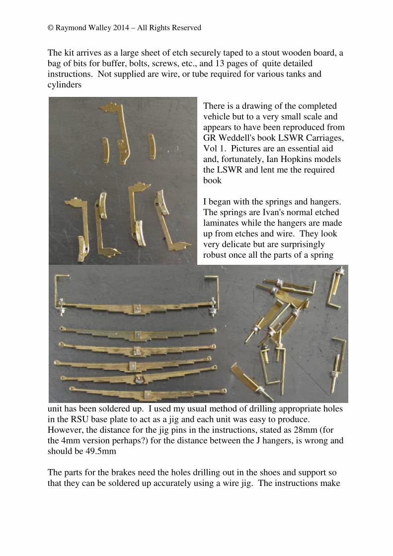
The fixed windows in the sides have separate bolection mouldings and the RSU
came in to its own for these delicate parts. Here are both sides shewing all the
parts fitted prior to assembly of the body. The window drop lights come with
the hinges ready etched on to the frame so fitting them ensures both accuracy
and the correct depth for the hinges; the lower door hinges are separate etched
parts. There is also provision made for an open window with an integral frame.
I later modified the compartment door on one side with it; there are suitable
etched parts for the hinges to be added.
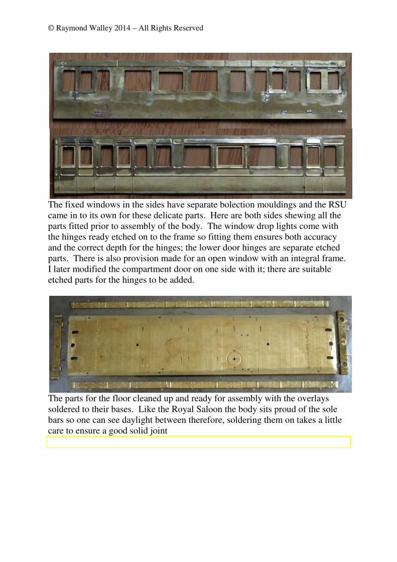
The parts for the floor cleaned up and ready for assembly with the overlays
soldered to their bases. Like the Royal Saloon the body sits proud of the sole
bars so one can see daylight between therefore, soldering them on takes a little
care to ensure a good solid joint

© Raymond Walley 2014 – All Rights Reserved
Here is the underside
with the gas tanks,
vacuum reservoir and
vacuum cylinder all
mounted. The sizes
quoted for the various
tubes to make these
parts in the
instructions are not
correct (possibly they
are 4mm sizes?). The
gas tanks require
7/16" tube, the vacuum reservoir 3/8" and the vacuum cylinder 1/2". On the
prototype the vacuum cylinder sits at an angle; easy enough to cut the tube so
that it sits in its mounting slot at an angle thus:
The ends fit between the sides but, the
thickness of the ends at that point is
some 0.2mm and the etched framing
protrudes beyond. Edge soldering that
I considered could be difficult so
decided to add some 1mm square
stock to the ends and a sliver of scrap
to the straight part of the sides so that
I could offer up an end at the correct
distance for a good fit. It did make
things easier. One has to make
allowance for the strengthening piece
at the top of the side, not difficult. It
was at this point that I had to remove
the handrails from the non-step end
and replace them once the body was
assembled
A simple matter then to solder one

© Raymond Walley 2014 – All Rights Reserved
end to one side but be sure to fix the correct end to the correct side; they are
handed as the body will only fit one way. That's right; I got it wrong first time!
Here are the two joined sides and ends awaiting final assembly. The open
window in the left compartment is visible.
And here are the two side/end units assembled to form the body with the
compartment partitions added. This makes up into a robust unit and all that
now needs to be added are the three roof fixing cross members. A piece of
scrap brass was used to blank off the lavatory from the corridor
Now required is a roof. The recommended method for the roof is to use layers
of plasticard sanded to shape. An extremely messy method very prone to
excessive electrostatic dust all over the workshop, as mentioned by Ian Hopkins
when he built one for the Royal Saloon. I have decided to try using timber
instead, lime wood with a shellacked card finish and fix it with self tappers
through the roof support ribs.
Here is the basic roof section shewing evidence of a previous attempt to glue the
© Raymond Walley 2014 – All Rights Reserved
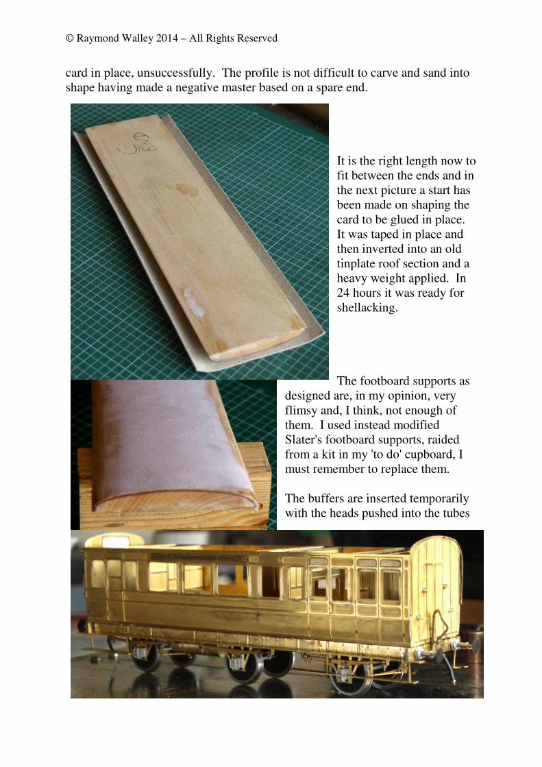
card in place, unsuccessfully. The profile is not difficult to carve and sand into
shape having made a negative master based on a spare end.
It is the right length now to
fit between the ends and in
the next picture a start has
been made on shaping the
card to be glued in place.
It was taped in place and
then inverted into an old
tinplate roof section and a
heavy weight applied. In
24 hours it was ready for
shellacking.
The footboard supports as
designed are, in my opinion, very
flimsy and, I think, not enough of
them. I used instead modified
Slater's footboard supports, raided
from a kit in my 'to do' cupboard, I
must remember to replace them.
The buffers are inserted temporarily
with the heads pushed into the tubes
© Raymond Walley 2014 – All Rights Reserved
that serve as shanks; once it is painted they can be fixed permanently.
However, the owner has decided that he wants integral buffers fitted instead so
these are scheduled to be removed
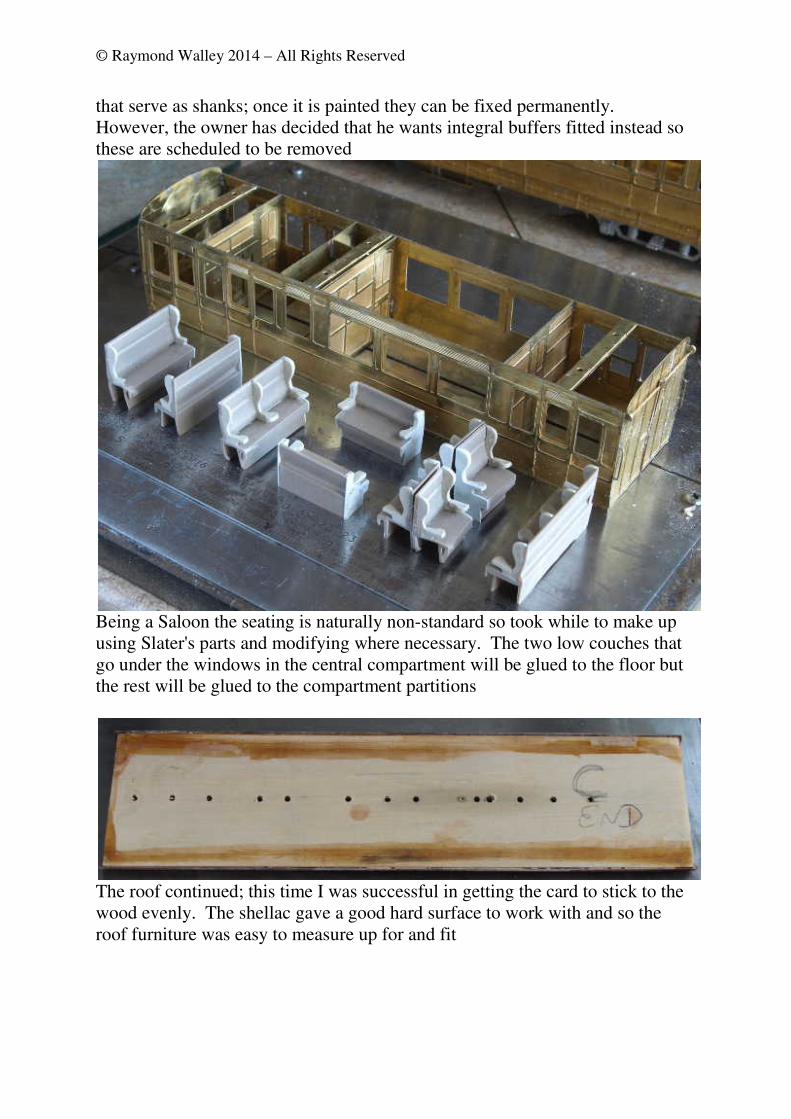
Being a Saloon the seating is naturally non-standard so took while to make up
using Slater's parts and modifying where necessary. The two low couches that
go under the windows in the central compartment will be glued to the floor but
the rest will be glued to the compartment partitions
The roof continued; this time I was successful in getting the card to stick to the
wood evenly. The shellac gave a good hard surface to work with and so the
roof furniture was easy to measure up for and fit
© Raymond Walley 2014 – All Rights Reserved
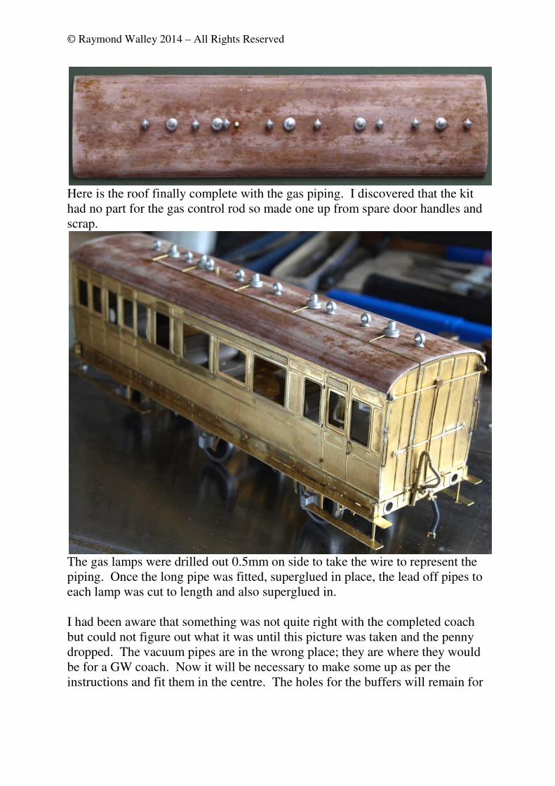
Here is the roof finally complete with the gas piping. I discovered that the kit
had no part for the gas control rod so made one up from spare door handles and
scrap.
The gas lamps were drilled out 0.5mm on side to take the wire to represent the
piping. Once the long pipe was fitted, superglued in place, the lead off pipes to
each lamp was cut to length and also superglued in.
I had been aware that something was not quite right with the completed coach
but could not figure out what it was until this picture was taken and the penny
dropped. The vacuum pipes are in the wrong place; they are where they would
be for a GW coach. Now it will be necessary to make some up as per the
instructions and fit them in the centre. The holes for the buffers will remain for
© Raymond Walley 2014 – All Rights Reserved
my friend to fit his own preferred pattern and couplings too. I have corrected
the vacuum pipes as can be seen in the picture at the top the page
Late modifications. The centre
wheels set as designed is free to move
vertically so far that it easily become
badly misaligned and prevents the
vehicle being put on track without
some fiddling. I modified it by
simply soldering a wire keep in place
thus:
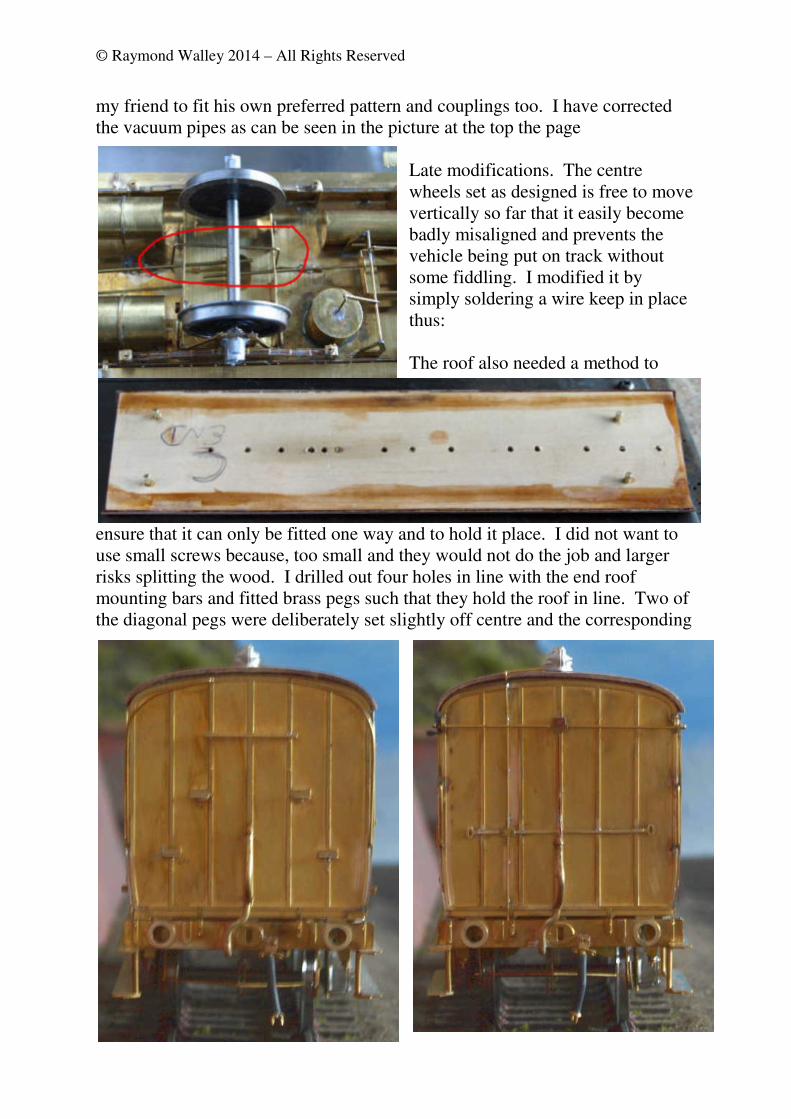
The roof also needed a method to
ensure that it can only be fitted one way and to hold it place. I did not want to
use small screws because, too small and they would not do the job and larger
risks splitting the wood. I drilled out four holes in line with the end roof
mounting bars and fitted brass pegs such that they hold the roof in line. Two of
the diagonal pegs were deliberately set slightly off centre and the corresponding
© Raymond Walley 2014 – All Rights Reserved
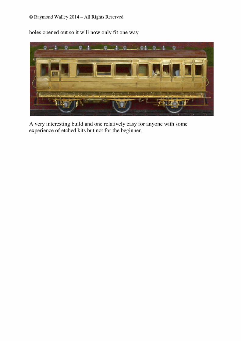
holes opened out so it will now only fit one way
A very interesting build and one relatively easy for anyone with some
experience of etched kits but not for the beginner.