LSB6 RGB RSX - English -...
15
A N N U N C I A T O R M O D U L E S A N D S Y S T E M S 1111 Sofia 35 Edison Str., Tel. 0897 954300, E-mail: office@ sigmatron.bg ISO9001:2008 ®LSB6 RGB RSX ANNUNCIATOR MODULE MANUAL
-
Upload
duongthien -
Category
Documents
-
view
215 -
download
0
Transcript of LSB6 RGB RSX - English -...
AN
NU
NC
IA
TO
R M
OD
UL
ES
AN
D S
YS
TE
MS
1111 Sofia 35 Edison Str., Tel. 0897 954300, E-mail: office@ sigmatron.bg ISO9001:2008
®LSB6 RGB RSX
ANNUNCIATOR MODULE
MANUAL

USE
Annunciator modules LSB6 RGB RSX is last generation device
for registration of events, intended to keep attention of the
engineering staff. In case of out of range of the technological
process annunciator module activate blinking lightings at 6
windows and external audible device. LSB6 has in build Event
Recorder with Serial port RS485. LSB6 has Serial port
RS232/485/422. The Communication protocol Modbus RTU
makes it compatible with SCADA systems. The Configuration
settings of the LSB6 are accessible by software configuration
tool.
FUNCTIONAL MODES
Annunciator modules LSB6 RGB RSX three basic functional modes.
1. In case of Input ON – blinking window with First basic color, Audible Output ON
After acknowledgement continuously lighting window with First basic color, Audible Output OFF.
In case of Input OFF – Lighting window with First basic color OFF.
2. In case of Input ON - blinking window with First basic color, Audible Output ON
After acknowledgement continuously lighting window with Second basic color ON, Audible Output
OFF In case of Input OFF – Lighting window with Second basic color OFF.
3. In case of Input ON - blinking window with First basic color, Audible Output ON
After acknowledgement continuously lighting window with Second basic color ON, Audible Output
OFF In case of Input OFF – Lighting window with Third basic color ON.
The Basic Colors can be adjusted by Customer. Default colors are:
• First basic color – White
• Second basic color – Green
• Third basic color – Yellow
FUNCTIONAL MODES OF THE AUDIBLE RELAY
1. In case of Input ON continuously up to acknowledge.
2. In case of Input ON continuously up to acknowledge + short ON/OFF after Input
3. Аuto Quit – In case of Input ON automatically OFF after run out the set time.
4. Auto Quit + short ON/OFF after Input OFF.
Auto Quit Mode Time 1 – 60 seconds
Short ON/OFF after Input OFF 1 – 5 seconds
INPUTS AND POLARITY
Annunciator modules LSB6 RGB RSX can be operate with two types Input signals – potential and no potential
(Dry contact). The Customer has to define one of those options by order. For option Potential Input voltage
range is 10 – 250 V AC/DC and has to be define too in the Customer order. The polarity of the Input signals
can be set by software tool.
ANNUNCIATOR INPUTS
The inputs of the Annunciator modules LSB6 RGB RS are galvanic insulated and protected by varistors. The
Inputs have Software filtering Algorithm for rejection disturbances. The input hardware components are
designed for long term active working under industrial condition and protected by additional treatment with
polyester film. The Input settings can be set by Software tool. Accessible settings for all Inputs are:
• Input type - AC/ DC
• Input Polarity – per every Input.
• Input Software filtering Algorithm Time -Input ON 10 – 1000 mS
• Input Software filtering Algorithm Time -Input OFF 10 – 1000 mS
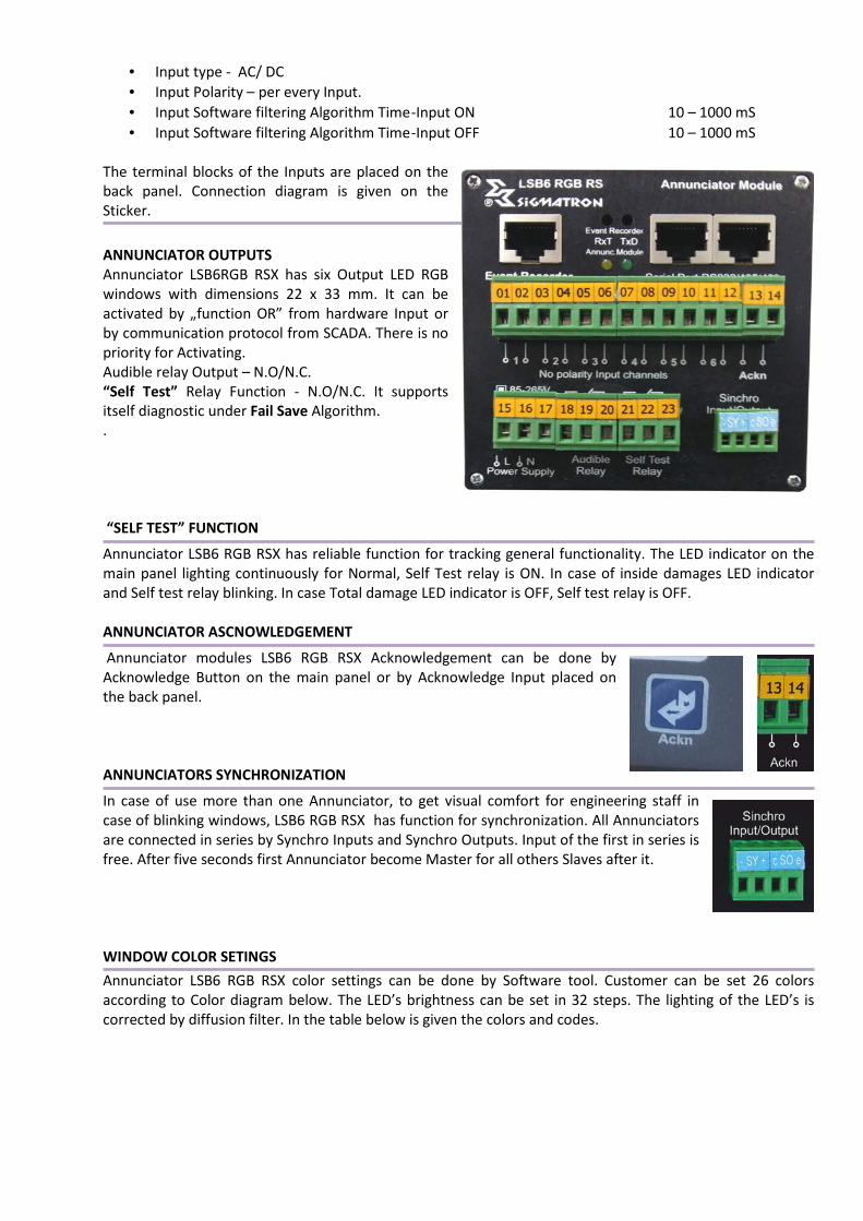
The terminal blocks of the Inputs are placed on the
back panel. Connection diagram is given on the
Sticker.
ANNUNCIATOR OUTPUTS
Annunciator LSB6RGB RSX has six Output LED RGB
windows with dimensions 22 х 33 mm. It can be
activated by „function OR” from hardware Input or
by communication protocol from SCADA. There is no
priority for Activating.
Audible relay Output – N.O/N.C.
“Self Test” Relay Function - N.O/N.C. It supports
itself diagnostic under Fail Save Algorithm.
.
“SELF TEST” FUNCTION
Annunciator LSB6 RGB RSX has reliable function for tracking general functionality. The LED indicator on the
main panel lighting continuously for Normal, Self Test relay is ON. In case of inside damages LED indicator
and Self test relay blinking. In case Total damage LED indicator is OFF, Self test relay is OFF.
ANNUNCIATOR ASCNOWLEDGEMENT
Annunciator modules LSB6 RGB RSX Acknowledgement can be done by
Acknowledge Button on the main panel or by Acknowledge Input placed on
the back panel.
ANNUNCIATORS SYNCHRONIZATION
In case of use more than one Annunciator, to get visual comfort for engineering staff in
case of blinking windows, LSB6 RGB RSX has function for synchronization. All Annunciators
are connected in series by Synchro Inputs and Synchro Outputs. Input of the first in series is
free. After five seconds first Annunciator become Master for all others Slaves after it.
WINDOW COLOR SETINGS
Annunciator LSB6 RGB RSX color settings can be done by Software tool. Customer can be set 26 colors
according to Color diagram below. The LED’s brightness can be set in 32 steps. The lighting of the LED’s is
corrected by diffusion filter. In the table below is given the colors and codes.
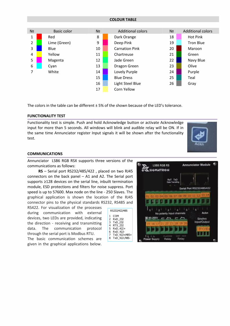
COLOUR TABLE
№ Basic color
№ Additional colors
№ Additional colors
1
Red
8
Dark Orange
18
Hot Pink
2
Lime (Green)
9
Deep Pink
19
Tron Blue
3
Blue
10
Carnation Pink
20
Maroon
4
Yellow
11
Chartreuse
21
Green
5
Magenta
12
Jade Green
22
Navy Blue
6
Cyan
13
Dragon Green
23
Olive
7
White
14
Lovely Purple
24
Purple
15
Blue Dress
25
Teal
16
Light Steel Blue
26
Gray
17
Corn Yellow
The colors in the table can be different ± 5% of the shown because of the LED’s tolerance.
FUNCTIONALITY TEST
Functionality test is simple. Push and hold Acknowledge button or activate Acknowledge
input for more than 5 seconds. All windows will blink and audible relay will be ON. If in
the same time Annunciator register Input signals it will be shown after the functionality
test.
COMMUNICATIONS
Annunciator LSB6 RGB RSX supports three versions of the
communications as follows:
RS – Serial port RS232/485/422 , placed on two RJ45
connectors on the back panel – A1 and A2. The Serial port
supports ≥128 devices on the serial line, inbuilt termination
module, ESD protections and filters for noise suppress. Port
speed is up to 57600. Max node on the line - 250 Slaves. The
graphical application is shown the location of the RJ45
connector pins to the physical standards RS232, RS485 and
RS422. For visualization of the processes
during communication with external
devices, two LEDs are provided, indicating
the direction - receiving and transmitting
data. The communication protocol
through the serial port is Modbus RTU.
The basic communication schemes are
given in the graphical applications below.
RS232/422/485
1 COM
2 RxD_232
3 TxD_232 4 RTS_232
5 RxD_422+
6 RxD_422- 7 TxD_422+/485+
8 TxD_422-/485-

Node 1 Node 2 Node 3 Node 250
Serial line RS485/422
SCADA
Serial Port RS485/422
RSE - Serial port RS232/485/422 , placed on two RJ45
connectors on the back panel – A1 and A2. The Serial port
supports ≥128 devices on the serial line, inbuilt termination
module, ESD protections and filters for noise suppress. Port
speed is up to 57600. Max node on the line - 250 Slaves.
The graphical application is shown the location of the RJ45
connector pins to the physical standards RS232, RS485 and
RS422. For visualization of the processes during
communication with external devices, two LEDs are
provided, indicating the direction - receiving and
transmitting data. The communication protocol through the
serial port is Modbus RTU.
The LAN Port supports Protocols: IP, TCP, UDP, DHCP, DNS,
HTTP, ARP, ICMP, Web socket, HTTPD Client, Modbus TCP
Global MAC address IEEE. defined MAC address
Speed - 600 bps – 1024K bps
Data Format - 5, 6, 7, 8 bits, Stop bits 1, 2, Parity, None, Even, Odd, Space, Mark.
Bidirectional Internal connection LAN to Serial Port
The basic communication schemes of the RSE version are given in the graphical applications below.
Node 1 Node 2 Node 3 Node 250
Serial line RS485/422
SCADA
Serial Port RS485/422

Router
Node 1 Node 2 Node 3 Node 250
Serial line RS485/422
LAN
RSWЕЕ - Serial port RS232/485/422 , placed on two RJ45
connectors on the back panel – A1 and A2. The Serial port
supports ≥128 devices on the serial line, inbuilt
termination module, ESD protections and filters for noise
suppress. Port speed is up to 57600. Max node on the line
- 250 Slaves. The graphical application is shown the
location of the RJ45 connector pins to the physical
standards RS232, RS485 and RS422. For visualization of
the processes during communication with external
devices, two LEDs are provided, indicating the direction -
receiving and transmitting data. The communication
protocol through the serial port is Modbus RTU.
WiFi router + 2 x LAN Ports.
Internal ceramic or external Antenna.
Range up to 200m
The version RSWEE supports Serial to LAN/Wi-Fi, LAN to
Wi-Fi or LAN to LAN transmission.
Bidirectional Internal connection LAN to Serial Port
Modbus RTU to Modbus TCP.
IEEE802.11b/g/n Wireless Standards
TCP/IP/UDP Network Protocols Wireless Network Type AP / Station / AP+Station
Security Mechanism WEP/WPA-PSK/WPA2-PSK
Support Web page Configuration Encryption Type WEP64/WEP128/TKIP/AES
Work Mode Transparent Transmission, Serial Command
Router/Bridge Mode Networking Setting Command AT+instruction set
Support Work As STA/AP/AP+STA Mode, Max TCP connections – 32.
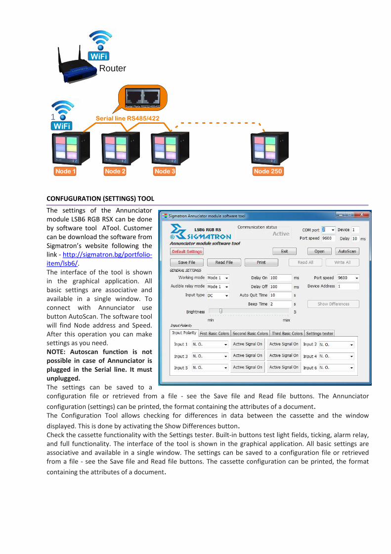
The basic communication schemes of the RSWEE version are given in the graphical applications below.
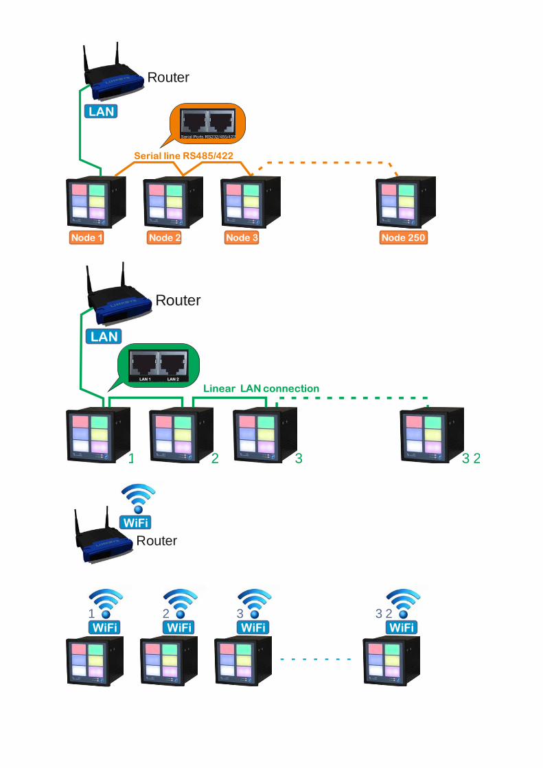
Router
Node 1 Node 2 Node 3 Node 250
Serial line RS485/422
LAN
R uterо
Linear LAN connection
LAN
1 2 3 3 2
LAN 1 LAN 2
WiFi WiFi WiFi WiFi
WiFi
R uterо
1 2 3 3 2
WiFi
WiFi
Router
1
Node 1 Node 2 Node 3 Node 250
Serial line RS485/422
CONFUGURATION (SETTINGS) TOOL
The settings of the Annunciator
module LSB6 RGB RSX can be done
by software tool ATool. Customer
can be download the software from
Sigmatron’s website following the
link - http://sigmatron.bg/portfolio-
item/lsb6/.
The interface of the tool is shown
in the graphical application. All
basic settings are associative and
available in a single window. To
connect with Annunciator use
button AutoScan. The software tool
will find Node address and Speed.
After this operation you can make
settings as you need.
NOTE: Autoscan function is not
possible in case of Annunciator is
plugged in the Serial line. It must
unplugged.
The settings can be saved to a
configuration file or retrieved from a file - see the Save file and Read file buttons. The Annunciator
configuration (settings) can be printed, the format containing the attributes of a document. The Configuration Tool allows checking for differences in data between the cassette and the window
displayed. This is done by activating the Show Differences button. Check the cassette functionality with the Settings tester. Built-in buttons test light fields, ticking, alarm relay,
and full functionality. The interface of the tool is shown in the graphical application. All basic settings are
associative and available in a single window. The settings can be saved to a configuration file or retrieved
from a file - see the Save file and Read file buttons. The cassette configuration can be printed, the format
containing the attributes of a document.

MODBUS RTU ADDRESS REGISTERS
MODBUS ADDRESSES AND VALUE
VERSION LSB 6 V0.1
Address type Description Initial value Note
2000 1 reg int Input type 0-DC,1-AC 0 DC – 0
AC - 1
2001 1 reg int DELAY_ON_TIME: 10 - 1000 ms 100
2002 1 reg int DELAY_OFF_TIME: 10 - 1000 ms 100
2003 1 reg int ALARM_RELAY Function:0,1,2,3 0 See Chapter
FUNCTIONAL MODES OF
THE AUDIBLE RELAY
2004 1 reg int AUTO_QUIT_TIME: 1 - 60 s 10
2005 1 reg int BEEP_TIME: 1 - 5 s 2
2006 1 reg int REACTION_TYPE: 0, 1, 2 0
2007 1 reg int INPUT_LEVEL_1: 0-ON, 1 - OFF 0
2008 1 reg int INPUT_LEVEL_2: 0-ON, 1 - OFF 0
2009 1 reg int INPUT_LEVEL_3: 0-ON, 1 -OFF 0
2010 1 reg int INPUT_LEVEL_4: 0-ON, 1 - OFF 0
2011 1 reg int INPUT_LEVEL_5: 0-ON, 1 - OFF 0
2012 1 reg int INPUT_LEVEL_6: 0-ON, 1 - OFF 0
2013 1 reg int COLOR_1_1 26 First basic - White
2014 1 reg int COLOR_2_1 18 Second basic - Green
2015 1 reg int COLOR_3_1 24 Third basic - Yellow
2016 1 reg int COLOR_1_2 26 First basic - White
2017 1 reg int COLOR_2_2 18 Second basic - Green
2018 1 reg int COLOR_3_2 24 Third basic - Yellow
2019 1 reg int COLOR_1_3 26 First basic - White
2020 1 reg int COLOR_2_3 18 Second basic - Green
2021 1 reg int COLOR_3_3 24 Third basic - Yellow
2022 1 reg int COLOR_1_4 26 First basic - White
2023 1 reg int COLOR_2_4 18 Second basic - Green
2024 1 reg int COLOR_3_4 24 Third basic - Yellow
2025 1 reg int COLOR_1_5 26 First basic - White
2026 1 reg int COLOR_2_5 18 Second basic - Green
2027 1 reg int COLOR_3_5 24 Third basic - Yellow
2028 1 reg int COLOR_1_6 26 First basic - White
2029 1 reg int COLOR_2_6 18 Second basic - Green
2030 1 reg int COLOR_3_6 24 Third basic - Yellow
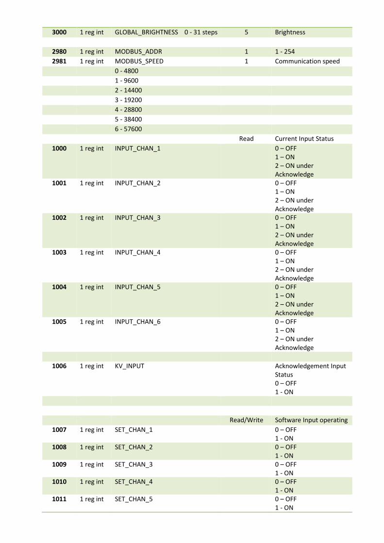
3000 1 reg int GLOBAL_BRIGHTNESS 0 - 31 steps 5 Brightness
2980 1 reg int MODBUS_ADDR 1 1 - 254
2981 1 reg int MODBUS_SPEED 1 Communication speed
0 - 4800
1 - 9600
2 - 14400
3 - 19200
4 - 28800
5 - 38400
6 - 57600
Read Current Input Status
1000 1 reg int INPUT_CHAN_1 0 – OFF
1 – ON
2 – ON under
Acknowledge
1001 1 reg int INPUT_CHAN_2 0 – OFF
1 – ON
2 – ON under
Acknowledge 1002 1 reg int INPUT_CHAN_3 0 – OFF
1 – ON
2 – ON under
Acknowledge 1003 1 reg int INPUT_CHAN_4 0 – OFF
1 – ON
2 – ON under
Acknowledge
1004 1 reg int INPUT_CHAN_5 0 – OFF
1 – ON
2 – ON under
Acknowledge
1005 1 reg int INPUT_CHAN_6 0 – OFF
1 – ON
2 – ON under
Acknowledge
1006 1 reg int KV_INPUT Acknowledgement Input
Status
0 – OFF
1 - ON
Read/Write Software Input operating
1007 1 reg int SET_CHAN_1 0 – OFF
1 - ON
1008 1 reg int SET_CHAN_2 0 – OFF
1 - ON
1009 1 reg int SET_CHAN_3 0 – OFF
1 - ON
1010 1 reg int SET_CHAN_4 0 – OFF
1 - ON
1011 1 reg int SET_CHAN_5 0 – OFF
1 - ON
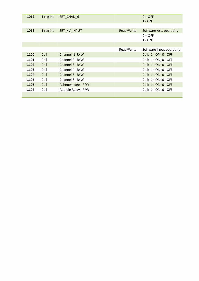
1012 1 reg int SET_CHAN_6 0 – OFF
1 - ON
1013 1 reg int SET_KV_INPUT Read/Write Software Asc. operating
0 – OFF
1 - ON
Read/Write Software Input operating
1100 Coil Channel 1 R/W Coil: 1 - ON, 0 - OFF
1101 Coil Channel 2 R/W Coil: 1 - ON, 0 - OFF
1102 Coil Channel 3 R/W Coil: 1 - ON, 0 - OFF 1103 Coil Channel 4 R/W Coil: 1 - ON, 0 - OFF 1104 Coil Channel 5 R/W Coil: 1 - ON, 0 - OFF 1105 Coil Channel 6 R/W Coil: 1 - ON, 0 - OFF 1106 Coil Achnowledge R/W Coil: 1 - ON, 0 - OFF
1107 Coil Audible Relay R/W Coil: 1 - ON, 0 - OFF
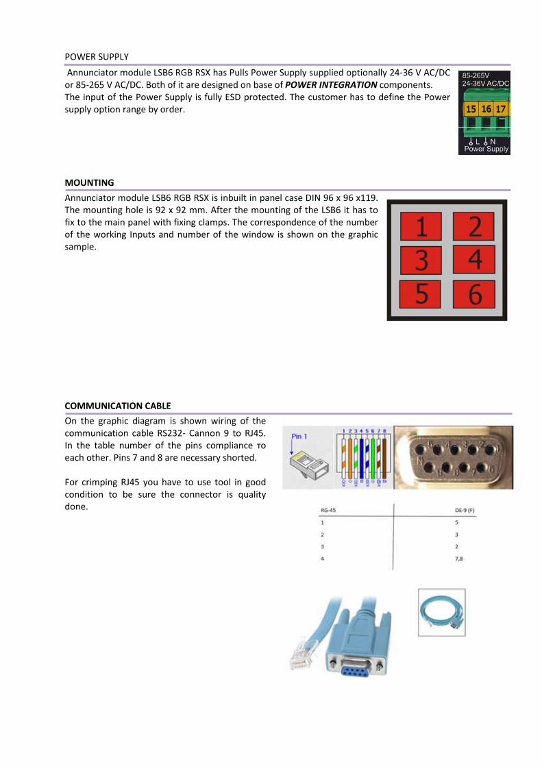
POWER SUPPLY
Annunciator module LSB6 RGB RSX has Pulls Power Supply supplied optionally 24-36 V AC/DC
or 85-265 V AC/DC. Both of it are designed on base of POWER INTEGRAТION components.
The input of the Power Supply is fully ESD protected. The customer has to define the Power
supply option range by order.
MOUNTING
Annunciator module LSB6 RGB RSX is inbuilt in panel case DIN 96 х 96 х119.
The mounting hole is 92 х 92 mm. After the mounting of the LSB6 it has to
fix to the main panel with fixing clamps. The correspondence of the number
of the working Inputs and number of the window is shown on the graphic
sample.
COMMUNICATION CABLE
On the graphic diagram is shown wiring of the
communication cable RS232- Cannon 9 to RJ45.
In the table number of the pins compliance то
each other. Pins 7 and 8 are necessary shorted.
For crimping RJ45 you have to use tool in good
condition to be sure the connector is quality
done.
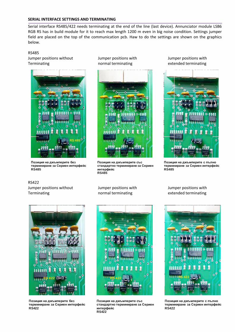
SERIAL INTERFACE SETTINGS AND TERMINATING
Serial interface RS485/422 needs terminating at the end of the line (last device). Annunciator module LSB6
RGB RS has in build module for it to reach max length 1200 m even in big noise condition. Settings jumper
field are placed on the top of the communication pcb. Haw to do the settings are shown on the graphics
below.
RS485
Jumper positions without Jumper positions with Jumper positions with
Terminating normal terminating extended terminating
RS422
Jumper positions without Jumper positions with Jumper positions with
Terminating normal terminating extended terminating
Позиция на джъмперите без терминиране за Сериен интерфейс
22RS4
Позиция на джъмперите със стандартно терминиране за Сериен интерфейс
22RS4
Позиция на джъмперите с пълно терминиране за Сериен интерфейс
422RS
RS 422 RS 422 RS 422
RS 485
Позиция на джъмперите без терминиране за Сериен интерфейсRS485
Позиция на джъмперите със стандартно терминиране за Сериен интерфейсRS485
Позиция на джъмперите с пълно терминиране за Сериен интерфейс
RS485

SPECIFICATIONS
Operating Inputs Six - no polarity
Input activation* Potential signal - 10 -265 V AC/DC – By custom order
No potential – inside voltage 24V DC
Receive Input Signal Time 10 – 1000 mS for DС Input signals
50-1000 mS for АС Input signals
Identifying Signal Software Algorithm
ESD Input protection Varistors
Range of protection 8-20 µS
Energy absorbing 10 J
Threshold protection Yes – for potential Inputs mode
Threshold range 0 - 130 V (for Input 220V)
Asc. / Test Input Potential/No potential Input
Acknowledgement button* On the main panel
Terminal blocks 2.5 mm2 -
Relay Outputs 2 pcs. - 2А/250 V
Lighting windows 6 pcs. LED RGB
Lighting windows dimensions 22 х 33 mm
Lighting windows colors 26
Serial ports RS232/485/422
LAN ports RSE – 1, RSWEE - 2
Connectors Серийни портове - 2 x RJ45, LAN – 1 или 2 x RJ45
Communication Protocols Modbus RTU / Slave, Modbus TCP Client/Server
Power Supply 85-265V AC/DC or 24/36 V AC/DC – By order
Max Power Consumption 6 VA
Working temperature - 10 ÷ 70 оС
Storage temperature - 20 ÷ 80 оС
Humidity 0 ÷ 90 % without condense
Device dimensions without terminal blocks DIN – 96 х 96 х 119 mm
Mounting whole 92х92 mm
Fixing method Fixing clamps – two pcs.
Case material РС – glass mixed, no flammable
Protection Class IP45 Front panel, IP25 back panel
Long term operation More than 15 year under operating requirements.
* Type of the Inputs – potential/no potential, Working Input voltage and type of the Power supply have to be
define in the Customer order.
ORDER FORM
LSB6 RGB - RSX – A – B – CCC
RS Interface Serial RS232/485/422
RSE Serial RS232/485/422+ LAN port
RSWEE Serial RS232/485/422+ WiFi + 2 LAN ports
A - 1 Power Supply 80-265V AC/DC
2 24-36V AC/DC
B – 1 Input type Potential
2 No Potential
CCC Input voltage 10 – 265V, If no potential put 000
СТАНДАРТИ
ЕМС БДС EN 61326, БДС EN 61000-4-2, БДС EN 61000-4-4, БДС EN 61000-4-5,
БДС EN 61000-4-6, БДС EN 61000-4-11
Safety БДС EN 60950(:2000) :2002
Communication ISO/IEC 8482, ANSI/TIA/EIA-422-B, Modbus RTU, Modbus TCP
SMT technology ECSS-Q-ST-70-38C (2008). High-reliability soldering for surface-mount and
mixed technology.
Mechanical IEC 61554
Safety UL94 V0