LRFD- Steel Design. Chapter 6 6.1 INTRODUCTION Most beams and columns are subjected to some degree...
30
LRFD LRFD - - Steel Design Steel Design
-
Upload
elfreda-short -
Category
Documents
-
view
217 -
download
2
Transcript of LRFD- Steel Design. Chapter 6 6.1 INTRODUCTION Most beams and columns are subjected to some degree...

LRFDLRFD--Steel DesignSteel DesignLRFDLRFD--Steel DesignSteel Design

Chapter 6Chapter 6

6.1 INTRODUCTION6.1 INTRODUCTION
Most beams and columns are subjected to some degree of both Most beams and columns are subjected to some degree of both
bending and axial load especially in statically indeterminate bending and axial load especially in statically indeterminate
structures.structures.
Many columns can be treated as pure compression members with Many columns can be treated as pure compression members with
negligible error.negligible error.
For many structural members, there will be a significant amount of For many structural members, there will be a significant amount of
both bending moment and axial load.both bending moment and axial load.
Such members are called beam-column.Such members are called beam-column.
Consider the rigid frame shown in the Figure:Consider the rigid frame shown in the Figure:
For the given loading condition, For the given loading condition,

The horizontal member AB must not only support the vertical The horizontal member AB must not only support the vertical
uniform load but must also assist the vertical members in uniform load but must also assist the vertical members in
resisting the concentrated load Presisting the concentrated load P11..
Member CD is a more critical case, because it must resist the load Member CD is a more critical case, because it must resist the load
PP11 + P + P22 without any assistance from the vertical members. without any assistance from the vertical members.
The reason is that the bracing members, prevents sidesway in the The reason is that the bracing members, prevents sidesway in the
lower story. lower story. (in the direction of P, ED will be in tension and CF will be slack)(in the direction of P, ED will be in tension and CF will be slack)

Member CD must transmit the load PMember CD must transmit the load P11 + P + P22 from C to D. from C to D.
The vertical members of this frame must also be treated as beam-The vertical members of this frame must also be treated as beam-
column.column.
In addition, at A and B, B.M. are transmitted from the horizontal In addition, at A and B, B.M. are transmitted from the horizontal
member through the rigid joints. member through the rigid joints.
This is also occur at C and D and is true in any rigid frame.This is also occur at C and D and is true in any rigid frame.
Most columns in rigid frame are actually beam-columns, and the Most columns in rigid frame are actually beam-columns, and the
effects of bending should not be ignored.effects of bending should not be ignored.
Another example of beam-column can sometimes be found in roof Another example of beam-column can sometimes be found in roof
trusses if purlins are placed between the joints of the top chord. trusses if purlins are placed between the joints of the top chord.

6.2 INTRODUCTION FORMULAS6.2 INTRODUCTION FORMULAS
The inequality Equation may be written in the following form:The inequality Equation may be written in the following form:
If both bending and axial compression are acting the interaction If both bending and axial compression are acting the interaction
formula would beformula would be
WhereWhere
PPuu is the factored axial compressive load. is the factored axial compressive load.
ФФcc P Pnn is the compressive design strength. is the compressive design strength.
MMuu is the factored bending moment. is the factored bending moment.
ФФcc M Mnn is the flexural design strength. is the flexural design strength.
1.0resistance
effectsload
φR
Qγ
n
ii
1.0Mφ
M
Pφ
p
nb
u
nc
u

For biaxial bending, there will be two bending ratios:For biaxial bending, there will be two bending ratios:
Two formulas are given in the specification:Two formulas are given in the specification:
One for small axial load and one for large axial load.One for small axial load and one for large axial load.
1.0Mφ
M
Mφ
M
Pφ
p
nyb
uy
b
ux
nc
u
nx
1.0Mφ
M
Mφ
M
P2φ
p
Pφ
1.0Mφ
M
Mφ
M
Pφ
p
Pφ
nyb
uy
b
ux
nc
u
nc
nyb
uy
b
ux
nc
u
nc
nx
u
nx
u
PFor
PFor
2.0
9
8
2.0

Example 6.1Example 6.1
Determine whether the member shown in the Figure satisfies the Determine whether the member shown in the Figure satisfies the
appropriate AISC Specification interaction equation if the bending appropriate AISC Specification interaction equation if the bending
is about the strong axis.is about the strong axis.
Solution:Solution:
From the column load tables:From the column load tables:
ФФcc P Pn n = 382 kips.= 382 kips.
Since bending is about the strong axis,Since bending is about the strong axis,
ФФbb M Mn n for Cfor Cb b can be obtained from the beam can be obtained from the beam
Design chart in Part 5 of the Manual.Design chart in Part 5 of the Manual.
For LFor Lbb = 17 ft, = 17 ft, ФФbb M Mn n = 200 ft.kips. For the end condition and loading = 200 ft.kips. For the end condition and loading
of this problem, Cof this problem, Cb b = 1.32.= 1.32.

ФФbb M Mn n = C= Cb b * 200 = 1.32 * 200 = 264.0 ft-kips.* 200 = 1.32 * 200 = 264.0 ft-kips.
This moment is larger than This moment is larger than ФФbb M Mp p = 227 ft-kips (also from Manual)= 227 ft-kips (also from Manual)
So the design moment must be limited to So the design moment must be limited to ФФbb M Mp.p. Therefore, Therefore,
ФФbb M Mn n = 227 ft-kips.= 227 ft-kips.
Max. B.M. occurs at midheight, so Max. B.M. occurs at midheight, so MMu u = 25*17/4 = 106.3 ft-kips.= 25*17/4 = 106.3 ft-kips.
Determine which interaction equation controls:Determine which interaction equation controls:
This member satisfies the AISC Specification.This member satisfies the AISC Specification.
1.00106.3
382
200
Mφ
M
Mφ
M
Pφ
p
Pφ
nyb
uy
b
ux
nc
u
nc
94.02279
8
9
8
2.005236382
200
nx
uP

6.3 MOMENT AMPLIFICATION6.3 MOMENT AMPLIFICATION
The presence of the axial load produces secondary moment.The presence of the axial load produces secondary moment.
The total moment =The total moment =P
8
2wL
The second term may be neglected if P is small.The second term may be neglected if P is small.
Because the total deflection cannot be found Because the total deflection cannot be found
directly, this problem is nonlinear, and without directly, this problem is nonlinear, and without
knowing the deflection, we cannot compute the knowing the deflection, we cannot compute the
moment.moment.
Ordinary structural analysis methods that do not take the displaced into Ordinary structural analysis methods that do not take the displaced into
account are referred to as first-order methods.account are referred to as first-order methods.
Iterative numerical techniques, called second-order methods, can be Iterative numerical techniques, called second-order methods, can be
used to find the deflection and secondary moments. used to find the deflection and secondary moments.

These method are usually implemented with a computer program. These method are usually implemented with a computer program.
Most current design codes permit the use of either a second-order Most current design codes permit the use of either a second-order
analysis or the moment analysis or the moment amplification method.amplification method.
This method entails computing the maximum B.M. resulting from This method entails computing the maximum B.M. resulting from
flexural loading by a first-order analysis, then multiplying it by a flexural loading by a first-order analysis, then multiplying it by a
moment amplification factor to account for the secondary moment amplification factor to account for the secondary
moment.moment.
Where, MWhere, M00 is the unamplified maximum moment. is the unamplified maximum moment.
PPee is the Euler buckling load = and P is the Euler buckling load = and Puu is factored load. is factored load.
)eu
0max /P(P1
1MM
2
2
(kL)
EIπ

As we describe later, the exact form of the AISC moment As we describe later, the exact form of the AISC moment amplification factor can be slightly different.amplification factor can be slightly different.
Example 6.2. Example 6.2. Compute the amplification factor for the beam-Compute the amplification factor for the beam-column of example 6.1. column of example 6.1.
This represents a 12 % increase in B.M.This represents a 12 % increase in B.M.
MMmaxmax = 1.12 * 106.3 = 119 ft-kips = 1.12 * 106.3 = 119 ft-kips
kips187412)/4.35)*(17*(1.0
14.4*29000*πP
(kL/r)
EAπ
(kL)
EIπP
2
2
e
2
2
2
2
e
1.12(200/1874)1
1factorAmp.
)/P(P1
1factorionAmplificat
eu

6.4 WEB LOCAL BUCKLING IN BEAM-COLUMNS6.4 WEB LOCAL BUCKLING IN BEAM-COLUMNS
The determination of the design moment requires that the cross The determination of the design moment requires that the cross
section be checked for compactness.section be checked for compactness.
The web is compact for all tabulated shapes if there is no axial load.The web is compact for all tabulated shapes if there is no axial load.
If λ ≤ λIf λ ≤ λpp, the shape is compact, the shape is compact
If λIf λpp ≤ λ ≤ λ ≤ λ ≤ λrr, the shape is noncompact; and, the shape is noncompact; and
If λIf λrr ≤ λ, the shape is slender ≤ λ, the shape is slender
AISC B5, Table 5.1, prescribes the following limits:AISC B5, Table 5.1, prescribes the following limits:
. .
yb
u
yp
yb
u
Pφ
2.75P1
F
E3.76λ0.125,
Pφ
PFor

yyb
u
yp
yb
u
FPφ
P2
F
E.λ0.125,
Pφ
PFor
E49.133.121
For any value ofFor any value of
Where PWhere Pyy = A = Agg F Fyy
Because PBecause Pyy is variable, compactness of the web cannot be is variable, compactness of the web cannot be
checked and tabulated. checked and tabulated.
Some rolled shapes satisfy the worst case limit of Some rolled shapes satisfy the worst case limit of
Shapes listed in the column load tables in Part 4 of the Manual Shapes listed in the column load tables in Part 4 of the Manual
that do not satisfy this criterion are marked, and these shapes that do not satisfy this criterion are marked, and these shapes
need to be checked for compactness of the web.need to be checked for compactness of the web.
Shapes whose flanges are not compact are also marked Shapes whose flanges are not compact are also marked
yb
u
yr
yb
u
Pφ
P
F
Eλ,
Pφ
P74.00.170.5
yFE /49.1

Example 6.3Example 6.3A W12 x 58 of A992 steel is subjected to a bending moment A W12 x 58 of A992 steel is subjected to a bending moment
and a factored axial load of 300 kips. Check the web for and a factored axial load of 300 kips. Check the web for compactness. compactness.
The upper limit is The upper limit is
From the dimension and properties tables From the dimension and properties tables λλ = h/t = h/tw w = 27.0 < λ= 27.0 < λpp
The web is therefore compactThe web is therefore compact
0.125Aφ
P
Pφ
P
b
u
yb
u 3922.050*0.17*90.0
300
ygF
27.523922.33.12133.121
02
50
29000.
Pφ
P2
F
E.λ
yb
u
yp
27.5227.5288.3529000
49.149.1 p
E 50Fy

6.5 BRACED VERSUS UNBRACED FRAMES6.5 BRACED VERSUS UNBRACED FRAMES
Two amplification factors are used in LRFDTwo amplification factors are used in LRFD
One to account for amplification resulting from the member deflection and the other to One to account for amplification resulting from the member deflection and the other to
account for the effect of sway when the member is part of unbraced frame. The following account for the effect of sway when the member is part of unbraced frame. The following
Figure illustrates these two components.Figure illustrates these two components.
. .
In Figure a, the member is restrained against In Figure a, the member is restrained against
sidesway, and the max. secondary moment is Psidesway, and the max. secondary moment is Pδδ..
If the frame is unbraced, there is an additional If the frame is unbraced, there is an additional
component of the secondary moment, shown in component of the secondary moment, shown in
Figure b, and the max value of it is PFigure b, and the max value of it is PΔΔ, which , which
represents an amplification of the end moment.represents an amplification of the end moment.

The amplified moment to be used in design is:The amplified moment to be used in design is:
MMuu = B = B11 M Mntnt + B + B22 M Mltlt
WhereWhere
MMnt nt = maximum moment assuming that no sidesway occurs.= maximum moment assuming that no sidesway occurs.
MMltlt = maximum moment caused by sidesway, = 0.0 in the actuall = maximum moment caused by sidesway, = 0.0 in the actuall
braced frame.braced frame.
BB1 1 = amplification factor for the moment occurring in the member = amplification factor for the moment occurring in the member
when it is braced against sidesway.when it is braced against sidesway.
BB2 2 = amplification factor for the moment resulting from sidesway.= amplification factor for the moment resulting from sidesway.
The following sections explain the evaluation of BThe following sections explain the evaluation of B11 and B and B22 . .

6.6 MEMBERS IN BRACED FRAMES6.6 MEMBERS IN BRACED FRAMES
The amplification factor given in section 6.3 was derived for a The amplification factor given in section 6.3 was derived for a
member braced against sidesway.member braced against sidesway.
The following Figure shows a member of this type The following Figure shows a member of this type
Maximum moment amplification occurs at the Maximum moment amplification occurs at the
center, where the deflection is largest.center, where the deflection is largest.
For equal end moment, the moment is constant For equal end moment, the moment is constant
throughout the length of the member, throughout the length of the member,
So the maximum primary moment also occurs at the center.So the maximum primary moment also occurs at the center.
If the end moments are not equal, the maximum primary and If the end moments are not equal, the maximum primary and
secondary moments will occur near each other.secondary moments will occur near each other.

If the end moments produce reverse-curvature bending as shown. If the end moments produce reverse-curvature bending as shown.
Here the max. primary moment is at one of the ends, and the max. Here the max. primary moment is at one of the ends, and the max.
amplification occurs between the ends. amplification occurs between the ends.

Therefore, the max. moment in a beam-column depends on the Therefore, the max. moment in a beam-column depends on the
distribution of bending moment within the member. distribution of bending moment within the member.
This distribution is accounted for by a factor, CThis distribution is accounted for by a factor, Cmm, applied to the , applied to the
amplification factor given in section 6.3.amplification factor given in section 6.3.
The amplification factor given in section 6.3 was derived for the The amplification factor given in section 6.3 was derived for the
worst case, so Cworst case, so Cmm will never be greater than 1.0. will never be greater than 1.0.
The final form of the The final form of the amplification factor isamplification factor is
2
2
1 )/(1
) rKL
EAwhere g
e1e1u
m P/P(P1
CB
Note:Note:
When computing pWhen computing pe1e1, use KL/r for the axis of bending and an effective length , use KL/r for the axis of bending and an effective length
factor K less than or equal to 1.0 (braced condition)factor K less than or equal to 1.0 (braced condition)

Evaluation of CEvaluation of Cmm
The factor Cm applies only to the braced condition. The factor Cm applies only to the braced condition.
There are two categories of members:There are two categories of members:
1.1.Members with transverse loads applied between it’s ends.Members with transverse loads applied between it’s ends.
2.2.Members with no transverse loads.Members with no transverse loads.

If there are no transverse loads acting on the member,If there are no transverse loads acting on the member,
MM11/M/M2 2 is the ratio of the bending moments at the ends of the is the ratio of the bending moments at the ends of the
member. (member. (MM1 1 is the smallest value and Mis the smallest value and M2 2 is the largest one).is the largest one).
The ratio is positive for member bent in reverse curvature and The ratio is positive for member bent in reverse curvature and
negative for single curvature bending as shown in the Figure.negative for single curvature bending as shown in the Figure.
2
14.06.0M
MCm

For transversely loaded members, CFor transversely loaded members, Cmm can be taken as 0.85 if the can be taken as 0.85 if the
ends are restrained against rotation (fixed) and 1.0 if the ends are ends are restrained against rotation (fixed) and 1.0 if the ends are
unrestrained against rotation (pinned). unrestrained against rotation (pinned).
End restrained will usually result from the stiffness of members End restrained will usually result from the stiffness of members
connected to the beam-column.connected to the beam-column.
Although the actual end condition may lie between full fixity and a Although the actual end condition may lie between full fixity and a
frictionless pin, use of one of the two values given here will give frictionless pin, use of one of the two values given here will give
satisfactory results.satisfactory results.

Example 6.5Example 6.5
The horizontal beam-column shows in the Figure is subjected to the The horizontal beam-column shows in the Figure is subjected to the
service live loads shown. This member is laterally braced at its ends, and service live loads shown. This member is laterally braced at its ends, and
bending is about the x-axis. Check for compliance with the AISC bending is about the x-axis. Check for compliance with the AISC
Specification. Specification.
SolutionSolution
The factored load = PThe factored load = Pu u =1.6*28=44.8 kips, w=1.6*28=44.8 kips, wuu=12*0035=0.042 kips=12*0035=0.042 kips
The maximum moment isThe maximum moment is
The member is braced against end translation, so MThe member is braced against end translation, so M ltlt =0.0 =0.0
kipsft112.58
(10)*0042
4
10*44.8M
2
nt
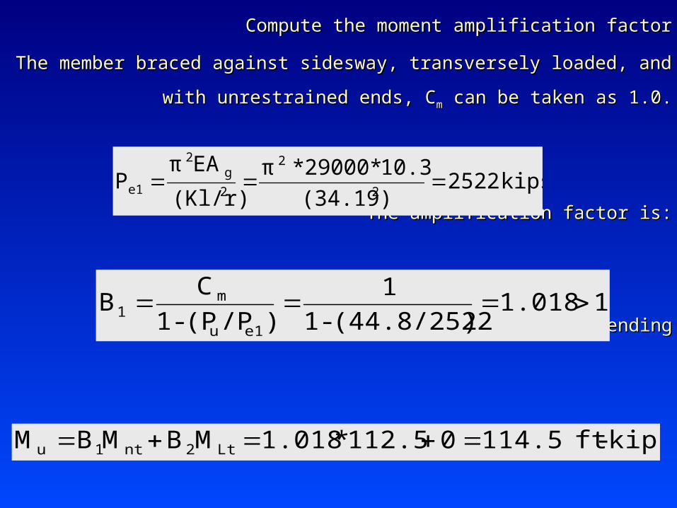
Compute the moment amplification factorCompute the moment amplification factor
The member braced against sidesway, transversely loaded, and with The member braced against sidesway, transversely loaded, and with
unrestrained ends, Cunrestrained ends, Cmm can be taken as 1.0. can be taken as 1.0.
The amplification factor is:The amplification factor is:
For the axis of bendingFor the axis of bending
kips2522(34.19)
10.3*29000*π
(Kl/r)
EAπP
2
2
2
g2
e1
11.018)(44.8/2522-1
1
)/P(P-1
CB
e1u
m1
kips-ft114.50112.5*1.018MBMBM Lt2nt1u

compactisshapethe,pλλsince
9.15250
290000.38
yF
E0.38pλ8.10,
f2t
fbλ
flange the of scompactnes for check first strength, flexural the For
kips339.138.73*10.3*0.85crFgAcφnPcφ
ksi38.73(50)2(0.7813)
(0.658)y)F2cλ
(0.658crF
inelastic1.5cλ
0.781329000
50
π
29.11
E
yF
rπ
KLcλ
59.112.03
12)*1.0(10
yr
LyK
r
KLMaximum

rL
bL
pLSince
ftinrL
yFX
yF
Xyr
rL
ftin
yF
Eyr
pL
ft
09.241.2892)1050)(610*763(11)1050(
3610*03.2
2)10(2
11)10(
1
17.704.8650
2900003.2*76.176.1
10bL
buckling. torsional Lateral

kipsft122.81473*0.9Mφ
kipsin14731024.09
7.17101248)(17351735M
kipsin124831.2*10)(5010)S(FM
kipsin173534.7*50ZFM
)M(MMM
nb
n
yr
yp
rppn
pL
rL
pL
bL
Because the beam weight is very small in relation to the Because the beam weight is very small in relation to the
concentrated live load, Cconcentrated live load, Cbb may be taken from Figure 5.15c as may be taken from Figure 5.15c as
1.32. This value results in a design moment of 1.32. This value results in a design moment of kips162.1ft122.8*1.32Mφ nb

This moment is greater than the plastic moment = 0.90*1735/12 This moment is greater than the plastic moment = 0.90*1735/12
=130.1 ft-kips, so the design strength must be limited to this value.=130.1 ft-kips, so the design strength must be limited to this value.
Check the interaction formula:Check the interaction formula:
adequateis35xW8aSo
(OK)1.00.9430130.1
114.1
2(339.1)
44.8
Mφ
M
Mφ
M
P2φ
P
0.200.1321339.1
44.8
Pφ
P
nyc
uy
nxc
ux
nc
u
nc
u
Please read the remaining examples, 6.4 and 6.6 from the text Please read the remaining examples, 6.4 and 6.6 from the text
book.book.

6.7 MEMBERS IN UNBRACED FRAMES6.7 MEMBERS IN UNBRACED FRAMES
The amplification factor given in section 6.3 was derived for a The amplification factor given in section 6.3 was derived for a
member braced against sidesway.member braced against sidesway.
The following Figure shows a member of this type The following Figure shows a member of this type