Beam-Columns. Members Under Combined Forces Most beams and columns are subjected to some degree of...
32
Beam-Columns
-
date post
22-Dec-2015 -
Category
Documents
-
view
225 -
download
6
Transcript of Beam-Columns. Members Under Combined Forces Most beams and columns are subjected to some degree of...

Beam-Columns

Members Under Combined Forces
Most beams and columns are subjected to some degree of both bending and axial load
e.g. Statically Indeterminate Structures
P1
P2
C
E
A
D
F
B
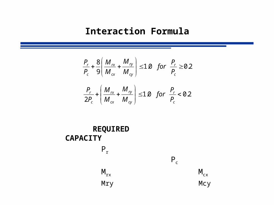
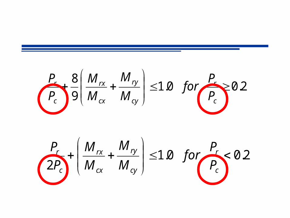
Interaction Formula
REQUIRED CAPACITY
Pr Pc
Mrx Mcx
Mry Mcy
2.0 0.19
8
c
r
cy
ry
cx
rx
c
r
P
Pfor
M
M
M
M
P
P
2.0 0.12
c
r
cy
ry
cx
rx
c
r
P
Pfor
M
M
M
M
P
P
2.0 0.19
8
c
r
cy
ry
cx
rx
c
r
P
Pfor
M
M
M
M
P
P
2.0 0.12
c
r
cy
ry
cx
rx
c
r
P
Pfor
M
M
M
M
P
P
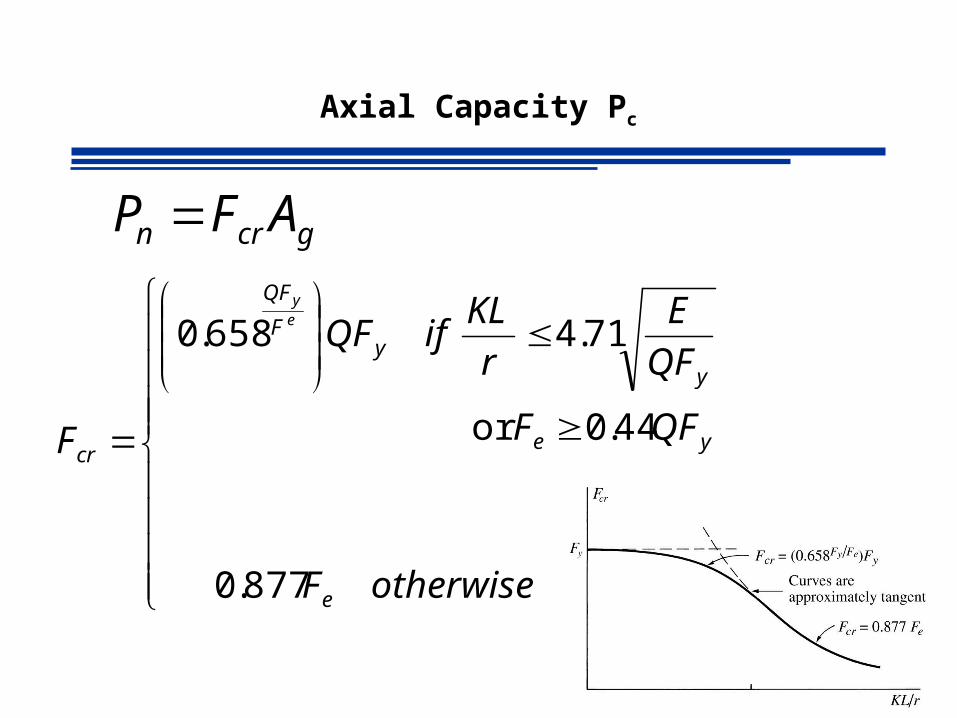
Axial Capacity Pc
877.0
44.0or
71.4 658.0
otherwiseF
QFF
QF
E
r
KLifQF
F
e
ye
yy
F
QF
cr
ey
gcrn AFP

Axial Capacity Pc
Elastic Buckling Stress corresponding to the controlling mode of failure (flexural, torsional or flexural torsional)
Fe:
Theory of Elastic Stability (Timoshenko & Gere 1961)
Flexural Buckling Torsional Buckling2-axis of symmetry
Flexural Torsional Buckling1 axis of symmetry
Flexural Torsional BucklingNo axis of symmetry
22
/ rKL
EFe
AISC EqtnE4-4
AISC EqtnE4-5
AISC EqtnE4-6

Axial Capacity Pc
LRFD
ncc PP
strength ecompressiv design ncP
0.90 ncompressiofor factor resistance c
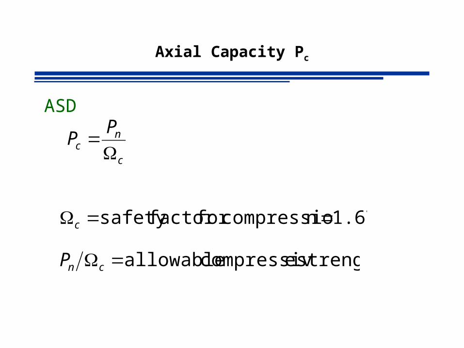
Axial Capacity Pc
ASD
c
nc
PP
strength ecompressiv allowable cnP
1.67 ncompressiofor factor safety c

Moment Capacities
2.0 0.19
8
c
r
cy
ry
cx
rx
c
r
P
Pfor
M
M
M
M
P
P
2.0 0.12
c
r
cy
ry
cx
rx
c
r
P
Pfor
M
M
M
M
P
P
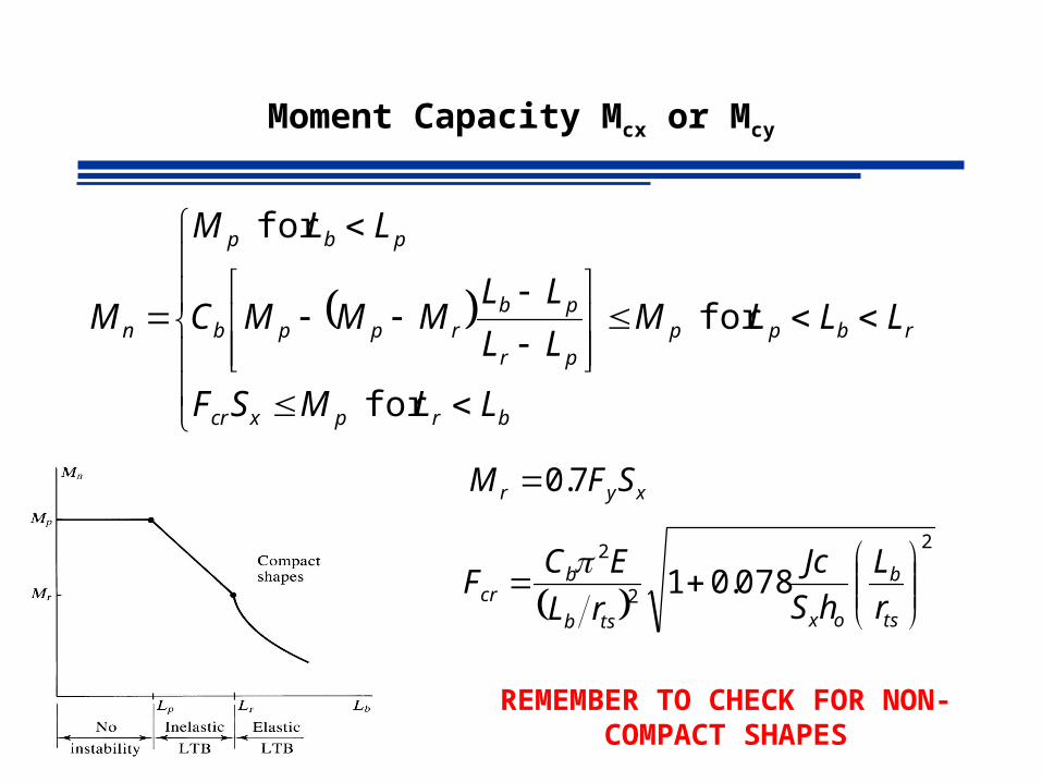
Moment Capacity Mcx or Mcy
2
2
2
078.01
ts
b
oxtsb
bcr r
L
hS
Jc
rL
ECF
rbp
brpxcr
ppr
pbrppb
pbp
n LLL
LLMSF
MLL
LLMMMC
LLM
M
for
for
for
xyr SFM 7.0
REMEMBER TO CHECK FOR NON-COMPACT SHAPES
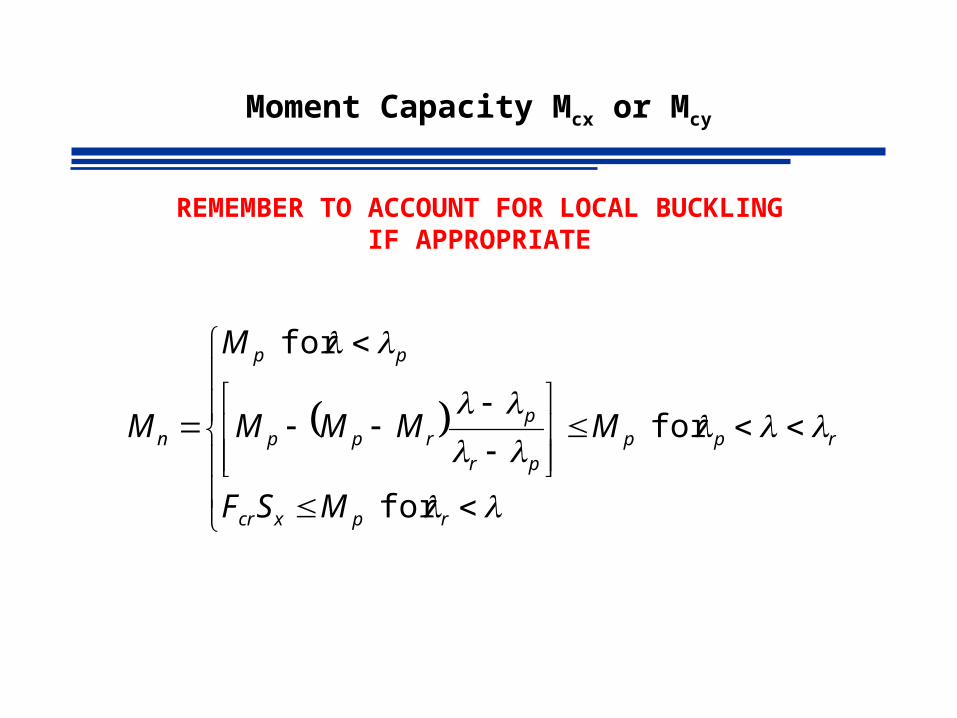
Moment Capacity Mcx or Mcy
rp
rpxcr
ppr
prpp
pp
n
MSF
MMMM
M
M
for
for
for
REMEMBER TO ACCOUNT FOR LOCAL BUCKLING IF APPROPRIATE

Moment Capacity Mcx or Mcy
nbc MM b
nc
MM
LRFD ASD
90.0b 67.1b
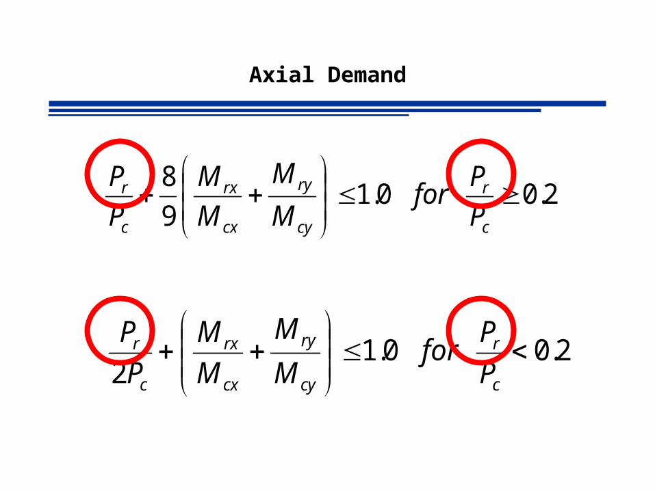
Axial Demand
2.0 0.19
8
c
r
cy
ry
cx
rx
c
r
P
Pfor
M
M
M
M
P
P
2.0 0.12
c
r
cy
ry
cx
rx
c
r
P
Pfor
M
M
M
M
P
P
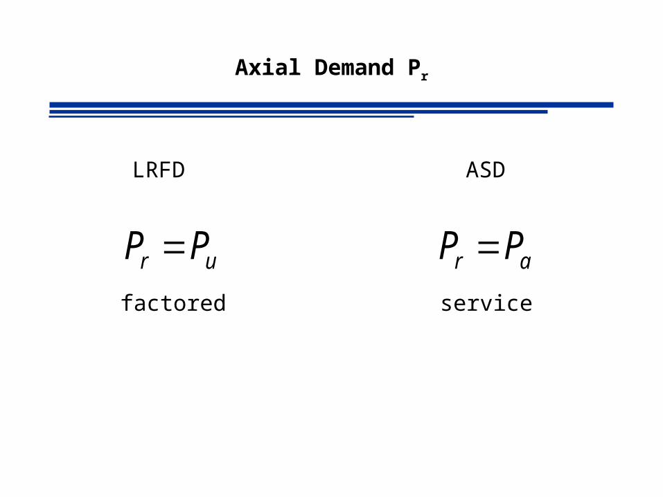
Axial Demand Pr
ur PP
LRFD ASD
ar PP factored service
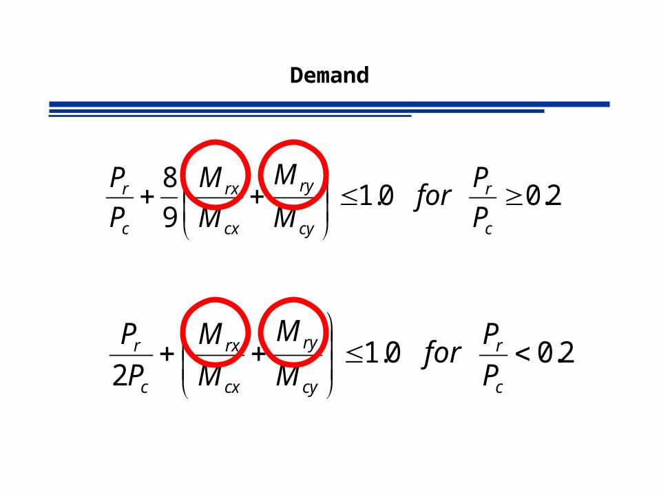
Demand
2.0 0.19
8
c
r
cy
ry
cx
rx
c
r
P
Pfor
M
M
M
M
P
P
2.0 0.12
c
r
cy
ry
cx
rx
c
r
P
Pfor
M
M
M
M
P
P
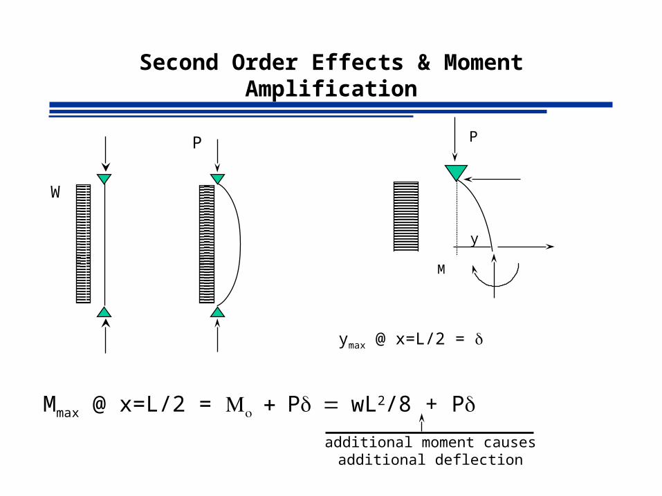
Second Order Effects & Moment Amplification
W
P P
M
y
ymax @ x=L/2 =
Mmax @ x=L/2 = PwL2/8 + P
additional moment causes additional deflection

Second Order Effects & Moment Amplification
Consider
Mmax = P
additional moment causes additional deflection
P
H H
P
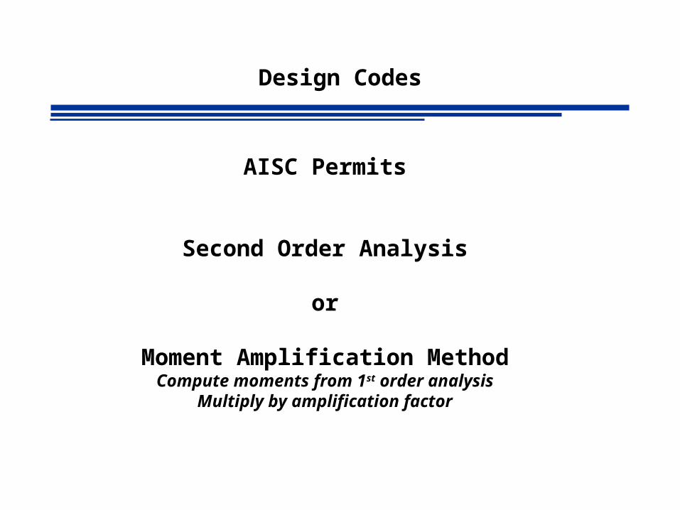
Design Codes
AISC Permits
Second Order Analysis
or
Moment Amplification MethodCompute moments from 1st order analysis
Multiply by amplification factor
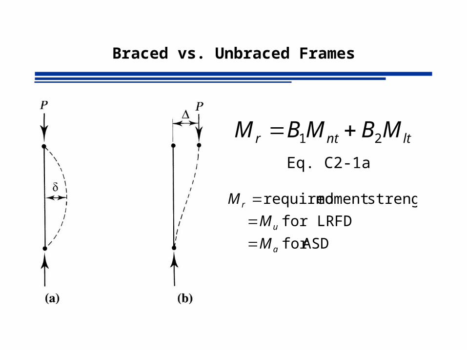
Braced vs. Unbraced Frames
ltntr MBMBM 21
ASDfor
for LRFD
strengthmoment required
a
u
r
M
M
M
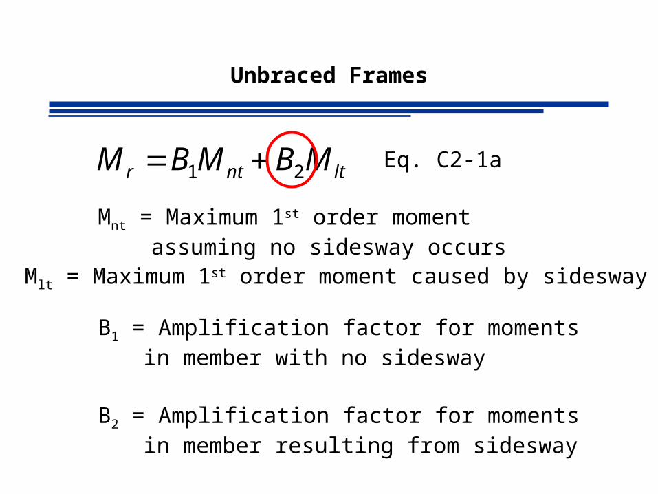
Eq. C2-1a
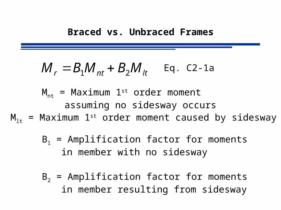
Braced vs. Unbraced Frames
ltntr MBMBM 21 Eq. C2-1a
Mnt = Maximum 1st order moment assuming no sidesway occurs
Mlt = Maximum 1st order moment caused by sidesway
B1 = Amplification factor for moments in member with no sidesway
B2 = Amplification factor for moments in member resulting from sidesway

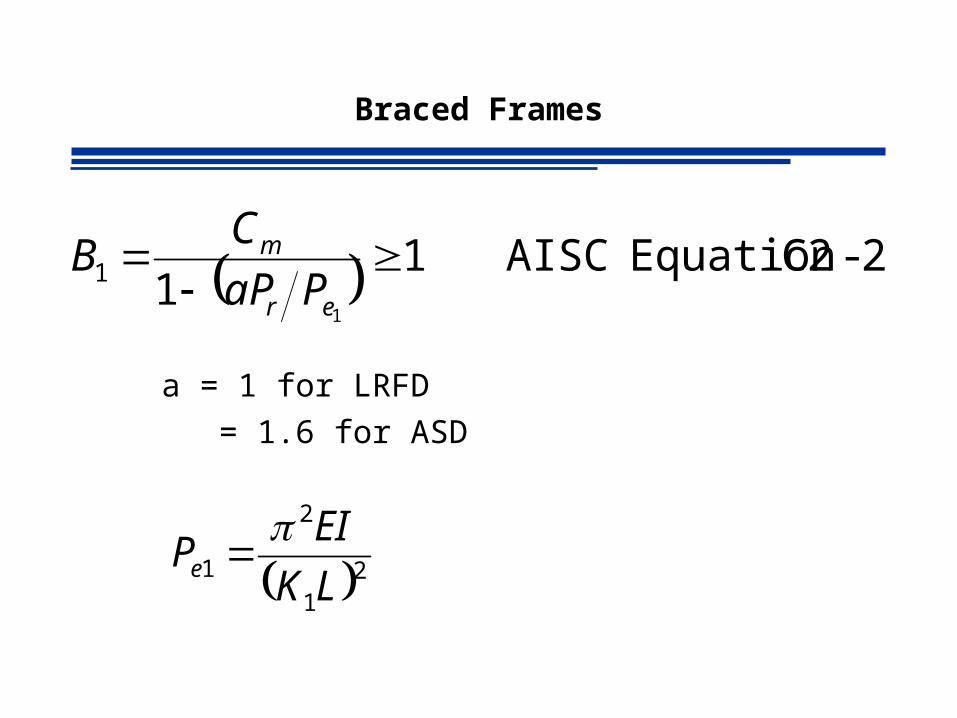
Braced Frames
2-C2 EquationAISC 11
1
1
er
m
PaP
CB
Pr = required axial compressive strength
= Pu for LRFD
= Pa for ASD
Pr has a contribution from the P effect and is given by
ltntr PBPP 2
Braced Frames
2-C2 EquationAISC 11
1
1
er
m
PaP
CB
a = 1 for LRFD
= 1.6 for ASD
21
2
1LK
EIPe
Braced Frames
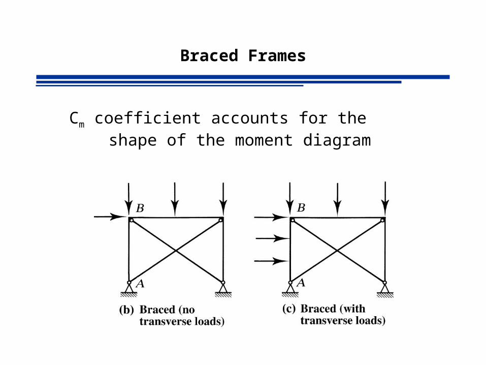
Cm coefficient accounts for the shape of the moment diagram

Braced Frames
Cm For Braced & NO TRANSVERSE LOADS
4-C2 AISC 4.06.02
1
M
MCm
M1: Absolute smallest End Moment
M2: Absolute largest End Moment

Braced Frames
Cm For Braced & NO TRANSVERSE LOADS
2-C2 Commentary AISC 11
e
rm P
aPC
C2.1-C Table Commentary AISC
1-2
2
LM
EI
o
o
COSERVATIVELY Cm= 1
Unbraced Frames
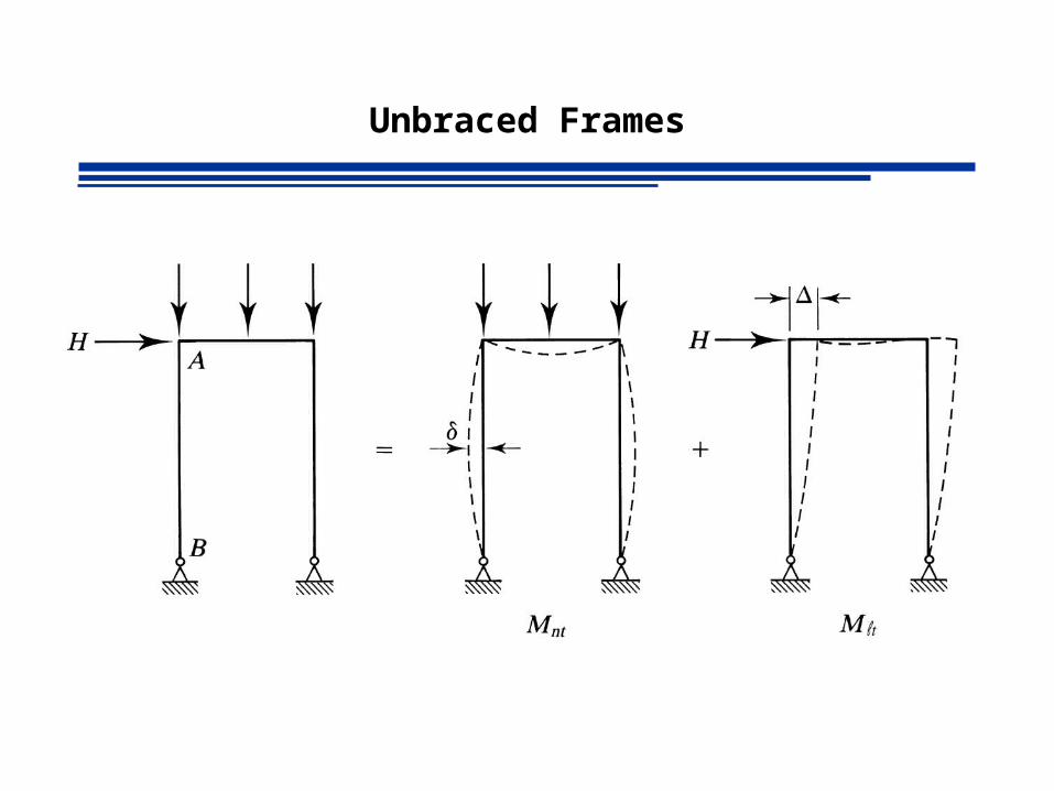
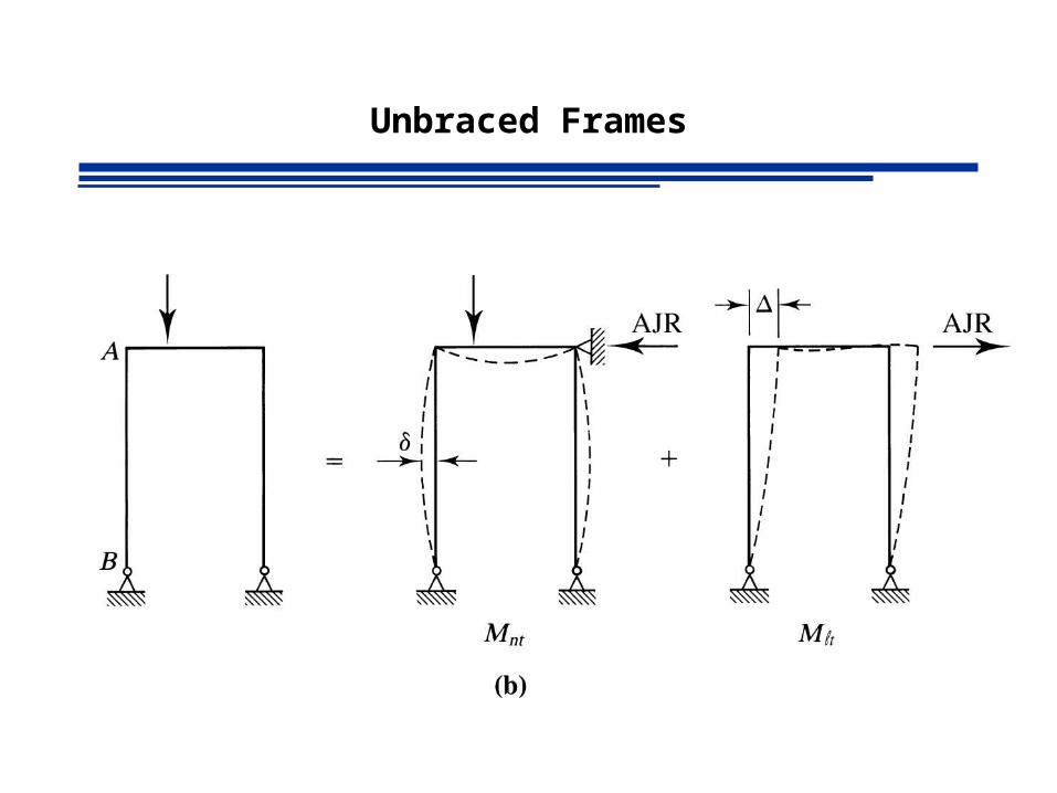
ltntr MBMBM 21 Eq. C2-1a
Mnt = Maximum 1st order moment assuming no sidesway occurs
Mlt = Maximum 1st order moment caused by sidesway
B1 = Amplification factor for moments in member with no sidesway
B2 = Amplification factor for moments in member resulting from sidesway
Unbraced Frames
Unbraced Frames
Unbraced Frames
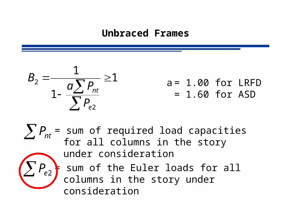
1
1
1
2
2
e
nt
P
PaB a = 1.00 for LRFD
= 1.60 for ASD
ntP = sum of required load capacities for all columns in the story under consideration
2eP = sum of the Euler loads for all columns in the story under consideration

Unbraced Frames
22
2
2LK
EIPe
Hme
HLRP
2
Used when shape is knowne.g. check of adequacy
Used when shape is NOT knowne.g. design of members
Unbraced Frames
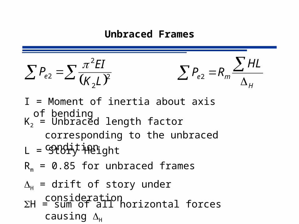
22
2
2LK
EIPe
I = Moment of inertia about axis of bending
Hme
HLRP
2
K2 = Unbraced length factor corresponding to the unbraced condition
L = Story Height
Rm = 0.85 for unbraced frames
H = drift of story under consideration
H = sum of all horizontal forces causing H

Homework
• 6.2-1
• 6.2-2
• 6.5-2
• 6.5-6
• 6.6-1