LPS for Rooftop PV Systems Use - pqrs.co.za
33
14/12/2020 1 Lightning Protection Systems (LPS) for Rooftop Solar PV Safe and effective Lightning Protection Systems (LPS) for Rooftop Solar PV General principles & statistics Lightning formation and characteristics Lightning damages and statistics Simplified risk assessment methodologies What is an effective LPS Air-termination systems (ATS) Down-conductor system (DCS) Earth-termination system (ETS) Lightning equipotential bonding (LEB) Separation distances Update from SABS SANS 10142-1-2 SANS 10313 Certification of installations Practical examples Structures without LPS Structures with isolated LPS Structures without isolated LPS The formation of lightning Down‐ward leaders and up‐ward streamers Interesting facts and figures The formation of lightning Designing effective & safe lightning protection systems (LPS) 1 2 3
Transcript of LPS for Rooftop PV Systems Use - pqrs.co.za
14/12/2020
1
Lightning Protection Systems (LPS) for Rooftop Solar PV
Safe and effective Lightning Protection Systems (LPS) for Rooftop Solar PV
General principles & statistics Lightning formation and characteristics Lightning damages and statistics Simplified risk assessment methodologies
What is an effective LPS Air-termination systems (ATS) Down-conductor system (DCS) Earth-termination system (ETS) Lightning equipotential bonding (LEB) Separation distances
Update from SABS SANS 10142-1-2 SANS 10313 Certification of installations
Practical examples Structures without LPS Structures with isolated
LPS Structures without
isolated LPS
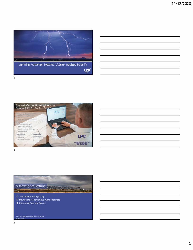
The formation of lightning
Down‐ward leaders and up‐ward streamers
Interesting facts and figures
The formation of lightning
Designing effective & safe lightning protection systems (LPS)
1
2
3

14/12/2020
2
Formation of Lightning
Downward Leaders & Upward Streamers
Downward Leaders & Upward Streamers
4
5
6

14/12/2020
3
Reasons for Lightning Damage
Lightning Safety
Electrothermal Effects• Direct strike• Contact Potential (Touch Voltage)• Side Flash• Step Voltage• Upward Streamer Current
Direct Strike Side Flash Upward Streamer
Step Potential
Contact / Touch Potential
Lightning Safety
Blunt Force Trauma
• Barotrauma
• Concussive Injury
• Musculoskeletal Injury (Muscle Contraction) - falling
Concussive, Explosive Barotrauma• Also called secondary missile injury.
• Injuries caused by flying shrapnel resulting from a direct lightning strike to an object.
• Lightning`s pressure blast can tear or rip off clothing, fracture bones, cause Tympanic Membrane rupture and cause lung concussions
7
8
9

14/12/2020
4
Lightning Safety
Lightning Fatalities
Step Potential50‐55%
Side Flash30‐35%
Upward Streamer10‐15%
Touch Potential3‐5%
Direct Strike3‐5%
Blunt Injury?
Are You Safe?
The image part with relationship ID rId4 was not found in the file.
WHY?
Are You Safe?
10
11
12

14/12/2020
5
Are You Safe?
WHY?
Build the Plane
Faraday Cage
13
14
15
14/12/2020
6
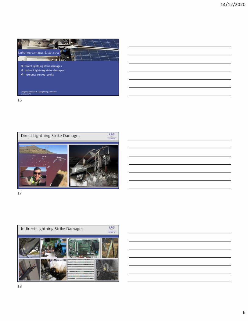
Direct lightning strike damages
Indirect lightning strike damages
Insurance survey results
Lightning damages & statistics
Designing effective & safe lightning protection systems (LPS)
Direct Lightning Strike Damages
source: DEHN
source: DEHN
Indirect Lightning Strike Damages
16
17
18

14/12/2020
7
Sources of Damage to PV Systems
Technical Failure 6% Marten Bite 3%
Malevolence 3%
Theft 2%
Fire 2%
Lightning and Surges
26%
Miscelaneous 32%
Snow Loading 14%
Storms 9%, 9%
The principle of a Risk Assessment
Lightning collection area (new concept)• Solar rooftop vs. Building LPS
Critical vs. Cumulative line length for d.c. & a.c lines• Lightning ground flash density (NG)
Simplified risk methodologies
Designing effective & safe lightning protection systems (LPS)
Risk Assessment Principles
19
20
21

14/12/2020
8
Lightning Collection Area
• The erection of solar systems on or at buildings does not changethe lightning strike risk to the building, which means the equivalentcollection area of the building (Abuilding) remains the same.
• The risk to the solar system can be estimated by calculating theequivalent collection area of the solar system (Asolar) then to usethe formula below to calculate the risk to the solar system only.
𝑹𝒔𝒐𝒍𝒂𝒓 𝑹𝒃𝒖𝒊𝒍𝒅𝒊𝒏𝒈𝑨𝒔𝒐𝒍𝒂𝒓
𝑨𝒃𝒖𝒊𝒍𝒅𝒊𝒏𝒈
• The method of risk assessment is based on the evaluation of the critical length Lcrit and its comparison with L the cumulative length of the d.c. lines.
• SPDs shall be installed on the d.c. side of the installation:
𝑳 𝑳𝒄𝒓𝒊𝒕
DC Lines ‐ Critical Length
AC Lines ‐ Critical Length
• A method of general risk assessment is described in IEC 61662. An essential simplification of this method has been accepted. It is based on the critical length dc
• Protection is required if:
• d is the conventional length in km of the supply line of the considered structure (Max. 1km)
• dc is the critical length; of the incoming lines and the level of consequences
𝒅𝒄𝟏𝑵𝑮
𝒅 𝒅𝒄
𝒅𝒄𝟐𝑵𝑮
consequences to groups of individuals, e.g. large residential buildings, churches, offices, schools;
consequences to individuals, e.g. residential buildings, small offices.;
22
23
24
14/12/2020
9
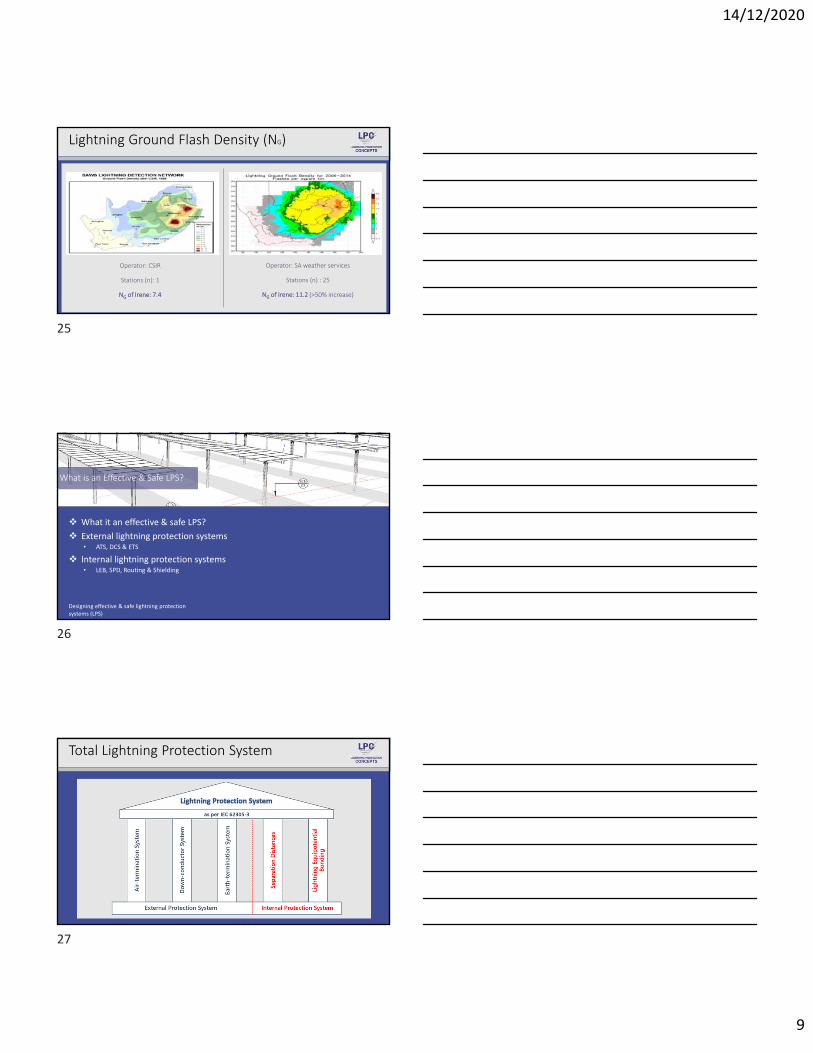
Lightning Ground Flash Density (NG)
• Notes:
• Single station in SA
• NG of Irene => 7‐8
Operator: SA weather services
Stations (n) : 25
NG of Irene: 11.2 (>50% increase)
Operator: CSIR
Stations (n): 1
NG of Irene: 7.4
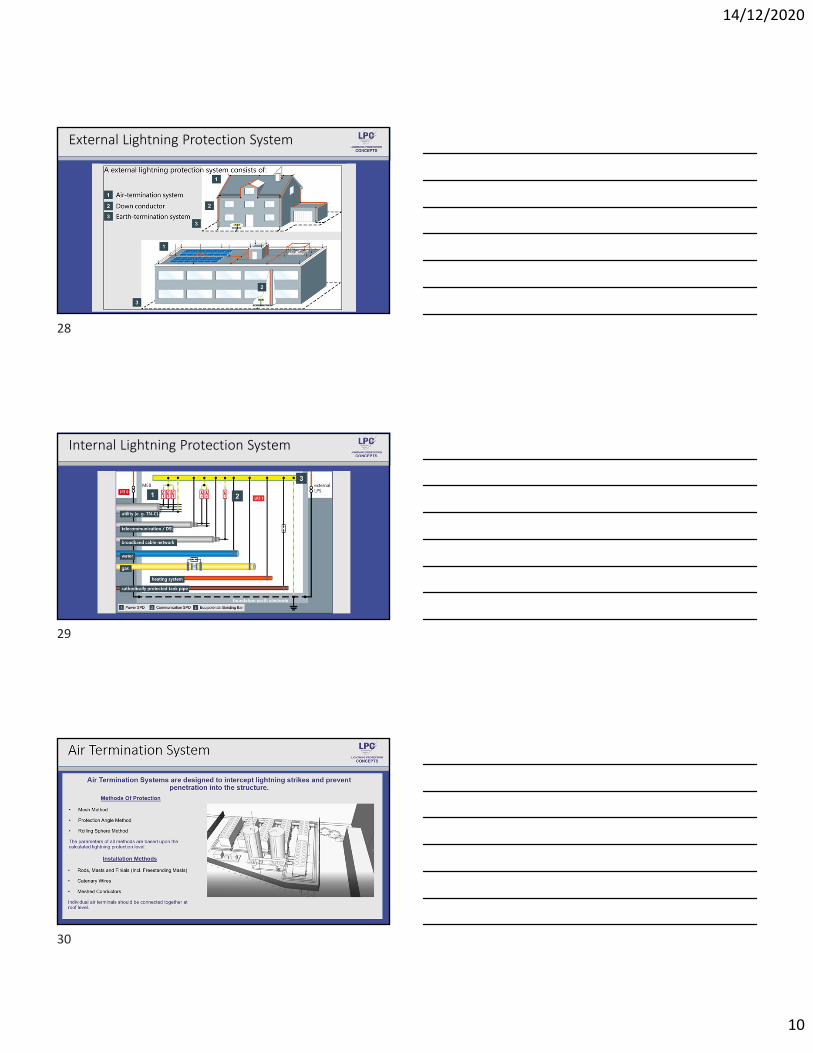
What it an effective & safe LPS?
External lightning protection systems• ATS, DCS & ETS
Internal lightning protection systems• LEB, SPD, Routing & Shielding
What is an Effective & Safe LPS?
Designing effective & safe lightning protection systems (LPS)
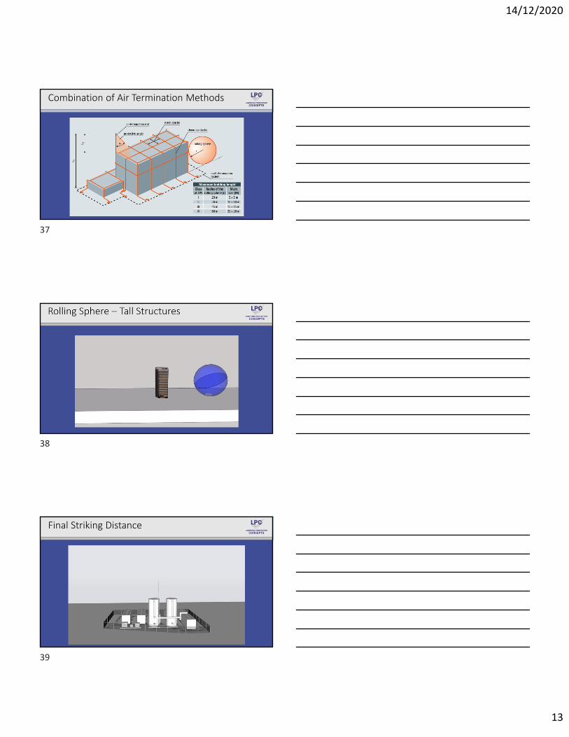
Total Lightning Protection System
25
26
27
14/12/2020
10
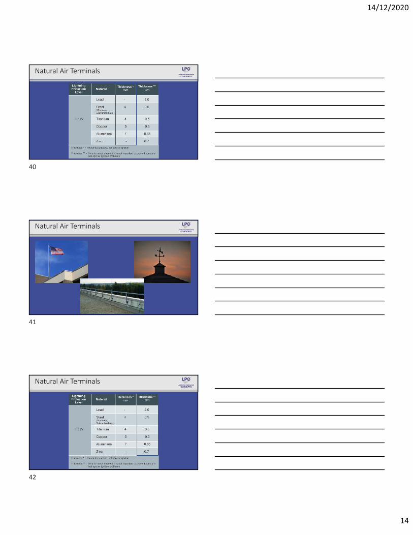
External Lightning Protection System
Internal Lightning Protection System
28
29
30

14/12/2020
11
Rolling Sphere Method
The rolling sphere method is the universal method of design and is recommended for geometrically complicated applications.
31
32
33

14/12/2020
12
Rolling Sphere Method
Rolling Sphere Method – 3D Modeling
34
35
36
14/12/2020
13
Combination of Air Termination Methods
Final Striking Distance
37
38
39
14/12/2020
14
Natural Air Terminals
Natural Air Terminals
Natural Air Terminals
40
41
42
14/12/2020
15
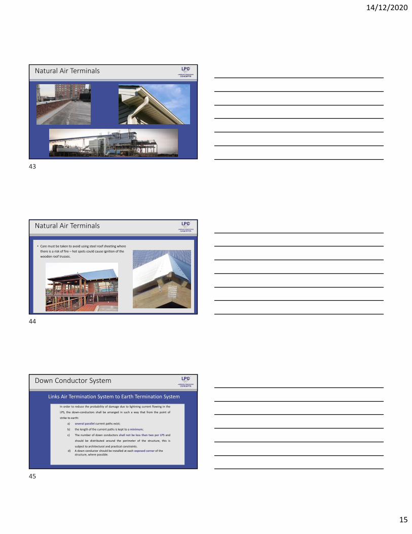
Natural Air Terminals
Natural Air Terminals
• Care must be taken to avoid using steel roof sheeting where
there is a risk of fire – hot spots could cause ignition of the
wooden roof trusses.
Down Conductor System
Links Air Termination System to Earth Termination System
In order to reduce the probability of damage due to lightning current flowing in the
LPS, the down‐conductors shall be arranged in such a way that from the point of
strike to earth:
a) several parallel current paths exist;
b) the length of the current paths is kept to aminimum;
c) The number of down conductors shall not be less than two per LPS and
should be distributed around the perimeter of the structure, this is
subject to architectural and practical constraints.
d) A down conductor should be installed at each exposed corner of the structure, where possible.
43
44
45

14/12/2020
16
Down Conductor System
Down Conductor Spacing
Maximum Spacing of Down Conductors Depends on Lightning Protection Level
Down Conductors Dimensions
• Copper, aluminium and galvanized steel are generally used as down conductor materials, the minimum dimension as shown below:
• When the separation distance from a down conductor to a conductive element cannot be assured, the use of HVI conductors should be considered.
46
47
48

14/12/2020
17
Types of Down Conductors
Type 1: External Down Conductors Type 2: Natural Down Conductors• Purpose built down conductors installed on
the outside of the structure.
• Copper, aluminium and galvanized steel are generally used as external down conductors.
External down conductors are subject to the maintenance of separation distances
• Natural elements such as structural steelwork, concrete steel reinforcing, metallic facades and welded rainwater downpipes should be utilized as natural down conductors.
Care must be taken to ensure electrical continuity across all‐natural down conductors.
Natural Down Conductors
Natural Down Conductors
49
50
51

14/12/2020
18
Earth Termination System
Safe Dissipation of Lightning Current
General
The shape and dimension of the lightning protection earthing system are important when dealing with safe dispersion of the lightning current into the ground.
In order to minimize any dangerous overvoltage's a low resistance earthing system is recommended –if possible lower than 10 Ohms.
A single integrated earthing system is preferable, which is suitable for all purposes (i.e. lightning protection, power systems, telecommunications systems and data systems).
Alternatively all earthing systems shall be equipotentially bonded together.
52
53
54

14/12/2020
19
Soil Resistivity Measurement
Soil Resistivity Measurement
55
56
57

14/12/2020
20
Types of Earth Termination Systems
Selection of Type of Earth Electrode
Type A: Individual Earth Electrodes• Recommended for:
‐ Lightning protection level III and IV systems‐ Structures with low soil resistivity values‐ Retrofits where Type B electrodes are unpractical.
Type B: Ring Earth Electrodes• Recommended for:
‐ Lightning protection level I and II systems‐ Integrated earthing systems‐ Bare solid rock sites (only Type B)‐ Structures with extensive electronics‐ Structures with a high risk of fire
58
59
60

14/12/2020
21
Earth Electrode Dimensions
61
62
63

14/12/2020
22
Lightning Equipotential Bonding
Prevents Dangerous Sparking Inside The Structure
Equipotentialization is performed to prevent dangerous sparking within a structure due to lightning current flowing in the external
LPS or any conductive parts of a structure.
The equipotential bonding of the following elements to the external LPS is essential :
• Metal Installations• Power Supply Systems• Information Technology Systems
Types of Equipotential Bonding:
• Bonding via bonding conductors• Bonding via surge protection devices
Lightning Equipotential Bonding
64
65
66

14/12/2020
23
67
68
69

14/12/2020
24
Separation Distance Principles
Separation Distances Prevent Uncontrolled Flashovers“An isolated external LPS should be used when the flow of the lightning current into bonded internal
conductive parts may cause damage to the structure or its contents.” – IEC 62305 Part 3
The uncontrolled entry of partial lightning currents into a structure
inadequate separation distances can lead to flashovers between the LPS and internal conductive elements of the
structure.
This can result in the risk of fire and damage to internal systems
The correct separation distance therefore must be maintained to prevent these
flashovers.
distance between two conductive parts at which no dangerous sparking can occur
=
70
71
72

14/12/2020
25
Isolated vs Non‐Isolated LPS
73
74
75

14/12/2020
26
Separation Distance Exceptions
Separation Distances Can Be Ignored If :
• Interconnected concrete reinforcing is utilised as natural down conductors – applies only to down conductors.
• Interconnected structural steel work is utilised as natural down conductors – applies only to down conductors.
• HVI (High Voltage Insulation) Conductors are utilised for Air Termination and Down Conductor Systems.
76
77
78

14/12/2020
27
Separation Distance Simulations
Separation Distance Simulations
79
80
81

14/12/2020
28
LPS for Rooftop PV Systems
Isolated LPS for Rooftop PV Systems
Isolated LPS for Rooftop PV Systems
82
83
84

14/12/2020
29
Non‐Isolated LPS for Rooftop PV Systems
Non‐Isolated LPS for Rooftop PV Systems
Scenario 1 – Structures without LPS
• Surge protection to PV system by means of Class 2 & 3 surge arresters• Equipotential bonding to electrical earthing system by means of 16mm² copper conductors.
85
86
87

14/12/2020
30
Scenario 2 – Structures with Isolated LPS
• Surge protection to PV system by means of Class 2 & 3 SPDs – Class 1 SPD in Main DB• Equipotential bonding to electrical earthing system by means of 16mm² copper conductors.
Equipotential Bonding
The bonding of the PV panels is carried out at the internal earth bar only.
No Bonding to the LPS is carried out for isolated LPS.
Isolated LPS
An isolated LPS is achieved when the calculated separation distance between the
LPS and the PV system is maintained.
Scenario 2 – Structures with Isolated LPS
Scenario 3 – Structures with Non‐isolated LPS
• Surge protection to PV system by means of Class 1 & 2 SPDs – Class 1 SPD in Main DB• Equipotential bonding to electrical earthing system by means of 16mm² copper conductors.
88
89
90

14/12/2020
31
Scenario 3 – Structures with Non‐isolated LPS
Equipotential BondingPV panels are bonded directly to the LPS and
the internal earth bar
Air termination rods and finials are mounted to PV
framework
SANS Update – Pending Changes
SANS 10313 Update
Addressing applications which SANS 62305 does not cover are:
Thatch, Solar Rooftop, Recreational facilities, Safe shelters and Mining applications
Update of the lightning ground flash data
Adoption of new innovations and technologies
Mandating the use of LPS Installation Safety Report – accountability and transparency
SANS Update – Pending Changes
SANS 10142‐1‐2 / SANS 10313
• EGI Categories A1 and A2 are exempt from installing any external lightning protection systems. SANS 10313 recommends a minimum LPL III for Categories A2 and A3.
• A risk assessment, according to SANS 10313, shall be performed for EGI Category A3 (as per Section 4.5.1, Generator Categories by Capacity). If the risk profile shows a high risk, a full lightning protection system must be installed for the EGI.
91
92
93

14/12/2020
32
SANS Update – Lightning Ground Flash Index
SANS Update – Pending Changes
SANS 10142‐1
External LPS must be bonded to the main
consumer earth‐terminal
When external lightning protection
systems are fitted a Type 1 SPD shall be
fitted in conjunction with a Type 2 SPD
SANS Update – Pending Changes
SANS 10142‐1
Simple risk assessment to
determine the need for a surge
protective device (SPD)
How to select & wire the SPDs
correctly?
New SPD test report to be issued
as part of the supplementary COC
94
95
96
14/12/2020
33
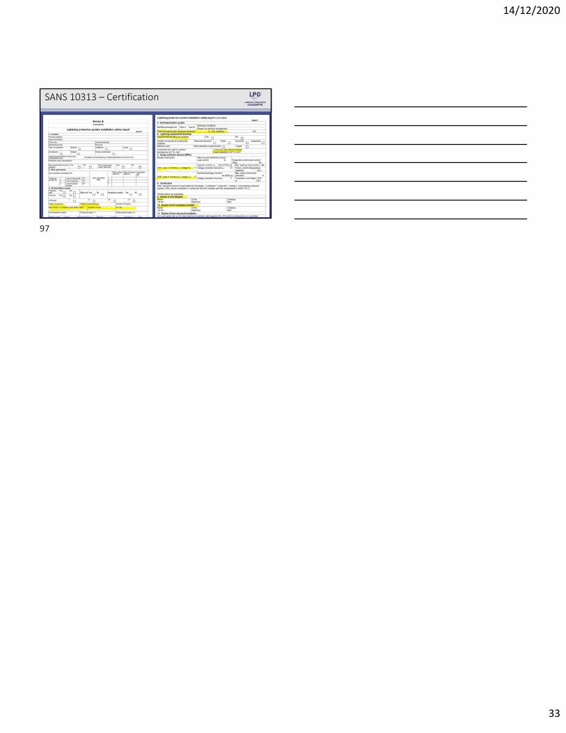
SANS 10313 – Certification
97