Low noise, vibration and harshness solutions for in-line ...
21
1 Low noise, vibration and harshness solutions for in-line three-cylinder range-extender and hybrid electric vehicles Peter R Hooper Department of Mechanical Engineering, Auckland University of Technology, St Paul Street, Auckland, 1010, New Zealand Corresponding author: Tel: +64 (0)9 921 9999; Fax: +64 (0)9 921 9973 E-mail address: [email protected] Abstract: Consideration of internal combustion engine formats suitable for Hybrid or Range- extender Electric Vehicles usually focuses on selecting a power plant, which is as compact as possible to meet the demands and constraints of the installation. In-line three-cylinder engines often provide an attractive solution for such vehicles. This paper presents a low emission two-stroke engine of in-line three-cylinder format and draws a comparison with an equivalent four-stroke engine. The particular focus of the analysis is on strategies for minimization of noise, vibration and harshness (NVH) with significant reduction in piston lateral force compared with the four-stroke unit. The design also considers a balance shaft arrangement to further assist with NVH reduction. The presented arrangement demonstrates an integrated induction control/balance shaft arrangement which erodes the usual cost penalties typical of balance shaft consideration in three-cylinder engines. Keywords: Hybrid Electric Vehicle, Range Extender Electric Vehicle, stepped piston engine, two- stroke cycle engine, four-stroke cycle engine, Noise Vibration and Harshness, engine modelling/simulation, three-cylinder engine, balance shaft.
Transcript of Low noise, vibration and harshness solutions for in-line ...

1
Low noise, vibration and harshness solutions for in-line three-cylinder range-extender and hybrid electric vehicles Peter R Hooper Department of Mechanical Engineering, Auckland University of Technology, St Paul Street, Auckland, 1010, New Zealand Corresponding author: Tel: +64 (0)9 921 9999; Fax: +64 (0)9 921 9973 E-mail address: [email protected] Abstract: Consideration of internal combustion engine formats suitable for Hybrid or Range-extender Electric Vehicles usually focuses on selecting a power plant, which is as compact as possible to meet the demands and constraints of the installation. In-line three-cylinder engines often provide an attractive solution for such vehicles. This paper presents a low emission two-stroke engine of in-line three-cylinder format and draws a comparison with an equivalent four-stroke engine. The particular focus of the analysis is on strategies for minimization of noise, vibration and harshness (NVH) with significant reduction in piston lateral force compared with the four-stroke unit. The design also considers a balance shaft arrangement to further assist with NVH reduction. The presented arrangement demonstrates an integrated induction control/balance shaft arrangement which erodes the usual cost penalties typical of balance shaft consideration in three-cylinder engines. Keywords: Hybrid Electric Vehicle, Range Extender Electric Vehicle, stepped piston engine, two-stroke cycle engine, four-stroke cycle engine, Noise Vibration and Harshness, engine modelling/simulation, three-cylinder engine, balance shaft.

2
INTRODUCTION The application of in-line three-cylinder engines in automotive power train systems has increased significantly during recent small passenger car development. This has seen the displacement of the predominant in-line four-cylinder internal combustion engine power plant in several cases. Whilst a key drive within the industry to develop propulsion systems employing solely electrical propulsion systems is evident the fact remains that range anxiety for pure EVs is a significant problem for customers unless the vehicle can be used only for inner city transportation. A solution to the range issues can be met with hybrid electric (HEV) and/or range-extender electric vehicles (RE-EV) as demonstrated by the work of Mackintosh et al [1]. The power train duplication however equally presents challenges. Whilst the slow charge rate, battery deterioration and range problems may be possible to overcome, there is a cost addition to the vehicle albeit offset to an extent by the reduced battery cost evident within comparable HEVs or RE-EVs against equivalent all electric vehicles. To counter the cost addition further, any significant IC engine cost reduction will help offset the penalty, and to this end, smaller engines with reduced numbers of cylinders have been considered. In addition to this the unique new challenges created by low speed high load IC engine operation, to meet the demands for periodic onboard battery charging in HEVs/RE-EVs, presents significant low frequency booming noise problems as discussed by Joslin et al [2]. Even without considering HEV or RE-EV applications, the increased introduction of down-sized engines with low numbers of cylinders in conventional power train application presents NVH issues particularly at low frequencies as discussed by Brandl et al [3]. Compared with an equivalent in-line four-cylinder unit the in-line three-cylinder engine presents cost benefits but greater effort is required to counter the appreciable increased noise, vibration and harshness (NVH) challenges. Naturally the fundamental excitation frequency is changed for the same given maximum power operating speed. However, in addition to this, due to the 120° phasing of the crank pin positions, the journals are in different planes. This leads to an inherent couple acting along the axis of the crankshaft. The effects can be counter acted to limited effect via engine mount optimization as demonstrated by the research of Kim et al [4], Shital et al [5] and Sachdeva [6]. Alternatively, the couple can be successfully counter acted by more direct methods via the addition of a contra-rotating balance shaft designed to cancel the action of the couple. This has been considered via the research of Kim et al [4], Acri et al [7], Coltman et al [8], Suh et al [9], and Heifetz et al [10]. Most research has been performed in this area with balance shaft application with four-stroke in-line three-cylinder units as the subject engine [6-10]. Two-stroke cycle engines for range extenders or hybrid drive train have been researched by Stan and Personnaz [11], Mattarelli et al [12], Borgi et al [13] and Hooper [14][15]. Some researchers have considered the in-line three-cylinder two-stroke cycle engine as a suitable candidate as demonstrated by the work of Duret et al [16], Schlunke [17], Cantore and Mattarelli [18], Mattarelli [19] and Mattarelli and Rinaldini [20], but none of these examples applied a balance shaft. A key challenge to the technology can be found in the commonly perceived emission concerns associated with the two-stroke engine. However; Duret [16], Schlunke [17] and Shawcross et al [21] and more recently the work of Turner et al [22] have demonstrated exceptionally low emission levels with NOx being difficult to measure [22] meaning that the engine type could present potential to offer improved NVH together with significant NOx emission reduction. The added benefit of reduced production cost of the two-stroke engine compared with an equivalent four-stroke engine allows a reduction in unit cost countering the additional cost add-on presented by the dual power train requirement. The cost reduction can also offset the added cost of the balance shaft system.
3
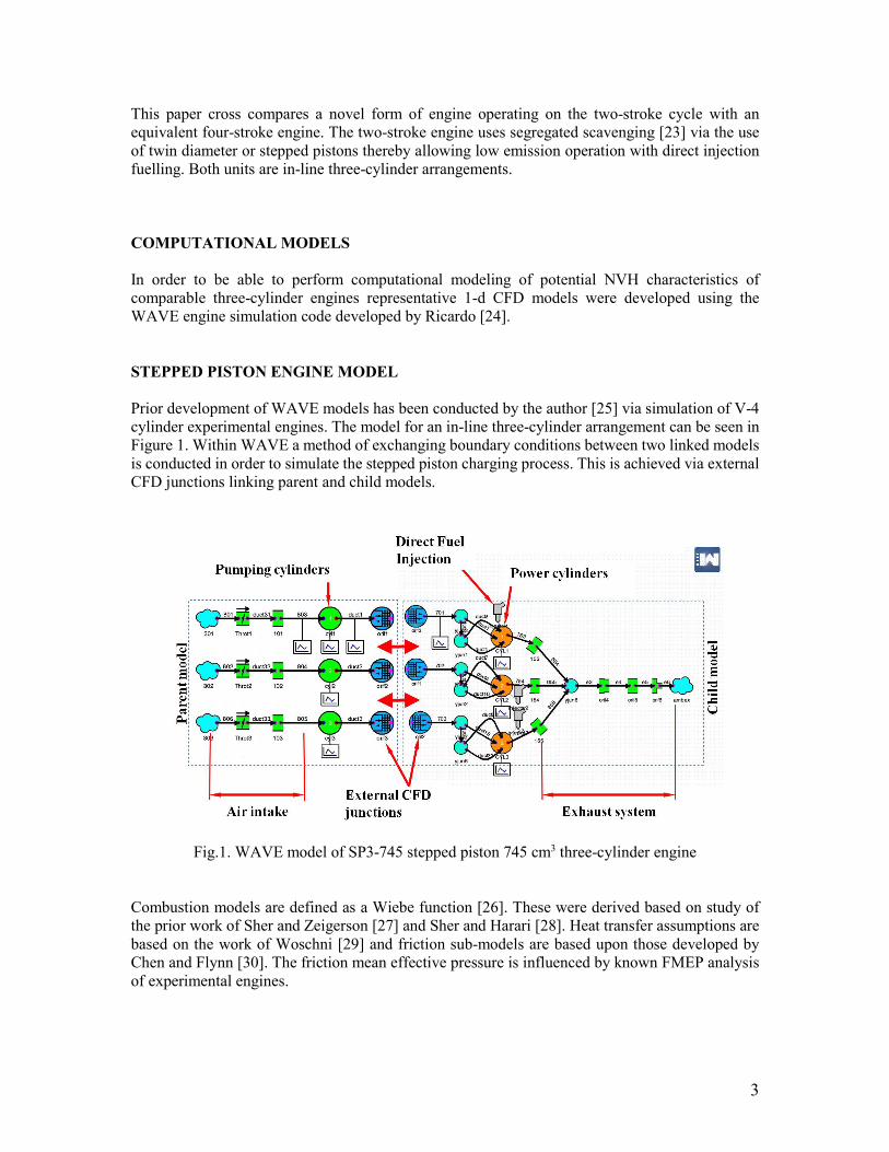
This paper cross compares a novel form of engine operating on the two-stroke cycle with an equivalent four-stroke engine. The two-stroke engine uses segregated scavenging [23] via the use of twin diameter or stepped pistons thereby allowing low emission operation with direct injection fuelling. Both units are in-line three-cylinder arrangements. COMPUTATIONAL MODELS In order to be able to perform computational modeling of potential NVH characteristics of comparable three-cylinder engines representative 1-d CFD models were developed using the WAVE engine simulation code developed by Ricardo [24]. STEPPED PISTON ENGINE MODEL Prior development of WAVE models has been conducted by the author [25] via simulation of V-4 cylinder experimental engines. The model for an in-line three-cylinder arrangement can be seen in Figure 1. Within WAVE a method of exchanging boundary conditions between two linked models is conducted in order to simulate the stepped piston charging process. This is achieved via external CFD junctions linking parent and child models.
Fig.1. WAVE model of SP3-745 stepped piston 745 cm3 three-cylinder engine Combustion models are defined as a Wiebe function [26]. These were derived based on study of the prior work of Sher and Zeigerson [27] and Sher and Harari [28]. Heat transfer assumptions are based on the work of Woschni [29] and friction sub-models are based upon those developed by Chen and Flynn [30]. The friction mean effective pressure is influenced by known FMEP analysis of experimental engines.

4
FOUR-STROKE ENGINE MODEL To provide data for a suitable equivalent four-stroke engine a model was developed within the architecture of WAVE. The model outline can be seen in Figure 2.
Fig.2. WAVE model of 4s-1L four-stroke 1006 cm3 three-cylinder engine As for the stepped piston engine models Wiebe functions are used to define the combustion models the parameters were set using data developed by Ricardo as were the assumptions for friction and heat transfer. The fundamental input data for the two computational models can be seen in Table 1
Table.1. Reference data for engine comparisons
Engine
SP3-745 Stepped piston
4s-1L
Four-stroke
Cycle
2
4
Cylinders
3 in-line
3 in-line
Consecutive firing intervals (°)
120
240
Swept volume (cm³)
745
1006
Cylinder bore diameter (mm)
74.5
74
Stroke (mm)
57
78
Reciprocating mass (kg)
0.678
0.518
Centre distance between cylinders (mm)
112
104

5
ENGINE NOISE VIBRATION AND HARSHNESS The fundamental variables that influence the axial forces within an internal combustion engine are a function of the geometry of the engine stroke, connecting rod centre distance, reciprocating mass and rotational speed as defined for first and second orders by the approximate expression in equation (1): -
+≈ θθω 2coscos2
lrrm F recr (1)
Equation (1) is an approximation due the fact that the geometry of engines is such that the ratio of crank throw to connecting rod centre distance (r/l) is so small that higher orders in excess of (r/l)4 and above can be ignored. Care does need to be applied however when the higher orders coincide and therefore add giving an appreciable magnitude that can be significant in torsional vibration terms. The dimensional aspects of the variables in equation (1) are defined for clarity in Figure 3.
Fig.3. Slider crank geometry and definition of variables The models developed within WAVE provide computations of the cylinder pressures of the fundamental engine types under consideration within this study. The data output is then exported from the WAVE model environment and used further to determine the gas forces acting on the piston crown based upon the engine geometry highlighted in Figure 3. From this analysis the corresponding connecting rod forces and lateral forces acting on the piston towards the cylinder bore can then be determined.

6
IN-LINE THREE-CYLINDER ENGINES The typical crankshaft arrangement for in-line three-cylinder engines of either two or four-stroke configuration is shown in Figure 4. The crank pins are arranged at positions spaced at 120° intervals.
Fig.4. General arrangement of crankshaft for in-line three-cylinder engine
If the distance between centres of consecutive cylinders is defined by LCD then it can be seen that due to the position of crank pins 2 and 3 being in different planes to that of the reference crank pin of cylinder 1 then a pitching couple acting along the engine crankshaft axis will be evident as a function of LCD and the magnitude of forces from cylinders 2 and 3. The magnitude of the first order couple can be determined from the expression shown in equation (2): -
( )322 cos2cos θθω CDCDrecI LLrmC += (2)
Simplifying equation (2) to standardize on the more convenient reference of cylinder 1 we arrive at: -
( ) ( )( )°++°+= 240cos2120cos 112 θθω CDCDrecI LLrmC (3)
If we consider the second order force terms from equation (1) by a similar assessment of the couple we can determine the second order couple from: -
( ) ( )[ ]°++°+
= 4802cos22402cos 11
2 θθω CDCDrecII LLlrrmC (4)
7
A vector analysis of the couples can be performed in terms of the couple orders and relevant frequencies. The analysis will determine resultant couples as follows for first order in equation (5) and for second order in equation (6): -
( )°+= 210cos3 12 θω CDrecII LrmC (5)
( )°+
= 1502cos3 1
2 θω CDrecII LlrrmC (6)
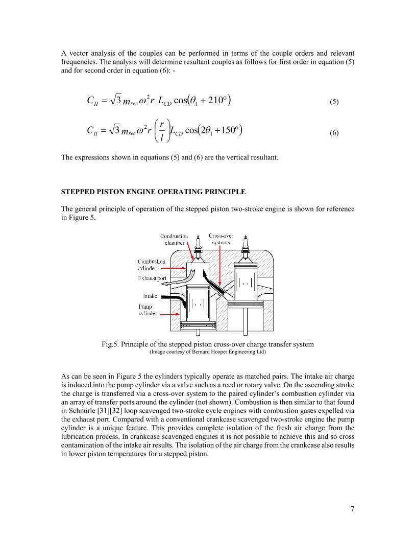
The expressions shown in equations (5) and (6) are the vertical resultant. STEPPED PISTON ENGINE OPERATING PRINCIPLE The general principle of operation of the stepped piston two-stroke engine is shown for reference in Figure 5.
Fig.5. Principle of the stepped piston cross-over charge transfer system
(Image courtesy of Bernard Hooper Engineering Ltd) As can be seen in Figure 5 the cylinders typically operate as matched pairs. The intake air charge is induced into the pump cylinder via a valve such as a reed or rotary valve. On the ascending stroke the charge is transferred via a cross-over system to the paired cylinder’s combustion cylinder via an array of transfer ports around the cylinder (not shown). Combustion is then similar to that found in Schnürle [31][32] loop scavenged two-stroke cycle engines with combustion gases expelled via the exhaust port. Compared with a conventional crankcase scavenged two-stroke engine the pump cylinder is a unique feature. This provides complete isolation of the fresh air charge from the lubrication process. In crankcase scavenged engines it is not possible to achieve this and so cross contamination of the intake air results. The isolation of the air charge from the crankcase also results in lower piston temperatures for a stepped piston.
8
STEPPED PISTON THREE-CYLINDER ENGINE
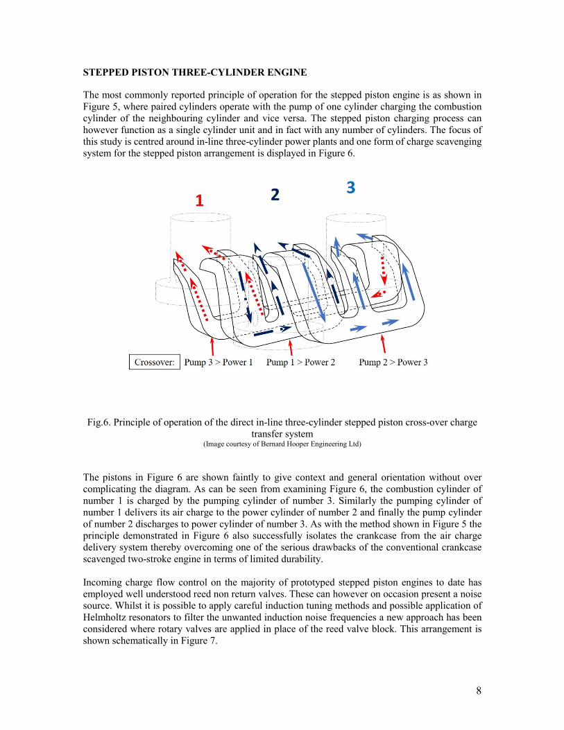
The most commonly reported principle of operation for the stepped piston engine is as shown in Figure 5, where paired cylinders operate with the pump of one cylinder charging the combustion cylinder of the neighbouring cylinder and vice versa. The stepped piston charging process can however function as a single cylinder unit and in fact with any number of cylinders. The focus of this study is centred around in-line three-cylinder power plants and one form of charge scavenging system for the stepped piston arrangement is displayed in Figure 6.
Fig.6. Principle of operation of the direct in-line three-cylinder stepped piston cross-over charge transfer system
(Image courtesy of Bernard Hooper Engineering Ltd) The pistons in Figure 6 are shown faintly to give context and general orientation without over complicating the diagram. As can be seen from examining Figure 6, the combustion cylinder of number 1 is charged by the pumping cylinder of number 3. Similarly the pumping cylinder of number 1 delivers its air charge to the power cylinder of number 2 and finally the pump cylinder of number 2 discharges to power cylinder of number 3. As with the method shown in Figure 5 the principle demonstrated in Figure 6 also successfully isolates the crankcase from the air charge delivery system thereby overcoming one of the serious drawbacks of the conventional crankcase scavenged two-stroke engine in terms of limited durability. Incoming charge flow control on the majority of prototyped stepped piston engines to date has employed well understood reed non return valves. These can however on occasion present a noise source. Whilst it is possible to apply careful induction tuning methods and possible application of Helmholtz resonators to filter the unwanted induction noise frequencies a new approach has been considered where rotary valves are applied in place of the reed valve block. This arrangement is shown schematically in Figure 7.

9
Fig.7. In-line three-cylinder stepped piston engine general arrangement with integrated balance shaft/rotary valve induction system
(Image courtesy of Bernard Hooper Engineering Ltd) A relatively low cost addition can be readily applied to the charging methodology shown in Figure 7. If the shaft carrying the rotary valves is further extended to carry counter balance weights then an integrated contra-rotating balance shaft/rotary valve system can be exploited. The troublesome rocking couple of the three-cylinder engine arrangement can therefore be countered by effective design of suitable masses. If cylinder number 2 is assumed to be at the centre of the engine with symmetry about this position for the remaining cylinders, crankshaft and balance shaft, the required mass, m2, for the counter weights can be calculated from the following equation.
=
CD
CD
BL
rrmm2
112 2 (7)
RESULTS FROM COMPUTATIONAL MODELS Data from the WAVE models is compared in Figure 8 for both the 4s-1L four-stroke engine and SP3-745 stepped piston engine.

10
Fig.8. WAVE model output for 4s-1L four-stroke engine and SP3-745 stepped piston engines at
6000 rpm Both engines compared in Figure 8 are designed to produce maximum power at 6000 rpm. The x-axis of Figure 8 extends over 720° in order to complete the four-stroke cycle with one pulse from each of the three sequentially firing cylinders. The stepped piston engine has completed twice the number of firing pulses due to operation on the two-stroke cycle. Data from the model runs has been used to quantify the forces acting within the two fundamental engine types. The first and second order forces are shown for both engines in Figures 9 and 10.
11
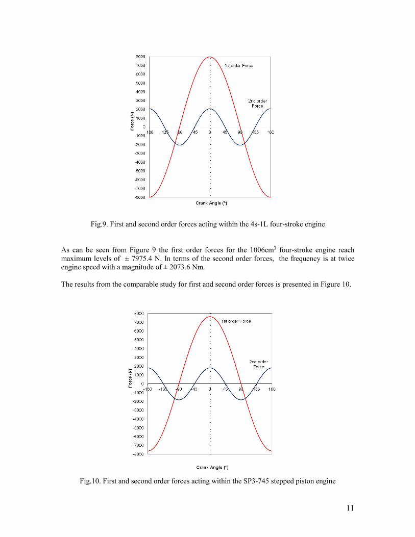
Fig.9. First and second order forces acting within the 4s-1L four-stroke engine
As can be seen from Figure 9 the first order forces for the 1006cm3 four-stroke engine reach maximum levels of ± 7975.4 N. In terms of the second order forces, the frequency is at twice engine speed with a magnitude of ± 2073.6 Nm. The results from the comparable study for first and second order forces is presented in Figure 10.
Fig.10. First and second order forces acting within the SP3-745 stepped piston engine

12
The 745cm3 three-cylinder stepped piston engine can be seen to generate maximum first and second order forces of ± 7628.4 N and ± 1811.7 N respectively. A comparison of magnitudes of first and second order couples for both engines can be seen in Figure 11 and Figure 12 for the four-stroke 4s-1L and the stepped piston in-line three-cylinder engines respectively.
Fig.11. First and second order couples - 4s-1L four-stroke engine
For the 1006 cm3 four-stroke engine the magnitude of the first order couple can be observed to reach maximum values of ± 1436.6 Nm. The maximum levels to be expected at second order are at twice engine speed and fluctuate between maximum values of ± 373.5 Nm. Performing a comparative analysis in terms of first and second order couples in Figure 12 a higher maximum first order couple of ± 1479.8 Nm can be seen.

13
Fig.12. First and second order couples - SP3-745 stepped piston engine
In terms of second order couple the maximum predicted values are ± 351.5 Nm. The prediction of forces previously conducted is further revisited in Figures 13 and 14 to determine the forces transmitted to the connecting rod and laterally from the piston towards the cylinder bore. The lateral piston forces are significant in terms of piston – cylinder wall impact and are therefore instrumental in management of NVH by minimising their magnitudes.
Fig.13. Comparison of connecting rod forces for 4s-1L four-stroke and SP3-745 stepped piston engines at 6000 rpm

14
The stepped piston engine maximum connecting rod force shown in Figure 13 is 14945 N and occurs at 12.5° ATDC. By comparison the same maximum force occuring in the four-stroke 4s-1L engine is of the order of 26792 N.
Fig.14. Comparison of piston lateral forces for 4s-1L four-stroke and SP3-745 stepped piston engines at 6000 rpm
In terms of maximum side forces; the four-stroke 4s-1L engines can be seen to exert 2768 N occuring at 31° ATDC. The stepped piston engine exerts a significantly lower magintude lateral force of 1170 N. Piston mass in a four-stroke cycle engine is more critical than it is for two-stroke engines for the same comparable maximum engine speed. However reducing piston mass would reduce the magnitude of the rocking couple evident with in-line three-cylinder engines. As a further element to the study presented in this paper, a reduced reciprocating mass analysis has been considered for the SP3-745 engine. Considering the pump section of the stepped piston, the stress in this area is very low. Thermally the loading is significantly lower than in the combustion section and the pressure exerted on the pumping flange is low. The majority of pistons designed for prototype stepped piston engines to date have historically been produced following conventional piston design processes and specifying normal aluminium castings with high silicon alloy. So far a zero ovality requirement has been found to achieve excellent results. It is possible to reduce the reciprocating mass of a stepped piston further by constructing the piston in two sections using magnesium alloy for the pumping section. This could be welded to the combustion piston section via electron beam methods prior to final machining. Studies have so far indicated that a composite piston approach could reduce the SP3-745 piston mass from 518 g to 471 g. This value includes
15
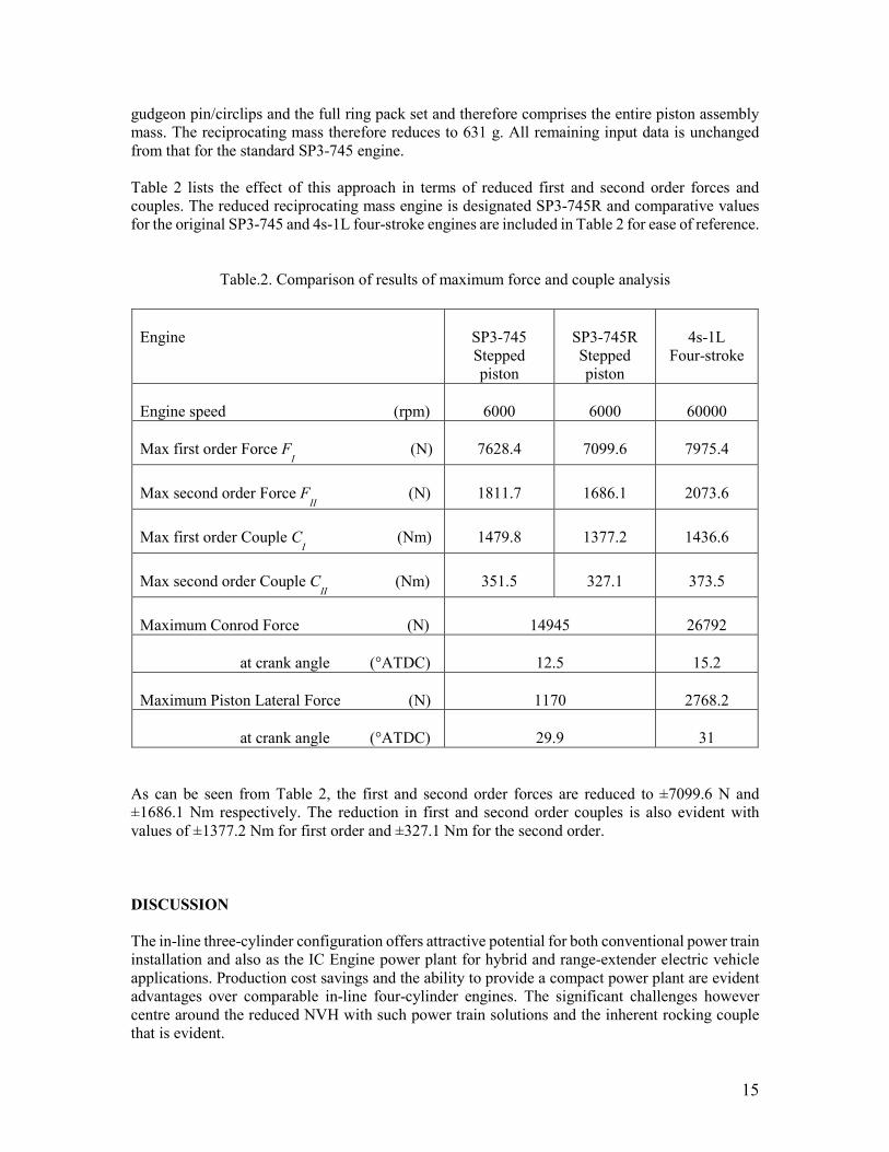
gudgeon pin/circlips and the full ring pack set and therefore comprises the entire piston assembly mass. The reciprocating mass therefore reduces to 631 g. All remaining input data is unchanged from that for the standard SP3-745 engine. Table 2 lists the effect of this approach in terms of reduced first and second order forces and couples. The reduced reciprocating mass engine is designated SP3-745R and comparative values for the original SP3-745 and 4s-1L four-stroke engines are included in Table 2 for ease of reference.
Table.2. Comparison of results of maximum force and couple analysis
Engine
SP3-745 Stepped piston
SP3-745R Stepped piston
4s-1L
Four-stroke
Engine speed (rpm)
6000
6000
60000
Max first order Force F
I (N)
7628.4
7099.6
7975.4
Max second order Force F
II (N)
1811.7
1686.1
2073.6
Max first order Couple C
I (Nm)
1479.8
1377.2
1436.6
Max second order Couple C
II (Nm)
351.5
327.1
373.5
Maximum Conrod Force (N)
14945
26792
at crank angle (°ATDC)
12.5
15.2
Maximum Piston Lateral Force (N)
1170
2768.2
at crank angle (°ATDC)
29.9
31
As can be seen from Table 2, the first and second order forces are reduced to ±7099.6 N and ±1686.1 Nm respectively. The reduction in first and second order couples is also evident with values of ±1377.2 Nm for first order and ±327.1 Nm for the second order. DISCUSSION The in-line three-cylinder configuration offers attractive potential for both conventional power train installation and also as the IC Engine power plant for hybrid and range-extender electric vehicle applications. Production cost savings and the ability to provide a compact power plant are evident advantages over comparable in-line four-cylinder engines. The significant challenges however centre around the reduced NVH with such power train solutions and the inherent rocking couple that is evident.

16
Engine technology presented in this paper has the potential to counter the magnitude of the rocking couple and with integration of a low cost addition balance shaft arrangement can counter the couple to offer further refinement. Many two-stroke engines use reed valves as a means of intake air flow management. The reed valve is essentially a petal type non-return valve preventing reverse air flow during induction of the fresh air charge. The reed valve has been cited as a noise source in conventional crankcase scavenged engines [21] which can have a negative effect on engine NVH at certain resonant frequencies. These can be managed to some extent by intake tract geometry and variations of the reed petal characteristics as discussed by Hooper and Al-Shemmeri [33] and Cunningham et al [34]. One possible method of countering noise emission problems from the reed valve as a source could be possible by adopting the integrated rotary valve intake control as part of the balance shaft as suggested. It should be pointed out that it is possible avoid use of a balance shaft with an in-line three-cylinder arrangement by application of additional mass outside the engine crankshaft. This has been demonstrated by the Ford 1.0 litre Eco-boost engine as presented by Ernst et al [35] and Abe and Felice [36]. However; the application of masses to the engine flywheel and front auxiliary drive pulley does not completely counter the primary couple. By careful orientation of the masses it is possible to convert much of the motion into a lateral plane rather than the vertical or cylinder acting plane. The lateral plane engine motion can then be effectively absorbed by suitable selection of engine anti-vibration mountings thereby avoiding the need for a balance shaft. Even without the installation of the counter balance shaft the study has shown significant reductions in the magnitude of the first and second order rocking couples when compared to an equivalent in-line three-cylinder engine of conventional four-stroke form. Whilst the first order couple is predicted to be 3% higher for the stepped piston engine the second order couple shows a 5.9% reduction. Further reduction has been modelled where a strategy of reciprocating mass limitation is adopted via composite construction of the piston using a magnesium pumping piston. In terms of first and second order forces a 6.9% reduction is observed against the baseline SP3-745 standard piston engine. Considering the resultant first order couple by this methodology a reduction of 4.1% is indicated against the base-line four-stroke bench mark and in terms of second order couple a 12.4% reduction is apparent from the models. Modelling of forces within the subject engines considered, based upon predicted cylinder pressure, has indicated a reduction in piston lateral force of the order of almost 58% with the stepped piston engine design. BMEP for the same equivalent output is of course half the magnitude of the four-stroke engine when a two-stroke is employed. Peak cylinder pressures are also lower for two-stroke engines at the same comparable operating condition. This therefore has a significant impact on the piston lateral and connecting rod forces. The frequency of occurrence of the forces is naturally twice that of the four-stroke engine. The magnitude of the forces are significant in assessing the likelihood of piston-bore impact which is a major area of focus for NVH engineers when trying to reduce engine mechanical noise from the piston as a source excitation. The stepped piston also offers an alternative bore guidance methodology that significantly differs to that of both conventional two and four-stroke engine methods as discussed by Hooper [37] with further modeling of this aspect ongoing. The noise output from experimental prototype units using stepped piston technology has often yielded low magnitude levels and further exploration of this is planned for future research work. Conventional crankcase scavenged two-stroke engines are predominantly designed with rolling element bearings throughout the crankshaft assembly and often in the connecting rod small end area too. Roller bearings are also a potential source for noise emission particularly when compared

17
with plain bearings that are common design practice in four-stroke engines. An advantage offered by segregated scavenging two-stroke engines is that they allow the application of plain shell bearings within the crankshaft design. The stepped piston form of segregated scavenging allows this bearing design to be exploited thereby presenting further noise reduction when compared with conventional two-stroke units. It also eliminates the valve train source noise that would be evident with other externally scavenged two-stroke engines employing poppet valves as indeed. The isolated crankcase and ability to provide a re-circulatory lubrication system akin to four-stroke engine methodologies also allows a key durability factor to be secured that cannot be achieved with crankcase scavenging. Using crankcase scavenging oil entering the crankcase has to be metered to very low levels. Good results have been achieved as indicated by Shawcross et al [21] but it is a diminishing return. Lower emissions ultimately require lower oil supply. This restriction does not apply with stepped piston charging. Furthermore the additional oil supply facility provides beneficial cooling to the piston which can be a problem in conventional engines. The very low NOx emission of two-stroke engines as discussed by Blundell et al [38] and Turner et al [22] has been observed with stepped piston engines [14][23] but the implementation of variable compression ratio technology as discussed by Turner et al [22] could further reduce NOx emission and offer even greater CO2 reductions. HEVs and RE-EVs already readily demonstrate fuel efficiency improvements and therefore reduced CO2 emissions but application of VCR gives further potential reduction beyond the immediately apparent benefits whilst also addressing the range anxiety issues of fully electric vehicles. CONCLUSIONS
An alternative approach to in-line three-cylinder power plant design for HEVs, RE-EVs and conventional power train solutions has been presented with a focus on aspects of the stepped piston engine that could offer technological advantage over conventional engine forms. The ability to reduce NVH characteristics usually comes with a significant cost addition; however the technology discussed has the potential to reduce unit cost. Modelled piston lateral forces which are significant factors contributing to piston noise have been observed to be significantly lower than those present in a comparable conventional four-stroke unit which should result in reduced noise emission. In addition to this a low cost impact balance shaft has also been presented that has the potential to further reduce NVH by countering the fundamental rocking couple evident within in-line three-cylinder engines.
ACKNOWLEDGMENTS The support provided by Ricardo for the provision of WAVE is acknowledged by the author enabling the simulations performed during the study reported in this paper. REFERENCES 1. Mackintosh, T., Tataria, H., and Inguva, S. - "Energy storage system for GM Volt — lifetime
benefits" (Vehicle Power and Propulsion Conference, 2009. VPPC '09. IEEE pp321 - 323, 7 - 10 September 2009, ISBN 978-1-4244-2600-3)

18
2. Joslin, A., Henderson, M., Suffield, I., and Kerber, S., "Active Noise Cancellation System to Tackle Charge Sustain Idle Noise in a PHEV Vehicle," SAE Technical Paper 2018-01-1562, 2018, https://doi.org/10.4271/2018-01-1562.
3. Brandl, S., Biermayer, W., Graf, B., and Resch, T. - "Hybrid Vehicle’s NVH Challenges and Influences on the NVH Development" (SAE Technical Paper 2016-01-1837 (2016)) https://doi.org/10.4271/2016-01-1837.
4. Kim, C.J., Kang, Y.J., Lee, B.H. and Ahn, H.J. - "Determination of optimal position for both support bearing and unbalance mass of balance shaft" (Mechanism and Machine Theory, Volume 50, April 2012, pp150–158)
5. Shital, P., Ghosh, C., Talwar, H., Gosain, A., Shanker Dayal, P. - "A Study of Engine Mount Optimisation of Three-Cylinder Engine through Multi-Body Dynamic Simulation and its Verification by Vehicle Measurement," SAE Technical Paper 2015-26-0126, 2015, https://doi.org/10.4271/2015-26-0126.
6. Sachdeva, D. and Hadi, R., - "Effect of Engine Mounting Strategy on Vehicle NVH," SAE Technical Paper 2003-01-1467, 2003, https://doi.org/10.4271/2003-01-1467.
7. Acri, A., Offner, G., Resch, T., Nijman, E and Corradi, R. - "Dynamic Substructuring for Sources Contributions Analysis in Internal Combustion Engines," SAE Technical Paper 2016-01-1761, 2016, https://doi.org/10.4271/2016-01-1761.
8. Coltman, D., Turner, J., Curtis, R., Blake, D., Holland, B., Pearson, R.J., Arden, A and Nuglisch, H. - "Project Sabre: A Close-Spaced Direct Injection 3-Cylinder Engine with Synergistic Technologies to Achieve Low CO2 Output," SAE Int. J. Engines 1(1):129-146, 2009, https://doi.org/10.4271/2008-01-0138.
9. Suh, K., Lee, Y., and Yoon, H. - "A Study on the Balancing of the Three-Cylinder Engine with Balance Shaft" (SAE Technical Paper 2000-01-0601, 2000) https://doi.org/10.4271/2000-01-0601.
10. Heifetz, M. and Marsh, M. - "Engine Dynamics and Balancing," (SAE Technical Paper 840914, (1984)) https://doi.org/10.4271/840914.
11. Stan, C. and Personnaz, J. - "Car Hybrid Propulsion Strategy using an Ultra-Light GDI Two Stroke Engine" (SAE Technical Paper 1999-01-2940 (1999)) https://doi.org/10.4271/1999-01-2940.
12. Mattarelli, E., Rinaldini, C., Cantore, G., and Agostinelli , E. - "Comparison between 2 and 4-Stroke Engines for a 30 kW Range Extender" (SAE Int. J. Alt. Power. 4(1):2015) doi:10.4271/2014-32-0114.
13. Borghi, M.,Mattarelli, E., Muscoloni, J., Rinaldini, C.A., Savioli, T., and Zardin, B. - "Design and experimental development of a compact and efficient range extender engine" (Applied Energy, Vol. 202, pp 507-526, 15 Sept 2017) <https://doi.org/10.1016/j.apenergy.2017.05.126>
14. Hooper, P.R. – “Investigation into a stepped-piston engine solution for automotive range-extender vehicles and hybrid electric vehicles to meet future green transportation objectives” (Proceedings of the Institution of Mechanical Engineers, Part D: Journal of Automobile Engineering 2017) <http://journals.sagepub.com/doi/abs/10.1177/0954407017698304>
15. Hooper, P. - "Low Cost Possibilities for Automotive Range-Extender/Hybrid Electric Vehicles to Achieve Low CO2 and NVH Objectives" (SAE Technical Paper 2016-01-1841, (2016)) https://doi.org/10.4271/2016-01-1841.
16. Duret, P., Ecomard, A., and Audinet, M. – “A New Two-Stroke Engine with Compressed Air Assisted Fuel Injection for High Efficiency Low Emissions Applications” SAE Paper No.880176 (SAE International Congress and Exposition, Detroit, Michigan Feb 1988)
17. Schlunke, K. – “The Orbital Combustion Process Engine” (10th Vienna Motorsymposium, VDI No. 122, pp63-68, 1989)
18. Cantore, G. and Mattarelli, E., "A New Concept for Ultra-Compact Automotive HSDI Diesel Engines," SAE Technical Paper 2007-01-1253, 2007, https://doi.org/10.4271/2007-01-1253

19
19. Mattarelli, E., “Virtual design of a novel two-stroke high-speed direct-injection diesel engine”. Journal of Engine Research, Vol 10, No 3, pp 175-193. First published April 15, 2009 https://doi.org/10.1243/14680874JER02509
20. Mattarelli, E. and Rinaldini, C., "Two-Stroke Gasoline Engines for Small-Medium Passenger Cars," SAE Technical Paper 2015-01-1284, 2015, https://doi.org/10.4271/2015-01-1284
21. Shawcross, D., Pumphrey, C. and Arnall, D. – “A Five-Million Kilometre, 100-Vehicle Fleet Trial, of an Air-Assist Direct Fuel Injected, Automotive 2-Stroke Engine” SAE Paper No.2000-01-0898 (SAE 2000 World Congress, Detroit, Michigan March 2000)
22. Turner, J., Blundell, D., Pearson, R., Patel, R. Larkman, D., Burke P., Richardson, S., Green, N.M., Brewster, S., Kenny, R. and Kee, R. – “Project Omnivore: A Variable Compression Ratio ATAC 2-Stroke Engine for Ultra-Wide-Range HCCI Operation on a Variety of Fuels” SAE Paper No. 2010-01-1249 (2010)
23. Hooper, P.R., Al-Shemmeri, T and Goodwin, M.J. – "Advanced modern low emission two-stroke cycle engines” (Proceedings of the Institution of Mechanical Engineers, Part D: Journal of Automobile Engineering. Vol. 225 No.11, November 2011)
24. Ricardo PLC - https://software.ricardo.com/products/wave/wave-engine-performance/ [accessed 5 November 2018]
25. Hooper, P.R., Al-Shemmeri, T and Goodwin, M.J. (2012) – "An experimental and analytical investigation of a multi-fuel stepped piston engine” (Journal of Applied Thermal Engineering, Vol 48 pp. 32-40, 15 December 2012)
26. Wiebe, I. – “Halbempirische Formel für die Verbrennungsgeschwindigkeit” (Verlag der Akademie der Wissenschaften der UdSSR, Moscow (1967))
27. Sher, E. and Zeigerson, M. – “A Stepped-Piston Two-Stroke Engine for High Altitude Applications” (SAE Paper No. 940400 (1994))
28. Sher, E. and Harari, R. – “A Simple and Realistic Model for the Scavenging Process in a Crankcase-Scavenged Two-Stroke Engine” (J. Power Energy., Vol 205, pp 129-137 (1991))
29. Woschni, G. – “A universally applicable equation for the instantaneous heat transfer coefficient in the Internal Combustion Engine” SAE Paper No.670931 (SAE Transactions, Vol 76, pp3065 (1967))
30. Chen, S. K. and Flynn, P. – “Development of a Compression Ignition Research Engine” (SAE Paper No. 650733 (1965))
31. Hütten, H. (1977) – “Schnelle Motoren – seziert und frisiert,” 6th edition, 1977 (Richard Carl Schmidt, Braunschweig).
32. Hooper, P. (2017) - "Low Volatility Fuel Cold Start Experience with a Stepped Piston UAV Engine to Address Single Fuel Objectives," (SAE International Journal of Engines 10(4):2017. SAE Technical paper 2017-01-9283, DOI: 10.4271/2017-01-9283) <http://papers.sae.org/2017-01-9283/>
33. Hooper, P.R. and Al-Shemmeri, T. (2017) – “Improved efficiency of an Unmanned Air Vehicle IC engine using computational modelling and experimental verification” (Journal of Aircraft Engineering and Aerospace Technology, 2017, Vol. 89 Iss: 1, pp.184 - 192) <DOI: http://dx.doi.org/10.1108/AEAT-09-2015-0200>
34. Cunningham, G., Kee, R.J., and Kenny, R. (1999) – “Reed Valve Modelling in a Computational Fluid Dynamics Simulation of the Two-Stroke Engine” (Proceedings of the Institution of Mechanical Engineers, Part D: Journal of Automobile Engineering. Vol. 213 No. D03497, pp. 37-45. (1999))
35. Ernst, R., Friedfeldt, R., Lamb, S., Lloyd-Thomas, D., Phlips, P., Russell, R., and Zenner, T. – “The New 3 Cylinder 1.0L Gasoline Direct Injection Turbo Engine from Ford” (20th Aachen Colloquium, Aachen, Germany, 11-12 October, 2011, pp. 53-72)
36. Abe, T., and Felice, M.J. - “Driving the next generation of Powertrain NVH Refinement through Virtual Design” (ISMA 2010 Proceedings: International Conference on Noise and Vibration Engineering, Leuven, 20-22 September 2010)

20
37. Hooper, P. (2016) - "Low Cost Possibilities for Automotive Range-Extender/Hybrid Electric Vehicles to achieve low CO2 and NVH Objectives" (SAE Technical Paper 2016-01-1841, 2016, doi:10.4271/2016-01-1841) <http://papers.sae.org/2016-01-1841/>
38. Blundell, D.W., Turner, J.W.G., Pearson, R.J., Patel, R., and Young, J. – “The Omnivore wide range Auto-Ignition: Results to date using 98RON unleaded Gasoline and E85 Fuels” SAE Paper No. 2010-01-0846 (2010)
APPENDIX Notation Units BCD balance shaft centre distance between masses (m) CI couple (1st order) (Nm) CII couple (2nd order) (Nm) Fr axial force (N) FI force (1st order) (N) FII force (2nd order) (N) LCD cylinder centre distance (m) m1 crankshaft balance mass (kg) m2 balance shaft mass (kg) mrec reciprocating mass (kg) r engine crank throw (m) r1 crankshaft balance centre of mass from crankshaft centre (m) r2 balance shaft centre of mass from shaft centre (m) y small end to crankshaft centre distance (m) θ crank angle (°) θ1,2,3…. crank angle of cylinder 1, 2, 3…… (°) Φ subtended angle of connecting rod (°) ω angular velocity (rad/s) Abbreviations 1-d CFD One dimensional Computational Fluid Dynamics 4s-1L Four-stroke 1 litre in-line three-cylinder engine ATDC After Top Dead Centre DI Direct Injection FMEP Friction Mean Effective Pressure GM General Motors HEV Hybrid Electric Vehicle IC Internal Combustion NOx Oxides of Nitrogen NVH Noise Vibration and Harshness PPM Parts Per Million RE-EV Range Extender Electric Vehicle

21
SP3-745 Stepped Piston In-line 3 cylinder 745 cm3 engine SP3-745R Stepped Piston In-line 3 cylinder 745 cm3 engine (reduced Reciprocating mass) SPX Stepped Piston crossover system VCR Variable Compression ratio
Contact Information
Dr Peter Hooper BEng., PhD., CEng., FIMechE. Department of Mechanical Engineering School of Engineering, Computer and Mathematical Sciences Auckland University of Technology WS Building 34 St Paul Street Auckland 1010 New Zealand Tel: + 64 (0)9 921 9999 ext. 6281 [email protected]