© 2004 ConnectPress, Ltd.; all rights reserved · Structural Electromagnetic Thermal Architectural...
11
© 2004 ConnectPress, Ltd.; all rights reserved
Transcript of © 2004 ConnectPress, Ltd.; all rights reserved · Structural Electromagnetic Thermal Architectural...

© 2004 ConnectPress, Ltd.; all rights reserved

Analysis: Part 1 September 2004 2
Analysis: A Practical Overview
By Jack Thornton
Editor s Note: We asked long- time
CAD and analysis writer Jack Thornton
to simplify and distill the extremely
complex world of analysis. The
following may not answer all of your
questions, but we hope it will give you
a good starting point for further
study.
FEM/FEA are core parts of the computer-aided engineering
(CAE) set of software tools. They work by breaking the material or assembly to be analyzed into tiny solids and assigning each one
properties of the material, then applying forces to determine if
failure will occur and, if so, when and how.
The most important questions answered by FEA are the following:
Under which extreme conditions will this thing break?
How do we know it won't break until then?
How can we 'prove' it?
The FEA focus is will it break as opposed to will it work; the latter is a separate design issue.
The modeling in FEM/FEA is neither CAD nor (except narrowly) simulation. CAD is the creation of geometry, which can, by the way, be used as part of the input for analysis as well as for
Computational Fluid Dynamics of a race car. Images courtesy of Ansys, Inc.

Analysis: Part 1 September 2004 3
manufacturing. CAD geometry is made up of points, lines, arcs,
circles, splines and similar geometric primitives.
Simulation deals with mechanics, kinematics and collisions / clearances between objects in a 3D workspace. Simulation often uses elements from CAD systems but not finite elements. It relies instead on CAD-like solids, often imported from CAD systems. Simulations are concerned with flow-throughs, cycle times and collisions / interferences rather than breakage or material failure.
As it is fundamentally mechanical, FEA is
primarily used in the MCAD space, often by mechanical designers as they create new products. Even Emag and noise / acoustic problems are, at heart somewhat mechanical. Changes indicated by analyses are physical. Put more material here, less there, move a hole or a boss, add or thicken a rib, modify a radius, change a weld type. Many problems involve either fatigue or fracture mechanics.
Components There are several components of FEM/FEA modeling:
Elements are crucial and hugely underappreciated parts of FEA. They have from one or two to 20 or more nodes
-- points where
they connect to corresponding points on every adjacent element in the model. There are hundreds of different elements, some standard across the industry, some unique to a software developer. Most elements are four-sided tetrahedrons (pyramids) and six-sided bricks. Usually only two or three different types of elements are used in a model, but there may be hundreds of thousands or even millions of them in a single model.
Solvers do incredibly iterative calculations of every point or node
on every element against every adjacent point. This means chasing the load increments and time steps through an equation with a huge number of variables in equations that can be solved only by trial and error. In FEA, equations (developed as models) are solved over and over, each time with
slightly different values generated from the preceding iteration. Eventually (over a few minutes or a few days) the solution to the
equations reaches convergence ; that is, the forces balance.
Material properties. Assigning them can be straightforward as with metals, alloys and their databases or complex
as with masonry, wood, assemblies of dissimilar materials, and so-called engineered materials created for specific physical properties. These include silicon-
rubber seals and many plastics.
Building the model. Accurately and fully representing the physical characteristics of whatever is under investigation and the
forces acting upon it is still an art. The ticklish parts of modeling are how many and what types of elements to use, how loads are applied to them, and boundaries (limits to where forces apply).
Pre- and Post-Processing, which speed up and simplify putting
information about a model into a solver (especially parametric data) and extracting useful results from the solution.
FEM/FEA products can be split up horizontally by types of
analysis. The main ones are:
A mechanical analysis model of part of the James Webb NASA telescope, the successor to the Hubble. Image courtesy of Ansys, Inc.

Analysis: Part 1 September 2004 4
Mechanical
Structural
Electromagnetic
Thermal
Architectural - civil engineering
Noise-vibration-harshness
Shock and vibration (LS-Dyna)
Computational fluid dynamics (CFD)
Multiphysics or paired investigations
Architectural systems are sometimes called beam-and-shell or beam-and-spring modelers, not always politely. An example is STAAD.pro.
Within these broad categories
there are many types of analysis. The main ones usually start with elastic / plastic deformations under tension (pulling or strain) or compression (squeezing or stress). These indicate whether a deformed material will or will not return to its original shape and
therefore whether linear or nonlinear (predictable / unpredictable) analysis is needed.
Also included are the following types of analysis:
Static
Transient
Dynamic
Modal
Buckling
Contact (fixed / sliding)
Large Deflections
Large Strain
Hyperelasticity
Viscoelasticity
Viscoplasticity
In thermal analysis, there are steady-state and transient, conduction, convection and radiation, and phase change.
In CFD, there are compressible and incompressible, laminar flows and turbulence, natural and forced
convection, and conjugate heat transfer, among others.
In Emag there are magnetostatics, electrostatics, low-frequency transient and high-frequency modal, low- and high-frequency AC harmonic, current conduction and circuit-coupled Emag.
FEM/FEA can also be split up vertically into stand-alone
products, such as:
Pre-processors (meshers or in CFD gridders ).
Modelers. There are multiple ways of organizing an analysis problem and building models for it. Techniques include submodeling, substructuring and optimization.
Solvers, which do the actual calculations. There are several types such as (with ANSYS) sparse, full-frontal, explicit and implicit, and preconditioned conjugate gradient. There are also highly specialized solvers for masonry, blast/battle damage, and non-homogeneous flows, such as blood.
Post-processors to automatically extract (filter) useful information from the results.
Differing conceptual approaches such as deterministic and probabilistic; the latter uses ranges of values for each variable rather than a single value for each (which may be guesswork).
Libraries of elements to represent tiny little pieces of the
A mechanical analysis of part of a grinding mill used for iron ore. Image courtesy
of Ansys, Inc.
Analysis: Part 1 September 2004 5
material under whatever stress or strain.
Real-time versus post-processed applications, e.g. in process-control; I know of only two.
Trends in the Business One trend is the movement of FEA into the hands of ordinary designers (a huge untapped
market) and out of the realm of the
Ph. D. specialist (a tiny overserved market). Like many specialists,
Ph. D.s prefer oracular / in-scrutable answers at the expense
of implementable solutions to real-world problems. Unfortunately, most engineers were never
schooled or trained in FEA; I know
of no engineering school that requires it. Many older engineers (the slide rule / pocket protector generation) do not trust FEA. If they are in management, they will insist on exhaustive verification that wipes out any FEA cost benefits. Happily, these guys are
now retiring in large numbers.
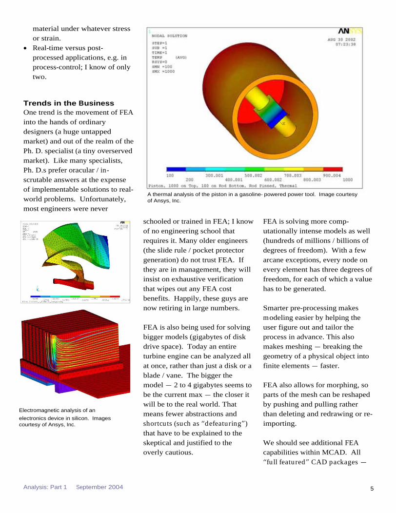
FEA is also being used for solving bigger models (gigabytes of disk drive space). Today an entire turbine engine can be analyzed all at once, rather than just a disk or a blade / vane. The bigger the model
2 to 4 gigabytes seems to be the current max
the closer it will be to the real world. That means fewer abstractions and shortcuts (such as defeaturing ) that have to be explained to the skeptical and justified to the overly cautious.
FEA is solving more comp-utationally intense models as well (hundreds of millions / billions of degrees of freedom). With a few arcane exceptions, every node on every element has three degrees of freedom, for each of which a
value has to be generated.
Smarter pre-processing makes modeling easier by helping the user figure out and tailor the process in advance. This also makes meshing
breaking the geometry of a physical object into finite elements
faster.
FEA also allows for morphing, so parts of the mesh can be reshaped by pushing and pulling rather than deleting and redrawing or re-importing.
We should see additional FEA capabilities within MCAD. All
full featured CAD packages
A thermal analysis of the piston in a gasoline- powered power tool. Image courtesy of Ansys, Inc.
Electromagnetic analysis of an
electronics device in silicon. Images courtesy of Ansys, Inc.

Analysis: Part 1 September 2004 6
from CATIA, UG, and PTC
have FEA capabilities. As you may know, UG recently bought a NASTRAN license from NASA.
Usually this means some limited meshing with just a few choices of elements and types of analyses, one solver, limited model size, and very limited pre-and post-processing. This is good for things like brackets and braces. Solid-modeler packages such as Inventor, Solid Edge and SolidWorks have minimal FEA powers.
Vice versa, we should also see better MCAD capabilities within FEA packages. This lets users manipulate geometry created elsewhere and avoids re-generating, which is error-prone and time wasting. This will be very useful for managing engineering changes.
Look for more integration with MCAD software. This usually means that a CAD wireframe (or solid or surfaced model) geometry can be imported directly into the FEA package and meshed with minimal geometry editing / deleting / cleanup. Then it can be solved and exported back to the MCAD package as engineering changes without translation or third-party tools such as IGES ( seamlessly, more or less).
Another trend is the rep-resentation of nonmetallic materials, especially engineering plastics, silicon rubber and non-homogeneous materials such as
wood. Traditionally, analysis soft-ware assumed it was analyzing homogeneous pieces of metal.
Look for analysis of assemblies whether bolted, riveted or welded, and parallel processing for really big models.
Multiphysics, which really comes down to two different analyses that are coupled to better represent what happens in the real world where physical phenomena are rarely isolated, is becoming more common. Typical pairings in multiphysics include the following:
Electro-Magnetic
Electro-Structural
Fluid-Structural
Fluid-Thermal
Magnetic-Structural
Magnetic-Thermal
Piezo-Acoustics
Piezoelectric
Structural-Acoustics
Thermal-Electric
Thermal-Stress
FEA is typically is a product (a software package) rather than a service, and is sold rather than leased. However many distributors and reps of FEA software vendors do offer analysis on contract.
Many distributors have their own software add-ons and plug-ins, too. In the ANSYS world, this includes firms like Phoenix Analysis & Design Technology (PADT in Arizona), CAEAI, and cd-Adapco in New York.
A mechanical analysis of a socket for socket wrenches. Image courtesy of Ansys, Inc.
Analysis: Part 1 September 2004 7
The ord inary MCAD person will get into FEA occasionally if he or she develops products and designs new things, especially if the new thing could
send a customer yelling in pain (or on a gurney) to a tort lawyer or
merely lead to a foreseeable warranty claim. If he or she is designing tooling, probably not.
In general, only the risky parts of risky designs are analyzed. Otherwise, existing standard practice and rules of thumb will suffice.
Extreme use is usually reserved for things whose failure would be catastrophic, i.e. certain auto parts,
airliners, turbines, helicopter gears, things that might explode, etc. Basic and extreme vary
from company to company and even user to user. In many
extreme cases, companies have
developed their own modelers and solvers that use a handful of different elements.
Personally, I don t think the question of languages is relevant any more. Most CAE software packages have their own scripting tools for macros and pre-
/ post-processors, such as for automating the feeding of values to a solver. All these packages run under Windows operating
systems, preferably XP for its stability, as well as under a few variants of UNIX and (in-
creasingly) Linux (probably not Java). Microsoft tools like Visual Basic are widely used. There is still a lot of Fortran code in CAE, however, but probably no Cobol anymore.
Jack Thornton spent several years
working with the engineering
simulation solutions provider
ANSYS, Inc. as a consultant.
Currently, he is the principal at
MINDFEED Marcomm, which
provides relational dynamics
consulting for technology
marketing. He can be reached via
e- mail at [email protected].
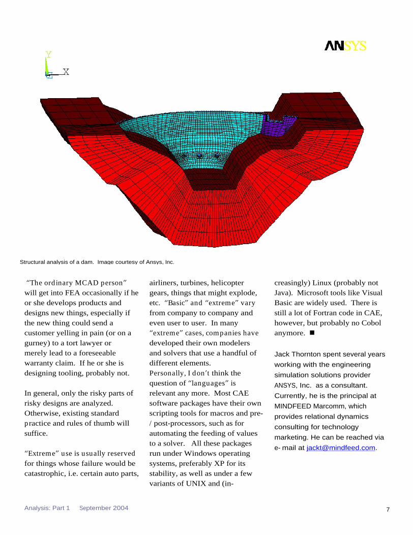
Structural analysis of a dam. Image courtesy of Ansys, Inc.

Analysis: Part 1 September 2004 8
Analysis: A Buyer s Guide
Contributed by Noran
Engineering, Inc.
Editor s Note: Noran Engineering,
Inc. graciously allowed us to adapt
their buyer s guide for this report .
Noran provides high- end analysis
tools priced for wide- scale use. Its
core product, NE/Nastran,
performs structural, dynamic, and
heat transfer finite element
analysis on very large, complex
models while requiring only
modest hardware resources. To
learn more about Noran, visit the
website at www.NENastran.com.
The world of analysis software can be confusing, and analysis options are deeply complex. With a myriad of similar products available with varying capabilities and price tags, making an informed purchasing decision can be difficult.
Use the following guide, in conjunction with our Analysis
Vendor Reference Guide, to ask
questions about analysis software before you make your purchase.
Consider the Common Solution Types If you re buying a complete solution, the software package should support the following common analysis solutions:

Analysis: Part 1 September 2004 9
Linear Statics
Nonlinear Statics with Large Displacement/ Rotation, Material Nonlinear, and Contact
Normal modes, with Optional Prestress (Stress Stiffening)
Buckling
Linear Transient, Frequency, and Random Response
Nonlinear Transient Response
Linear and Nonlinear Steady State Heat Transfer
Linear and Nonlinear Transient Heat Transfer
Some packages may require purchasing additional modules to complete some of the more complex analyses. Be certain you know what types of analysis you will be performing (current and future) when evaluating the software's capabilities and pricing.
Note that these are just the basics; if you are analyzing very complex problems, you might need a pre- or post-processor, specific solvers, or certain element types. Or you might have hardware issues, as analysis problems require large amounts of processing power. Use the following questions to determine your specific needs.
Is the Product Right For You? First, does it have the features you need? Ask your sales rep:
Can the software handle contact? Is this easy to set up and run?
Does the software support assemblies, shells, and solids?
Is the pre-processor compatible with all popular CAD software?
Is the software portable across various platforms and operating systems?
Does the software include its own scripting language for task automation?
Does it include its own parametric modeling language?
Is it integrated into the MCAD program you use? Does it read neutral file formats (ASIS, IGES, STEP, Parasolid)?
Is the printed and on-line documentation easily accessible? Is this documentation up to date and easy to use? Is it helpful? Are step-by-step examples provided?
Does the software support symmetry boundary conditions? If so, can the constraints be applied in an arbitrary coordinate system? Is this an inherent capability, or does this require special boundary elements, or some other complex manipulation?
What material models are supported? Are advanced models such as non-linear elastic and elasto-plastic supported? What about composite materials and laminates? Can temperature dependence be accounted for with all element types and all solutions?
How many elements are included in the software? Can elements of different types be mixed in the same analysis?
Are all supported element types included in the basic package, or is the purchase of more expensive options required to get more accurate (or better suited) elements?
Are all element types supported in all solution sequences?
Does the model have to be transferred between packages to add different elements, or loads?
Does the software have the ability to use shell elements for thin walled structures? Can solid geometry be midsurfaced to create shell meshes?
Does the software have an interpolation element (NASTRAN RBE3 or RSPLINE)?
Does the software have weld elements that allow easy joining of dissimilar meshes?

Analysis: Part 1 September 2004 10
Is pre- and post-processing accomplished in a single package?
Is the pre/post processor OpenGL optimized? Is it a native Windows application (was it designed for Windows, or ported over from Unix)?
Try a Product Demo Get a FULL product demonstration and an evaluation copy of the software to try.
Determine if the software package can run ALL the standard test cases and models you have or plan to create in the future. Evaluate the software's capabilities with your models. What is required if your analysis needs change? Will you have to purchase add-on modules, or an entirely new product?
Are the menus well organized, and are options easy to find? Are tasks such as changing views and rotating the part smooth and efficient?
How easy it to make changes to the model? Is this possible in both the pre-processor and the input file?
How is the product's performance on your computer? Does it often return insufficient memory errors? (Are there different solvers to choose from that are better suited to your computer or model?)
Does the automesher(s) create clean, well-conditioned meshes? Is this mesh visible and easy to repair manually? Does the solver report element geometry statistics? Does the
solver give warnings of bad or distorted elements?
Does the software support inertial relief? Do beam elements support shear-neutral axis offsets? How do they handle unsymmetrical and non-prismatic cross-sections?
Is the pre- and/or post-processor easy to use and efficient?
Buying Software is a Long-Term Investment. Do Your Due Diligence Where does the company's money go? What percentage goes to product development? Marketing? Shareholders?
How is the company run? Are the majority of the employees working in sales, support, or development? If a large percentage of the employees are sales staff, you may want to

Analysis: Part 1 September 2004 11
watch for sales tactics to push a poor or marginal product. Who will be available to handle your technical support needs as they arise? If the company has few developers, are they putting a focus on the R&D needed to keep their software up with new functionality?
Will you get
lost in the shuffle? When dealing with a large company, will your business receive personal attention regardless of the account size?
Don t Forget About Customer Service And Support How often are new versions released, and how much changes with each release? A new release can range from major upgrades to simple bug fixes. Don't confuse a quick fix with a new and innovative option ask about the company s R&D.
If you have a question or problem, whom can you contact? Are you forced to go through a sales rep, or can you reach the engineers and developers? Can you reach the engineers and developers while you are evaluating the product?
Is support available 24 hours a day, seven days a week? What is the turnaround time for problem resolution?
Are You Ready to Buy? Get a written quote that clearly shows what is included in the software package. Make sure
that any and all modules you need to accomplish your tasks are included in the quote. Beware of hidden costs that can make an attractive initial purchase price very costly in the long run. For example, get firm prices on maintenance and
upgrades. Also beware of varying levels of technical support! Commonly, companies constrain you to limited support based upon a lower purchase price or technical support limited to a certain number of calls and e-mails per year with substantial fees imposed for each additional call.
DO NOT accept a vendor-prepared model or demo as the only validation of the soft-ware's capabilities. Evaluate and review the software using the program installed on your computer with your models.
Summary: Think Twice Before You Buy Assess capabilities: Will the software perform the tasks you require now and in the future? Don t forget that your MCAD package may include analysis module(s) are they reasonable? Are they sufficient for your needs?
Reconcile the price: Is the software reasonably priced for the features you require? Beware of a low initial price on the base package that increases dramatically once you start adding on the modules you require.
Consider support and service: Will you get fast answers from knowledgeable engineering staff? Are you limited to a fixed number of free calls, then required to pay? When is support available? Is the level of support based upon your account size? Will you be treated like a valued customer after your purchase?
Consider the company s
reputation: How long have they been in business? Are they focused on analysis, and the type you will be using? Are they an innovative leader in the industry? What do their customers say about them?