Low Latency Random Access for Small Cell Toward Future ...
14
Received November 15, 2019, accepted December 1, 2019, date of publication December 12, 2019, date of current version December 23, 2019. Digital Object Identifier 10.1109/ACCESS.2019.2958991 Low Latency Random Access for Small Cell Toward Future Cellular Networks SUNDO KIM 1 , (Student Member, IEEE), SEONGWON KIM 2 , (Member, IEEE), JUNSEOK KIM 1 , (Student Member, IEEE), KITAEK LEE 1 , (Student Member, IEEE), SUNGHYUN CHOI 3 , (Fellow, IEEE), AND BYONGHYO SHIM 1 , (Senior Member, IEEE) 1 Department of Electrical and Computer Engineering and INMC, Seoul National University, Seoul 08826, South Korea 2 AI Center, SK Telecom, Seoul 04539, South Korea 3 Samsung Research, Samsung Electronics, Seoul 06765, South Korea Corresponding authors: Seongwon Kim ([email protected]) and Byonghyo Shim ([email protected]) This work was supported in part by The Cross-Ministry Giga KOREA Project funded by the Ministry of Science and ICT (MSIT) of Korea Government (Development of Ultra Low-latency Radio Access Technologies for 5G URLLC Service) under Grant GK18P0500, and in part by the Samsung Research Funding and Incubation Center for Future Technology of Samsung Electronics under Project SRFC-IT1901-17. ABSTRACT In future cellular networks, performance target includes not only increasing data rate, but also reducing latency. The current LTE-Advanced systems require four message exchanges in the random access and uplink transmission procedure, thus inducing high latency. In this paper, we propose a 2-way random access scheme which effectively reduces the latency. The proposed 2-way random access requires only two messages to complete the procedure at the cost of increased number of preambles. We study how to generate such preambles and how to utilize them. According to extensive simulation results, the proposed random access scheme significantly outperforms conventional schemes by reducing latency by up to 43%. We also demonstrate that computational complexity slightly increases in the proposed scheme, while network load is reduced more than a half compared to the conventional schemes. INDEX TERMS 5G, low latency, random access, small cell, uplink transmission. I. INTRODUCTION From 1G to 4G Long Term Evolution-Advanced (LTE-A), major goal of cellular systems was to achieve the through- put improvement over the previous generation. However, the goals of the fifth generation (5G) are diverse and way dif- ferent from the previous generations since the goals include the reduction of latency and error rate, support of mas- sive devices, along with the enhancement of broadband services. In accordance with these trends, ITU has classi- fied 5G services into use cases, namely, Enhanced Mobile Broadband (eMBB), Massive Machine Type Communica- tion (mMTC), and Ultra Reliable and Low Latency Com- munication (URLLC) [1]. While the primary purpose of the eMBB is to improve data rate, the main goals of the mMTC and URLLC are to enhance the connection density and the latency/reliability, respectively. Among three categories, satisfying the URLLC require- ment is perhaps most challenging since it is very difficult The associate editor coordinating the review of this manuscript and approving it for publication was Adnan Shahid . to meet the low latency and high reliability requirements at the same time. In fact, many of URLLC applications such as remote surgery, autonomous driving, and smart factory [2]–[5], tight end-to-end latency and also stringent reliability requirements should be guaranteed simultaneously. Due to the relentless increase in the number and types of things (e.g., machine, sensor, robot, drone, car), the uplink traffic is expected to increase rapidly, resulting in increased uplink/downlink ratio [6]. In these URLLC applications we mentioned, uplink transmission is becoming more important. Accordingly, the uplink latency as well as the downlink latency should be minimized to meet the stringent latency requirement. Furthermore, small cells and Ultra Dense Networks (UDNs) are becoming more and more popular as a promis- ing solution to support huge data traffic in 5G [7]–[9] and various applications including URLLC use cases are expected to be served through small cell evolved Node B (eNB). Therefore, it is of importance to come up with a low latency protocol supporting URLLC use cases in small cell networks. VOLUME 7, 2019 This work is licensed under a Creative Commons Attribution 4.0 License. For more information, see http://creativecommons.org/licenses/by/4.0/ 178563
Transcript of Low Latency Random Access for Small Cell Toward Future ...

Received November 15, 2019, accepted December 1, 2019, date of publication December 12, 2019,date of current version December 23, 2019.
Digital Object Identifier 10.1109/ACCESS.2019.2958991
Low Latency Random Access for Small CellToward Future Cellular NetworksSUNDO KIM 1, (Student Member, IEEE), SEONGWON KIM 2, (Member, IEEE),JUNSEOK KIM 1, (Student Member, IEEE), KITAEK LEE 1, (Student Member, IEEE),SUNGHYUN CHOI 3, (Fellow, IEEE), AND BYONGHYO SHIM 1, (Senior Member, IEEE)1Department of Electrical and Computer Engineering and INMC, Seoul National University, Seoul 08826, South Korea2AI Center, SK Telecom, Seoul 04539, South Korea3Samsung Research, Samsung Electronics, Seoul 06765, South Korea
Corresponding authors: Seongwon Kim ([email protected]) and Byonghyo Shim ([email protected])
This work was supported in part by The Cross-Ministry Giga KOREA Project funded by the Ministry of Science and ICT (MSIT) of KoreaGovernment (Development of Ultra Low-latency Radio Access Technologies for 5G URLLC Service) under Grant GK18P0500, and in partby the Samsung Research Funding and Incubation Center for Future Technology of Samsung Electronics under Project SRFC-IT1901-17.
ABSTRACT In future cellular networks, performance target includes not only increasing data rate, but alsoreducing latency. The current LTE-Advanced systems require four message exchanges in the random accessand uplink transmission procedure, thus inducing high latency. In this paper, we propose a 2-way randomaccess scheme which effectively reduces the latency. The proposed 2-way random access requires only twomessages to complete the procedure at the cost of increased number of preambles. We study how to generatesuch preambles and how to utilize them. According to extensive simulation results, the proposed randomaccess scheme significantly outperforms conventional schemes by reducing latency by up to 43%. We alsodemonstrate that computational complexity slightly increases in the proposed scheme, while network loadis reduced more than a half compared to the conventional schemes.
INDEX TERMS 5G, low latency, random access, small cell, uplink transmission.
I. INTRODUCTIONFrom 1G to 4G Long Term Evolution-Advanced (LTE-A),major goal of cellular systems was to achieve the through-put improvement over the previous generation. However,the goals of the fifth generation (5G) are diverse and way dif-ferent from the previous generations since the goals includethe reduction of latency and error rate, support of mas-sive devices, along with the enhancement of broadbandservices. In accordance with these trends, ITU has classi-fied 5G services into use cases, namely, Enhanced MobileBroadband (eMBB), Massive Machine Type Communica-tion (mMTC), and Ultra Reliable and Low Latency Com-munication (URLLC) [1]. While the primary purpose of theeMBB is to improve data rate, the main goals of the mMTCand URLLC are to enhance the connection density and thelatency/reliability, respectively.
Among three categories, satisfying the URLLC require-ment is perhaps most challenging since it is very difficult
The associate editor coordinating the review of this manuscript and
approving it for publication was Adnan Shahid .
to meet the low latency and high reliability requirementsat the same time. In fact, many of URLLC applicationssuch as remote surgery, autonomous driving, and smartfactory [2]–[5], tight end-to-end latency and also stringentreliability requirements should be guaranteed simultaneously.
Due to the relentless increase in the number and types ofthings (e.g., machine, sensor, robot, drone, car), the uplinktraffic is expected to increase rapidly, resulting in increaseduplink/downlink ratio [6]. In these URLLC applications wementioned, uplink transmission is becoming more important.Accordingly, the uplink latency as well as the downlinklatency should be minimized to meet the stringent latencyrequirement.
Furthermore, small cells and Ultra Dense Networks(UDNs) are becoming more and more popular as a promis-ing solution to support huge data traffic in 5G [7]–[9]and various applications including URLLC use cases areexpected to be served through small cell evolved Node B(eNB). Therefore, it is of importance to come up with a lowlatency protocol supporting URLLC use cases in small cellnetworks.
VOLUME 7, 2019 This work is licensed under a Creative Commons Attribution 4.0 License. For more information, see http://creativecommons.org/licenses/by/4.0/ 178563

S. Kim et al.: Low Latency Random Access for Small Cell Toward Future Cellular Networks
FIGURE 1. Latency in LTE-A systems.
Before we proceed, we briefly discuss the latency issue inLTE-A. In the LTE-A standard, two types of latency, i.e., con-trol plane latency and user plane latency, are defined [10](see Fig. 1). The control plane latency, caused by the randomaccess to set up an RRC connection, is the time requiredfor User Equipment (UE) to transit state from RRC_IDLEto RRC_CONNECTED.1 Whereas, the user plane latency,one-way transmission time from UE to eNB or vice versa,is due to the data transmission.While the downlink user planelatency occurs due to the scheduling and transmission latency,the uplink user plane latency, a.k.a. the uplink transmissionlatency, occurs due to the scheduling request as well as thescheduling and transmission delays. Note that the downlinkdata can be transmitted right after the scheduling but suchprocess is not possible for the uplink data. This is becausethe resource management is conducted by eNB so that UEshould request uplink resources to eNB for the uplink datatransmission. For these reasons, uplink transmission latencyis generally much larger than the downlink latency. Clearly,reduction of both uplink transmission latency and controlplane latency is crucial for the success of URLLC services. InLTE-A systems, Round Trip Time (RTT) for the data trans-mission is typically over 25 ms [12], [13], which apparentlydoes not meet the latency requirement for URLLC services.
We note that the reduction of core latency (the latencybetween eNB and core network) is also an important issue butwe do not consider it in this work since the primary purpose ofthis work is to propose a new random access scheme reducingthe control plane latency as well as the uplink transmissionlatency.
An aim of this paper is to propose a 2-way handshake-based random access employing the information-containedpreamble. In our work, we primarily consider the small cellscenario with sporadic traffic. Our major contributions aresummarized as follows:
1RRC stands for Radio Resource Control. There are two RRC states,namely, RRC_IDLE and RRC_CONNECTED. Data transmission or othermessage exchange can occur only in RRC_CONNECTED state, so that UEshould establish an RRC connection to become active [11].
• We propose a 2-way handshake-based random accessscheme replacing the conventional 4-way random accessand the uplink transmission procedure.
• We propose a new preamble structure supporting theproposed random access scheme that conveys specificinformation for UE.
• Using NS-3 system-level simulations [14], we show thatthe proposed 2-way random access scheme achievessignificant reduction (up to 43%) in the control planelatency and uplink transmission latency over the conven-tional random access.We further verify the effectivenessof the proposed scheme for various burst sizes and num-bers of UEs.
• We analyze the computational complexity of the pro-posed scheme and show that the proposed scheme hasslightly higher computational burden than that of theconventional schemes, yet achieves significant networkload reduction (i.e., over 50%).
The rest of the paper is organized as follows. We summa-rize related work in Section II. We discuss the conventionalLTE-A random access procedure and uplink transmissionprocedure with emphasis on the latency issue in Section III.In Section IV, we present the proposed 2-way random accessscheme and then we describe how to generate the proposedrandom access preambles in Section V. We evaluate the pro-posed scheme in various environments in Section VI. Finally,we conclude the paper in Section VII.
II. RELATED WORKIn [15], Laya et al. addressed the need to revisit design ofrandom access for the next generation cellular systems. Theyargued that the current random access mechanism wouldnot be suitable for supporting a large number of devices(e.g., mMTC scenario in 5G), and hence, cannot satisfy thelatency requirement of mission-critical applications.
In recent years, several studies to reduce the latency ofthe random access have been proposed. As specified in the3GPP [16], Access Class Barring (ACB) controls the ran-dom access probability in LTE-A. Depending on the latencyrequirement, several access classes are defined. eNB appliesdifferent access probability (i.e., barring factor) to differentaccess classes, and UE performs the random access based onits barring factor. If UE does not perform the random access,UE performs the backoff procedure using barring time. Fur-thermore, Extended Access Barring (EAB) is introduced toincrease the success probability by preventing certain accessclasses from attempting random access. In addition to differ-ent access classes, EAB categories are used to further distin-guish UE types, e.g., smartphones or machine type devices.Network latency (time to complete the random access for allUEs) can be reduced by increasing the success probabilityin both ACB and EAB. However, both ACB and EAB donot directly reduce the random access latency, which is therequired time for a single random access. This is because both
178564 VOLUME 7, 2019

S. Kim et al.: Low Latency Random Access for Small Cell Toward Future Cellular Networks
ACB and EAB focus on reducing the random access failurerather than reducing the random access latency itself.
Zhou et al. proposed a random access scheme with Trans-mission Time Interval (TTI) bundling [17]. While ACBincreases the success probability by controlling the numberof attempts for the random access, TTI bundling schemeenhances the success probability for a given number ofattempts. In essence, key idea behind this scheme is to trans-mit multiple preambles to enhance the success probabilityof the random access. To be specific, a UE sends randomlyselected preambles in consecutive subframes to perform therandom access. If one of these preambles is received bythe eNB, the random access is finished. This scheme reducesthe network latency as a result of the improved success proba-bility. However, similar to ACB and EAB, it does not directlyreduce the latency caused by the random access.
Recently, a low latency random access schemes have beenproposed. In [18], a 2-step random access scheme, which iscompleted by exchanging two messages, has been proposed.However, how to enable this scheme is not explained inthis work. Furthermore, this scheme is very sensitive to thecollisions.
A reduction of the uplink transmission latency is anotherimportant issue. A major latency component in the uplinktransmission is the latency in the scheduling process.One simple approach to reduce the uplink transmissionlatency is to eliminate the scheduling process. For exam-ple, a contention-based uplink transmission using a pre-scheduling has been proposed to reduce uplink transmissionlatency [19]. In [20], 3GPP developed Early Data Trans-mission (EDT) mechanism to support infrequent small datapacket transmission for Narrow Band Internet of Things(NB-IoT) and LTE Machine Type Communication (LTE-M).EDT mechanism enables the uplink data transmission in thethird message during the random access procedure. Notethat the random access procedure consists of four messageexchanges (see the detailed explanation in Section III-A). Adrawback of these schemes is that a reliable transmission isnot guaranteed due to collisions.
Au et al. proposed a pre-scheduling uplink trans-mission scheme, called Sparse Code Multiple Access(SCMA), to mitigate collision events [21]. In our previ-ous work, we also proposed pre-scheduling transmissionschemes [22], [23]. In these schemes, uplink resources areallocated when the RRC connection is established and theuplink resources are pre-scheduled based on its own algo-rithm. In [24], pre-scheduling protocol has been proposedin Large-Scale Antenna Systems (LSAS). Theses schemesfocus on the reduction of the uplink latency and effec-tively reduce uplink latency by using pre-scheduled uplinkresources. However, the most important assumption of theseschemes is that all UEs are in the RRC_CONNECTED stateto maintain the uplink synchronization. Thus, a potentialdrawback of these schemes is that the uplink synchronizationshould be guaranteed to maintain the RRC connection. Thisis not suitable for a situation in which the UE transits the RRC
FIGURE 2. Random access and uplink transmission procedure in LTE-A.
state depending on the presence or absence of traffic. In con-trast to theses schemes, our proposed scheme directly reducesuplink transmission latency even if uplink synchronization islost.
III. RANDOM ACCESS AND UPLINK TRANSMISSIONPROCEDURE IN LTE-AIn this section, we discuss the random access and uplinktransmission in LTE-A systems and then analyze the latencyproblem of the conventional procedures. Through a con-crete investigation, we emphasize the necessity of 2-wayhandshake-based random access as an effective way to reducelatency.
A. RANDOM ACCESS IN LTE-AThe main purposes of the random access are to establishthe RRC connection and to maintain the uplink synchroniza-tion. Note that the RRC connection should be maintainedto transmit data. In LTE-A, two types of random accessprocedures are defined, i.e., contention-based random accessand contention-free random access.
1) CONTENTION-BASED RANDOM ACCESSFig. 2(a) depicts the contention-based random access proce-dure in LTE-A [25]. Four message exchanges are required tocomplete the random access:
1) Preamble transmission: Among 64 different pream-bles, UE randomly selects one and then sends theselected one to the eNB. This preamble is transmittedthrough Physical Random Access Channel (PRACH).The preamble is transmitted in a pre-defined sub-frame determined by the eNB. Since each UE ran-domly selects its own preamble, multiple UEs can sendthe same preamble simultaneously. The simultaneoustransmission of the same preamble from multiple UEsis called collision. Even though the eNBmight success-fully detect the preamble, the eNB cannot differentiatethe collission-expriencing UEs by receiving a singlepreamble.
VOLUME 7, 2019 178565

S. Kim et al.: Low Latency Random Access for Small Cell Toward Future Cellular Networks
2) Random Access Response (RAR): After receivinga preamble successfully, the eNB sends a RandomAccess Response (RAR) message to grant resourcesfor the third message to the UE(s). RARmessages con-tain the preamble identifier (ID), Timing Advancement(TA) command used for the uplink time synchroniza-tion, and uplink resources for the third message. If theUE finds its preamble ID in the received RAR, thenthe UE prepares the third message. Otherwise, the UEdeclares the failure of the random access and retries therandom access after the backoff process.
3) L2/L3message transmission:After receiving an RARmessage containing its preamble ID, the UE transmitsan L2/L3 message (e.g., RRC connection request) withits 48-bit long contention resolution ID using the uplinkresources allocated through the RAR. Note that the UEdetermines the contents of the L2/L3 message depend-ing on the purpose of the random access. If a collisionhappens at the first message transmission (i.e., pream-ble transmission), then the collided UEs can transmitthe L2/L3 message, i.e., the third message, using thesame resource.2 In this case, the eNB apparently cannotsuccessfully decode the third message.
4) Contention resolution: If the eNB receives the thirdmessage successfully, then it transmits the fourth mes-sage including the 48-bit long contention resolution IDreceived from the UE. If the UE receives the fourthmessage successfully with the UE’s contention reso-lution ID, then the UE completes its random accessprocedure. However, if the UE fails to find its ID in thefourth message, then the UE should restart the randomaccess procedure after a backoff, which takes around10 ms.
2) CONTENTION-FREE RANDOM ACCESSWhen a UE maintains the RRC connection, the eNB canrealize the existence of the UE. If the eNB determines thatthe UE should perform the random access, the eNB assigns aspecific preamble to the UE. In contrast to the contention-based random access, the eNB initiates the random accessin the contention-free random access. Due to the use of theassigned preamble, collision can be completely avoided sothat this procedure is completed by exchanging two mes-sages (i.e., preamble and RAR). Note that the preamblefor the contention-free random access cannot be used forthe contention-based random access. This is because a partof preambles is reserved only for contention-free randomaccess.
B. UPLINK TRANSMISSION PROCEDUREWhen the RRC connection is established or maintained, UEcan transmit data. Otherwise, UE should establish the RRC
2We do not consider capture effect for simplicity. That is, if the samepreamble is transmitted by multiple UEs, eNB receives none of the trans-mission successfully, so that all the corresponding UEs should restart randomaccess.
connection before the data transmission. In the uplink trans-mission, the most important message is Buffer Status Report(BSR) message.3 UE should first transmit a BSR messageto indicate the amount of pending uplink data. Based onthe BSR, the eNB allocates Physical Uplink Shared Channel(PUSCH) resource. Overall, uplink transmission procedurecan be classified into three cases:A. When the PUSCH resources are allocated.B. When the PUSCH resources are not allocated, but the
Physical Uplink Control Channel (PUCCH) resourcesare allocated.
C. When the PUCCH resources are not allocated inRRC_CONNECTED.
Case A:This case occurs onlywhen there is ongoing uplinkdata transmission. UE transmits its data by piggybackingBSR on PUSCH. In doing so, the eNB can allocate thePUSCH resources based on a received BSR.Case B: If the PUSCH resources are not allocated to
UE, UE does not have resources to transmit the BSR mes-sage. Instead of directly transmitting the BSR message, UEsends the Scheduling Request (SR) message on PUCCH [19].An uplink transmission procedure initiated by SR is depictedin Fig. 2(b):
1) Scheduling Request (SR): SR is one-bit informationindicating whether the UE has data in its buffer or not.If UE has an uplink data to transmit, the UE transmitsan SR (via PUCCH) to its eNB.
2) Uplink Grant: After receiving the SR, the eNB grantsPUSCH resources to the UE. Since the resource allo-cation is an implementation issue, eNB might grant asmall amount of resources for the efficient resourceutilization.
3) BSR transmission: The UE transmits a BSR messageusing the granted resources after successfully decodinguplink grant message.
4) Scheduling: After receiving the BSR, the eNB canefficiently allocate the PUSCH resources to the UE forthe uplink data transmission.
Case C: Even if the PUCCH resources are not allocated toUE, UE can send the scheduling request through a randomaccess procedure. In this case, UE transmits a random accesspreamble instead of SR. After receiving a RAR success-fully, a BSR message is transmitted as the third messagein Fig. 2(a).
C. LATENCY ISSUE IN LTE-AIn this subsection, we discuss the rationale behind four mes-sage exchanges in LTE-A systems.
First, exchanging four messages is required when theUE switches from RRC_IDLE state to RRC_CONNECTEDstate. This is because eNB cannot identify how many UEstransmit the same preamble only by decoding the preamble
3Buffer status of UE represents the amount of uplink data in bytes. UEselects a value of its data range from a predefined table, and then reports thevalue to eNB in a form of BSR.
178566 VOLUME 7, 2019

S. Kim et al.: Low Latency Random Access for Small Cell Toward Future Cellular Networks
FIGURE 3. Concept of the proposed random access preamble.
(recall our discussion in Section III-A). Moreover, it is notpossible to identify which UE transmits a preamble due to therole of random ID. To resolve this issue, contention resolutionsteps (the third and fourth messages) are required. After thecontention resolution, eNB guarantees the completion of ran-dom access procedure for a single UE. In summary, exchang-ing fourmessages is unavoidable in the current random accessprocess, so that it is very difficult to reduce the latency by asmall makeshift of the current process.
Second, exchanging four messages is required to transmituplink data, which also incurs large latency. eNB cannot iden-tify UE’s buffer status based on the received SR. Therefore,eNB might grant a small amount of PUSCH resources totransmit a BSR to the UE. After receiving the BSR, eNBcan allocate accurate amount of resources. Moreover, whenthe uplink transmission is initiated from the random access,latency issue will be severe due to the contention-based ran-dom access.
One can deduce from this discussion that the reductionof the number of message exchanges would be a viableoption to reduce the latency. In fact, the key feature ofthe proposed method is the 2-way handshake-based randomaccess scheme, which simplifies the complicated messageexchange process in LTE-A, thereby achieving significantlatency reduction.
IV. PROPOSED RANDOM ACCESSIf we generate a single message containing both the first andthe third messages in Fig. 2, we can complete both randomaccess and uplink transmission procedure by exchanging onlytwo messages. In the conventional random access, eNB con-verts the physical random access preamble to the randomaccess preamble IDwhen eNB transmits a RARmessage. Forexample, 64 different preambles are mapped to 6-bit pream-ble IDs, i.e., bit index from ‘‘000000’’ to ‘‘111111.’’4 Keyidea of the proposed random access scheme is to add addi-tional bits to the preamble to simplify the message exchangeprocess. In the following subsections, we describe details ofthe proposed scheme.
A. KEY IDEAFig. 3 depicts the main idea of the proposed random accesspreamble. The proposed preamble consists of two parts,
4L-bit preamble means that a single preamble is represented by L bits, sothat 2L different preambles exist.
namely, information part and identifier (ID) part. Key featureof the proposed preamble is to include both the identifier andinformation. This is in contrast to the conventional randomaccess where the preamble contains a random identifier cho-sen from the predetermined set of preambles. In a nutshell,the proposed preamble contains the information in the thirdmessage of the conventional scheme to reduce the messageexchanges. To prepare a proper response containing the sec-ond and the fourth messages in the conventional procedure,information bit should represent all the possible informationof the third message. Therefore, we need to categorize thepreamble depending on which information is contained. Wewill discuss this in detail in the next subsection.
In order to utilize the information of UE based on thereceived preamble, the eNB has to make sure that the pream-ble is transmitted only by a single UE. This means thatinformation part becomes useful only when the bit index forID part is selected by a single UE. To resolve this problem,ID part should be uniquely dedicated to each UE. Oncethe UE performs the random access for the initial access,the eNB allocates ID part to the UE. After the ID part allo-cation, the UE selects the preamble among the pre-allocatedpreamble set based on the UE’s information. For example,if ‘‘00100100’’ is the allocated ID part of a UE, the allocatedpreamble set consists of the preambles with the eight leastsignificant bits of ‘‘00100100’’, i.e., from ‘‘000000100100’’to ‘‘111100100100’’ assuming four-bit information part. InFig. 3, information part is ‘‘1001,’’ so that the preamble bitindex is ‘‘100100100100.’’
B. PROPOSED PREAMBLE AND CATEGORIZATIONIn the conventional procedure, the third message conveysdifferent set of information for the different purpose of ran-dom access. Therefore, we categorize the proposed preambledepending on the purpose of random access.
In order to deliver information part, 6-bit preambles usedfor the conventional random access are not enough. Note thatif three out of six bits are used as information part, onlyeight UEs can be identified using the remaining three bits.In order to serve a proper number of UEs and at the sametime deliver information of UE, we propose a new preamblestructure using larger number of bits than the conventionalrandom access preamble. Depending on the target numberof UEs in a cell, the number of preambles can be adjustedadaptively.
Without loss of generality, we assume that 12-bit pream-ble is used (see Fig. 3). By increasing the preamble size,we can indicate specific information in certain bit index. Inthe conventional random access, major information in thethird message is the control element which depends on thepurpose of random access. Buffer status of UE is an impor-tant information for the uplink transmission since the uplinkresource is allocated by eNB based on the reported bufferstatus of UE. Considering these, we design the proposedpreamble such that it contains two types of information: thepurpose of random access and buffer status of UE. Before
VOLUME 7, 2019 178567

S. Kim et al.: Low Latency Random Access for Small Cell Toward Future Cellular Networks
explaining the proposed preamble categorization, we brieflydiscuss when UE performs the random access in LTE-A.
1) PURPOSE OF THE RANDOM ACCESSThe random access is performed for the following events [25].
(a) Initial access(b) RRC connection re-establishment procedure(c) Handover(d) Downlink data arrival during RRC_CONNECTED
when uplink synchronization is lost(e) Uplink data arrival during RRC_CONNECTED when
uplink synchronization is lost(f) For positioning purpose
Since both eNB and UE can trigger the random access,there are basically two types of random access. First, eNBtriggers the random access for the events (c), (d), and (f).These events employ the contention-free random access.One reason that the eNB triggers the random access is tocontrol the uplink timing advancement for these events. Inevent (c), another reason is to support UE with better qualityof service (QoS) by performing handover to another eNB.In event (a), (b), and (e), UE triggers the contention-basedrandom access. Both event (a) and (b) occur for the RRCconnection request. Specifically, event (a) occurs when theUE initially accesses the cell. For example, whenUE is turnedon, UE performs the random access for the initial access.On the other hand, event (b) occurs when the current UE’sRRC state is RRC_IDLE and UE completed its initial accessonce in the past. If UE has the uplink data to transmit whenthe uplink synchronization is lost, UE performs the randomaccess to control the uplink timing and also to notify its bufferstatus to eNB.
2) PROPOSED PREAMBLE CATEGORIZATIONCovering all aforementioned events, we categorize the pur-poses of random access into four different cases.
(i) Initial access(ii) Random access triggered by eNB(iii) Random access triggered by UE(iv) Uplink data arrival
a: INFORMATION PART 1 - THE PURPOSE OF RANDOMACCESSPreambles can be allocated to UE only after the initial access,and hence, a certain number of preambles should be reservedfor the initial access. In the proposed scheme, contention-based random access is still performed for the initial access.Similarly, a certain number of preambles are reserved forcase (ii). This case corresponds to events (c), (d), and (f), andeNB can further categorize the preambles according to thespecific events. When the handover is performed, the servingeNB can transfer the information related to preambles whichare used for handover purpose via X2 interface. By doing so,the target eNB can easily recognize the UE performing thehandover. When the preambles used in case (iii) are detected
TABLE 1. Example of preamble categorization.
at eNB, eNB recognizes the fact that UE triggers the randomaccess for the event (b). We further differentiate the uplinkdata arrival case, i.e., case (iv), from case (iii) because UEshould report its buffer status to eNB in case (iv), whichcorresponds to event (e). A detailed preamble categorizationexample with respect to information bit index is presentedin Table 1.
As shown in Table 1, the purpose of random access is deter-mined by the beginning part of the bit index. For example,if UE starts random access procedure for initial access, UEshould select a preamble starting with bit index ‘‘00.’’ Sincethere are 1,024 different preambles for the initial access,collision probability can be reduced significantly comparedto the conventional random access with 64 preambles.
b: INFORMATION PART 2 - BUFFER STATUSIf the UE performs the random access for uplink data arrival,the proposed preamble contains the current buffer status aswell as the purpose of random access. Accordingly, eNB canefficiently allocate uplink resources based on the buffer statusof UE.
3GPP defines 6-bit buffer status reporting values [26].In the proposed scheme, we combine the conventionalLTE-A buffer status to represent reduced bit information.The example to use the 3-bit buffer status is presentedin Table 2. If the received preamble indicates the uplinkdata arrival, then eNB identifies the UE’s buffer status usingthe additional bits. Consequently, eNB can accurately allo-cate uplink resources to the UE. We note that the proposedscheme can also support a transition from RRC_INACTIVEstate [27]5 to RRC_CONNECTED state. The transition fromRRC_INACTIVE state to RRC_CONNECTED state usu-ally occurs when the downlink or uplink data arrives. Forthis reason, case (ii) and case (iv) include a transition fromRRC_INACTIVE state to RRC_CONNECTED state.
c: SUMMARYAs shown in Fig. 4, the proposed random access reducesthe number of message exchanges. For the initial access,the proposed random access significantly reduces collisionprobability thanks to the increased number of preambles.After completing the initial access, the eNB allocates a setof unique preambles to the UE. At this point, the UE canperform the random access without collision due to uniquely
5RRC_INACTIVE state is newly defined RRC state, which maintainsRRC connection while minimize signalling and power consumption at thesame time.
178568 VOLUME 7, 2019

S. Kim et al.: Low Latency Random Access for Small Cell Toward Future Cellular Networks
FIGURE 4. The proposed 2-way random access procedure (right)compared to conventional 4-way random access (left).
TABLE 2. Example of approximate UE buffer status.
assigned preambles.Whenever the UE performs the proposedrandom access, the UE selects the preamble from the set ofassigned preambles. TheUE combines information bits basedon the purpose of random access with assigned preamble.Buffer status of the UE is further included if the purpose ofrandom access is uplink data arrival. Then, eNB can transmitthe proper RAR based on the acquired information, whichincludes both the second and the fourth messages in the con-ventional procedure. Therefore, the proposed random accesscan be completed by exchanging only two messages, whichalso can replace both the conventional random access andthe uplink transmission procedure. Due to reduced number ofmessage exchanges, the proposed random access can achievethe significant latency reduction.
V. PREAMBLE SEQUENCE ANALYSISIn this section, we describe how to generate the preamblesequence of the the proposed scheme. We also describe howto detect the proposed preamble and provide the detectionperformance of the proposed preamble via simulation.
A. PREAMBLE SEQUENCE GENERATION IN LTE-AIn this section, we first describe the conventional randomaccess preamble, and then describe the extended preamblesfor the proposed scheme. For the random access pream-ble, Zadoff-Chu (ZC) sequence is employed in LTE-A.ZC sequences have Constant Amplitude, and Zero Auto-Correlation (CAZAC) property. Furthermore, the cross
correlation of two different ZC sequences is very low.6 ZCsequence is defined in the 3GPP standards as follows [29]:
xu(n) = e−jun(n+1)NZC , 0 ≤ n ≤ NZC − 1, (1)
where NZC is the sequence length, and u is the root sequenceindex. This sequence is also called uth root sequence. Thereare two approaches to generate orthogonal the sequences. Thefirst method is to generate multiple root sequences by usingmultiple root sequence index. Note that the root sequenceindex is the cell-specific information, meaning that differentroot sequences are used in different cells. The second one isto generate a set of orthogonal sequences from a single rootsequence by cyclic shifting as
xu,v(n) = xu((n+ Cv) mod NZC
), (2)
where
Cv=
{vNCS , v=0, 1, . . . ,
⌊NZC/NCS
⌋− 1, NCS 6= 0,
0, NCS = 0.(3)
The maximum value of v is bNZC/NCSc − 1, so thatbNZC/NCSc − 1 orthogonal preambles are generated froma single root sequence. NCS is the minimum cyclic shiftingvalue satisfying orthogonality when the receiver detects twosequences. Because of the time uncertainty of UEs, differentNCS values are used depending on cell size. The number ofdifferent preambles generated from a single root sequencedepends on the value of NCS which satisfies the followingcondition [30].
NCS ≥[(
203r + τds
)NZCTSEQ
]+ ng, (4)
where r is cell size (km), τds is the maximum delay spread(µs), TSEQ is sequence length in time domain (µs), and ng isthe number of additional guard samples due to the receiverpulse shaping filter. Note that TSEQ is defined in the standard,and ng is generally assumed as 2.Since eNB broadcasts root sequence index u andNCS based
on its cell size, UE can generate 6-bit preambles by cyclicshifting from the given root sequence. If UE cannot generate6-bit preambles from a single root sequence due to the largeNCS , UE generates preambles from another root sequenceuntil 6-bit preambles are generated. The number of preamblesgenerated by a single root sequence is Nr = bNZC/NCSc. Asa result, in order to generate 64 different preambles, we needd64/Nre root sequences.
B. PROPOSED PREAMBLE SEQUENCE GENERATIONWhen we extend 6-bit preambles to 12-bit preambles,4,096 distinct preambles should be generated. To increasethe number of preambles, 1) a smaller value of NCS can beused,7 and/or 2) an increased sequence length NZC can be
6Let NZC be a prime number. If we create two ZC sequences and takethe correlation of the two sequences, the result meets lower bound, which is1/√NZC [28].
7The smallest value of NCS defined in the standard is 13
VOLUME 7, 2019 178569

S. Kim et al.: Low Latency Random Access for Small Cell Toward Future Cellular Networks
used. Because the propagation delay is less than that in macrocell, a smaller value of NCS can be adopted in small cellenvironments. Consequently, a larger number of preamblescan be generated from a single root sequence in the small cellenvironments. In order to increase the sequence length, moresubcarriers are needed. There are two options to increase thenumber of subcarriers. The first option is to use more fre-quency resources and the second one is to reduce subcarrierspacing by extending the sequence length in time domain.Since our goal is to reduce the latency, the first one is pre-ferred. Sequence length should be a prime number to satisfylow cross correlation property. In this work, we use both 1)and 2) to generate the proposed random access preambles.
Different root sequence indices are used to classify dif-ferent cells, and hence, we have to consider the number ofneighboring cells. Let M be the number of neighboring cellswhose coverage are overlapping. Let λcell (cells/km2) be thecell density. If we assume that small cells are uniformlydistributed, then M is approximately given by
M ≈ bπ (2r)2λcellc (5)
Note that small cells are highly overlapping andλcell > 103 cells/km2 in typical UDN scenario [31], [32].Since the eNB uses the different root sequence indices with itsneighboring cells,Nar (the available number of root sequenceindices) is given by
Nar = b(NZC − 1)/Mc = b(NZC − 1)/b4πr2λcellcc. (6)
We have to increase the sequence length if the number of rootsequence indices is not sufficient to generate 12-bit preamblesin the whole cells. The proposed preamble sequence basicallyadopts smaller NCS value. Because the delay spreads of thesmall cell environment for the LOS and NLOS are 0.065 µsand 0.129 µs, respectively, we choose τds to cover bothcases [33]. Depending on the cell size, the minimum valueof NCS can be calculated from (4) as
NCS = d6.99r + 0.14+ nge for NZC = 839
= d14.16r + 0.27+ nge for NZC = 1699 (7)
Now, Nr different preambles are generated from a singleroot sequence index and Nr is constant even if we increasesequence length NZC . This is because NCS is roughly pro-portional to NZC for a given cell size. In order to generate4,096 different preambles, NZC is selected by the followingequation. ⌈
4096⌊NZC/NCS
⌋⌉ ≤ ⌊NZC − 1M
⌋, (8)
where NZC should be a prime number satisfying (8).In PRACH, the sequence length in time domain is 800 µs,
and hence, the frequency spacing for PRACH, denoted by1fRA, is 1.25 kHz. Because we need NZC subcarriers, NZC ·1fRA (kHz) is required to generate the preamble sequences.If we align the order of Resource Blocks (RBs), F =
⌈NZC ·
1fRA/180⌉RBs are required in the proposed PRACH.8 As
a result, NZC subcarriers are used for the sequence elementtransmission and the remaining subcarriers are used for guardsubcarriers.
We set the parameter for the proposed preamble as follow-ing steps.
1) Find the minimum NCS based on given r and initialsequence length NZC from (7).
2) Validate (8) based on given initial NZC , M and NCS . Ifnot, find NZC satisfying (8) based on givenM and NCS .
3) Find the optimal NCS based on the procedure explainedin Section V-C.
4) Validate whether NZC and NCS satisfy (8) or not. If not,repeat from step 1) to step 4).
As an example, we consider the conventional preambledesign (NZC = 839). We can obtain the minimum NCS = 3from step 1). For a small cell with radius of 100 m, we haveM = 125 and 6 in the UDN scenario (λcell = 1000) andLTE small cell scenario (λcell = 50), respectively [34]. Forexample, if M = 6, the conventional preamble design cansupport the proposed scheme in the LTE small cell scenariofrom step 2). However, when M = 125, we see that NZCshould be modified in the UDN scenario from step 2). Afterselecting NZC , optimal NCS is determined from step 3). Fromstep 4), the final values ofNZC andNCS are determined. Fromthese discussions, we can conclude that the conventionalpreamble design can support the proposed scheme in LTEscenario. However,NZC should be enlarged in UDN scenario.
C. PROPOSED PREAMBLE DETECTIONIn this section, we evaluate the detection ratio of the proposedpreamble in the small cell environments. When a receiverdetects a preamble, the receiver can benefit from the CAZACproperty by computing Power Delay Profile (PDP) throughcyclic cross-correlation. The PDP of a received sequence atlag l is given by
PDP(l) =
∣∣∣∣ NZC−1∑n=0
y(n)xu∗(n+ l)NZC
∣∣∣∣2
, (9)
where y(n) is the received sequence and xu(n)NZC is a ref-erence sequence with the length of NZC , and (·)∗ denotesthe complex conjugate. If PDP of the signal is larger than adetection threshold during searching window with the lengthof NCS , eNB detects a preamble and determines the value ofNCS . By doing so, eNB coverts the physical sequence to apreamble ID, which represents the additional information aswell as the UE-specific ID. We used the multi-user detectionscheme in [35].
In order to validate the proposed preamble transmission,we conduct a link-level simulation using MATLAB. UEsare uniformly distributed within a cell coverage in a singlecell environment. Fig. 5 shows the detection ratio when the
8One LTE-A RB bandwidth is equal to 180 kHz.
178570 VOLUME 7, 2019

S. Kim et al.: Low Latency Random Access for Small Cell Toward Future Cellular Networks
FIGURE 5. Preamble detection ratio.
sequence length NZC is set to be the same as the conventionalLTE-A preamble (i.e., NZC = 839). Fig. 5(a) presents thepreamble detection ratio for a given cell coverage as a func-tion of NCS in a small cell environment. As the cell coverageincreases, the detection ratio decreases due to the effect ofpropagation delay. However, the detection ratio forNCS beingsmaller than 10 is acceptable in small cells.
Furthermore, we simulate in the worst interference situa-tion to evaluate the preamble detection performance. Thereare two edge UEs, i.e., target edge UE and interfering edgeUE, which communicate with target eNB and interferingeNB, respectively. Target edge UE transmits preamble totarget eNB while interfering edge UE transmits preambleto interfering eNB. Target edge UE and interfering edgeUE located at the same location use preambles generatedfrom different root sequence indices. Both target eNB andinterfering eNB are located at the same distance from theUEs on exactly opposite directions. Interfering edge UEinterferes target eNB, and hence, target eNB detection per-formance might be degraded. Fig. 5(b) depicts the preambledetection ratio for target eNB when neighboring interferenceexists. The result shows that the preamble detection ratioslightly decreases for the same coverage and NCS value com-pared to Fig. 5(a). This means that preamble detection is abit affected by interfering preamble because different rootsequence indices are used. However, we should select NCSsatisfying preamble detection ratio being larger than the pre-defined threshold (e.g., 99% detection ratio) in the proposedscheme. We conclude that smaller NCS value than 13, whichis the minimum value defined in the standard, can be adoptedin order to generate 12-bit preambles in small cell networks.
We also validate the detection ratio for larger values ofNZC(i.e., NZC = 1699) (see Fig. 5(c) and (d)). The result showsthat a large NCS is required to detect preambles comparedto the case that NZC is equal to 839. However, we verifythat Nr remains almost the same in such a case. To be spe-cific, the number of preambles generated from a single root
FIGURE 6. Preamble detection ratio when multiple UEs transmitspreamble.
FIGURE 7. False alarm ratio when multiple UEs transmits preamble.
sequence index remains the same, but more root sequenceindices are available.
Lastly, we further validate the detection performance whenmultiple UEs transmit the proposed preamble. Note that weconsider 2-tier hexagonal topology and verify the perfor-mance of the central eNB with 1,000 times iterations. Weconsider four cases depending on how to select the rootsequence as follows.
• All UEs generate preamble from a single root sequence.• UEs generate preamble from one of two root sequenceswith balanced ratio (i.e., 1:1 ratio).
• UEs generate preamble from one of two root sequenceswith unbalanced ratio (i.e., 3:7 ratio).
• All UEs generate preamble from different rootsequences.
As shown in Fig. 6, the preamble detection performanceis better than 99% by the proper choice of NCS . In thissimulation, we set NZC = 1699. The value of NCS satisfy-ing detection ratio being larger than pre-defined threshold(i.e., 99%) is the same for 200 m coverage case and slightlyincreases for 500 m coverage case compared with the resultof Fig. 5. From this study, we can observe that smaller NCSvalues can be adopted to generate the proposed preamble insmall cell networks.
We also validate the false alarm ratio in the same scenario.The result in Fig 7 shows that the preamble transmission withthe multiple root sequence indices affects the uncorrelatednoise which results in increasing the false alarm ratio. Still,
VOLUME 7, 2019 178571

S. Kim et al.: Low Latency Random Access for Small Cell Toward Future Cellular Networks
FIGURE 8. Average network latency for initial access.
we can select the proper value of NCS to achieve both highdetection ratio and low false alarm ratio.
VI. PERFORMANCE EVALUATIONWe conduct various simulations to evaluate the proposedrandom access scheme using MATLAB and NS-3. Becausewe validate the proposed preamble detection performance inthe prior section, we assume that the preamble detection isperfect. The following four metrics are considered:• We evaluate initial random access in order to confirmthat the proposed random access achieves significantlatency reduction.
• We evaluate the proposed random access in terms ofend-to-end latency for uplink transmission with varioussettings (i.e., burst size, the number of UEs in a cell).
• We validate the network load when the number of simul-taneously transmitting UEs varies.
• We compare the computational complexity of the pro-posed scheme and conventional schemes.
In the NS-3 simulation environment, we have 19 eNBs withhexagonal topology [36], and UEs are randomly placed ineach cell. The detailed values related to NS-3 simulation aresummarized in Table 3. In order to develop realistic simula-tion environment, we adopt WINNER II channel model [37].We evaluate the performance under the sporadic traffic ratherthan full-buffered traffic model [38]. Some parameters in thetable, e.g., the number of UEs in each cell and burst size,vary in some simulation scenarios. Unless stated otherwise,the values in Table 3 are used.
A. NETWORK LATENCYFig. 8 depicts the network latencywith error bar9 as a functionof the number of UEs in a single cell environment. Networklatency is the latency until all UEs complete their randomaccess procedure. We observe that the proposed schemeachieves the lowest latency. Collision probability increaseswith the number of UEs, thus incurring significant latencyincrease in Conv. RA scheme.
Meanwhile, the proposed scheme significantly reducescollision probability because of the increased number ofpreambles, thus resulting in significant latency reduction. In
9Error bar always represents the standard deviation in this paper.
TABLE 3. Summary of NS-3 simulation parameters.
FIGURE 9. Empirical CDF of one-way latency.
Conv. RAw/ bundling scheme, latency reduction comes frommultiple random access attempts in contiguous subframes.However, collision is unavoidable as the number of UEsincreases due to the small number of preambles. As a result,network latency performance is worse than the proposedscheme. Therefore, we conclude that the proposed schemesignificantly outperforms comparison schemes in terms oflatency.
B. ONE-WAY LATENCYFig. 9 presents the empirical Cumulative Distribution Func-tion (CDF) of one-way latency for the proposed scheme andthe comparison schemes. The one-way latency is definedas the time interval from the point where a packet arrivesat application layer of a source (UE) to the point where adestination (server) receives the packet. Average one-waylatency of the proposed random access is about 10.43 ms. Theproposed random access achieves up to 43.7% latency reduc-tion compared to the comparison schemes. By taking advan-tage of UE-specific preambles containing UE’s buffer statusinformation, the number of message exchanges is reducedfrom four to two. Conv. SR scheme uses allocated controlresources, i.e., PUCCH, so that collision never happens. How-ever, exchanging four messages still incurs high latency. Con-ventional random access preamble can experience collision,and the random access procedure should be restarted. For thisreason, both Conv. RA and Conv. RA w/ bundling schemesshow the tail part in the figure. Conv. RA w/ bundling schemereduces collision probability compared to Conv. RA, so that
178572 VOLUME 7, 2019

S. Kim et al.: Low Latency Random Access for Small Cell Toward Future Cellular Networks
FIGURE 10. Average latency with various burst sizes for eachtransmission.
FIGURE 11. Average latency with various numbers of UEs in a cell.
the tail part is lower than Conv. RA. However, one-waylatency cannot be reduced due to the nature of the contention-based random access.
Fig. 10 shows the average latency as a function of burstsize. If the burst size becomes large, the whole burst cannot betransmitted within 1 TTI due to the limited uplink resources.Thus, the average latency of all schemes increases with theburst size. The proposed scheme shows a slightly more rapidincrease in the average latency according to the burst size.This is because the proposed scheme uses more RBs forPRACH, thus resulting in less available uplink resource.Withthe burst sizes of our interest, however, the proposed schemesignificantly outperforms conventional schemes.10
Three comparison schemes are considered for theevaluation, namely, Conventional Scheduling Request(Conv. SR), Conventional Random Access (Conv. RA),and Conventional Random Access with TTI bundling(Conv. RA w/ bundling) [17].
We also evaluate the average latency when the number ofUEs in each cell varies, which is depicted in Fig. 11. The UEstransmit the fixed burst size (i.e., 1,000 bytes). The averagelatency increases with the number of UEs in all schemes. Theprobability that more UEs simultaneously transmit increasesas the number of UEs in a cell increases. Consequently,assigned uplink resources to each UE decreases, so that the
10If the burst size exceeds 360 KBytes (or 260 KBytes), the averagelatency of the proposed scheme becomes worse(larger) than that of conven-tional schemes when MCS 28 (or MCS 15) is used. Those burst sizes areunrealistic in our target environments for URLLC services.
FIGURE 12. Normalized average network load with various numbers ofUEs.
FIGURE 13. Computational complexity comparison.
whole burst cannot be transmitted within a TTI. However,latency increment is relatively low compared with the resultof Fig. 10. This is because, with our simulation parameters,the average number of simultaneously transmitting UEs isslightly greater than one even if the number of UEs in a cell is100. Thus, the average latency is less sensitive to the numberof UEs in a cell compared with the burst size.
C. NETWORK LOADFig. 12 depicts network load according to the number of UEsin each cell. Network load refers to the number of messageexchanges before transmitting data. In this figure, networkload is averaged over the number of eNBs and error bar rep-resents standard deviation. Note that the standard deviationis relatively small compared to the average value, so it isnot visible in the figure. Compared with Conv. SR schemeand Conv. RA scheme, the number of message exchangesin the proposed scheme decreases by a half. The numbersof message exchanges are not significantly different betweenConv. SR scheme and Conv. RA scheme. This is because bothschemes require four message exchanges to transmit the data.In Conv. RA w/ bundling scheme, network load is generallylarger than Conv. RA scheme because the preamble is trans-mitted multiple times over consecutive subframes to reducecollision. Combined with the results of VI-B, we concludethat the proposed scheme significantly reduces the networkload as well as the average latency.
VOLUME 7, 2019 178573
S. Kim et al.: Low Latency Random Access for Small Cell Toward Future Cellular Networks
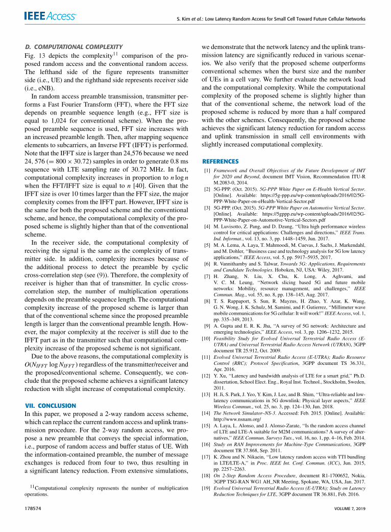
D. COMPUTATIONAL COMPLEXITYFig. 13 depicts the complexity11 comparison of the pro-posed random access and the conventional random access.The lefthand side of the figure represents transmitterside (i.e., UE) and the righthand side represents receiver side(i.e., eNB).
In random access preamble transmission, transmitter per-forms a Fast Fourier Transform (FFT), where the FFT sizedepends on preamble sequence length (e.g., FFT size isequal to 1,024 for conventional scheme). When the pro-posed preamble sequence is used, FFT size increases withan increased preamble length. Then, after mapping sequenceelements to subcarriers, an Inverse FFT (IFFT) is performed.Note that the IFFT size is larger than 24,576 because we need24, 576 (= 800× 30.72) samples in order to generate 0.8 mssequence with LTE sampling rate of 30.72 MHz. In fact,computational complexity increases in proportion to n log nwhen the FFT/IFFT size is equal to n [40]. Given that theIFFT size is over 10 times larger than the FFT size, the majorcomplexity comes from the IFFT part. However, IFFT size isthe same for both the proposed scheme and the conventionalscheme, and hence, the computational complexity of the pro-posed scheme is slightly higher than that of the conventionalscheme.
In the receiver side, the computational complexity ofreceiving the signal is the same as the complexity of trans-mitter side. In addition, complexity increases because ofthe additional process to detect the preamble by cycliccross-correlation step (see (9)). Therefore, the complexity ofreceiver is higher than that of transmitter. In cyclic cross-correlation step, the number of multiplication operationsdepends on the preamble sequence length. The computationalcomplexity increase of the proposed scheme is larger thanthat of the conventional scheme since the proposed preamblelength is larger than the conventional preamble length. How-ever, the major complexity at the receiver is still due to theIFFT part as in the transmitter such that computational com-plexity increase of the proposed scheme is not significant.
Due to the above reasons, the computational complexity isO(NIFFT logNIFFT ) regardless of the transmitter/receiver andthe proposed/conventional scheme. Consequently, we con-clude that the proposed scheme achieves a significant latencyreduction with slight increase of computational complexity.
VII. CONCLUSIONIn this paper, we proposed a 2-way random access scheme,which can replace the current random access and uplink trans-mission procedure. For the 2-way random access, we pro-pose a new preamble that conveys the special information,i.e., purpose of random access and buffer status of UE. Withthe information-contained preamble, the number of messageexchanges is reduced from four to two, thus resulting ina significant latency reduction. From extensive simulations,
11Computational complexity represents the number of multiplicationoperations.
we demonstrate that the network latency and the uplink trans-mission latency are significantly reduced in various scenar-ios. We also verify that the proposed scheme outperformsconventional schemes when the burst size and the numberof UEs in a cell vary. We further evaluate the network loadand the computational complexity. While the computationalcomplexity of the proposed scheme is slightly higher thanthat of the conventional scheme, the network load of theproposed scheme is reduced by more than a half comparedwith the other schemes. Consequently, the proposed schemeachieves the significant latency reduction for random accessand uplink transmission in small cell environments withslightly increased computational complexity.
REFERENCES[1] Framework and Overall Objectives of the Future Development of IMT
for 2020 and Beyond, document IMT Vision, Recommendation ITU-RM.2083-0, 2014.
[2] 5G-PPP. (Oct. 2015). 5G-PPP White Paper on E-Health Vertical Sector.[Online]. Available: https://5g-ppp.eu/wp-content/uploads/2016/02/5G-PPP-White-Paper-on-eHealth-Vertical-Sector.pdf
[3] 5G-PPP. (Oct. 2015). 5G-PPP White Paper on Automotive Vertical Sector.[Online]. Available: https://5gppp.eu/wp-content/uploads/2016/02/5G-PPP-White-Paper-on-Automotive-Vertical-Sectors.pdf
[4] M. Luvisotto, Z. Pang, and D. Dzung, ‘‘Ultra high performance wirelesscontrol for critical applications: Challenges and directions,’’ IEEE Trans.Ind. Informat., vol. 13, no. 3, pp. 1448–1459, Jun. 2017.
[5] M. A. Lema, A. Laya, T. Mahmoodi, M. Cuevas, J. Sachs, J. Markendahl,andM. Dohler, ‘‘Business case and technology analysis for 5G low latencyapplications,’’ IEEE Access, vol. 5, pp. 5917–5935, 2017.
[6] R. Vannithamby and S. Talwar, Towards 5G: Applications, Requirementsand Candidate Technologies. Hoboken, NJ, USA: Wiley, 2017.
[7] H. Zhang, N. Liu, X. Chu, K. Long, A. Aghvami, andV. C. M. Leung, ‘‘Network slicing based 5G and future mobilenetworks: Mobility, resource management, and challenges,’’ IEEECommun. Mag., vol. 55, no. 8, pp. 138–145, Aug. 2017.
[8] T. S. Rappaport, S. Sun, R. Mayzus, H. Zhao, Y. Azar, K. Wang,G. N. Wong, J. K. Schulz, M. Samimi, and F. Gutierrez, ‘‘Millimeter wavemobile communications for 5G cellular: It will work!’’ IEEEAccess, vol. 1,pp. 335–349, 2013.
[9] A. Gupta and E. R. K. Jha, ‘‘A survey of 5G network: Architecture andemerging technologies,’’ IEEE Access, vol. 3, pp. 1206–1232, 2015.
[10] Feasibility Study for Evolved Universal Terrestrial Radio Access (E-UTRA) and Universal Terrestrial Radio Access Network (UTRAN), 3GPPdocument TR 25.912, Oct. 2009.
[11] Evolved Universal Terrestrial Radio Access (E-UTRA); Radio ResourceControl (RRC); Protocol Specification, 3GPP document TS 36.331,Apr. 2016.
[12] Y. Xu, ‘‘Latency and bandwidth analysis of LTE for a smart grid,’’ Ph.D.dissertation, School Elect. Eng., Royal Inst. Technol., Stockholm, Sweden,2011.
[13] H. Ji, S. Park, J. Yeo, Y. Kim, J. Lee, and B. Shim, ‘‘Ultra-reliable and low-latency communications in 5G downlink: Physical layer aspects,’’ IEEEWireless Commun., vol. 25, no. 3, pp. 124–130, Jun. 2018.
[14] The Network Simulator–NS-3. Accessed: Feb. 2015. [Online]. Available:http://www.nsnam.org/
[15] A. Laya, L. Alonso, and J. Alonso-Zarate, ‘‘Is the random access channelof LTE and LTE-A suitable for M2M communications? A survey of alter-natives,’’ IEEE Commun. Surveys Tuts., vol. 16, no. 1, pp. 4–16, Feb. 2014.
[16] Study on RAN Improvements for Machine-Type Communications, 3GPPdocument TR 37.868, Sep. 2011.
[17] K. Zhou and N. Nikaein, ‘‘Low latency random access with TTI bundlingin LTE/LTE-A,’’ in Proc. IEEE Int. Conf. Commun. (ICC), Jun. 2015,pp. 2257–2263.
[18] On 2-Step Random Access Procedure, document R1-1700652, Nokia,3GPP TSG-RANWG1 AH_NR Meeting, Spokane, WA, USA, Jan. 2017.
[19] Evolved Universal Terrestrial Radio Access (E-UTRA); Study on LatencyReduction Techniques for LTE, 3GPP document TR 36.881, Feb. 2016.
178574 VOLUME 7, 2019

S. Kim et al.: Low Latency Random Access for Small Cell Toward Future Cellular Networks
[20] A. Hoglund, D. P. Van, T. Tirronen, O. Liberg, Y. Sui, and E. A. Yavuz,‘‘3GPP release 15 early data transmission,’’ IEEE Commun. StandardsMag., vol. 2, no. 2, pp. 90–96, Jun. 2018.
[21] K. Au, L. Zhang, H. Nikopour, E. Yi, A. Bayesteh, U. Vilaipornsawai,J. Ma, and P. Zhu, ‘‘Uplink contention based SCMA for 5G radioaccess,’’ in Proc. IEEE Globecom Workshops (GC Wkshps), Dec. 2014,pp. 900–905.
[22] K. S. Kim, D. K. Kim, C.-B. Chae, S. Choi, Y.-C. Ko, J. Kim, Y.-G. Lim,M. Yang, S. Kim, and B. Lim, ‘‘Ultrareliable and low-latency communica-tion techniques for tactile Internet services,’’ Proc. IEEE, vol. 107, no. 2,pp. 376–393, Feb. 2019.
[23] K. Lee, S. Kim, J. Kim, and S. Choi, ‘‘DRaMa: Device-specific repetition-aided multiple access for ultra-reliable and low-latency communication,’’in Proc. IEEE Int. Conf. Commun. (ICC), May 2018, pp. 1–6.
[24] K. J. Choi and K. S. Kim, ‘‘Optimal semi-persistent uplink schedul-ing policy for large-scale antenna systems,’’ IEEE Access, vol. 5,pp. 22902–22915, 2017.
[25] Evolved Universal Terrestrial Radio Access (E-UTRA) and Evolved Uni-versal Terrestrial Radio Access (E-UTRAN); Overall Description; Stage 2,3GPP document TS 36.300, Jan. 2016.
[26] Evolved Universal Terrestrial Radio Access (E-UTRA); Medium AccessControl (MAC) Protocol Specification, 3GPP document TS 36.321,Apr. 2016.
[27] NR; Radio Resource Control (RRC); Protocol Specification, 3GPP docu-ment TS 38.331, Sep. 2017.
[28] J. W. Kang, Y. Whang, B. H. Ko, and K. S. Kim, ‘‘Generalized cross-correlation properties of Chu sequences,’’ IEEE Trans. Inf. Theory, vol. 58,no. 1, pp. 438–444, Jan. 2012.
[29] Evolved Universal Terrestrial Radio Access (E-UTRA); Physical Channelsand Modulation, 3GPP document TS 36.211, Mar. 2016.
[30] S. Sesia, I. Toufik, and M. Baker, LTE-the UMTS Long Term Evolution.Hoboken, NJ, USA: Wiley, 2015.
[31] I. Chih-Lin, S. Han, Z. Xu, Q. Sun, and Z. Pan, ‘‘5G: Rethink mobilecommunications for 2020+,’’ Philos. Trans. Roy. Soc. A, Math., Phys. Eng.Sci., vol. 374, no. 2062, Mar. 2016, Art. no. 20140432.
[32] M. Kamel, W. Hamouda, and A. Youssef, ‘‘Ultra-dense networks: A sur-vey,’’ IEEE Commun. Surveys Tutr., vol. 18, no. 4, pp. 2522–2545, 4thQuart., 2016.
[33] P. Kela, M. Costa, J. Salmi, K. Leppanen, J. Turkka, T. Hiltunen, andM. Hronec, ‘‘A novel radio frame structure for 5G dense outdoor radioaccess networks,’’ in Proc. IEEE 81st Veh. Technol. Conf., May 2015,pp. 1–6.
[34] M. Ding, D. Lopez-Perez, H. Claussen, and M. A. Kaafar, ‘‘On the fun-damental characteristics of ultra-dense small cell networks,’’ IEEE Netw.,vol. 32, no. 3, pp. 92–100, May/Jun. 2018.
[35] Q. Wang, G. Ren, and J. Wu, ‘‘A multiuser detection algorithm for randomaccess procedure with the presence of carrier frequency offsets in LTEsystems,’’ IEEE Trans. Commun., vol. 63, no. 9, pp. 3299–3312, Sep. 2015.
[36] Enhanced Performance Requirement for LTE User Equipment (UE), 3GPPdocument TR 36.829, Dec. 2012.
[37] J. Meinilä, P. Kyösti, T. Jämsä, and L. Hentilä, ‘‘WINNER II channel mod-els,’’ in Radio Technologies and Concepts for IMT-Advanced. Hoboken,NJ, USA: Wiley, 2009, pp. 39–92.
[38] G. Wunder, H. Boche, T. Strohmer, and P. Jung, ‘‘Sparse signal pro-cessing concepts for efficient 5G system design,’’ IEEE Access, vol. 3,pp. 195–208, 2015.
[39] Further Advancements for E-UTRA Physical Layer Aspects, 3GPP docu-ment TR 36.814, Mar. 2010.
[40] F. P. Preparata and D. V. Sarwate, ‘‘Computational complexity ofFourier transforms over finite fields,’’ Math. Comput., vol. 31, no. 139,pp. 740–751, 1977.
SUNDO KIM (S’13) received the B.S. degreefrom the Korea Advanced Institute of Science andTechnology, Daejeon, South Korea. He is cur-rently pursuing the Ph.D. degree with the Depart-ment of Electrical and Computer Engineering,Seoul National University, Seoul, South Korea.His research interests include low latency algo-rithm and protocol design for 5G and 6G.
SEONGWON KIM (S’12–M’18) received theB.S. degree in electrical engineering from thePohang University of Science and Technol-ogy (POSTECH), in 2011, and the M.S. andPh.D. degrees in electrical and computer engi-neering from Seoul National University (SNU),in 2013 and 2017, respectively. He is currently aResearch Engineer with the AI Center, SK Tele-com, Seoul, South Korea. Before joining SK Tele-com, he was a Postdoctoral Researcher with Seoul
National University (SNU), Seoul, from October 2017 to February 2019.He was also a Visiting Research Scholar with the Department of Electri-cal and Computer Engineering, Rice University, USA, from July 2017 toOctober 2017. His current research interests include applied AI, the IoTconnectivity, and next-generation wireless networks.
JUNSEOK KIM (S’14) received the B.S. degree inelectronics and electrical engineering fromChung-Ang University, in 2011. He is currently pursuingthe Ph.D. degree with the Department of Electricaland Computer Engineering, Seoul National Uni-versity. His current research interests include 5Gand beyond 5G mobile communications and self-organizing network (SON).
KITAEK LEE (S’15) received the B.S. degree inelectrical and computer engineering from SeoulNational University, in 2015, where he is currentlypursuing the Ph.D. degree with the Departmentof Electrical and Computer Engineering. His cur-rent research interests include 5G and 6G wirelesscommunication networks and emerging technolo-gies of next-generation cellular systems.
SUNGHYUN CHOI (S’96–M’00–SM’05–F’14)received the B.S. (summa cum laude) and M.S.degrees in electrical engineering from the KoreaAdvanced Institute of Science and Technology(KAIST), in 1992 and 1994, respectively, andthe Ph.D. degree from the Department of Elec-trical Engineering and Computer Science, TheUniversity of Michigan, Ann Arbor, in Septem-ber 1999.
He was a Professor with the Department ofElectrical and Computer Engineering, Seoul National University (SNU),Seoul, South Korea, from September 2002 to August 2019. Before joiningSNU in September 2002, he was with Philips Research USA, BriarcliffManor, NY, USA, as a Senior Member Research Staff for three years. Hewas also a Visiting Associate Professor with the Electrical EngineeringDepartment, Stanford University, USA, from June 2009 to June 2010. He isthe Senior Vice President of the SamsungResearch, Seoul. He is currently theHead of the Center for Next-Generation Communication Research, SamsungResearch, working on the researches for 6G, 5G, and the IoT connectivity. Hehas coauthored over 230 technical articles and a book Broadband WirelessAccess and Local Networks: Mobile WiMAX and WiFi, with B. G. Lee,(Artech House, 2008). He holds over 160 patents, and numerous patentspending.
VOLUME 7, 2019 178575

S. Kim et al.: Low Latency Random Access for Small Cell Toward Future Cellular Networks
Dr. Choi received numerous awards including the Recognition of Ser-vice Award from ACM, in 2005 and 2007, the Outstanding ResearchAward and Best Teaching Award from the College of Engineering, SeoulNational University, in 2006 and 2008, respectively, the IEEK/IEEE JointAward for Young IT Engineer, in 2007, the Presidential Young ScientistAward, in 2008, the Best Paper Award from the IEEE WoWMoM 2008,the Shinyang Scholarship Award, in 2011, and the KICS Dr. Irwin JacobsAward, in 2013. He was a recipient of the Korea Foundation for AdvancedStudies (KFAS) Scholarship and the Korean Government Overseas Schol-arship, from 1997 to 1999 and from 1994 to 1997, respectively. He wasnamed as a Fellow of the IEEE, in 2014, for the contribution to the devel-opment of WLAN protocols. He has served as the General Co-Chair ofthe COMSWARE 2008, the Program Committee Co-Chair of the IEEEDySPAN 2018, ACM Multimedia 2007, and the IEEE WoWMoM 2007.He has also served on program and organization committees of numerousleading wireless and networking conferences, including ACM MobiCom,the IEEE INFOCOM, the IEEE SECON, and the IEEE WoWMoM. He iscurrently serving as a Division Editor of Journal of Communications andNetworks, and served as an Editor of the IEEE TRANSACTIONS ON WIRELESS
COMMUNICATIONS, the IEEE TRANSACTIONS ON MOBILE COMPUTING, the IEEEWireless Communications Magazine, ACM SIGMOBILE Mobile Computingand Communications Review, Computer Networks, and Computer Com-munications. He has served as a Guest Editor for the IEEE JOURNAL ON
SELECTED AREAS IN COMMUNICATIONS, the IEEE WIRELESS COMMUNICATIONS,the IEEE TRANSACTIONS ON COGNITIVE COMMUNICATIONS AND NETWORKING, andACM Wireless Networks. From 2000 to 2007, he was an Active Contributorto the IEEE 802.11 WLAN Working Group.
BYONGHYO SHIM (S’95–M’97–SM’09)received the B.S. and M.S. degrees in control andinstrumentation engineering from Seoul NationalUniversity, South Korea, in 1995 and 1997,respectively, and the M.S. degree in mathematicsand the Ph.D. degree in electrical and computerengineering from the University of Illinois atUrbana–Champaign, IL, USA, in 2004 and 2005,respectively. From 1997 to 2000, he was an Officer(First Lieutenant) and also a fulltime Academic
Instructor with the Department of Electronics Engineering, Korean Air ForceAcademy. From 2005 to 2007, he was a Staff Engineer with Qualcomm, Inc.,San Diego, CA, USA. From 2007 to 2014, he was an Associate Professorwith the School of Information and Communication, Korea University,Seoul. Since 2014, he has been with Seoul National University, where heis currently a Professor with the Department of Electrical and ComputerEngineering. His research interests include wireless communications, sta-tistical signal processing, compressed sensing, and machine learning. Heis an elected member of the Signal Processing for Communications andNetworking Technical Committee of the IEEE Signal Processing Society.He was a recipient of the M. E. Van Valkenburg Research Award fromUniversity of Illinois, in 2005, the Hadong Young Engineer Award from theIEIE, in 2010, the Irwin Jacobs Award from Qualcomm and KICS, in 2016,and the Shinyang Research Award from the Engineering College of SNU,in 2017. He has served as an Associate Editor for the IEEE TRANSACTIONS
ON SIGNAL PROCESSING, the IEEE TRANSACTIONS ON COMMUNICATIONS, the IEEEWIRELESS COMMUNICATIONS LETTERS, and the Journal of Communications andNetworks, and a Guest Editor of the IEEE JOURNAL ON SELECTED AREAS IN
COMMUNICATIONS.
178576 VOLUME 7, 2019