LOW-COST RAPID-RESPONSE EMBEDDED ANTENNA DESIGN...
12
LOW-COST RAPID-RESPONSE EMBEDDED ANTENNA DESIGN FOR US ARMY 60MM MORTARS Item Type text; Proceedings Authors Katulka, G.; Hall, R.; Peregino, P.; Muller, P.; Hundley, N.; McGee, R. Publisher International Foundation for Telemetering Journal International Telemetering Conference Proceedings Rights Copyright © held by the author; distribution rights International Foundation for Telemetering Download date 19/06/2018 09:06:45 Link to Item http://hdl.handle.net/10150/604567
Transcript of LOW-COST RAPID-RESPONSE EMBEDDED ANTENNA DESIGN...

LOW-COST RAPID-RESPONSE EMBEDDEDANTENNA DESIGN FOR US ARMY 60MM MORTARS
Item Type text; Proceedings
Authors Katulka, G.; Hall, R.; Peregino, P.; Muller, P.; Hundley, N.; McGee,R.
Publisher International Foundation for Telemetering
Journal International Telemetering Conference Proceedings
Rights Copyright © held by the author; distribution rights InternationalFoundation for Telemetering
Download date 19/06/2018 09:06:45
Link to Item http://hdl.handle.net/10150/604567
1
LOW-COST RAPID-RESPONSE EMBEDDED ANTENNA
DESIGN FOR US ARMY 60MM MORTARS
G. Katulka, R. Hall, P.Peregino, P. Muller Weapons and Materials Research Directorate, Army Research Laboratory, APG
MD 21005-5066
N. Hundley * Dynamic Sciences Inc., APG MD 21005-5066
R. McGee Data Matrix Solutions, APG MD 21005-5066
Abstract
The Defense Advanced Research Projects Agency (DARPA) and the US Army are engaged in a
high-risk/high-payoff project for the development of precision-guided 60mm mortars for the
benefit of the optically designated attack munition (ODAM). This paper describes the antenna
design and performance characteristics required for a telemetry-based onboard diagnostic
system. Efforts executed at the U.S. Army Research Laboratory, Aberdeen Proving Ground, MD
met our primary objective to demonstrate rapid response low-cost capability for body-mounted
antennas compatible with commercially-available telemetry products. This presentation reviews
the theoretical design and antenna radiation pattern characteristics, tuning process, and returned
in-flight signal strength along the trajectory. Experimental results compared favorably with
theoretical link analyses. Lessons learned, ongoing applications, and future improvements are
also presented.
Key Words
Antenna, embedded, mortar, telemetry
* Co-author is presently with the Johns Hopkins University, Applied Physics Laboratory.
2
Introduction
Theoretical simulations were carried out with a commercially available electromagnetic design
software package, Microstripes from Flowmerics, Inc., [1] to determine the optimal patch
locations within the 60-mm mortar body to achieve the desired radiation pattern having an omni-
directional shape coincident in the plane of the mortar body cross section. A circumferentially
located antenna around the mid-body of the mortar was selected since the forward section of the
mortar was to be modified with guidance hardware to meet other objectives of the program [2].
Thus the forebody could not be used to mount the typical fuze type telemetry antenna. To save
space about the perimeter of the mortar body it was decided to use discrete patches equally
spaced at 90 degree intervals rather than a standard monolithic wrap around style antenna
utilized with many large caliber projectiles of record [3], [4]. While a wrap around antenna
should easily achieve the telemetry link margin and structural robustness for the 60mm mortar it
would also discount the use of large amounts of surface area between the individual radiating
antenna elements that could otherwise be used for additional embedded sensors. Given the
limited size of the 60mm mortar the conservation of surface area is a critical design
consideration. Using standard RF design techniques, an embedded quad-patch was evaluated and
selected for the 60mm mortar. This design was also selected due to its ability to be rapidly
implemented at a relatively low cost. The basic physical construct showing some of the
individual antenna elements mounted on the mortar body is given in the picture of Figure 1. The
estimated material cost for the completed antenna is $38 per individual patch element.
The antenna patches were fabricated from RT Duroid high frequency laminate (RT6010) in the
form of circular microstrip patches. This material is well known for its excellent RF properties
and it is widely used for telemetry antennas [5]. The diagram shows the antenna design modified
to include a small tuning tab used for final resonant frequency tuning of the patches after
mounting on the mortar body. A protective coating formed from two part epoxy (JB Weld) was
used as a radome covering on each of the four antenna elements (Figure 1 shows installed
antenna elements and radome). A miniature threaded RF connector (Coaxial Components Corp.
8M130SLG-1) was utilized to make all final connections from the TM package via flexible
coaxial cable (Belden 1671A miniature RF coaxial cable) to the individual patches. This
connector was selected because its quick-connect, threaded body enabled rapid assembly of the
final instrumentation package thus expediting flight testing schedules.
Coupling of the individual patches forming the quad-antenna array was achieved with a
commercial RF coupler, SDB-4-25, from Mini-Circuits shown in Figure 2. Previous testing with
these devices at ARL had demonstrated suitability for telemetry in the high-g environments of
the 60mm mortar of interest. The coupler’s rated attenuation loss of -7db which was taken into
account in our link analysis at the S-band operating frequency of 2,255.0 MHz, and the isolation
between the coupled ports is a minimum of -22db [6]. The characteristics of an individual
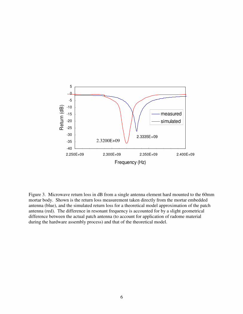
antenna element required of the antenna array are provided in Figure 3 where the microwave
return loss in dB measured with a Hewlett Packard 8753 Network Analyzer is compared to the
simulated value. The measured frequency of the patch is 13.5 MHz higher compared to that of
the simulated patch. This is due to the fact that the patch as measured was slightly altered from
the theoretical model to purposely increase its resonant frequency. This was done to compensate
a resonant frequency drop of about 75 MHz which was observed from the application of radome
3
epoxy material to protect the individual antenna elements in flight. Final tuning of the patches is
accomplished via tuning stub length adjustments made prior to radome epoxy application in
order to achieve 2255MHz. After the quad patch was completely assembled and tuned within
the mortar body, the far field radiation patterns were obtained. These are provided in Figure 4,
showing the roll and the azimuthal or pitch radiation patterns, respectively. All measured
radiation patterns were obtained at 2255 MHz resonant frequency in the anechoic chamber at
ARL, Adelphi, MD.
Structural simulations were carried out using commercial Finite Element Analysis software from
Algor, Inc. [7], to verify the structural integrity of the mortar body modified with embedded
antenna recesses during projectile launch-induced body stresses. Results from these calculations
are provided in Figures 5 and 6. Input assumptions for the structural analysis included two static
g-loading levels of 7,000 and 10,000 g’s and structural survivability was experimentally verified
prior to flight testing via laboratory shock table testing of a prototype 60mm mortar having an
embedded quad-patch antenna.
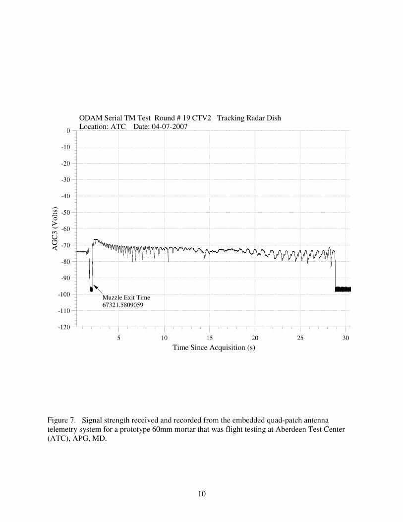
Flight testing was conducted at Aberdeen Test Center (ATC), U.S. Army Aberdeen Proving
Ground, MD. Three prototype mortar rounds were shot to verify the reliability of the telemetry
system (including the patch antenna array as designed) and the quality of the signal strength
received from the mortars. Telemetry data for each of the three rounds were properly received as
illustrated by the receiver AGC data as shown in Figure 7 for mortar round number 19. This plot
shows the receiver signal strength as a function of time from just before mortar launch (marked
as muzzle exit in the plot) to ground impact at 28.6 seconds. The overall signal strength remains
fairly constant through out the mortar flight with anticipated signal undulations or oscillations
coincident with the mortar spin rate. These are caused by the slightly asymmetric radiation
pattern of the embedded antenna array as it spins about the mortar axis.

4
Figure 1. Embedded antenna array shown with packaged telemetry electronics (left), and close
up view of single antenna element with machined radome cover (right).

5
Figure 2. Mini-Circuits RF combiner for integrating individual elements in the quad patch
antenna array used to acquire telemetry during mortar flight testing.
6
Figure 3. Microwave return loss in dB from a single antenna element hard mounted to the 60mm
mortar body. Shown is the return loss measurement taken directly from the mortar embedded
antenna (blue), and the simulated return loss for a theoretical model approximation of the patch
antenna (red). The difference in resonant frequency is accounted for by a slight geometrical
difference between the actual patch antenna (to account for application of radome material
during the hardware assembly process) and that of the theoretical model.
-40
-35
-30
-25
-20
-15
-10
-5
0
5
2.250E+09 2.300E+09 2.350E+09 2.400E+09
Frequency (Hz)
Re
turn
(d
B)
measured
simulated
2.3335E+09
2.3200E+09

7
Figure 4. Experimentally measured radiation patterns for circumferential embedded antenna
array mounted on the 60mm ODAM mortar body. All measurements are made at the S-band
telemetry frequency of 2255.0 MHz inside the ARL anechoic chamber. Patterns are for the
projectile roll (top) and pitch (bottom) orientations.

8
Figure 5. Structural analysis results showing stress levels as a function of safety factor for the
60mm mortar body.
• Load = 7000 g’s

9
Figure 6. Structural analysis results showing stress levels as a function of safety factor for the
60mm mortar body. The highest stress levels observed were concentrated near the region
between antenna patches designed to accommodate solar sensors, thus the machined solar sensor
slots were omitted from the final design.
• Load = 10,000 g’s
10
-120
-110
-100
-90
-80
-70
-60
-50
-40
-30
-20
-10
0
AG
C3
(V
olt
s)
30252015105
Time Since Acquisition (s)
ODAM Serial TM Test Round # 19 CTV2 Tracking Radar DishLocation: ATC Date: 04-07-2007
Muzzle Exit Time
67321.5809059
Figure 7. Signal strength received and recorded from the embedded quad-patch antenna
telemetry system for a prototype 60mm mortar that was flight testing at Aberdeen Test Center
(ATC), APG, MD.

11
Conclusions
The design and performance characteristics of a low-cost antenna array embedded within a
60mm mortar body were described in detail. The antenna is constructed from an array of patch
antenna elements fabricated from standard microwave material and other low cost commercial
components modified to meet the requirements of a compact S-band telemetry system.
Theoretical simulations of the antenna return loss characteristics used during the design phase
were in close agreement with values measured directly from the embedded antenna, and minor
resonant frequency discrepancies were accounted for. The antenna radiation pattern
characteristics and the returned in-flight signal strength along a flight trajectory were also
measured experimentally and demonstrated the viability of our approach as a low-cost, rapid-
response alternative for embedded, high-g, telemetry antenna designs.
Acknowledgments
The authors acknowledge Mr. Barry Bolton from Aberdeen Test Center (ATC) for providing
valuable engineering assistance during the flight testing phases of this effort. Additionally, Mr.
David Hepner (ARL) is acknowledged for valuable technical discussions, suggestions and for
providing motivation in completing this work. Dr. Stephen Weiss (ARL) is acknowledged for
assistance with radiations patterns, and Mr. Thomas Harkins (ARL) is acknowledged for his
thorough technical review of the final manuscript.
Disclaimer
The findings in this report are not to be construed as an official Department of the Army position
unless so designated by other authorized documents, and citations of manufacturer’s or trade
names does not constitute an official endorsement of approval of the use thereof.
References
[1] Microstripes webpage, http://www.flowmerics.com/microstripes/
[2] Hepner, D., ODAM Program, Private Communications.
[3] Condon, J., “Design and Flight Testing of a Mortar Deployed Video Imager”, NDIA
Presentation, April 10, 2001.
[4] Condon, J., Spangler, J., Hepner, D., Harkins, T., “Mechanical and Electrical Design and
Drop Testing of a Munition-Deployed Video Imager,” ARL-TR-2411, 2001.
[5] K. Ryken, Microwave Subsystems, Inc., Oxnard, CA, Private communication, March 13,
2007.
[6] Mini-Circuits data sheet, http://www.minicircuits.com/pdfs/SBD-4-25.pdf
[7] Algor webpage, http://www.algor.com/