Lotus Service Notes Sectionvsic.lotuscars.com/system/files/documents/sn_gk_wheels...
22
Page 1 Lotus Service Notes Section GK WHEELS & TYRES SECTION GK Sub-Section Page General Description GK.1 2 Schrader Type Tyre Pressure Monitoring System (TPMS) GK.2 3 LDL Type Tyre Pressure Monitoring System (TPMS) GK.2a 7 TPMS Fault Finding Procedure GK.2b 12 Wheels GK.3 15 Wheel Bolts GK.4 16 Tyres GK.5 17 Winter Tyres & Snow Chains GK.6 19 Punctured Tyre Emergency Inflators, Spare Wheel & Trolley Jack (GCC Markets Only) GK.7 20 Updated 10 th August 2017
Transcript of Lotus Service Notes Sectionvsic.lotuscars.com/system/files/documents/sn_gk_wheels...

Page 1
Lotus Service Notes Section GK
WHEELS & TYRES
SECTION GK
Sub-Section Page
General Description GK.1 2
Schrader Type Tyre Pressure Monitoring System (TPMS) GK.2 3
LDL Type Tyre Pressure Monitoring System (TPMS) GK.2a 7
TPMS Fault Finding Procedure GK.2b 12
Wheels GK.3 15
Wheel Bolts GK.4 16
Tyres GK.5 17
Winter Tyres & Snow Chains GK.6 19
PuncturedTyreEmergencyInflators,SpareWheel & Trolley Jack (GCC Markets Only) GK.7 20
Updated 10th August 2017

Page 2
Lotus Service Notes Section GK
GK.1 - GENERAL DESCRIPTION
Thesinglepiece,lightalloyorforgedroadwheelsarefactoryfittedwithtyresengineeredtoprovidetheopti-mumbalanceofrideandhandlingcharacteristics.Inorderfullytoexploitthedynamicqualitiesandpackagingopportunities,thewheelandtyresizesaredifferentfrontandrear,sothatinterchangingofwheelsandtyresbetweenaxlesisnotpermissible.Notethatthetyretreadpatternisasymetricacrossthewidth,withtheside-wallsmarked'sidefacinginwards'or'sidefacingoutwards',butthetyremayrotateineitherdirection.
The tyres shouldbe inspected frequentlyby thevehicleuserandalsoatevery service, for signsof cuts,abrasionsorotherdamageandforanyuneventreadwearpatterns.Uneventreadwearmayindicatethatthesuspensiongeometryordampersrequireattention.Careshouldbetakenwhenparkingtoavoidtyrecontactwithhighorsharpedgedkerbs,asmistreatmentofthisnaturecancauseinternaldamagetothetyrestructurewhich may not readily be apparent. The alloy wheel rims may also be distorted or damaged by careless park-ingandresultinwheelimbalanceorlossoftyrepressure.Safetyconsiderationsshouldalwaysbeparamountwhenassessingtyreconditionandserviceabilityandthetyresreplacedifanydoubtexists,orifthelegaltreaddepth limits are approached.
Thecoldtyrepressuresshouldbecheckedeveryweek,orevery1,000miles(1,700km),whicheveristhesoonerandcorrectionsmadeasnecessary.Under‑inflationwillcauseexcessivewear,rapiddeteriorationofthetyresidewallsandheavysteering,whereasover‑inflationresultsinahardrideandincreasedsusceptibilitytotyredamage.Bothconditionswillcauseadegradationinthevehiclehandlingqualities.Itisimportantthatthetyrepressuresareadjustedonlywhenthetyresarecold(drivenlessthanonemile),asthepressuresmayincreaseby0.3‑0.5bar(4‑8lb/in²)whenthetyresarewarmedtonormalrunningtemperature.Thetyrevalvedustcapshouldalwaysbereplacedinordertopreventtheingressofdirtandmoistureintothevalve,whichcould cause leakage.
Whenbalancingthewheelandtyreassemblies,thewheelsshouldbelocatedbythecentrespigot‑NOTbythewheelboltholes.Inordertomaintainthecorrecthandlingfeelandminimumsteeringwheelshake,itisveryimportantthattheradialandlateralrunoutofthetyresaretothehighstandardrequiredbyLotusCars.Ifanydifficultyisexperiencedwithreplacementtyres,refertothetyremanufacturer.
Exige S & Exige Sport 350 ModelsThePirelliP‑ZeroCorsatyresfittedaspartofthe'Sport'packoptionaresuitableforallnormalweathercondi-tions.Thetyrecharacteristicsincludegoodfeedback(‘feel’)fromtheroadsurfacetothesteeringwheel,ahighlevelofsteeringlinearityandresponse,andlittleperformancedegradationwiththehightemperatureswhichmay be reached in sports use.
Althoughapprovedforroaduse,thePirelliP‑ZeroCorsaTrofeotyres*fittedaspartofthe‘Race’packoptionareprimarilydesignedforracetrackdriving.Intheeventofwetroadconditionswiththeriskofaquaplaning,prudentdrivingatareducedroadspeedisrecommended.
*Note:AvailableasadealeroptiononlyafterOctober2014.
Tyreperformancewilldecreaseatlowambienttemperatures,resultinginreducedlevelsofgripandanincreasedsusceptibilitytodamagefromimpacts.Intheseconditions,especiallybelow‑7°C,itisrecommendedtofitacarsetoftherecommendedwintertyres,seesub‑sectionGK.6forfurtherinformation.
Exige Sport 380 ModelsMichelin® Pilot®SportCup2tyresarefittedasstandard,theseareatracktyre(semislicktyre)optimizedforDRYroaduse,however,thistyremeetsthelegalrequirementsforuseonthepublichighwayandopenroadsofthe countries where it is distributed. This tyre passes all the necessary rules and regulations and legal markings.
Thistyrehasbeenspecificallyoptimizedforuseindrytrackconditions,therefore,onawetroad,thereisariskofaquaplaning,whichisacommonriskwithallwidesporttyresandespeciallyasthetyretreadbeginstowearout.Undertheseconditionsroadspeedshouldbereducedandthesafetyanddriverassistancesystems(i.e.‘Tour’mode)shouldbeselected.
Updated 2nd February 2017

Page 3
Lotus Service Notes Section GK
GK.2‑SCHRADERTYPETYREPRESSUREMONITORINGSYSTEM(TPMS) - (Where fitted)
(Pre-17MY and excluding Exige Sport 380 models)
Atyrepressuremonitoringsystem(TPMS)maybefitteddependantonthemarketthevehicleisbuiltfor.Asen-sorfittedintoeachofthetyrevalvesmonitorstheairpressureinsidethetyre,andsuppliesanonboardcontrolmodulelocatedwithinthelefthandwheelarchareaoftherearclamshellwiththisdatabyradiotransmission.Ifanytyrepressureshouldfallbelow75%oftherecommendedvalue,analertmessageissenttotheinstru-ment panel and the tyre pressure tell tale will illuminate amber.
Thefuelgaugedisplaywillthenbeoverwrittenwithamessagetoindicatewhichtyreisconcerned,withtextsuchas:LFLow(lefthandfronttyrelowpressure).Thismessagewillshowfor5secondsbeforethedisplayrevertstothefuellevelbargraph,butwillrepeatfor5secondsat30secondintervals.
TheTPMSincorporatesself‑malfunctionrecognition,andifafaultisdetected,thetelltalewillflashforoneminuteandthenremainconstantlylit.TheLCDpanelwillalsoflash‘TPMSFAULT’for5seconds,andrepeatat30secondintervals;noindicationoflowtyrepressurewillbedisplayed.
TyrefittersandservicetechniciansshouldbemadeawarethatTPMSisfitted,andthatthetyrevalvesincludepressuresensors.Iftheemergencytyreinflatoraerosolhasbeenused,itwillbenecessarytorenewthetyrevalve/pressuresensor.Ifafaultisindicatedafterwheelortyrereplacement,itislikelythatasensorhasbeenincorrectlyfittedordamaged.Ifatyrevalveisrenewed,orismovedtoadifferentwheelposition,theTPMSwillautomaticallyidentifythenewconfiguration.
Notethatthepressuresensorsarepoweredbyintegralbatteries,withanaverageservicelifeof10years.Itisrecommendedtorenewallpressuresensorsatthistimeinterval.
Ifrenewingawheel,ensurethatonlyaLotusTPMScompatiblewheelsuitableforthevehicleisused,astheinstallationangleofthetyrevalveismodifiedtoaccommodatethepressuresensor.Compatiblecastwheelsareidentifiedby'TPMS'withinoneoftherecessesinthehubmountingface.OnTPMScompatibleforgedwheels,theprofileofthewheelrimoutboardofthecentralwell,ismodifiedinordertoallowlocalmachiningaroundthevalveholeontheinsideoftherimtoprovideashallowerinstallationangle.Ifnomachiningisevi-dent,thewheelisnotTPMScompatible.Inaddition,abatchcodeisengravedontotheinnerrimintheformof'PS123456'.Thefirstthreenumbersindicatetheweekandyearofmanufacture,andanywheelwithacodeofPS267###(week26of2007)orlater,willbeTPMScompatible.
TPMStypewheelsmaybefittedonallcars.
Updated 2nd February 2017
LF LOW
LO
TU
S
LO
TU
S
TPMS module TPMS instrument display
TPMS transmitter
Page 4
Lotus Service Notes Section GK
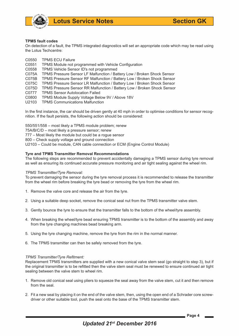
TPMS fault codesOndetectionofafault,theTPMSintegrateddiagnosticswillsetanappropriatecodewhichmaybereadusingtheLotusTechcentre:
C0550 TPMSECUFailureC0551 TPMSModulenotprogrammedwithVehicleConfigurationC0558 TPMS Vehicle Sensor ID's not programmedC075A TPMSPressureSensorLFMalfunction/BatteryLow/BrokenShockSensorC075B TPMSPressureSensorRFMalfunction/BatteryLow/BrokenShockSensorC075C TPMSPressureSensorLRMalfunction/BatteryLow/BrokenShockSensorC075D TPMSPressureSensorRRMalfunction/BatteryLow/BrokenShockSensorC0777 TPMS Sensor Autolocation FailedC0800 TPMSModuleSupplyVoltageBelow9V/Above18VU2103 TPMSCommunicationsMalfunction Inthefirstinstance,thecarshouldbedrivengentlyat40mphinordertooptimiseconditionsforsensorrecog-nition.Ifthefaultpersists,thefollowingactionshouldbeconsidered:
550/551/558–mostlikelyaTPMSmoduleproblem;renew75A/B/C/D–mostlikelyapressuresensor;renew777 – Most likely the module but could be a rogue sensor800–ChecksupplyvoltageandgroundconnectionU2103–Couldbemodule,CANcableconnectionorECM(EngineControlModule)
Tyre and TPMS Transmitter Removal RecommendationsThefollowingstepsarerecommendedtopreventaccidentallydamagingaTPMSsensorduringtyreremovalas well as ensuring its continued accurate pressure monitoring and air tight sealing against the wheel rim.
TPMS Transmitter/Tyre Removal:Topreventdamagingthesensorduringthetyreremovalprocessitisrecommendedtoreleasethetransmitterfromthewheelrimbeforebreakingthetyrebeadorremovingthetyrefromthewheelrim.
1. Removethevalvecoreandreleasetheairfromthetyre.
2. Usingasuitabledeepsocket,removetheconicalsealnutfromtheTPMStransmittervalvestem.
3. Gentlybouncethetyretoensurethatthetransmitterfallstothebottomofthewheel/tyreassembly.
4. Whenbreakingthewheel/tyrebeadensuringTPMStransmitteristothebottomoftheassemblyandawayfromthetyrechangingmachinesbeadbreakingarm.
5. Usingthetyrechangingmachine,removethetyrefromtheriminthenormalmanner.
6. TheTPMStransmittercanthenbesafelyremovedfromthetyre.
TPMS Transmitter/Tyre Refitment:ReplacementTPMStransmittersaresuppliedwithanewconicalvalvestemseal(gostraighttostep3),butiftheoriginaltransmitteristoberefittedthenthevalvestemsealmustberenewedtoensurecontinuedairtightsealingbetweenthevalvestemtowheelrim.
1. Removeoldconicalsealusingplierstosqueezethesealawayfromthevalvestem,cutitandthenremovefromtheseal.
2. Fitanewsealbyplacingitontheendofthevalvestem,then,usingtheopenendofaSchradercorescrew-driverorothersuitabletool,pushthesealontothebaseoftheTPMStransmitterstem.
Updated 21st December 2016

Page 5
Lotus Service Notes Section GK
3. Fromtheinsideofthewheelrim,placethetransmittervalveintowheelrimvalvehole.
4. Placeonesideoftheseal(topsideofthetransmittercaseasseenfromabove)incontactwiththevalvehole.
5. Pushtherearofthetransmittercasetotwistthesealintothevalvehole.The seal will snap into the hole when it is correctly position.
6. Fittheconicalsealhutontothevalvestemthreadandtightenuntil ittouches the wheel rim.
7. Holdingtherearofthetransmittercaseandusingasuitabledeepsockettightentheconicalsealnut(torque7.5Nm).
Note: to ensure that the conical nut istorquedcorrectlysoproducinganairtightseal between the valve stemandwheelrimitisessentialnottopushontopofthetransmittercarsorliftitupwhilsttighteningtheconicalvalvenut.
Stemseal
Wheelrim

Page 6
Lotus Service Notes Section GK
Whenrefittingthetyreonthewheelrim,ensurethatthetransmitterisplacedaheadofthebeadfitmentarmtopreventpotentiallydamagingthetransmittercaseduringrefitment.
Valve Core ReplacementIfreplacingthevalvecoreensurethatonlyanelectrolessnickelplatedcoreisfitted.Usingaplainbrasscoremaycausegalvaniccorrosionoccurringbetweenthecoreandthealuminiumvalvestemcausingeventuallossoftyrepressure.
Valve Cap ReplacementONLY PLASTIC VALVE CAPSshouldbefittedtoaTPMStyrevalve.Thefitmentofametalcapmaycausegalvaniccorrosionbetweenthemetalcapandthestemofthealuminiumvalve.TheresultingdamagecausedtothevalvewhilsttryingtoremovethecorrodedcapcouldalsocauseaTPMSsystemfailure.
Updated 21st December 2016
Page 7
Lotus Service Notes Section GK
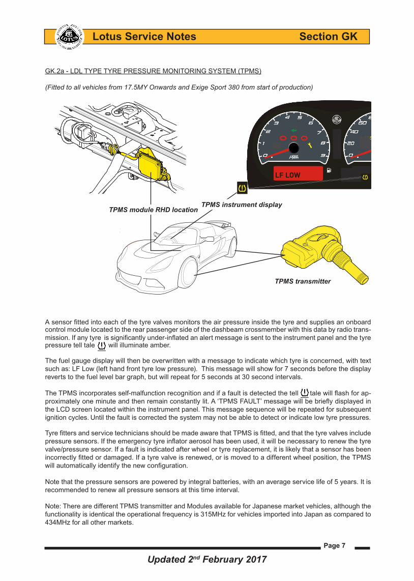
GK.2a‑LDLTYPETYREPRESSUREMONITORINGSYSTEM(TPMS)
(Fitted to all vehicles from 17.5MY Onwards and Exige Sport 380 from start of production)
Asensorfittedintoeachofthetyrevalvesmonitorstheairpressureinsidethetyreandsuppliesanonboardcontrolmodulelocatedtotherearpassengersideofthedashbeamcrossmemberwiththisdatabyradiotrans-mission.Ifanytyre issignificantlyunder‑inflated an alert message is sent to the instrument panel and the tyre pressure tell tale will illuminate amber.
Thefuelgaugedisplaywillthenbeoverwrittenwithamessagetoindicatewhichtyreisconcerned,withtextsuchas:LFLow(lefthandfronttyrelowpressure).Thismessagewillshowfor7secondsbeforethedisplayrevertstothefuellevelbargraph,butwillrepeatfor5secondsat30secondintervals.
TheTPMSincorporatesself‑malfunctionrecognitionandifafaultisdetectedthetelltalewillflashforap-proximatelyoneminuteandthenremainconstantlylit.A‘TPMSFAULT’messagewillbebrieflydisplayedintheLCDscreenlocatedwithintheinstrumentpanel.Thismessagesequencewillberepeatedforsubsequentignition cycles. Untilthefaultiscorrectedthesystemmaynotbeabletodetectorindicatelowtyrepressures.
TyrefittersandservicetechniciansshouldbemadeawarethatTPMSisfitted,andthatthetyrevalvesincludepressuresensors.Iftheemergencytyreinflatoraerosolhasbeenused,itwillbenecessarytorenewthetyrevalve/pressuresensor.Ifafaultisindicatedafterwheelortyrereplacement,itislikelythatasensorhasbeenincorrectlyfittedordamaged.Ifatyrevalveisrenewed,orismovedtoadifferentwheelposition,theTPMSwillautomaticallyidentifythenewconfiguration.
Notethatthepressuresensorsarepoweredbyintegralbatteries,withanaverageservicelifeof5years.Itisrecommendedtorenewallpressuresensorsatthistimeinterval.
Note:TherearedifferentTPMStransmitterandModulesavailableforJapanesemarketvehicles,althoughthefunctionalityisidenticaltheoperationalfrequencyis315MHzforvehiclesimportedintoJapanascomparedto434MHzforallothermarkets.
LF LOW
TPMS transmitter
SPORT120
SPORT120
TPMS instrument display
Updated 2nd February 2017
TPMS module RHD location

Page 8
Lotus Service Notes Section GK
TPMS fault codesOndetectionofafault,theTPMSintegrateddiagnosticswillsetanappropriatecodewhichmaybereadusingtheLotusTechcentre:
B2001 Supplyvoltage‑CircuitvoltagebelowthresholdC0550 TPMSECURAMFailure/HasMalfunctionedC0551 TPMSModulenotprogrammedwithVehicleConfigurationC0558 TPMS Vehicle Sensor ID's not programmedC075A TPMSPressureSensorLFMalfunctionC075B TPMSPressureSensorRFMalfunctionC075C TPMSPressureSensorLRMalfunctionC075D TPMSPressureSensorRRMalfunctionC0777 TPMS Sensor Autolocation FailedC0800 TPMS Module Supply Voltage Below 9VC1300 LostcommunicationwithTirepressuresensormodule‑FrontleftwheelC1303 Lost communication with Tire pressure sensor module - Front right wheelC1304 LostcommunicationwithTirepressuresensormodule‑RearleftwheelC1307 Lost communication with Tire pressure sensor module - Rear right wheelU0001 HighspeedCANcommunicationBus‑BusoffU0127 LostComminucationwithTyrePressureMonitorModuleU2103 TPMSCommunicationsMalfunction
550/551/558–mostlikelyaTPMSmoduleproblem;renew75A/B/C/D–mostlikelyapressuresensor;renew777 – Most likely the module but could be a rogue sensor800–ChecksupplyvoltageandgroundconnectionU2103–Couldbemodule,CANcableconnectionorECM(EngineControlModule)
Refertosub‑sectionGK.2bforbasicTPMSfaultfindinginformation.
TPMS transmitter/valve TheTPMStransmitter/valveassemblycomprisesofthefollowingcomponents:
A. Transmittertovalvescrew*.
B. TPMS transmitter. C. Aluminiumvalvewitharimsealandeitherashortnickelorbrass
coremechanism*. D. Aluminiumnutincorporatingaplasticwasher*.
E. Plasticvalvecap*.
*Theassemblyissuppliedastwoseparateservicelevelparts,thevalve(itemA&C‑E)andthetrans-mitter module (item B).
A
B
C
D
E
Updated 10th August 2017

Page 9
Lotus Service Notes Section GK
Assembling the Transmitter/Valve Assembly1. Removethetransmittertovalvescrew,thealuminiumnutandplasticvalvecap(A,D&E)fromthevalvestem.
2. Fitthetransmittertovalvescrewintothebackofthetransmitterhous-ing(B)ensuringthesquareneckofthescrewispositivelylocatedintothecorrespondingsquareapertureinthehousing.
3. Windthevalvestem(C)ontotheprotrudingthreadofthevalvescrew,thebaseofthevalveshouldfitintothesphericalbaseofthetransmit-terhousing.(Thevalveshouldonlybescrewedinmanuallyandonlytightenedsufficientlysothatthevalvecanswivelwithinthehousingusing light hand pressure).
Ifatyrevalve/sensorisrenewed,orismovedtoadifferentwheelposition,theTPMSwillautomaticallyidentifythenewconfigurationbyinterpretingsignalstrengthasdistancefromsensortoreceiver.
Notethatthepressuresensorsarepoweredbyintegralbatteries,withanaverageservicelifeof5years.Itisrecommendedtorenewallpressuresensorsatthistimeinterval.
Tyre and TPMS Transmitter Removal RecommendationsThefollowingstepsarerecommendedtopreventaccidentallydamagingaTPMSsensorduringtyreremovalas well as ensuring its continued accurate pressure monitoring and air tight sealing against the wheel rim.
TPMS Transmitter/Tyre Removal:1. RemovethecorefromthevalveIfthetyreisstillinflatedorpartiallypressurised(ifithastobereplacedthenitmustbeanewshortcoreofthesametype7442ISOstandard.fitmentofbrassmaterialcoreisforbidden).
2. Beforedetachingthetyrefromtherim,makesurethatthetransmitterisstillcorrectlymountedandtightenedonthewheelrimbycheckingthatthevalvenutistight.
3. Usingasuitabletyrechangingmachine,detachtheinnerandoutertyresidewallbeadsindiametricallyop-positepositionstothetransmitter/valveassembly.
4. Continuetodetachthetyresidewallsbutdonotusemechanical/pneumaticbeadbreakerwithinazoneof20°oneithersideofthetransmitter/valveassembly.
5. Beforeplacingthetyrebeadremoval/fitmentadaptortoolbetweenthetyreandthewheelrim,makesurethatbothsidewallsofthetyrearecompletelydetachedfromthewheelrim.
6. Ensurethattheinnerandoutersidewallsarecompletelydetachedfromthewheelrimbeforeclampingthetyre/wheel assembly onto the tyre changing tool.
7. Placethetyrechangersremoval/fitmentadaptortool20°afterthevalve,(donotplaceanyothertoolsorbarsbetweentheshoeandthevalve,butonlybeyondtheremovalshoe).
8. Startremovingthetyrefromthewheelrimwhilstmaintainingthebeadoftheoppositesidewallonthebot-tomofthebeadseat.
9. Continuetheremovalproceduremovingthetyreawayfromthetransmitter/valveassemblywithoutchangingthedirectionofrotationofthetyrechangersremoval/fitmentadaptortooluntiltheoutersidewalliscompletelyremovedfromthewheelrim.
10. Repeatthisprocedurefortheinnertyresidewall.
11. Unwindandremovethevalvenutfromthevalvestemwithdrawtheassemblyfromtheinnersideofthewheel rim.
2
3
Updated 2nd February 2017

Page 10
Lotus Service Notes Section GK
Fitting a Transmitter/Valve Assembly1. Beforepassingthevalvestemthroughthewheelrimvalvehole,ensurethebaseofthetransmitterisfacingtowardsthewheelrimwiththesmallholeforpressuremeasurementfacingupwardstowardsthetyre.
2. Positionthetransmitter/valveassemblyintopositionen-suringthevalvestemsealingringisstillpartiallyinsidethevalvehole(inordertoavoiditbeingpinchedduringtightening).
3. Refitthealuminiumnutontothevalvestem,screwinginmanuallyatthisstagewhilstapplyingfingerpressuretothe transmitter housing to ensure that it pressed against thevalveholeanditsbaseistouchingthesurfaceofthewheel rim.
4. Continuetotightenapplyingsufficientfingerpressuretoholdthetransmitterhousingagainstthewheelrim,oncetheplasticcollarof theretainingnuttouchesthevalveseatuseasuitablehandoperatedtorquewrench tofinish tighteninguntilafinal torqueof4Nm+/- 0.5
Ensurethetwomountingfeetofthetransmitterarestillcon-tactingthewheelrimoncethevalvenuthasbeentightened.
Tyre FitmentPreparation: Ensurethatthetransmitter/valveassemblyhasbeencorrectlymountedandtightenedbeforefittingthetyreontothewheelrimas shown on the right hand lower illustrations.
Care Points- Ensure that NO tyre lubrication products such astyresoapetcpartiallyorcompletelycoverthepressuremeasuringholeortheinflationholeofthewheel unit.
- The tyre must not come into contact with the trans-mitterduringfitment.
- Ensure that the tyre does not get trapped between the wheel rim and the transmitter.
Valve stem seal
Light finger pressure
Aluminium nut
Light finger pressure
Plastic collar section of aluminium nut contacting wheel rim valve seat
11mm socket and suitable torque wrench used to tighten nut to 4 Nm+/- 0.5
Transmitter housing feet contacting wheel rim
Aluminium retainingnut torqued and contact valve seal
Updated 2nd February 2017

Page 11
Lotus Service Notes Section GK
Tyre FittingCare point: Donotfitthetyrechangersremoval/fitmenttoolbetweenthetyrebeadandtransmitter/valveassembly.- Withthewheelrimfittedonthetyrefittingtool,placethebeadofthetireonthewheelrimapproximately20°beyondthevalve,ensuringthedirectionofrotationofthetyremachinewhenoperatingismovingawayfromthevalve.
- Ensurenottoputanypressureonthetransmitter/valveassemblyduringthisoperation.- Ensure that the refitment/removaladaptor tool iswithdrawn fromthewheel rimbefore itapproaches thetransmitter/valveassembly.
Tyre InflationNoconstraint,eitherfromthetyreorfromtheinflationsystem,shouldbetransmittedtothetransmitterunitduringinflation.
Valve Core ReplacementIfreplacingthevalvecoreensurethatonlyanelectrolessnickelplatedcoreisfitted.Usingaplainbrasscoremaycausegalvaniccorrosionoccurringbetweenthecoreandthealuminiumvalvestemcausingeventuallossoftyrepressure.
Valve Cap ReplacementOnlyplasticvalvecapsshouldbefittedtoaTPMStyrevalve.Thefitmentofametalcapmaycausegalvaniccorrosionbetweenthemetalcapandthestemofthealuminiumvalve.TheresultingdamagecausedtothevalvewhilsttryingtoremovethecorrodedcapcouldalsocauseaTPMSsystemfailure.
TPMS Sensor or Module ConigurationAfterthefitmentofanewTPMSmoduleorsensor(forreasonssuchastyrerenewaletc),the tell tale warn-ing light will initially be illuminated.
Configuration ProcedureAfterthefitmentofanewTPMSmoduleorsensor:
- Drivethevehicleforatimeperiodofbetween4‑10minutesatroadspeedsofbetween15to44mph(25km/h - 70 km/h).
- Thevehicledoesnothavetobemovingconstantlyduringthisprocess,butonlycontinuousdrivingperiodsof60secondsormorewithinthisspeedrangewillallowtheTPMSsensortobesuccessfullyconfigured.
- Theignitioncannotbeturnedoffuntilconfigurationhasbeensuccessfullycompleted.Turningofftheignitionpriortothiswillresultintheconfigurationprocedurehavingtoberepeated.
- OncetheTPMSsensorissuccessfullyconfiguredthetelltalelightwillextinguish.
Updated 2nd February 2017

Page 12
Lotus Service Notes Section GK
GK.2b - TPMSFAULTFINDINGPROCEDURE
AbasicprocessofeliminationcanbeusedtoinitiallydeterminethecauseofaTPMSwarningdisplayandtelltale illumination.
Message: Tell tale:Display in instrument panel Illumination
Theabovedisplayindicatesthatatyrehasfallenbelowthe80%pressurevaluethreshold.Inflatetheaffectedtyretothecorrectpressure,ifthewarningsautomaticallyextinguishwhenthecorrectpressureisrestored,thenthesystemisfunctioningcorrectlyandnofurtherinvestigationisnecessary.
Message: Tell tale:Display in instrument panel Illumination
TheabovedisplayindicatesamalfunctionwithintheTyrePressureMonitoringSystem.
TPMS malfunction fault finding procedure:
Thefollowingimagesandtextareprovidedtosupportthefaultfindingflowchartwhichisincludedwithinthissub-section.
ConnectthevehicletoLotusTechCentre,frommainmenuscreenselectthe'VINRead'optionandthevehicledetails should be displayed
Fromthemainmenu,select:'TPMS (Tyre Pressure Monitoring)'
Rear Wheels & Wheel BoltsThe ‘Offset’ of the rear wheels fitted to the Exige Cup 380 is decreased as compared to those fitted on other Exige models and the rear wheel bolts are increased in length to ensure full thread engagement. Refer to the ‘Technical Data section at the end of this supplement for further wheel and wheel bolt information. Exige Cup 380 rear wheels should NOT be fitted to any other Exige models,
Exige Cup 380 rear wheels should only be fitted to Cup 380 models using the specific wheel bolts supplied with the vehicle.
Wheels - The ‘Offset’of therearwheelsfittedto theExigeCup380 isdecreasedascomparedtothosefittedonotherExigemodels(10Jx18ET32). The rear wheel bolts areincreasedinoveralllengthto57mm(partnumberA138G6012F)toensurefullthreadengagement.ExigeCup380rearwheelsshouldNOTbefittedtoanyotherExigemodels.
Type - Lightweight 10 spoke forged alloy
Size - front 7.5J x 17 ET26 - rear 10J x 18 ET32*
*Fitted to Exige Cup 380 models only
Wheel boltsTorque: 105 Nm (77 lbf.ft)Total overall length: 57mmLotus part number: A138G6012F
TPMS FAULT
Flashing for 1 minute then permantely illuminated
LR LOW
Message displayed, overriding standard screen display or 7 seconds before the display reverts to the fuel level bar graph, but will repeat for 5 seconds at 30 second intervals.
Flashing
Message displayed, overriding standard screen display or 7 seconds before the display reverts to the fuel level bar graph, but will repeat for 5 seconds at 30 second intervals.
Copy files should be maintained by:
Service Manager Service Reception Lotus Technicians Parts Manager
Date: 12.06.2017 Model: Non_Federal 400 Manual TransmissionModels from Start of '17 Model Year to
'17 Model Year VIN SCCLMDVU7HHC11120
Number: 2017/09 Non-USA Markets
CARS
[Text here].
[Next para spacing]
Yours sincerely / Kind regards, (Delete as appropriate)
[Name] – [Title]LOTUS CARS LIMITEDT +44 (0)1953 [######] M +44 (0)[#### ######] [name]@lotuscars.com
[Text here].
[Next para spacing]
Yours sincerely / Kind regards, (Delete as appropriate)
[Name] – [Title]LOTUS CARS LIMITEDT +44 (0)1953 [######] M +44 (0)[#### ######] [name]@lotuscars.com
CLASS 4
TITLE:Ensuring the variant code is applicable for manual transmission Evora 400 models using Lotus Tech-centre.
REASON:To provide owners in all markets with the benefits of the manual transmission oil cooling system, (which was originally fitted only to Federal Evora and Sport 410 models), production build was standardized from the beginning of ‘17 model year onwards with the fitment of manual transmission cooling system to all Evora 400 vehicles. Refer to service notes section FR.7 for further information.
Records indicate that there is a possibility that some ‘17MY Non-Federal Evora 400 and Sport 410 models fitted with manual transmission cooling system prior to '17 model year VIN HHC11120 may not operate as intended because this variant code option was not configured at the time of production.
ACTION:Under normal driving conditions cooling pump activation is not required as the transmission oil will not exceed its normal operational temperature range and therefore the owner may not be aware that the system is inoperative.
To check that that the system operates as intended and ensure that there are no airlocks within the cooler circuit, using Lotus TechCentre, the variant code should be inspected and reset as required on any manual Evora 400 and Sport 410 models within the model year/VIN range as stated above.
Procedure1.Connect the vehicle to Lotus TechCentre, from main menu screen select the the 'VIN Read' option
and the vehicle details should be displayed
2. From the main menu, select 'EMS (Engine Management)'
Continued....
Testing the pump
Return to the “VIN Read” screen using the button shown below:
Read the VIN from the car a second time, and again select “EMS (Engine Management)”.
Select “Actuator Tests”
TPMS (Tyre Pressure Monitoring)TPMS (Tyre Pressure Monitoring)
Updated 10th August 2017

Page 13
Lotus Service Notes Section GK
From the FAULTCODESoption,savethefaultcodeandfreezeframeinformationaspertheinstructionsshowninTechnicalServiceBulletinTSB2013/11.
Forthisexample,FaultCode'C1304‑Lostcom-municationwithTPMS‑Rearleftwheel'hasbeengenerated.
From the VEHICLE INFORMATION option,checkthatall4wheeltrans-mitterserialnumbersareregisteredintheTPMSECU.
Ifall4serialnumbersareregistered,clearanystoredfaultcodesusingLotusTechCentre,thenswapthewheel/tyreassemblyaroundontotheoppositesideofthevehicleanddrivethevehicleabove9mph(15km/h)forover5minutes.
ifthe'TPMSFault'messageisstilldisplayedandFaultCode C1304 is replaced with C1307 - Lost communica-tionwithTPMS‑Rearrightwheel,thenthisindicatesthatthewheeltransmitterisatfault.
Iftheoriginalfaultcodeisstillgeneratedandthe'TPMSFault'messageisstilldisplayed,thenthisindicatesthattheTPMSECUisatfault.
Ifoneormorewheeltransmitterserialnumbersisnotregis-teredthenperformaTPMSConfigurationProcedure,refertosub‑sectionGK2aforfutherinformation.
ifthe'TPMSFault'messageisnolongerdisplayed,thetelltaleextinguishedandall4transmitterserialnum-bers are displayed,thenclearanystoredfaultcodesusingLotusTechCentreandnofurtheractionisrequired.
Iftheerrormessageisstilldisplayedandthetelltalestillilluminated,thenclearanystoredfaultcodesusingLotusTechCentre,swaptheaffectedwheel/tyreassemblyaroundontotheoppositesideofthevehicleanddrivethevehicleabove9mph(15km/h)forover5minutes.Ifthe'TPMSFault'messageisstilldisplayandtheFaultCodeC1304isreplacedwithC1307‑LostcommunicationwithTPMS‑Rearrightwheel,thenthisindicatesthatthewheeltransmitterisatfault.
Iftheoriginalfaultcodeisstillgeneratedandthe'TPMSFault'messageisstilldisplayed,thenthisindicatesthattheTPMSECUispotentiallyatfault.
Nominal Tyre PressureIntheeventthattheTPMStyrepressurewarningdisplayhasoverriddentheinstrumentpanelscreenandtheTPMStelltaleisilluminated(eventhoughtheactualtyreinflationpressurevalueswhenactuallycheckedarecorrectforthevehicle),thenall4nominaltyrethresholdpressuresshouldbecheckedtoensurethattheyaresettothecorrectpressurevalues.
CARS Bulletin number 2013/011 continuedPage 2
2.
3.
Continued...
Save option Print option Fault causing generation of DTC
From Live Data screen select ‘DTC that caused required freeze frame data storage’ option
Print option
Note: It is not possible to ‘save’ this screen dis-play directly into the TechCentre directory.
Therefore use the laptops ‘screen print’ option and transfer it onto a word document to then save it to the relevant file within:
C:\Documents and Settings\My Username\My Documents\Lotus Service
Save & print options
Wheel Unit Sensor Identifier Front Left 817DCBBEWheel Unit Sensor Identifier Front Right 817DD56F
Wheel Unit Sensor Identifier Rear Left 817B901E
Wheel Unit Sensor Identifier Rear Right 817DD376
Vehicle Information
Wheel Unit Sensor Identifier Front Left 817DCBBEWheel Unit Sensor Identifier Front Right 817DD56F
Wheel Unit Sensor Identifier Rear Left
Wheel Unit Sensor Identifier Rear Right 817DD376
Updated 10th August 2017

Page 14
Lotus Service Notes Section GK
From the main menu, select:'TPMS (Tyre Pressure Monitoring)'
Select Live Data Tab and select all avail-able criteria, press '+' button
Once selected, press ' w' (play) to read setting values.
Check the Nominal Pressure values are correct for the vehicle type and tyre specifi-cation fitted. Note: Only Nominal Pressures should change dependant on model type and tyre specification.
For confirmation on tyre pressures refer to service notes sections TDV.
The Warning & Alert threshold % values should always be as displayed. If in any doubt, per-form a threshold re-set using the GUIDED ROUTINES option.
TPMS Malfunction Fault Finding Process Flow Chart
80.00 %80.00 %80.00 %80.00 %85 degrees200.02 KPa200.02 KPa219.02 KPa219.02 KPa80.00 %80.00 %80.00 %80.00 %
200.02 KPa200.02 KPa219.02 KPa219.02 KPa
Perform a TPMSConfiguration Procedure
End
Is the TPMS Fault message
still displayed?
Indicates a fault within the TPMS ECU
Identify TPMS Fault Codes generated using Lotus TechCentre
Confirm that all 4 wheel transmitter serial numbers are registered in the TPMS ECU.
Yes
Are all 4 serial numbers
displayed?
Clear any historical Fault Codes
No
No
Transfer affected wheel/tyre to the other side of the vehicle
Drive Vehicle above 10 mph (15 km/h) for over 5 minutes
Change the wheel transmitter
Clear any historical Fault Codes
Has the Fault Code changed to the other side of
the vehicle?
No
Yes
Yes
Updated 10th August 2017

Page 15
Lotus Service Notes Section GK
GK.3 - WHEELS
RoadwheelsontheExigeSareLotusstyled,castalloy,5spoke‑splitarrangedinpairs,silverorblackpaintedwithadiamondcutfinish.AttheintroductionofExigeSport350&Sport 380models,anew10spokeforgedwheelineithersatingblackorhighpowersilvercoloursweremadeavailable.AttheintroductionofCup 380 abespokerearwheelwasproducedwithadecreasedoffsettoensurethattheincreasedwidthreartyresdonotcontacttherearsuspension/subframe.Therearwheelboltsareincreasedinoveralllengthto57mm(partnumberA138G6012F)toensurefullthreadengagement.seesub‑sectionsGK.4&GK.5forfutherinformation.
IMPORTANT:ExigeCup380rearwheelsshouldNOTbefittedtoanyotherExigemodels,alsoExigeCup380rearwheelsshouldonlybefittedtoCup380modelsusingthespecificwheelboltssuppliedwiththevehicle.
Technical Data
Road WheelType Size/Inset‑front - rear
Type Size/Inset‑front ‑allmodels ‑rear ‑allexceptCup380 - rear - Cup 380 only Winter Wheel Type Size/Inset‑front - rear PCD (Pitch Circle Diameter) - Front - Rear Wheel bolts - thread - Total length - Total length ‑torque - seat Centre spigot hole diameter Radial run-out at bead seat .Lateral run-out at bead seat .
WeightsRoad wheel - Cast Alloy - Front 7.50 kg - Rear 11.07 kg
Road wheel - Forged 10 Spoke - Front 6.70 kg - Rear 9.07 kg
Winter wheel - Front 9.2 kg - Rear 9.8 kg
Notethattheinsetfigureisthedisplacementofthewheelrimcentrelinerelativetothewheel/hubmountingface.Apositiveinsetindicatesthatthewheelrimcentrelineliesinboardofthewheelmountingface,whereasanegativeinsetmeansthewheelrimcentrelineisoutboardofthemountingface.
Castalloy,5spoke‑splitinpairs,silverorblack,5‑boltfixingwithdia-mondcutmachinefinishonthe5radialspokes7.5Jx17H2ET26.3/+26.0mm9.5Jx18H2ET35/+35.0mm
Forged,10spokeinsatinblackorhighpowersilversilver5‑boltfixingwithdiamondcutmachinefinishonthe5radialspokes7.5Jx17H2ET26/+26.0mm10Jx18H2ET35/+35.0mm10Jx18H2ET32/+35.0mm
Castalloy,12spoke,mattblack5‑boltfixing7.5Jx17ET26.3/+26.0mm8.0Jx18ET14.4/+14.4mm
110.0 ± 0.1 mm114.3 ± 0.1 mmM12x1.553mm(frontandrearwheelboltsallmodelsexceptCup380)57mm(rearforCup380models,butsuitableforallmodels)105 Nm60°taper65 mm0.3mmmax.0.3mmmax.
INSIDE OUTSIDE face of face of wheel wheel
Wheelrim centreline Wheel mounting face
Inset (positive shown) g02
Updated 22nd June 2017

Page 16
Lotus Service Notes Section GK
GK.4 - WHEEL BOLTS
Thewheel bolts usedareof a special design tosuitthesmalldiameterfixingtunnelsinthewheelcentres.TheboltshaveanM12x1.5thread,60°conicalseat,anda10splinesocketheadforwhichaspecialextensiontoolissuppliedwiththecar.
A17mma/fdeepsocketand1/2inchsquaredrivetorquewrenchshouldbeappliedtotheextensiontool,withatighteningtorqueof105Nmrequired.
Wheel BoltsAtthestartofproduction,thefrontandrearwheelbolttotallengthwas53mm.TherearwheelboltsfittedtoCup 380 models are 57 mm in length toensurefullthreadengagementbecauseofthedecreaseinwheeloffsetproducedbytheincreaseinthicknessoftherearwheel hub.
Optional FitmentToprotectagainstwheeltheft,oneofthefiveboltssecuringeachwheeliskeycoded,andrequiresacorre-spondingly coded adaptor tool.
Boththestandardextensionandcodedsockettools(iffitted)arestowedintherear luggagecompartmentwithinthevehicletoolkit,andshouldremainwiththecaratalltimestoensurethatservicingmaybeperformed.
Thekeycodeincludedinthetoolkitshouldberecordedandkeptsafelywiththevehicledocuments,incaseareplacement socket tool needs to be ordered.
Wheel Bolt RemovalFittheadaptortoolontoa1/2inchsquaredriveextension.
Rotatetheadaptoruntilfullengagementintotheboltheadisassuredbeforeapplyingtorque.
Notethatanalignmentmarkisprovidedonthecodedboltheadandadaptortooltoaidrefitting.
Standard wheelbolt
Splined extension tool
Coded adaptor Coded wheelbolt
17mm socket, extension & torque wrench ohs114d
Updated 22nd June 2017

Page 17
Lotus Service Notes Section GK
GK.5 - TYRES
Exige S & Exige Sport 350 (refer to following page for Exige Sport 380 and Exige Cup 380 models)The Pirelli P-Zero Corsa tyres fitted as standard production for the 'Sports' option are suitable for all normal weather conditions. The tyre characteristics include good feedback (‘feel’) from the road surface to the steer-ing wheel, a high level of steering linearity and response, and little performance degradation with the raised temperatures which may be reached in high speed use.
Although approved for road use*, the Pirelli P-Zero Corsa Trofeo tyres fitted as part of the ‘Race’ pack option are primarily designed for racetrack driving. In the event of wet road conditions with the risk of aquaplaning, prudent driving at a reduced road speed is recommended.
*Note: (Available as a dealer option only after October 2014).
Trofeo Tyre FitmentThe different construction of the Trofeo tyre requires an increased inflation pressure to seat the tyre on the Exige S styled rim.
Pirelli has advised a 5.0 bar maximum pressure when using manual mounting methods to seat the Trofeo tyre on the rim.
Note: To ensure technician safety, the wheel/tyre assembly should be position in a cage whilst attempt-ing to seat the tyre on the rim due to the increased pressure requirements.
Tyre performance will decrease at low ambient temperatures, resulting in reduced levels of grip and an increased susceptibility to damage from impacts. In these conditions, especially where average temperatures are below 0°C (32°F), or where snow may be expected, it is recommended to fit a car set of the recommended winter tyres, see sub-section GJ.6 for additional information.
Note that the Pirelli P-Zero tread pattern is asymmetrical, so that when fitting tyres, attention must be paid to the sidewall marking, and the side of the car for which the wheel and tyre is intended.
Wear indicators are moulded into the bottom of the tread grooves at intervals around the tyre, indi-cated by small pointers on the outer tread blocks. The tyres should be replaced before being worn to this minimum legal tread depth.
Tyres Type - std. Pirelli P-Zero Corsa - opt. Pirelli P Zero Trofeo *Note: Available as a dealer option only after October 2014.Size - front 205/45 ZR17 - 88Y - rear 265/35 ZR18 - 97Y (std.) 93Y (opt.)
Standard Pressures (cold) - front - std & opt. 2.2 bar (31.9 lb/in²) - rear - std & opt. 2.6 bar (38 lb/in²)
Economy Pressures (cold)‡Automatic vehicles only - Front - std tyres only 2.6 bar (38.0 lb/in²) - Rear - std tyres only 3.0 bar (43.5 lb/in²)
‡NOTE: Inflating the tyres to the ‘economy’ tyre pressures of 2.6 bar (front) and 3.0 bar (rear) will adversely affect the handling characteristics and the drivers enjoyment of the car. Lotus does not recommend these tyre pressures are used at speeds in excess of 80mph (128kph).
Outboard tread Inboard tread pattern pattern
g23
Updated 22nd June 2017

Page 18
Lotus Service Notes Section GK
Exige Sport & Cup 380 ModelsMichelin® Pilot®SportCup2tyresarefittedasstandard,theseareatracktyre(semislicktyre)optimizedforDRYroaduseaboveambienttemperaturesof7°Centigrade,however,thistyremeetsthelegalrequirementsforuseonthepublichighwayandopenroadsofthecountrieswhereitisdistributed.Thistyrepassesallthenecessary rules and regulations and legal markings.
Thistyrehasbeenspecificallyoptimizedforuseindrytrackconditions,therefore,onawetroad,thereisariskofaquaplaning,whichisacommonriskwithallwidesporttyresandespeciallyasthetyretreadbeginstowearout.Undertheseconditionsroadspeedshouldbereducedandthesafetyanddriverassistancesystems(i.e.‘Tour’mode)shouldbeselected.
SpecificationType - Michelin® Pilot® Sport Cup 2 Size ‑front215/45 R17 - 91Y (Fitted to Sport & Cup 380 models) - rear 265/35 R18 - 97Y (Fitted to Sport 380 models) - rear 285/30 R18‑97Y (FittedtoSport380models)*
Tyre Pressure (cold) Exige Sport & Cup 380 Modelsfront ‑2.0bar(29lb/in²)rear - 2.2 bar (32 lb/in²)
* Rear TyresThewidthofthereartyresfittedtotheExigeCup380isincreasedascomparedtothosefittedonotherExigemodels.Therearwheel‘Offset’,vehiclebodyandspecificrearsuspensionmountingpointshavebeenmodifiedto accommodate the increased width rear tyre.
AttemptingtofittheExigeCup380reartyrestootherExigemodelswillresultinpotentialtyreandbodyworkdamage.
Updated 22nd June 2017
Page 19
Lotus Service Notes Section GK
GK.6‑WINTERWHEELS,TYRES&SNOWCHAINS
Ifthecaristobeusedinverycoldclimates,ordrivenonsnowcoveredroads,itisrecommendedtofitacom-pletevehiclesetofwintertyresdevelopedspecificallyforsuchconditions.FortheExigeS,LotusrecommendstheuseofPirelliSottoZeroSerieIIwintertyresinsizesspecifiedbelowfittedwithbespokewinterwheelsasdescribed in sub-section GK.3.
Wearindicatorsaremouldedintothebottomofthetreadgroovesatintervalsaroundthetyre,indicatedbysmallpointersontheoutertreadblocks.Inorderthatthesetyresmaintaintheirdesignperformanceonsnowcoveredroads,theminimumtreaddepthisdesignatedas4mm,whichisreflectedintheheightofasecondarysetofwearindicators.
Notethatthetreadpatternisasymmetrical,sothatwhenfittingtyres,attentionmustbepaidtothesidewallmarking,andthesideofthecarforwhichthewheelandtyreisintended.
Winter TyresType ‑front Pirelli210SottoZeroSerieII - rear Pirelli 240 SottoZero Serie IISize ‑front 205/45R17‑88VM+S - rear 235/40 R18 - 95V M+SPressure (cold) ‑front 2.3bar(33.5lb/in²) - rear 2.6 bar (36 lb/in²)
WARNING: - When winter tyres are fitted, a maximum speed of 118 mph (190 km/h) must be observed. - The tyres are NOT suitable for studding.
Snow ChainsInextremeweatherconditions,LotusapprovesthefitmentofRUD‑maticClassicR48493snowchainsusedonlyinconjunctionwithwintertyres(seeabove)andfittedonlyontherearwheels.Closeattentionshouldbepaidtothefittingandtensioninginstructionssuppliedwiththechains.Thechainsshouldberemovedassoonas road conditions allow.

Page 20
Lotus Service Notes Section GK
GK.7‑TYREEMERGENCYINFLATORS,(Spare Wheel & Trolley Jack for GCC Markets Only)
Inorderfullytoexploit thebenefitsof lightweight,and tomaximisestowagespace, theExigeShasnoprovisionforsparewheelcarriageorliftingjack.
Atemporarypuncturesealingfacilityisprovidedintheformofanemergencytyreinflatoraerosolmountedinaspringclipattheextremerighthandsideoftheboot. Ifpossible,avoiddrivingonadeflated tyre,or irreparable damage to the tyre structure may be caused.
Whentheaerosolisconnectedtothetyrevalve,andthebuttonpressed,amixtureofliquidlatexandpropel-lantisinjectedintothetyre,suchthatthesolidifyinglatexisforcedintothepuncturesiteatthesametimeasthetyreisinflated,effectingatemporaryrepairandenablingthecartobedrivenatlowspeedtothenearesttyre depot.
WARNING:- Use of the aerosol does not constitute a permanent repair, but is designed to allow the car to be driven
to the nearest tyre depot. At the earliest opportunity, the tyre should be professionally repaired or replaced dependent on the severity of the damage.
- Until the tyre is repaired or replaced, the car should be driven only in a moderate manner, not exceed-ing 30 mph (45 km/h).
- Do not use the aerosol for large holes or repairs, or when the tyre sidewall has been damaged, or if the tyre has been displaced from the rim.
- For safety reasons, the aerosol should be carried at all times in the designated stowage position. Never carry in the passenger compartment.
Assoonasapunctureissuspected,thecarshouldbestoppedatthefirstsafeopportunity.Continueddrivingonadeflatedtyrewillcauseirreparabledamagetothetyre.
Directions for use of the aerosol: Beforeusing,carefullyreadalltheinstructionsonthecanister,oronanyliteratureaccompanyingtheproduct.ThefollowinginstructionsapplytotheuseofHoltsTyreweld:
1. Removetheobjectcausingthepuncture,andpositionthewheelwiththepuncturesitelowermost.Deflatetyrefully.
2. Shakethecanvigorously.Incoldconditions,warmthecanusingthecar'sheateroutlets,orbybodywarmth.
3. Screwtheaerosoltubeontothetyrevalve,removethecap,holdthecanuprightandpressthebuttonuntilthetyreisfirmlyinflated.
4. Immediatelydrivefor6‑12miles(10‑20km)(ortothetyredepotifnearer)inamoderatemannerandnotexceeding30mph(45km/h),toallowthesealanttospread.Thencheckandadjustthetyrepressure.
5. Have the tyreprofessionally repairedor replacedat theearliestopportunity,anduntilsuch time, limitspeedto30mph(45km/h)withamoderatedrivingmanner.Notethatsometyrerepairersmaymakeanadditionalchargeforcleaningthesealantoffthetyrebeforerepair,andthatanysubsequentrepairsmaynot be guaranteed. Be aware that the electronic pressure sensor mounted inside the tyre and integral withthetyrevalve,couldbeobstructedbythesealant,andshouldberenewed.
6. Renewtheemergencyinflatoraerosol.
TYRE INFLATOR AEROSOL
ohs118
Page 21
Lotus Service Notes Section GK
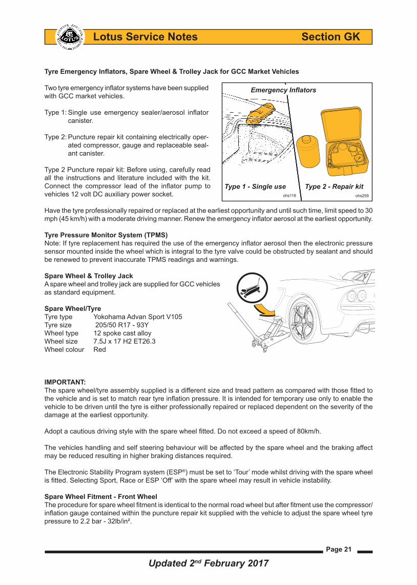
Tyre Emergency Inflators, Spare Wheel & Trolley Jack for GCC Market Vehicles
TwotyreemergencyinflatorsystemshavebeensuppliedwithGCCmarketvehicles.
Type1:
Type2:
Type2Puncturerepairkit:Beforeusing,carefullyreadall the instructions and literature included with the kit. Connect the compressor lead of the inflator pump tovehicles12voltDCauxiliarypowersocket.
Havethetyreprofessionallyrepairedorreplacedattheearliestopportunityanduntilsuchtime,limitspeedto30mph(45km/h)withamoderatedrivingmanner.Renewtheemergencyinflatoraerosolattheearliestopportunity.
Tyre Pressure Monitor System (TPMS)Note:IftyrereplacementhasrequiredtheuseoftheemergencyinflatoraerosolthentheelectronicpressuresensormountedinsidethewheelwhichisintegraltothetyrevalvecouldbeobstructedbysealantandshouldberenewedtopreventinaccurateTPMSreadingsandwarnings.
Spare Wheel & Trolley JackAsparewheelandtrolleyjackaresuppliedforGCCvehiclesasstandardequipment.
Spare Wheel/TyreTyretype YokohamaAdvanSportV105Tyresize 205/50 R17 - 93Y Wheel type 12 spoke cast alloy Wheelsize 7.5Jx17H2ET26.3 Wheel colour Red
IMPORTANT: Thesparewheel/tyreassemblysuppliedisadifferentsizeandtreadpatternascomparedwiththosefittedtothevehicleandissettomatchreartyreinflationpressure.Itisintendedfortemporaryuseonlytoenablethevehicletobedrivenuntilthetyreiseitherprofessionallyrepairedorreplaceddependentontheseverityofthedamage at the earliest opportunity.
Adoptacautiousdrivingstylewiththesparewheelfitted.Donotexceedaspeedof80km/h.
Thevehicleshandlingandselfsteeringbehaviourwillbeaffectedbythesparewheelandthebrakingaffectmaybereducedresultinginhigherbrakingdistancesrequired.
The Electronic Stability Program system (ESP®)mustbesetto‘Tour’modewhilstdrivingwiththesparewheelisfitted.SelectingSport,RaceorESP‘Off’withthesparewheelmayresultinvehicleinstability.
Spare Wheel Fitment - Front WheelTheprocedureforsparewheelfitmentisidenticaltothenormalroadwheelbutafterfitmentuse the compressor/inflationgaugecontainedwithinthepuncturerepairkitsuppliedwiththevehicletoadjustthesparewheeltyrepressure to 2.2 bar - 32lb/in².
ohs118
Emergency Inflators
Type 1 - Single use Type 2 - Repair kitohs259
Single use emergency sealer/aerosol inflatorcanister.
Puncture repair kit containing electrically oper-atedcompressor,gaugeandreplaceableseal-ant canister.
Updated 2nd February 2017

Page 22
Lotus Service Notes Section GK
Spare Wheel Fitment - Rear WheelIMPORTANT:Topreventdamagetothevehicleandtoensurecorrectfitment,thesparewheelhubspacerand30mmspacerboltssuppliedwiththesparewheeltoolkitMUSTbefittedasdescribedwhenusingthesparewheelasatemporaryreplacementinplaceofeitheroftherearwheels.
Failuretofitthesparewheelhubspacerandthelonger30mmwheelboltscouldcausetheboltstocomelooseandthewheeltocomeoff,resultinginacrashinwhichyouandotherscouldbeseriouslyinjuredorkilled.
Procedure:Removetheapplicablerearwheel.
- Position the spare wheel hub spacer supplied inthesparewheeltoolkitontothebossoftherear hub assembly.
- Align the spacers 5 plain recessed bolt holes with the corresponding wheel bolt threads on thevehicle'shubassembly.
- Screw in the 5 spacer bolts (supplied with the spare wheel tool kit) to secure the spacer onto the hub assembly.
- Using a suitable torquewrench, fully tightenall 5 spacer bolts in a crosswise pattern using the wrench and 15mm socket supplied in the spare wheel tool kit. Ensure all 5 spacer bolts aretightenedtoatorqueof105Nm(77.5lbf.ft).Thespacerisnowfullysecuredtotherearhub assembly.
- Positionthesparewheelontothebossof thehubspacer,aligningthe5wheelboltholeswiththe5threadedholesofthespacer.
- Screwinatleast2ofthevehiclewheelboltsatoppositepointstoretainthesparewheelinpositionontothespacer.
- Screwintheremaining3vehiclewheelboltsandthentightenthemallinacrosswisepatternusingawrenchand 17mm socket.
- Followingmanufacturers’instructions,releasethejackandlowerthevehicletotheground.
- Usingasuitabletorquewrench,fullytightenalltheboltstoatorqueof105Nm(77.5lbf.ft).
- Usingthecompressor/inflationgaugecontainedwithinthepuncturerepairkitsuppliedwiththevehicle,adjustthe spare wheel tyre pressure to 2.6 bar (38lb/in²).
IMPORTANT:Adoptacautiousdrivingstylewiththesparewheelfitted.Donotexceedaspeedof80km/h.Thevehicleshandlingandselfsteeringbehaviourwillbeaffectedbythesparewheelandthebrakingaffectmaybereducedresultinginhigherbrakingdistancesrequired.
The Electronic Stability Program system (ESP®)mustbesetto‘Tour’modewhilstdrivingwiththesparewheelisfitted.SelectingSport,RaceorESP‘Off’withthesparewheelmayresultinvehicleinstability.
ohs252
SPARE WHEEL FITMENT (Rear fitment shown)
Sparewheel
Wheelbolt
Hub spacer(rear wheel only)
ohs252Spacerbolt
Updated 2nd February 2017