Catalog : Slipping Through the Cracks - curated by Meera Menezes
description

Power Plant and Transmission System Power Plant and Transmission System Protection CoordinationProtection Coordination
LossLoss--ofof--Field (40) and OutField (40) and Out--ofof--Step Protection (78)Step Protection (78)
System Protection and Control Subcommittee Protection Coordination Workshop
Phoenix, AZMarch 17-18, 2010

2AgendaAgenda
Objectives
Description of Protection Functions
Stability Fundamentals and Examples
Discuss and Describe System Events that Could Create Conditions that Would Cause Operation of These Functions
Seven Step Process for both Functions 40 and 78•
Function 40 –
Loss-of-Field (a.k.a. Loss-of-Excitation)
•
Function 78 –
Out-of-Step

5
The Need for LossThe Need for Loss--ofof--Field Field Protection Protection –– Function 40Function 40
“The source of excitation for a generator may be completely or partially removed through such incidents as accidental tripping of a field breaker, field open circuit, field short circuit (flashover of the slip rings), voltage regulation system failure, or the loss of supply to the excitation system. Whatever the cause, a loss of excitation may present serious operating conditions for both the generator and the system.
When a generator loses its excitation, it overspeeds and operates as an induction generator. It continues to supply some power to the system and receives its excitation from the system in the form of vars.”
IEEE C37.102-2006 –
Guide for AC Generator Protection, Section 4.5.1

6
The Need for LossThe Need for Loss--ofof--Field Field Protection Protection –– Function 40Function 40
Loss of field can occur due to:•
Accidental tripping of a field breaker.
•
Field open circuit or field short circuit (flashover of the slip rings).
•
Voltage regulation system failure, or the loss of supply to the excitation system.

7
The Need for LossThe Need for Loss--ofof--Field Field Protection Protection –– Function 40Function 40
Loss of excitation may present serious operating conditions for both the generator and the system.
Generator effects:•
Generator overspeeds and operates as an induction generator receiving its excitation from the system.
•
Stator currents can exceed 2 pu causing dangerous overheating of the stator winding and core.
•
High levels of slip-frequency currents can be induced in the rotor causing over heating of the rotor.

8
The Need for LossThe Need for Loss--ofof--Field Field Protection Protection –– Function 40Function 40
Power System effects:•
A loss of field condition causes devastating impact on the power system due to loss of reactive power support from the generator.
•
Creates a substantial reactive power drain from the system.
•
On large generators this condition can contribute to or trigger a wide area system voltage collapse

9
The Need for LossThe Need for Loss--ofof--Synchronism Synchronism Protection Protection –– Function 78Function 78
“The protection normally applied in the generator zone, such as differential relaying, time-delay system backup, etc., will not detect loss of synchronism. The loss-of-field relay may provide some degree of protection but cannot be relied on to detect generator loss of synchronism under all system conditions. Therefore, if during a loss of synchronism the electrical center is located in the region from the high-voltage terminals of the GSU transformer down into the generator, separate out-of-step relaying should be provided to protect the machine. This is generally required for larger machines that are connected to EHV systems.
On large machines the swing travels through either the generator or the main transformer. This protection may also be required even if the electrical center is out in the system and the system relaying is slow or cannot detect a loss of synchronism. Transmission line pilot-wire relaying, current- differential relaying, or phase comparison relaying will not detect a loss of synchronism. For generators connected to lower voltage systems, overcurrent relaying may not be sensitive enough to operate on loss of synchronism.”
IEEE C37.102-2006 –
Guide for AC Generator Protection, Section 4.5.3.1

10
During an out-of-step or pole slip condition the voltage magnitude between the generator and the system reaches two per unit (at 180 degrees) which can result in high currents that cause mechanical forces in the generator stator windings and undesired transient shaft torques.
It is possible for the resulting torques to be of sufficient magnitude so that they cause serious damage to the shaft and to the turbine blades.
It can cause excessive overheating and shorting at the ends of the stator core.
It can also cause damaging transient forces in the windings of the GSU transformer as well.
The Need for LossThe Need for Loss--ofof--Synchronism Synchronism Protection Protection –– Function 78Function 78

11
40 78
Relay OneRelay One--Line Showing All Generator Line Showing All Generator Protection and Identifying Function 40 and 78Protection and Identifying Function 40 and 78

12Stability FundamentalsStability Fundamentals
Power System Stability -
“If the oscillatory response of a power system during the transient period following a disturbance is damped and the system settles in a finite time to a new steady operating condition we say the system is stable. If the system is not stable, it is considered unstable.”
Stability is a property of an electrical power system which has two or more synchronous machines. A system is stable for a specific set of conditions if all synchronous machines remain in step with each other. A system can be stable for one set of conditions and unstable for another.
Transient Stability
Swing Equation –
Accelerating Torque Equals Mechanical Torque Minus Electrical Torque
Ta
= Tm
- Te
Newton Meters
Equal Area Criterion

Equal Area Method to Equal Area Method to Determine StabilityDetermine Stability

14Stability Study ExamplesStability Study Examples
Sample apparent impedance swings are presented in this figure for a dual lens characteristic out-of-step relay. In this figure the time interval between markers is 100 ms (6 cycles) such that the faster swings have greater distance between markers. The three traces represent marginally stable and unstable swings for fault clearing at and just beyond the critical clearing time, and a trace for the worst credible contingency representing the fastest unstable swing
Marginally Stable Swing
Marginally Unstable Swing
Worst Case (Fastest) Unstable Swing
Notes:
Time between markers () is 100 msScale is apparent impedance
in secondary ohms
This group of protective functions (Function 40 and 78) needs to be validated against
transient stability studies to insure that tripping does not occur for stable impedance swings.

15
System Events that Could Cause Undesired System Events that Could Cause Undesired Operation of These Protection FunctionsOperation of These Protection Functions
Fault Conditions
Loss of Critical Lines
Loss of Critical Units
Events such as August 14, 2003 Blackout
System Islanding Conditions

16
Seven Step Process for Seven Step Process for both Functions 40 and 78both Functions 40 and 78
This is the process used throughout the coordination Technical Reference Document to address each protective function as appropriate.
The following slides will take a step-by-step approach through both the Function 40 and 78.
The next two slides provide the general data and information requirements from the Generator, Transmission, and Distribution Owners.
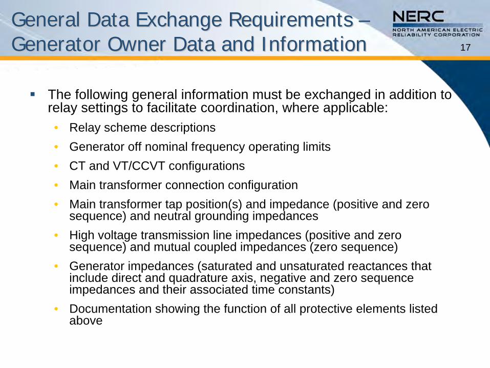
17
General Data Exchange Requirements General Data Exchange Requirements –– Generator Owner Data and InformationGenerator Owner Data and Information
The following general information must be exchanged in addition to relay settings to facilitate coordination, where applicable:•
Relay scheme descriptions•
Generator off nominal frequency operating limits•
CT and VT/CCVT configurations •
Main transformer connection configuration•
Main transformer tap position(s) and impedance (positive and zero sequence) and neutral grounding impedances
•
High voltage transmission line impedances (positive and zero sequence) and mutual coupled impedances (zero sequence)
•
Generator impedances (saturated and unsaturated reactances that include direct and quadrature axis, negative and zero sequence impedances and their associated time constants)
•
Documentation showing the function of all protective elements listed above

18
General Data Exchange Requirements General Data Exchange Requirements –– Transmission or Distribution Owner Data and InformationTransmission or Distribution Owner Data and Information
The following general information must be exchanged in addition to relay settings to facilitate coordination, where applicable:•
Relay scheme descriptions•
Regional Reliability Organization’s off-nominal frequency plan •
CT and VT/CCVT configurations•
Any transformer connection configuration with transformer tap position(s) and impedance (positive and zero sequence) and neutral grounding impedances
•
High voltage transmission line impedances (positive and zero sequence) and mutual coupled impedances (zero sequence)
•
Documentation showing the function of all protective elements•
Results of fault study or short circuit model•
Results of stability study•
Communication-aided schemes

19
Document Format Document Format –– Seven SubSeven Sub--Sections Sections for Each Protection Functionfor Each Protection Function
Purpose
Coordination of Generator and Transmission System•
Faults•
Loadability•
Other Conditions, where applicable
Considerations and Issues
Setting Validation for the coordination•
Test procedure for validation •
Setting Considerations
Examples•
Proper Coordination•
Improper Coordination
Summary of Detailed Data Required for Coordination of the Protection Function
Table of Data and Information that must be Exchanged

20LossLoss--ofof--Field Field –– Function 40Function 40
Purpose•
Detect and prevent unsafe and damaging operation of the generator during loss-of-excitation events.
R
X
Zone-1
Zone-2
Condensing
Heavy Loadpf=0.95Lagging
Light Loadpf=0.99Lagging
MachineCapability
Curve
MinimumExcitation
Limiter
Figure 3.5.1 —
(1) Locus of Swing Impedance during Light & Heavy Loads for LOF, and (2)
Relationship between Minimum Excitation Limiter (MEL) or Under Excitation Limiter (UEL), and a Typical Condensing Operation Area
Loss of Field protection characteristic on the R-X diagram

21
Coordination of Generator and Coordination of Generator and Transmission System Transmission System –– Function 40Function 40
Faults•
Step 1 —
The Transmission Owner provides the Planning Coordinator with the worst case clearing time for each of the power system elements connected to the generator bus.
•
Step 2 —
The Planning Coordinator determines the stability impedance trajectory for the above conditions.
•
Step 3 —
The Planning Coordinator provides these plots to the Generator Owner.
The Generator Owner utilizes these plots to demonstrate that these impedance trajectories coordinate with the time delay setting of the loss-of-field (LOF) relay to prevent misoperations by having adequate time delay.
•
A system stability study may be required to evaluate the generator and system response to power system faults.
The response of the LOF relays under these conditions must be studied to see if they respond to power swing conditions as a result of system faults.
The Transmission Owner, Generator Owner, and Planning Coordinator must share information on these studies and LOF relay settings to prevent inadvertent tripping of generators for external fault conditions not related to a loss-of-field condition.
If there is an out-of-step protection installed it should be coordinated with the LOF protection.

22
Coordination of Generator and Coordination of Generator and Transmission System Transmission System –– Function 40Function 40
Loadability•
Step 1 —
The Generator Owners confirms that the LOF relay setting coordinates with the generator reactive capability and the excitation system
capability to ensure that the LOF relay does not restrict operation of the generating unit.
•
Step 2 —
A light load system study is completed in which the generator is taking in vars.
A sufficient number of operating conditions and system contingencies are evaluated to identify the worst case operating condition for coordination with the LOF relay setting.
The output of this study is provided to the Generator Owner to evaluate whether the worst case operating load condition(s) lies outside the LOF characteristic.
•
Step 3 —
For any case where the operating load point lies within a properly set LOF characteristic a mutually agreed upon solution must be applied, (i.e., shunt reactor, turning off capacitor banks in the area, etc).
Where the solution requires real-time action by an operator the solution is incorporated into a system operating procedure.
•
Coordination between Generator Owners, Transmission Owners, and Planning Coordinators is necessary to prevent loadability considerations from restricting system operations.
This is typically not a problem when the generator is supplying VARs because the LOF characteristics are set to operate in third and fourth quadrant.
However, when the generator is taking in VARs due to light load and line charging conditions, or failure of a transmission capacitor bank to open due to control failure, loss-of-field relays can misoperate if the apparent impedance enters the
relay characteristic in the fourth quadrant.

23Considerations and Issues Considerations and Issues –– Function 40Function 40
The LOF relay settings must be provided to the Planning Coordinator by the Generator Owner so that the Planning Coordinator can determine if any stable swings encroach long enough in the LOF relay trip zone to cause an inadvertent trip.
The Planning Coordinator has the responsibility to periodically verify that power system modifications do not result in stable swings entering the trip zone(s) of the LOF relay causing an inadvertent trip.
If permanent modifications to the power system cause the stable swing impedance trajectory to enter the LOF characteristic, then
the Planning Coordinator must notify the Generator Owner that new LOF relay settings are required.
The Planning Coordinator should provide the new stable swing impedance trajectory so that the new LOF settings will accommodate stable swings with adequate time delay. The new settings must be provided to the Planning Coordinator from the Generator Owner for periodic assessment in future studies.

24Coordination Considerations –– Function 40Function 40
The coordination requirements with generator controls are such that the loss-of-field relay must not operate before the UEL limit (with a margin) is reached.

25
Typical Loss-of-Field Relay Setting Calculation for two zone offset mho characteristic (calculations are in transmission system primary ohms).
Step-1 —
Calculate the Base impedance = 17.56 Ω/per unit
Step-2 —
Convert X’d and Xd in per unit to Ohms:•
3.61 Ω•
20.88 Ω
Step-3 —
Element settings:•
Offset = (50%) (X’d) = (0.5) (3.61) = 1.8 Ω•
Z1 = 1 pu = 17.6 Ω•
Z2 = = 20.88 Ω
Step-4 —
Plot various characteristics as shown in figure 3.5.1
Step-5 —
set the time delays for zone 1 and zone 2 elements.•
Typical time delay settings are:•
Zone 1: 0.1 sec•
Zone 2: 0.5 sec
System stability studies should be conducted to see if the above
time delays are sufficient to prevent inadvertent tripping during stable power swings.
Figure 3.5.3 illustrates some of these types of swing characteristics that need to be studied.
Step-6 —
Set the undervoltage supervision (if appropriate):•
V = 85% of = 0.85 x 120V =102 V
Example Example -- Proper Coordination Proper Coordination –– Function 40Function 40

26

27
Example Example -- Proper CoordinationProper Coordination –– Function 40Function 40
System stability studies should be conducted to ensure the time delay settings are sufficient to prevent inadvertent tripping during stable power swings.

28
Summary of Protection Functions Summary of Protection Functions Required for Coordination Required for Coordination –– Function 40Function 40
Table 2 Excerpt — Device 40 Protection Coordination Data Exchange Requirements
Generator Protection Device
Transmission System Protection Relays
System Concerns
40 – Loss of Field (LOF)Settings used for planning
and system studies
Out‐of‐Step — survive stable swings
Preventing encroachment on reactive capability curve
Transmission Owner(s) need to exchange Reactive power (VAR) capability from
Generator Owner(s)
See details from sections 4.5.1 & A.2.1 of C37.102‐2006
The setting information for the LOF relay should be provided by the Generator Owner to the
Transmission Owner and Planning Coordinator in order for this information to be available to
the appropriate planning entity. The impedance trajectory of most units with a lagging
power factor (reactive power into the power system) for stable swings will pass into and back
out of the first and second quadrants. It is imperative that the LOF relay does not operate
for stable power swings.
The LOF relay settings must be provided to the appropriate planning entity by the Generator
Owner so that the planning entity can determine if any stable swings encroach long enough
in the LOF relay trip zone to cause an inadvertent trip. The appropriate planning entity has
the responsibility to continually verify that power system modifications never send stable
swings into the trip zone(s) of the LOF relay causing an inadvertent trip. If permanent
modifications to the power system cause the stable swing impedance trajectory to enter the
LOF characteristic, then the planning entity must notify the Transmission Owner who in turn
must notify the Generator Owner that new LOF relay settings are required. The planning
entity should provide the new stable swing impedance trajectory so that the new LOF
settings will accommodate stable swings with adequate time delay. The new settings must
be provided to the planning entity from the Generator Owner through the Transmission
Owner for future continuous monitoring.
Transmission Owners must provide system information and appropriate parameters to
enable the Generator Owners to conduct a system study. This enables the Generator Owner
to fine tune LOF settings if required.

29
Protection Function Data and Information Protection Function Data and Information Exchange Required for Coordination Exchange Required for Coordination –– Function 40 Function 40
Table 3 Excerpt — Device 40 Data To be Provided
Generator Owner Transmission Owner Planning Coordinator
Relay settings: loss of field characteristics,
including time delays, at the generator
terminals.
The Transmission Owner provides the
Planning Coordinator with the worst case
clearing time for each of the power
system elements connected to the
transmission bus at which the generator is
connected.
Impedance trajectory from system
stability studies for the strongest and
weakest available system
Feedback on problems found in
coordination and stability studies

30Loss of Synchronism Loss of Synchronism –– Function 78Function 78
A B C
Figure 3.13.1 —
Loci of Swing by Eg/Es
Purpose•
Detect and prevent unsafe and damaging operation of the generator during out-of-step events.

31Loss of Synchronism Loss of Synchronism –– Function 78Function 78
Figures 3.13.1A and 3.13.1B illustrate a simple representation of two (2) systems Es (power system) and Eg (a generator) connected through a GSU transformer.•
Figure 3.13.1C shows typical power swing loci which are dependent on the ratio of Eg / Es.
•
When Eg is less than Es, which may occur when the generator is underexcited, the power swing loci will appear electrically “closer”
to the generator than the power system.
•
Due to the variability of the apparent impedance trajectory it is desirable to base out-of-step protection settings on transient stability simulations.

32
Coordination of Generator and Coordination of Generator and Transmission System Transmission System –– Function 78Function 78
Faults•
There are no coordination issues for system faults for this function, although the apparent impedance swings for which out-of-step protection must be coordinated often occur as the result of system faults.
Loadability•
There are no coordination issues related to loadability for this function.

33
Coordination of Generator and Coordination of Generator and Transmission System Transmission System –– Function 78Function 78
Other Operating Conditions•
A generator may pole-slip (out-of-step or loss-of-synchronism), or fall out of synchronism with the power system for a number of reasons. The primary causes are:
Prolonged clearance of a low-impedance fault on the power system.
Generator operation at a high load angle close to its stability limit.
Partial or complete loss of excitation.
•
To properly apply this protection function, stability studies must be performed. These studies:
Require extensive coordination.
Usually are conducted by the Transmission Planner or Planning Coordinator.
Should evaluate a wide variety of system contingency conditions.
•
Out-of-step protection
Should not be applied unless stability studies indicate that it is needed.
Should be applied in accordance with the results of those studies.
Must be reviewed as system conditions change.

34
Coordination of Generator and Coordination of Generator and Transmission System Transmission System –– Function 78Function 78
Other Operating Conditions (continued)•
Studies must be used to verify that the out-of-step protection:
Provides dependable tripping for unstable swings.
Provides secure operation for stable swings.
•
The critical conditions for setting the relay are:
The marginal condition representing the unstable swing that is closest to a stable condition.
The fastest swing typically resulting from the most severe system condition.
•
Typically the out-of-step settings are developed by:
Calculating initial settings for blinders, time delay, etc. using a graphical approach.
Refining the settings as necessary based on transient stability simulations.
•
This process requires an exchange of information between the Transmission Owner(s), the Generator Owners(s) and the Transmission Planner and/or Planning Coordinator.

35Coordination ProcedureCoordination Procedure
1.
Model the overall system and carry out transient stability runs for representative operating conditions. The modeling of the generators should include the voltage regulator, generator governor and power system stabilizer (PSS) if in service.
2.
Determine values of generator transient reactance (X’d
), unit transformer reactance (XTG
) and system impedance under maximum generation (XmaxSG1
). 3.
Set the Mho unit to limit the reach to 1.5 times the transformer impedance in the system direction. In the generator direction the reach is typically set at twice generator transient reactance. Therefore the diameter of the MHO characteristic is 2 X’d
+ 1.5 XTG
.4.
Determine by means of the transient stability runs, the critical angle δ
between the generator and the system by means of the transient stability simulations. This is the angle corresponding to fault clearing just greater than the critical clearing time.
A BD
P
MR
Swing Locus
ELEMENTMHO
X
d
C
ELEMENTSBLINDER
ELEMENTPICK-UP
ELEMENTPICK-UP
A B
1.5 X TG
2X´d
XmaxSG1SYSTEM
O
TRANSTGX
O
GENdX´
A BD
P
MR
Swing Locus
ELEMENTMHO
X
d
C
ELEMENTSBLINDER
ELEMENTPICK-UP
ELEMENTPICK-UP
A B
1.5 X TG
2X´d
XmaxSG1SYSTEM
O
TRANSTGX
O
GENdX´

36Coordination Procedure (cont.)Coordination Procedure (cont.)
5.
Determine the blinder distance d, which is calculated with the following expression:
6.
Determine the time for the impedance trajectory to travel from the position corresponding to the critical angle δ
to that corresponding to 180°. This time is obtained from the rotor angle vs. time curve which is generated by the transient stability study for the most severe transmission fault, when the system experiences the first slip.
7.
The time delay of the 78 function should be set equal to the value obtained from the transient stability study in step 6. This value is equal to half the time for the apparent impedance to travel between the two blinders and provides adequate margin to permit tripping for faster swings, while providing security against operation for fault conditions.
A BD
P
MR
Swing Locus
ELEMENTMHO
X
d
C
ELEMENTSBLINDER
ELEMENTPICK-UP
ELEMENTPICK-UP
A B
1.5 X TG
2X´d
XmaxSG1SYSTEM
O
TRANSTGX
O
GENdX´
A BD
P
MR
Swing Locus
ELEMENTMHO
X
d
C
ELEMENTSBLINDER
ELEMENTPICK-UP
ELEMENTPICK-UP
A B
1.5 X TG
2X´d
XmaxSG1SYSTEM
O
TRANSTGX
O
GENdX´

37Determination of Timer SettingDetermination of Timer Setting

38Determination of Timer SettingDetermination of Timer Setting
The fault inception will be considered at t = 0.5 seconds
Clearing times starting at t = 90 ms (approx. 5 cycles) will be used in consecutive steps of 10 ms.
For simplicity, the fault is removed with the consequent outage of the line.
The voltage regulator is IEEE type ST1 excitation system.•
This voltage regulator is of static excitation type where the rectifiers provide enough DC current to feed the generator field.
•
The model represents a system with the excitation power supplied
from a transformer fed from the generator terminals or from the auxiliary services and is regulated by controlled rectifiers.
The turbine-governor is IEEE type 1 Speed Governing Model. This model represents the system of speed control (Mechanical-
Hydraulic) and steam turbine.
For this machine no power system stabilizer is available.

39Determination of Timer SettingDetermination of Timer Setting
Rotor Angle Generator G_1
-40-20
020406080
100120140160180200220240260
0.0 0.5 1.0 1.5 2.0 2.5 3.0 3.5 4.0 4.5 5.0
Time (s)
Angle (degree)
Case1 (tc=90 ms), with controls
Case2 (tc=180 ms), with controls
Case3 (tc=190 ms), with controls
Case1 (tc=90 ms), without controls
Case2 (tc=180 ms), without controls
Case3 (tc=190 ms), without controls
Figure G-4

40Determination of Timer SettingDetermination of Timer Setting
Several plots from the transient stability runs can be obtained for a myriad of applications. For setting out-of-step elements the most important information is the Rotor Angle vs. Time and R + j X vs. time.
From the respective plots it can be observed that:•
In Case 1, with a clearing time of 90 milliseconds, the system remains in synchronism.
•
In Case 2, G1 and the system are still in synchronism with a clearing time of 180 milliseconds.
•
In Case 3, G1 loses synchronism with a clearing time of 190 ms. From the above it is evident that the critical time to clear the fault is
equal to 180 ms after fault inception.
The rotor angles for the three cases are shown in Figure G-4, from which it can be seen that the critical angle is approximately 140°. The time for the swing locus to travel from the critical angle to 180°
is approximately 250 milliseconds.
Therefore the time delay setting should be set to 250 milliseconds.

41Determination of Timer SettingDetermination of Timer Setting
R vs. X diagrams for the three cases show the impedance trajectory seen by the relay during the disturbances. When there is an oscillation in the generator which is stable, the swing locus does not cross the impedance line.
When generator goes out-of-step, the transient swing crosses the system impedance line each time a slip is completed and the relay should trip the generator.
Figure G-6 shows the R vs. X diagram for cases 1, 2, and 3. •
In the first two cases it is clear that the load point does not cross the system impedance line.
•
For case 3, the load point crosses the system impedance line indicating that the synchronism is lost and therefore out-of-step tripping must be allowed.

42Determination of Timer SettingDetermination of Timer Setting
-16.0
-14.0
-12.0
-10.0
-8.0
-6.0
-4.0
-2.0
0.0
2.0
4.0
-10.0 -8.0 -6.0 -4.0 -2.0 0.0 2.0 4.0 6.0 8.0 10.0
R (Ohm)
X (O
hm)
G1, tc=90 ms G1, tc=180 ms G1, tc=190 ms Impedance Line
Figure G-6

43
Example Example -- Proper Coordination Proper Coordination –– Function 78Function 78

44
Example Example -- Proper Coordination Proper Coordination –– Function 78Function 78
Check List •
The direct axis transient reactance (Xd’
) used in the setting calculation should be on the generator voltage base.
•
The GSU transformer reactance (Xt
) used in the setting calculation should be on the generator voltage base.
•
The reverse reach should be greater than GSU transformer reactance (Xt
).•
A proper angular separation δ[1]
between the generator and the system should be used to set the blinders (as determined by a transient stability study).
•
A power system stability study should be performed for the relay
time delay setting.
[1]
Note: Pursuant to C37.102, with regard to setting of the blinder, the angle δ
is the angular separation between the generator and the system, at which the relay determines instability. If a stability study is not available, this angle is typically set at 120º.

45
Example Example -- Proper Coordination Proper Coordination –– Function 78Function 78
Assumptions:
2.26-Ω/phase, 50% of 2.26-
Ω/phase = 1.13-Ω/phase, 145-kV
Reverse Reach –
= 2.26 -
Ω/phase
Forward Reach –
= 2 x 3.61 = 7.22-Ω/phase
Diameter of Mho Element –
D = 9.48-Ω
Center of Mho Element –
C = (D/2)-
= (9.48/2) –
2.26 = 2.48 ==> (-2.48, 0)
Blinders –
d1 & d2 = (X’d + Xt)/2 tan 90˚-(140˚/2) = (3.61 + 2.3)/2tan90˚-(140˚/2) = 2.955 tan 20˚
= 1.08-Ω
NOTE:
Settings should be validated and refined as necessary based on transient stability simulations.

46
Summary of Protection Functions Summary of Protection Functions Required for Coordination Required for Coordination –– Function 78Function 78
Table 2 Excerpt — Device 78 Protection Coordination Data Exchange Requirements
Generator Protection DeviceTransmission System Protection Relays
System Concerns
78 —Out‐of‐Step21 (Coordination of OOS blocking and
tripping)Any OOS if applicable
System studies are required
Settings should be used for planning and system studies either
through explicit modeling of the device, or through monitoring
impedance swings at the device location in the stability program
and applying engineering judgment

47
Protection Function Data and Information Protection Function Data and Information Exchange Required for Coordination Exchange Required for Coordination –– Function 78Function 78
Table 3 Excerpt — Device 78 Data To be Provided
Generator Owner Transmission Owner Planning Coordinator
Relay Settings, Time Delays and
Characteristics for out‐of‐step trip and
blocking
Provide relay settings, time delays and
characteristics for the out‐of‐step block and
trip if used
Determine if there is a need for
transmission line out‐of‐step
blocking/tripping related to the generator
Feedback on coordination problems found
in stability studies.

48What is Important to CoordinationWhat is Important to Coordination
Settings that Protect the Generator
Critical Clearing Time
Worst Case Survivable Condition
Sufficient Studies

49Settings that Protect the GeneratorSettings that Protect the Generator
The generator protection set-points are described in the IEEE Guide for AC Generator Protection (C37.102) for both Function 40 and 78 based on machine and system reactance.
The time to trip are adjusted based on the specific generator and application.
Examples of these were given in the presentation, but again, specific settings need to be determined by the entities.

50Critical Clearing TimeCritical Clearing Time
Clearing time directly impacts the ability to return to a stable system following a system disturbance.
If fault clearing exceeds the unit critical clearing time then the machine will lose synchronism with the system and is required to trip.

51Worst Case Survivable ConditionWorst Case Survivable Condition
The protection must be set to avoid unnecessary tripping for worst case survivable conditions:•
Operation of transmission equipment within continuous and emergency thermal and voltage limits
•
Recovery from a stressed system voltage condition for an extreme
system event –
i.e. 0.85 pu voltage at the system high side of the generator step-up transformer
•
Stable power swings
•
Transient frequency and voltage conditions for which UFLS and UVLS programs are designed to permit system recovery
When coordination cannot be achieved without compromising protection of the generator, the generator protection setting must be accounted for in system studies.

52Sufficient StudiesSufficient Studies
The Planning Coordinator must study a number of operating conditions sufficient to bound the worst case.
Assess sensitivity of generator and system response to:•
System load level
•
Generator loading (both active and reactive power)
•
Commitment and dispatch of other generators
•
System operating states (N-0, N-1, . . .)
The most limiting operating condition may vary among protective functions or even for different settings for a single protective function.