Lolo WP 400 - Spectrum Products · Do not exceed the maximum lifting capacity of 400 lbs (181.4...
12
27550 Man Rev A Lolo WP 400 Part Number 27550 7100 Spectrum Lane ~ Missoula MT 59808 800.791.8056 ~ www.spectrumproducts.com
Transcript of Lolo WP 400 - Spectrum Products · Do not exceed the maximum lifting capacity of 400 lbs (181.4...

27550 Man Rev A
Lolo WP 400
Part Number 27550
7100 Spectrum Lane ~ Missoula MT 59808 800.791.8056 ~ www.spectrumproducts.com

1 800.791.8056 ▪ www.spectrumproducts.com
You have purchased a Spectrum Products Swim Lift® Lolo WP 400. Providing the unit is
installed correctly and properly maintained, it will furnish you with many years of trouble free
use. It is important to read this entire manual prior to beginning assembly or operation.
Shipping Information: Each lift should arrive partially assembled in two boxes. Before accepting the shipment from the
carrier, inspect for visible damage and match the contents with those listed below. Spectrum is
not responsible for lost or damaged freight.
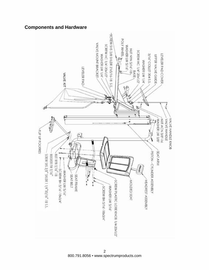
The boxes will contain all structural components and hardware. The following is a list of the
components included with your shipment from Spectrum. Use Components and Hardware
Figure, page 2, as a reference to identify each item listed.
1 Cylinder Assembly 1 Seat Arm
1 Headrest 1 Footrest
1 Seat Frame 1 Base
1 50 ft Hose 1 Leveler Pad Cover
1 Hardware Box
2 800.791.8056 ▪ www.spectrumproducts.com
Components and Hardware

3 800.791.8056 ▪ www.spectrumproducts.com
Installation Overview Read all instructions before attempting to assemble or install the Lift.
If you purchased and installed a Swim-Lift® Pre-Set Anchor previously or if your Retro-Fit
Anchors are already installed, please proceed to the Lift Assembly Section on page 7.
Anchor Location
It is recommended that the Lolo be installed in or near the shallow end of the pool with sufficient
deck space and operational area in the pool as shown in Figure 2. For reasons of safety and
ADA guidelines, the lift must be installed in a location that is clear from obstacles and other
hazards.
NOTE: Do not locate the lift in a corner or directly adjacent to pool ladders/handrails or grab rails
that could interfere with the rotation of the lift. Do not place the lift where it may be cumbersome
or hazardous to any pool users.
Figure 1
Because the lift can be stopped at any position during lowering, there is no minimum pool depth
requirement for the Lolo. However, to comply with ADA guidelines, the Lolo must be installed at
a pool depth no greater than 48-inches and the seat should submerge to a minimum depth of
18” below the surface of the water. For the standard base, anchors may be installed between
20” and 30” back from the pool/spa edge with the recommended anchor setback at 28”. For the
Short base, anchors may be installed between 18” and 24” back from the pool/spa edge with the
recommended anchor setback at 22”. Make sure that the centers of both anchors are the same
distance from the edge of the pool. There must be at least 6” from the center of each anchor to
the nearest joint, crack, curb or similar concrete structure to ensure the strength of the concrete.
Refer to Figure 3 to optimize the position of the leveler foot.
In addition, all installations should be in accordance with the ADA guidelines (ADA guidelines
are available at the website www.access-board.gov).

4 800.791.8056 ▪ www.spectrumproducts.com
NOTE: Optional base stand configurations are available if this setback range or anchor location
will not work with your pool.
Anchor Installation
1. Mark the location of each anchor on the deck and use a ½” diameter concrete drill bit to drill
a 4” deep hole at each location. Make sure to drill straight down.
Figure 2
2. Use a 1-1/2” diameter concrete core drill to drill out the anchor holes to a depth of 2-3/16” as
shown in Figure 4. Clean all of the debris from the holes. Check to see that the bottom of
each hole is in solid concrete. The anchors will only hold if the surrounding concrete is
solid. The top of the anchor should be ¼” below the deck surface. The anchors can be
installed deeper, if necessary, to mount to sufficiently solid concrete.
Figure 3
3. Use a small amount of two-part epoxy or hydraulic cement in each anchor hole and set an
anchor into each hole. Set the expansion anchor at the bottom of the anchor hole by
tapping the anchor pin with the supplied ¼” diameter set tool rod with a hammer. Use a
9/16” deep well socket to tighten the internal anchor bolt to approximately 30 ft-lbs. Torque.
Allow sufficient time for the epoxy or cement to completely harden before installing the lift in
the anchors.

5 800.791.8056 ▪ www.spectrumproducts.com
4. Locate a bonding source to bond (ground) the anchor. The steel rebar-bonding grid of the
pool deck is the best choice for bonding the anchor. Attach a No. 8 solid copper wire (not
included) from the bonding bolt on the base of the anchor to the bonding grid.
NOTE: Article 680 of the National Electrical Code requires bonding of all metallic components in
relationship to pools and spas.
Lift Assembly
1. Attach the Base to the Cylinder Support Column Assembly with four 3/8” – 16 x 4-1/2” hex
head bolts protruding from the support column, as shown on page 2. Secure the Base with
four 3/8” lock washers and four 3/8” acorn nuts, torque to 20 lb-ft.
2. Install the Pressure Wheel and the Pressure Wheel Guard using a 3/8”x 5 ½” hex head bolt,
two 3/8” flat washers, a 3/8” lock washer, and a 3/8” acorn nut.
3. Remove the upper valve handle knob from the valve handle and slide the valve handle
through the valve handle bracket. Match the flat on the valve post to the flat on the inside of
the valve handle sleeve and slide the valve handle onto the valve post. Replace the upper
valve handle knob on the valve handle.
4. Remove the upper valve handle knob from the valve handle and slide the valve handle
through the valve handle bracket. Match the flat on the valve post to the flat on the inside of
the valve handle sleeve and slide the valve handle onto the valve post. Replace the upper
valve handle knob on the valve handle.
NOTE: The two-piece collar on the valve handle holds the valve handle in place and may need
to be repositioned. To move the collar, loosen the screws in the collar using a 7/64” hex key
wrench. Move the collar so that it is just below the valve handle bracket and retighten the
screws. See Page 2.
6 800.791.8056 ▪ www.spectrumproducts.com
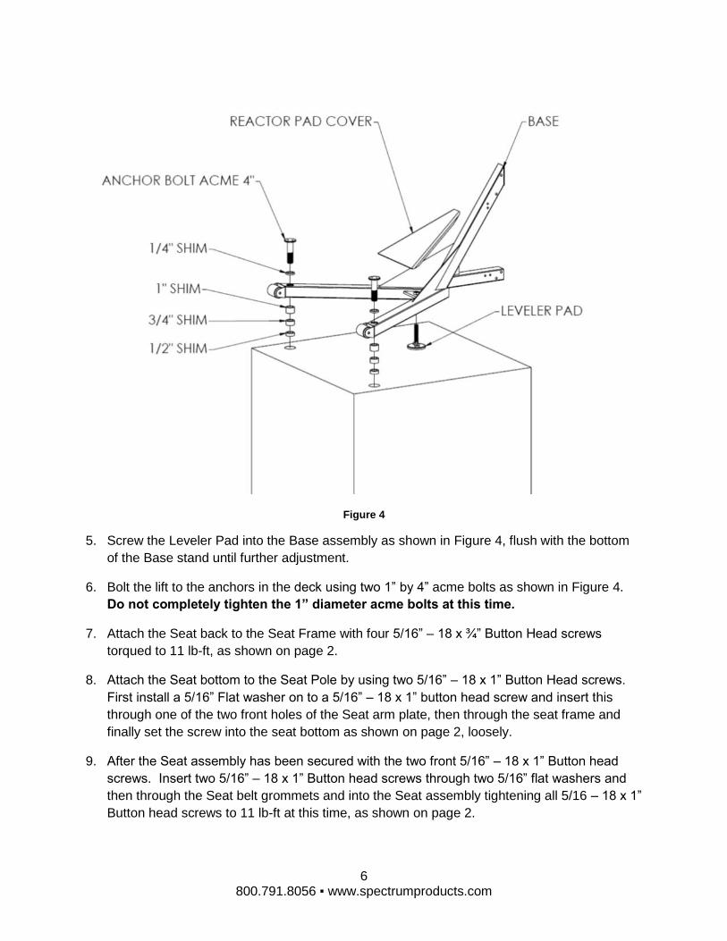
Figure 4
5. Screw the Leveler Pad into the Base assembly as shown in Figure 4, flush with the bottom
of the Base stand until further adjustment.
6. Bolt the lift to the anchors in the deck using two 1” by 4” acme bolts as shown in Figure 4.
Do not completely tighten the 1” diameter acme bolts at this time.
7. Attach the Seat back to the Seat Frame with four 5/16” – 18 x ¾” Button Head screws
torqued to 11 lb-ft, as shown on page 2.
8. Attach the Seat bottom to the Seat Pole by using two 5/16” – 18 x 1” Button Head screws.
First install a 5/16” Flat washer on to a 5/16” – 18 x 1” button head screw and insert this
through one of the two front holes of the Seat arm plate, then through the seat frame and
finally set the screw into the seat bottom as shown on page 2, loosely.
9. After the Seat assembly has been secured with the two front 5/16” – 18 x 1” Button head
screws. Insert two 5/16” – 18 x 1” Button head screws through two 5/16” flat washers and
then through the Seat belt grommets and into the Seat assembly tightening all 5/16 – 18 x 1”
Button head screws to 11 lb-ft at this time, as shown on page 2.

7 800.791.8056 ▪ www.spectrumproducts.com
10. Level the lift front to back, if necessary, by using donut shims between the base stand and
each anchor, and adjusting the Leveler Pad by screwing the Pad in or out. The donut shims
can be used individually or in combination to level the lift. The donut shims can be used
above the anchor base or below as shown in Figure 4 to prevent the acme bolts from
bottoming out in the anchors.
11. Check that the cylinder is perpendicular to the deck in all directions with a carpenter’s level.
Adjust the Leveler pad or change donut shims at each anchor to level the lift. If the lift is not
installed level and perpendicular, it may lower the lifting capacity, reduce the operational life
of the lift or void the warranty.
12. Install Cover on lift as shown in Figure 4.
Connect Flip up footrest using one 3/8” – 16 x 1 ¼” Socket head shoulder screw, a 3/8” Flat
washer and, a 3/8” nylock. Torque to screws 20 ft-lb as shown on page 2.
13. Install Headrest assembly in the receiver on the back of the seat frame and secure with the
plastic Lobe knob screw as shown in figure 1.
14. Connect the water supply to the female garden hose coupling on the control valve. After
purging the air (See lift preparation step three) from the cylinder the Swim-Lift® Lolo is ready
for operation.

8 800.791.8056 ▪ www.spectrumproducts.com
Lift Operation WARNING! Read all operating instructions before operating the lift. Make sure that all
individuals using the lift have read the instructions and have been made aware of all safety
precautions.
WARNING! Do not exceed the maximum lifting capacity of 400 lbs (181.4 kg). This may result in
damage to the lift or personal injury. Other lift models are available for loads in excess of 400
lbs.
The Swim-Lift® Lolo is a water-powered lifting aid designed for use with water systems that
have a 55 PSI rating. This lift will function with as little as 45 PSI water pressure. Optional
pump kits are available for supplying a constant pressure of 55 PSI. Lifting capacities are
based on a continual pressure supply without pressure drops occasionally incurred during peak
demand periods of city water systems. The lifting capacity/pressure ratios are as follows:
Pressure Lift Capacity
55 PSI 400 lbs.
50 PSI 350 lbs.
45 PSI 300 lbs.
Note: A backflow check valve may be required on this lift to prevent contamination of the
municipal water supply. Please check your state and local codes to see if a backflow check
valve is required.
Lift Preparation:
1. Turn the control valve to the intermediate stop position and attach the water supply hose
to the valve. Turn the water supply on.
2. With no weight on the chair, turn the control valve handle to the up position. Allow the
chair to fully rise.
3. Turn the control valve handle to the down position. Allow the seat to lower to a fully
down position. Repeat steps 2 and 3 until a smooth operation is attained. This process purges
the air from the system and should not take more than 5 to 7 cycles to complete.
Lift Operation:
1. Lift operation is controlled through the use of the control valve. The valve handle turned
clockwise will lower the chair, and turned counter-clockwise will raise the chair. The chair will
stop at any point along its travel if the valve handle is turned to an intermediate position.
Excessive force is not required to turn the valve handle. Instruct all operators on proper use of
the control valve prior to operation of the lift.
2. The outer chair arm flips up and back for ease of transfer from a wheelchair to the lift
seat. In addition, the stationary arm on the inside of the chair may assist in transferring. Use of

9 800.791.8056 ▪ www.spectrumproducts.com
the seatbelt is recommended for all users. To facilitate safe loading and unloading of
inexperienced users, we recommend that an attendant always be present. Instruct all operators
on the proper use of the chair features and the transfer procedure.
3. A lock pin is attached to the top of the cylinder to lock the chair in the fully raised position
or rotated 180° over the pool. Push the pin through the piston rod (lower hole) to lock the chair
in the fully raised position when the lift is not in use and/or when the water supply is turned off.
Use the 180° rotated lock pin hole (upper hole) to lock the chair in place when removing the lift
from the anchors.
4. Keep other swimmers and children away from the lift at all times. Remove the lift from
poolside when not in use if possible. A cover (part # 25186) is available from Spectrum
Products® to aid in preventing unauthorized use of the lift.
5. To drain the water from the lift for storage: disconnect the water source, turn the control
valve to down, push the chair down, turn the control valve to up, and push the chair back up.
Repeating this step is necessary to get all of the water removed. This process will force the
water from the cylinder, valve and hoses.

10 800.791.8056 ▪ www.spectrumproducts.com
Care and Maintenance The following should be performed periodically to ensure safe and dependable use.
1. Remove any discoloration with a 3M scratch pad (stainless steel components only).
Wipe clean with a sponge dampened with Spectra Clean. Repeat these steps several
times to passivate the stainless steel. Spectra Clean kits are available from Spectrum
(Part Number 202050-00). Do not spray with high-pressure water, only clean with non-
chlorinated water.
2. Check all water connections – Check any external hoses for wear and/or breakage in the
outer tubing.
3. Check all mechanical connections – inspect the Nylock Nuts on all moving parts and
make sure they are snug.
4. To ensure safe and dependable use, periodically disengage the deck anchors and
lubricate the acme thread nut with a small amount of petroleum jelly. Also, check that
the inside bolt is tight. If it is loose or corroded, replace it immediately. Do not operate
the lift until the bolt is replaced.

11 800.791.8056 ▪ www.spectrumproducts.com
Troubleshooting Problem: Cause: Solution:
1. Lift will not operate at all: Unit Not Level
Valve Failure
Kinked Hose
Air in Cylinder
Dirty Cylinder
Worn Top Collar
Check for level and shim
accordingly
Replace Valve (P/N 27285,
27286)
Un kink hose and recheck
Run unit 5-7 times up and down
while assisting motion
Call for assistance
Replace Top Collar (P/N
27315)
2. Lift chatters when moving. Air in Cylinder
Dirty Cylinder
Worn Top Collar
Run unit 5-7 times up and down
while assisting motion
Call for assistance
Replace Top Collar (P/N
27315)
3. Lift moves up slowly Low water pressure
Worn Seals
Valve Failure
Use lift with Booster Pump (P/N
27028-00)
Replace Seals (P/N 27245,
27246)
Replace Valve (P/N 27285,
27286)
4. The seat travels much slower
than normal.
Low battery
Defective or worn-out
battery
Recharge battery
Replace battery*
5. Lift descends with valve in
neutral position
Valve Failure
Worn Seals
Replace Valve (P/N 27285,
27286)
Replace Seals (P/N 27245,
27246)
*Please contact your local distributor or Spectrum Customer Service to order parts 406.532.6321


![[XLS]obcindia.co.inobcindia.co.in/obcnew/upload/obc/Unpaid Dividend 2013-14... · Web view400 400 400 400 400 400 400 400 400 400 400 400 400 400 400 400 400 400 400 400 400 400 400](https://static.fdocuments.in/doc/165x107/5aa6f94e7f8b9a54748b6a16/xls-dividend-2013-14web-view400-400-400-400-400-400-400-400-400-400-400-400.jpg)