Logo Motion Edition B Internet
188
6800/7000 Series LogoMotion Products Installation and Operation Manual 175-000075-00 Edition B
Transcript of Logo Motion Edition B Internet

F.fm Page 1 Thursday, January 16, 2003 3:42 PM
6800/7000 SeriesLogoMotion ProductsInstallation and Operation Manual
175-000075-00Edition B

F.fm Page 2 Thursday, January 16, 2003 3:42 PM
Trademarks and Copyright
ADAC, ADCOE, AgileVision,
BOS,
Broadcast
Operating
system, CCS,
CoPilot, DigiBus, DigiPeek,
Digital
Glue,
DigiWorks, DPS,
DTV
Glue,
Engineering The
Big
Picture,
EventWORKS,
EZ
HD,
Focused
on
the
Future,
Genesis, HDTV
Glue,
HEDCO,
Innovision,
ISIS,
JUNO,
LeFont,
Leitch,
Leitch Network
Systems,
LNS,
LogoMAX,
LogoMotion,
MediaFile,
MediaPort, MIX
BOX,
Monarch,
Motion
File, NEO,
OPUS,
PanelMAPPER,
Pilot, Portal, PROM-Slide,
RouterWORKS,
StillFile,
Still
Net,
Tekniche,
Unilock, VIA,
ViewGuard, Whiplash2,
Xplus,
and
Leitch
XPRESS
are
trademarks and/or
registered
trademarks
of
Leitch
Technology
Corporation
in the
United States,
Canada,
and/or
other
countries.
All other
trademarks
are
the
property
of
their
respective
owners.
Copyright 2002,
Leitch Incorporated.
All
rights
reserved.
This
publication
supersedes all
previous
releases.
Printed
in
Canada.

6800/7000 SeriesLogoMotion
Products
Installation and Operation Manual
Edition BNovember 2002


Preface
Purpose
This manual details the features, installation procedures, operational procedures, and specifications of the 6800/7000 Series of LogoMotion Products.
Audience
This manual is written for technicians and operators responsible for installation, setup, and/or operation of the 6800/7000 Series of LogoMotion Products.
Writing Conventions
To enhance your understanding, the authors of this manual have adhered to the following text conventions:
Bold Indicates dialog box, property sheet, field, button, checkbox, listbox, combo box, menu, submenu, window, list, and selection names.
Italics Indicates email addresses, names of books and publications, and first instances of new terms and specialized words that need emphasis.
CAPS Indicates a specific key on the keyboard, such as ENTER, TAB, CTRL, ALT, DELETE.
Code Indicates variables or command-line entries, i.e., a DOS entry, something you type into a field, etc.
> Indicates direction of navigation through a hierarchy of menus and windows.
hyperlink Indicates a jump to another location in the document or elsewhere (such as a website).
6800/7000 Series - LogoMotion Installation and Operation Manual iii

Preface
Revision History
Edition Date Revision History
A May 1998 Initial release
B November 2002 • Updated information
• General reformatting and reorganization of material
iv 6800/7000 Series - LogoMotion Products Installation and Operation Manual

Preface
Summary of the 6800/7000 Series Product Manuals
Audio/Video/Mux and Demultiplexing ManualChapter 1 ADC-6801 CAV to SDI Converter Module
Chapter 2 ADC-6880 Analog to AES/EBU Digital Converter
Chapter 3 ADM/ASM-680x Embedded Audio Monitoring Module
Chapter 4 DAC-6801 Digital to Analog Component Converter
Chapter 5 DAC-6880 AES/EBU Digital Audio to Analog Audio Converter
Chapter 6 DEC-6801/DES-6801 Decoder/Decoder with Frame Synchronizer Module
Chapter 7 DEC-6804 Decoder and DES-6804 Decoder with Frame Synchronizer
Chapter 8 ENC-ENS/ENX-6801A Encoder Modules
Chapter 9 MXA-6800-AES and MXA-6801-A2/A4 Audio Multiplexer Module
Chapter10 VFS-6801 Serial Component Frame Synchronizer Module
Chapter 11 VTS-6801 Video Timing Switcher
Appendix A Embedding Modes Graphic Description
Test Series ManualChapter 1 VTG-6801-1 &VTG-6801-1A 4:2:0 & 4:2:2 Serial Digital
Test Generator Module
Chapter 2 VTG-6801-2 Serial Digital Test Generator Module
Chapter 3 DAR-6880 AES/EBU Digital Audio Reference and Tone Generator
Chapter 4 SAI-6800 4:2:2 Safe Area Generator/Inserter Module
Chapter 5 VTG-6800 MIX BOX Frame and Control Assembly
Chapter 6 EDH-6800MB Detection and Handling MIX BOX
6800/7000 Series - LogoMotion Products Installation and Operation Manual v

Preface
Distribution and Routing ManualChapter 1 AES-6880 AES/EBU Digital Audio Distribution Amplifier
Module - General
Chapter 2 DNH-6800 DigiNet Hub Module
Chapter 3 EDH-6800-2EDH Detection/Insertion Serial Distribution Amplifier Module
Chapter 4 USM-6800 PAL/NTSC Monitoring Encoder Module
Chapter 5 VDA-6830 Video Distribution Amplifier Module
Chapter 6 VEA-6830 Video Equalizing Amplifier Module
Chapter 7 VEA-6840 Video Equalizing Amplifier Module
Chapter 8 VPD-6830 Programmable Video DA series
Chapter 9 VSD-6801 Serial Digital Distribution Amplifier Module
Chapter 10 VSE-6801 Serial Equalizing Amplifier Module
Chapter 11 VSE-6802 Serial Equalizing Distribution Amplifier
Chapter 12 VSM-6802 Digital Composite Video Signal
Chapter 13 VSM-6804 Digital Composite Video Signal Monitor Module
Chapter 14 VSR-4041 Serial Video Router Module
LogoMotion ManualChapter 1 Logo Utilities for 6800 Series Modules
Chapter 2 LGI-6801 Serial Digital Logo Generator/Inserter Module
Chapter 3 VES-6801 Flash EPROM Side Module
Chapter 4 DSK-6801/3 Downstream Serial Keyer
Chapter 5 DSK-CP1/2 Downstream Serial Keyer Control Panel
vi 6800/7000 Series - LogoMotion Products Installation and Operation Manual

Preface
Frames and Power Supply ManualChapter 1 Mounting Frames
Chapter 2 FR-6801/FR-6801-1 Frames
Chapter 3 FR-6804/FR-6804-1 Frames
Chapter 4 CF-6801 Cooling Frame
Chapter 5 FR-7001 and FR-7000MB Mix Box
Chapter 6 6801 ps Power Supply Module
Chapter 7 6804(-1) Power Supply Module
Chapter 8 7000 Power Supply Module
Chapter 9 6801 ps-48 Power Supply Module
Chapter 10 6804 ps-1-48 Power Supply Module
6800/7000 Series - LogoMotion Products Installation and Operation Manual vii
Preface
Unpacking/Shipping InformationThis product has been carefully inspected, tested and calibrated before shipment to ensure years of stable and troublefree service. Please check the equipment for any visible damage which may have occurred during transit.
Please confirm that all items listed on the packing list have been received. If any item on the packing list is missing, please contact your Leitch dealer. If any item is damaged, please contact the carrier. Ensure that all packaging material is removed from the product and its associated components before installing the unit.
It is suggested that you keep at least one set of original Leitch packaging, in the event that a product needs to be returned for service. If the original packaging is not available, you can purchase replacement packaging from Leitch at a modest cost or supply your own packaging as long as it meets the following criteria:
• Packaging must be able to withstand the product weight.
• Product must be held rigid within the packaging.
• There must be at least 2 inches of space between the product and the container.
• The corners of the product must be protected.
Products that are being returned to Leitch for servicing should be shipped prepaid in the original packaging material if possible. If the product is still within the warranty period, the product will be returned by prepaid shipment after servicing.
Installation InformationIf this product is rack-mountable, it should be mounted in an appropriate rack using the rack mounting positions and rear support guides provided. It is recommended that each frame be connected to a separate electrical circuit for protection against circuit overloading. If this product relies on forced air cooling, it is recommended that all obstructions to the air flow be removed prior to mounting the frame in the rack.
If this product has a provision for external earth grounding, it is recommended that the frame be grounded to earth via the protective earth ground on the rear panel.
viii 6800/7000 Series - LogoMotion Products Installation and Operation Manual

Preface
Important Safety InstructionsReview the following safety precautions to avoid injury and prevent damage to this product or any products connected to it. Read these instructions. Keep these instructions. Heed all warnings. Follow all instructions.
Servicing
Only qualified personnel should perform service procedures. Refer all servicing to qualified service personnel. Servicing is required when the apparatus has been damaged in any way, such as power-supply cord or plug is damaged, liquid has been spilled or objects have fallen into the apparatus, the apparatus has been exposed to rain or moisture, does not operate normally, or has been dropped.
Safety Terms and Symbols
Terms and Symbols in This Manual
Terms and Symbols on the Product
WARNING: Statements identifying conditions or practices that can result in personal injury or loss of life: High voltage is present. Uninsulated dangerous voltage within the product’s enclosure may be sufficient to constitute a risk of electric shock to persons.
CAUTION:Statements identifying conditions or practices that can result in damage to the equipment or other property: Important operating and maintenance (servicing) instructions in the literature accompanying the product.
DANGER: High voltage and indicates a personal injury hazard immediately accessible as one reads the marking.
WARNING: Indicates a personal injury hazard not immediately accessible as one reads the marking.
CAUTION: Indicates a hazard to property including the product or to take attention and refer to the manual.
6800/7000 Series - LogoMotion Products Installation and Operation Manual ix

Preface
Injury Precautions
Protective ground (earth) terminal.
Fuse: Replace with same type and rating of fuse.
Observe precautions for handling electrostatic-sensitive devices.
WARNING!To reduce the risk of electric shock, do not expose this apparatus to rain or moisture.
WARNING! Potentially lethal voltages are present within this product’s frame during normal operation. The AC power cord must be disconnected from the frame before the top panel is removed. (In frames with multiple power supplies, remove ALL power cords.) Power should not be applied to the frame while the top is open, unless properly trained personnel are servicing the unit.
[PL Poland] Przod zdjeciem pokrywy wyciagnac wtyczke z gniazda sieciowego.
[French] AVIS: RISQUE DE CHOC ELECTRIQUE - NE PAS OUVRIR. INSTALLER SUR SUPPORT DE MONTAGE SEULEMENT.
CAUTIONRISK OF ELECTRIC SHOCK
DO NOT OPEN
x 6800/7000 Series - LogoMotion Products Installation and Operation Manual

Preface
AVIS - Risque de choc electrique. Ne pas ouvrir.
6800/7000 Series - LogoMotion Products Installation and Operation Manual xi

Preface
Use Proper Power CordTo avoid fire hazard, use only the power cord specified for this product.
Ground the ProductDo not defeat the safety purpose of the polarized or grounding-type plug. A polarized plug has two blades with one wider than the other. A grounding type plug has two blades and a third grounding prong. The wide blade or the third prong are provided for your safety. When the provided plug does not fit into your outlet, consult an electrician for replacement of the obsolete outlet.
[United Kingdom] WARNING: THIS APPLIANCE MUST BE EARTHED.
[Sweden] APPARATEN SKALL ANSLUTAS TILL JORDAT UTTAG NÄR DEN ANSLUTS TILL ETT NÄTVERK.
Do Not Operate Without CoversTo avoid electrical shock or fire hazard, do not operate this product with covers or panels removed.
Use Proper FuseTo avoid fire hazard, use only the fuse type and rating specified for this product.
Do Not Operate in Wet/Damp ConditionsTo reduce the risk of fire or electric shock, do not expose this apparatus to rain or moisture.
Do Not Operate in an Explosive AtmosphereTo avoid injury or fire hazard, do not operate this product in an explosive atmosphere.
Avoid Exposed CircuitryTo avoid injury, remove jewelry such as rings, watches, and other metallic objects. Do not touch exposed connections and components when power is present.
xii 6800/7000 Series - LogoMotion Products Installation and Operation Manual

Preface
Product Damage Precautions
Use Proper Power SourceDo not operate this product from a power source that supplies more than the specified voltage.
Use Proper Voltage SettingBefore applying power, ensure that the line selector is in the proper position for the power source being used.
Provide Proper VentilationTo prevent product overheating, provide proper ventilation.
Do Not Block Any Ventilation OpeningsDo not block any of the ventilation openings. Install in accordance with the manufacturer’s instructions.
Only Use Attachments/Accessories Specified by the Manufacturer
Do Not Operate With Suspected FailuresRefer all servicing to qualified service personnel. Servicing is required when the apparatus has been damaged in any way, such as power-supply cord or plug is damaged, liquid has been spilled or objects have fallen into the apparatus, the apparatus has been exposed to rain or moisture, does not operate normally, or has been dropped.
For Products with Multiple Power Cords:CAUTION: This unit can have more than one power supply cord. To de-energize the internal circuitry, disconnect all power cords before servicing.
[Norwegian] ADVARSEL: Utstyret kan ha mere ennn en tilførselsledning. For å gjore interne deler spennigsløse må alle tilførselsledningene trekkes ut.
[Sweden] VARNING: Denna apparat har mer än en nätanslutning. Samtliga nätkablar måste bortkopplas för att göra de interna kretsarna spänningsfria.
6800/7000 Series - LogoMotion Products Installation and Operation Manual xiii

Preface
Do Not Use This Apparatus Near WaterDo not expose this apparatus to dripping or splashing water. Ensure that no objects filled with liquid, such as vases or cups, are placed on the apparatus.
Clean Only With a Dry Cloth
Keep Product Away from Heat SourcesDo not install near any heat sources such as radiators, heat registers, stoves, or other apparatus (including amplifiers) that produce heat.
Install Near Socket OutletThe equipment shall be installed near the socket outlet, and a disconnect device shall be easily accessible.
Unplug this Apparatus During Lightning StormsUnplug this apparatus during lightning storms or when unused for long periods of time. Note: A UPS or power surge suppressor could be used as an alternative.
Attention:Observe precautions for handling electrostatic-sensitive devices. See “Preventing Electrostatic Discharge” below for details.
Fuse Replacement:CAUTION: FOR CONTINUED PROTECTION AGAINST RISK OF FIRE, REPLACE ONLY WITH THE SAME TYPE OF FUSE.[French]ATTENTION: REMPLACER UNIQUEMENT PAR UN FUSIBLE DE MEME TYPE.
xiv 6800/7000 Series - LogoMotion Products Installation and Operation Manual

Preface
Battery Use Warnings
CAUTION: DANGER OF EXPLOSION IF BATTERY IS INCORRECTLY PLACED. REPLACE ONLY WITH THE SAME OR EQUIVALENT TYPE RECOMMENDED BY THE MANUFACTURER. DISCARD USED BATTERIES ACCORDING TO THE MANUFACTURER’S INSTRUCTIONS.
[FI Finland] VAROITUS: Paristo voi rajahtaa, jos se on virheellisesti asennettu. Vaihda paristo ainoastaan valmistajan suosittelemaan tyyppun. Havita kaytetty paristo valmistajan ohjeiden mukaisesti.
[SE Sweden] VARNING: Explosionsfara vid felaktigt batteribyte. Anvand samma batterityp eller en eller en ekvivalent typ som rekommenderas av tillverkaren. Kassera anvant batteri enligt fabrikantens instruktion.
[D Denmark]
[KO Korean]
Advarsel! Lithiumbatteri. Eksplosionsfare ved fejlagtig handtering. Udskiftning ma kun ske med batteri af samme fabrikat oq type. Lever det brugte batteri tilbage till leverandoren.
6800/7000 Series - LogoMotion Products Installation and Operation Manual xv

Preface
Preventing Electrostatic Discharge
CAUTION: Electrostatic discharge (ESD) can damage components in the product. To prevent ESD, observe these precautions when directed to do so:
• Use a Ground Strap. Wear a grounded antistatic wrist strap to discharge the static voltage from your body while installing or removing sensitive components.
• Use a Safe Work Area. Do not use any devices capable of generating or holding a static charge in the work area where you install or remove sensitive components. Avoid handling sensitive components in areas that have a floor or benchtop surface capable of generating a static charge.
• Handle Components Carefully. Do not slide sensitive components over any surface. Do not touch exposed connector pins. Handle sensitive components as little as possible.
• Transport and Store Carefully. Transport and store sensitive components in a static-protected bag or container.
xvi 6800/7000 Series - LogoMotion Products Installation and Operation Manual

Preface
Certifications and CompliancesThis product has been tested and found to comply with the following CE, FCC, UL, ICES and CSA standards:
EMC Standards
per the provision of the Electromagnetic Compatibility Directive 89/336/EEC of 3 May 1989 as amended by 92/31EEC of 28 April 1992 and 93/68/EEC, Article 5 of 22 July 1993.
These devices are for professional use only and comply with Part 15 of FCC rules. Operation is subject to the following two conditions:
1. These devices may cause interference to Radio and TV receivers in residential areas.
2. These devices will accept any interference received, including interference that may cause undesired operations.
These devices do not exceed the class A limits for radio noise emissions from digital apparatus as set out in the interference standard entitled “Digital apparatus”, ICES-003 of the Canadian Department of Communications.
Changes or modifications not expressly approved by Leitch, the party responsible for compliance to the FCC Part 15 Rule, could void the user’s authority to operate this equipment legally in the US.
EN55022 Limits and methods of measurement of radio disturbance characteristics of information technology equipment Class A.
EN55082-1 Generic immunity standard.
EN55103-1 Electromagnetic compatibility—Product family standard for audio, video, audio-visual and entertainment lighting control apparatus for professional use, Part 1: Emission, Environment E4.
ENC 1000-4-3 Radiated radio-frequency electromagnetic field immunity test 1V/m 1kHz 80% AM, 80-1000MHz.
ENC 1000-4-2 1995-01
Electrostatic discharge requirements “ESD”, 6kV CD, 8kN AD.
ENC 1000-4-4 1995-01
Electrical Fast transient requirements “Burst”, 0.5kV Sig. Lines, 1kV.
6800/7000 Series - LogoMotion Products Installation and Operation Manual xvii

Preface
Safety Standards
EN 60950-1992
Safety of information technology equipment, including electrical business equipment (Amendments A1: 1993, A2: 1993, A3: 1995, A4: 1997), per the provision of the Low-Voltage Directive 73/23/EEC of February 19, 1973 as amended by 93/68/EEC.
UL 1950 Safety of information technology equipment, including electrical business equipment.
CSA C22.2 No. 950-95
Safety of information technology equipment, including electrical business equipment.
xviii 6800/7000 Series - LogoMotion Products Installation and Operation Manual

Contents
Chapter 1: Logo Utilities for 6800 Series Modules .........1
Overview ......................................................................................................1
Installation and Setup .................................................................................2
System Requirements ..........................................................................2
Installing the Utilities for DOS-based Systems ...................................3
Installing the Utilities for Windows–Based Systems ..........................3
Graphic and Logo Creation ........................................................................4
Creating and Loading Logos ...............................................................4
Creating Graphics for Logo Use ..........................................................4
Using the Logo Graphics Conversion and Download Utilities ..........8
Running LogoDOS ..............................................................................8
Creating a New MGI File .....................................................................9
Sending an MGI File to Logo Generator ...........................................10
Additional LogoDOS Menu Options ................................................10
Running LogoWIN ............................................................................11
Communication Setup ......................................................................12
Logo Options .....................................................................................14
Creating a Logo File ...........................................................................15
Editing MGI Logo Files .....................................................................16
Installing Logos ..................................................................................17
Chapter 2: LGI-6801 Serial Digital Logo Generator/Inserter Module......................................................................................21
Overview ....................................................................................................21
Installation .................................................................................................22
Operation ..................................................................................................23
Controls .............................................................................................23
LED Indicators ...................................................................................23
6800/7000 Series - LogoMotion Products Installation and Operation Manual xix

Contents
Jumpers ............................................................................................. 23
Switches ............................................................................................. 24
GPI ..................................................................................................... 25
Frame ID ............................................................................................ 25
Specifications ............................................................................................ 26
Serial Video Input ............................................................................. 26
Serial Video Outputs ......................................................................... 26
General .............................................................................................. 27
Chapter 3: VES-6801 Flash EPROM Slide Module ......... 29
Overview ................................................................................................... 29
Installation ................................................................................................ 30
Operation .................................................................................................. 31
SW1 and SW2 Functions .................................................................. 31
LED Indicators .................................................................................. 33
Jumpers ............................................................................................. 35
Connectors ........................................................................................ 36
GPI ..................................................................................................... 38
Test Points ......................................................................................... 39
Slide Download ................................................................................. 40
Creating, Recording and Downloading Slides ................................. 40
Specifications ............................................................................................ 41
Serial Outputs .................................................................................... 41
Analog Reference .............................................................................. 42
Control .............................................................................................. 42
Power Requirements ......................................................................... 42
Chapter 4: DSK-6801/3 Downstream Serial Keyer ....... 43
Overview ................................................................................................... 43
DSK-6801 Keyer Features ................................................................. 44
DSK-6803 Keyer Features ................................................................. 45
Installing and Setup .................................................................................. 46
System Setup Considerations ........................................................... 46
DSK-6801 Rear Module Connectors ................................................ 48
DSK-6803 Rear Module Connectors ................................................ 50
DSK-6801/3 LEDs Layout ................................................................. 52
BNC Selection, Jumper Setup, and Switch Setup ............................. 53
Control Selection ............................................................................... 56
xx 6800/7000 Series - LogoMotion Products Installation and Operation Manual

Contents
Keyer Module Controls ..................................................................... 57
Settings for Shift State 0: General Functions .................................... 62
Settings for Shift State 1: Extended Setup ......................................... 68
Settings for Shift State 2: Configuration ........................................... 71
GPI Control ....................................................................................... 79
Parameter Range List and Key Descriptions .................................... 80
Video Processing ............................................................................... 87
Board Control .................................................................................... 87
Specifications ............................................................................................ 88
Chapter 5: DSK-CP1/2 Downstream Serial Keyer Control Panel.............................................................. 91
Overview ................................................................................................... 91
Features ............................................................................................. 94
Detailed Layout and Overview ................................................................. 95
Dedicated Transition Buttons ........................................................... 96
Programmable Soft Buttons .............................................................. 98
The Menu System ................................................................................... 104
Contents of a Menu ......................................................................... 108
Menu Controls ................................................................................ 108
Menu and Property Descriptions ................................................... 110
Modes of Operation ................................................................................ 130
Individual Mode .............................................................................. 130
Group Mode .................................................................................... 130
Transitioning Multiple Keyers with Different Settings .................. 131
Program/Preview Mode .................................................................. 131
Setting the Device Address ..................................................................... 132
Setting a Group ID .......................................................................... 132
Setting a Keyer ID ............................................................................ 133
Setting a Device Address ................................................................. 134
Setting the Panel ID ......................................................................... 135
Installation .............................................................................................. 136
Rear Module XY Connections ........................................................ 136
DSK Keyer Module Setup Requirements ....................................... 138
System Applications ............................................................................... 139
Connecting a Single Keyer System .................................................. 140
Connecting a Multi-Level Keying System ...................................... 141
Connecting a Program/Preview System ......................................... 142
6800/7000 Series - LogoMotion Products Installation and Operation Manual xxi

Contents
Procedure for Setup of a Program/Preview System ....................... 143
Connecting a Group System ........................................................... 145
Appendix A: Quick Reference Guide.................................... 149
Overview ................................................................................................. 149
Setting Control for One or More Keyers ................................................ 150
DSK Control Layout ....................................................................... 151
Menus .............................................................................................. 153
Selecting and Changing a Menu ..................................................... 155
Summary of Control Modes ........................................................... 155
XY Bus Connections ....................................................................... 156
Setting a Device Address ................................................................. 157
Error Messages ........................................................................................ 158
Troubleshooting ..................................................................................... 160
Diagnostic Mode .................................................................................... 161
Control Panel Self-Test ................................................................... 161
xxii 6800/7000 Series - LogoMotion Products Installation and Operation Manual

Chapter 1
Logo Utilities for 6800 Series Modules
OverviewLogoMotion™ Utilities are a set of Windows® and DOS applications used to create and download MGI files to the LogoMotion™ products and 6800 series modules. Utilities are distributed on several floppy disks. Installation is simple, and is described in more detail for both DOS- and Windows-based systems.
Specifications and designs are subject to change without notice.
6800/7000 Series - LogoMotion Products Installation and Operation Manual 1
Chapter 1: Logo Utilities for 6800 Series Modules Installation and Setup
Installation and Setup
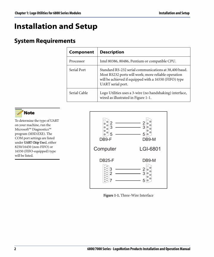
System Requirements
Figure 1-1. Three-Wire Interface
Component Description
Processor Intel 80386, 80486, Pentium or compatible CPU.
Serial Port Standard RS-232 serial communications at 38,400 baud. Most RS232 ports will work; more reliable operation will be achieved if equipped with a 16550 (FIFO) type UART serial port.
Serial Cable Logo Utilities uses a 3-wire (no handshaking) interface, wired as illustrated in Figure 1-1.
235
DB9-F
235DB9-M
235
DB9-M
327
DB25-F
Computer LGI-6801
To determine the type of UART on your machine, run the Microsoft™ Diagnostics™ program (MSD.EXE). The COM port settings are listed under UART Chip Used, either 8250/16450 (non-FIFO) or 16550 (FIFO-equipped) type will be listed.
2 6800/7000 Series - LogoMotion Products Installation and Operation Manual

Installation and Setup Chapter 1: Logo Utilities for 6800 Series Modules
Installing the Utilities for DOS-based Systems
To install on a DOS-based system, insert the first floppy disk into your computer. Depending on whether your floppy drive is A or B a:\setupdos or b:\setupdos.
Installing the Utilities for Windows–Based SystemsTo install on a Windows-based system, simply insert the first floppy disk into your computer and follow the directions below.
Item Description
LogoDos Memory–640KB base memory 500 KB available. Requires approximately 1.5 MB of XMS memory, using a memory manager such as HIMEM, QEMM, 386MAX, etc.
Video–Any CGA, EGA, VGA, or SVGA graphics card operating in TEXT mode.
Load the ANSI driver–(ANSI.SYS)
LogoWIN Memory–Minimum 8 MB RAM, 16 MB preferred.The setup utility will load all appropriate software by default into the C:\LOGOMOTN directory.
Operating System Instructions
Windows 3.1 systems Open the File Manager, select File>Run and type: a:\setup or b:\setup.
Windows 95 systems Click the Start button, click Run and then type:a:\setup or b:\setup.
The setup utility will load all appropriate software by default into the C:\LOGOMOTN directory.
6800/7000 Series - LogoMotion Products Installation and Operation Manual 3

Chapter 1: Logo Utilities for 6800 Series Modules Graphic and Logo Creation
Graphic and Logo Creation
Creating and Loading LogosYou can load customer-designed logos into 6800 series modules using the Leitch Logo Graphics Conversion and Download Utilities. These utilities allow the conversion of customer-created graphics files from a variety of industry-standard graphics formats into the format required. You can then download the converted files from a computer into the module, using a serial port interface.
Creating Graphics for Logo Use
Creating Master Artwork
Create the logo artwork using a standard drawing or paint program. The LogoMotion Utilities require two graphics files: one for the video (Fill) signal and one for the Key signal to generate an MGI file.
The LGI-6801 uses both the Fill video signal and the Key signal. The VES-6801 uses only the Fill signal.
If you are not familiar with the concept of keying and Key signals, we recommend that you research this topic thoroughly before proceeding to create graphics artwork for logo use. Linear keying is perhaps the largest challenge in the creation of quality logos for on-air use. Leitch has available several Applications Notes that describe Keying in detail. Contact your local Leitch representative, or visit us at http://www.leitch.com.
Most drawing/paint programs allow you to select the pixel resolution and color depth. These selections can greatly affect the quality of the final logo. See “Selecting the Pixel Size and Color Resolution of the Graphic” on page 5 for further information.
Both the Fill and the Key signals must be sized and processed identically. Otherwise, the two will not align, and the keyed result may appear misaligned. Many graphics programs provide for the manipulation of many simultaneous channels together, simplifying this task. On some systems that do not provide for Alpha or Key channels, a separate graphics file must be created and processed identical to that of the Fill graphics file.
The 6800 series module does not create the logo. The module acts only as the recorder, storage, playback, and Keyer for externally created logos.
4 6800/7000 Series - LogoMotion Products Installation and Operation Manual

Graphic and Logo Creation Chapter 1: Logo Utilities for 6800 Series Modules
Selecting the Pixel Size and Color Resolution of the Graphic
Most drawing/paint programs allow you to select the size of the graphics file, which is typically measured in pixels. The choice of pixel resolution can affect the quality and size of the graphics file.
6800 series modules are serial digital products that store all logos according to the CCIR-601 format. Another term commonly used to denote the CCIR-601 format is 4:2:2(:4). This format defines a horizontal video line to be 720 pixels wide, with the number of vertical pixels (also referred to as lines) depending on the line standard in use. For 525/60 systems, the number of active video lines is 486, and for 625/50 systems, the number of active video lines is 576.
A video Fill Key signal is stored in full color, with three channels of video components. For the purposes of this discussion, we will assume that the three channels are red, green, and blue (RGB). The second video image stored is a linear Key signal (a monochrome signal composed of a single luminance channel). Other terms used to denote the linear Key signal are: Key, Alpha, and Matte channel.
For CCIR-601 purists: Although the CCIR-601 specification defines the three video channels as Y/Cb/Cr, most graphics systems operate only in the RGB domain. The Logo Utilities automatically convert from the RGB domain to Y/Cb/Cr domain. The Cb/Cr channels have one-half the number of pixels as the Y channel. Because the Utilities require the full number of pixels in the RGB domain, they will correctly create the Y/Cb/Cr pixels for the final logo file.
The Logo Utilities work with all pixel resolutions and color depths. Best results can be achieved with specific pixel resolutions and color depths.
The “ideal” pixel resolutions for the 6800 series modules are:
• 525/60 operation: 720 horizontal pixels x 486 vertical pixels/lines
• 625/50 operation: 720 horizontal pixels x 576 vertical pixels/lines
The “ideal” Key Fill color depths are:
• Fill graphic images: 24 bits per pixel (8 bits per RGB)
• Key graphic images: 8 bits per pixel (luminance or grayscale only)
The VES-6801 can store 30-bit RGB images as 10-bit Y/Cb/Cr.
It is better to operate in the highest possible resolutions, rather than lower ones. The Logo Utilities automatically scale all graphic files to the correct resolutions for use in 6800 series modules.
The LGI-6801 stores two video images for each logo (Fill and Key signals). The VES-6801 stores one image for each logo (Fill only).
6800/7000 Series - LogoMotion Products Installation and Operation Manual 5

Chapter 1: Logo Utilities for 6800 Series Modules Graphic and Logo Creation
Aspect Ratios and the Ubiquitous Square Pixel
The aspect ratio for almost all video screens in the television and graphics world is typically 4:3. This implies that the horizontal width is 1/3 larger than the vertical height. However, a pixel in the television world is not the same size as a pixel in the computer graphics world.
Computer graphics generally use a square pixel. Typical screen resolutions in the computer graphics world are 640 x 480, 800 x 600, 1024 x 768, etc., all of which are exactly a 4:3 ratio. Since the screen pixel aspect ratio matches the screen physical aspect ratio, each pixel is square. This means, for example, that a box that is 50 pixels wide and 50 pixels high will appear as a square with four equal-length sides.
Television systems operate with the same ratio video screens (4:3), but the ratio of the number of pixels to the number of lines is not 4:3. In the 525/60 world, a 720 x 486 image works out to a ratio of 4:2.7. In the 625/50 world, a 720 x 576 image works out to a ratio of 4:3.2.
When graphics are created on a computer graphics system with square pixels, and then transferred to a television system with non-square pixels, aspect ratio distortion can occur. This distortion causes the graphic to appear stretched or squashed in the vertical and/or horizontal direction.
A simple technique can be used to eliminate aspect ratio distortion. Instead of creating graphics at the television-pixel sizes, create the graphics at computer-pixel sizes. When you are finished, save the graphics (it is always recommended that you keep an original in case you need to alter the graphics at a later date), and then resize the graphics to the television-system size. The graphics appear distorted on the computer screen, but are correct when converted to the television video signal.
Any 4:3 ratio resolution can be used to create the graphics, regardless of whether you are working in the 525/60 world or the 625/50 world.
Creating the Logo on a Black Background
All area around the logo must be filled with a solid black background. The easiest way to achieve this is to start the creation process with a solid black image and then draw the logo. This process must be done with both the Fill and the Key graphics.
Using a higher resolution is always the better approach. You can work in 800 x 600, 1024 x 768, 1600 x 1200, or any other 4:3 ratio resolution. When saving a file for use with the Logo Utilities, resize the complete graphic to the “ideal” pixel resolutions listed on page 5.
6 6800/7000 Series - LogoMotion Products Installation and Operation Manual

Graphic and Logo Creation Chapter 1: Logo Utilities for 6800 Series Modules
Sizing and Positioning the Logo
The Logo Utilities always assume that the graphics files for the Fill and Key represent a full-screen view of the video screen. The VES-680 only stores full-screen logos.
The Logo Utilities allow you to create logos in a variety of sizes. The LGI-6801 is limited to the storage and playback of logos one-ninth in size. The maximum size logo can only occupy one-third of the horizontal and vertical dimensions of a full screen.
For consistency, the Logo Utilities will always capture the logo from the bottom right corner of the graphics file. Regardless of the size and location of the logo during the creation stage, the logo must be reduced in size and positioned within an imaginary one-ninth box in the bottom right corner.
Although the logo is captured in the bottom right corner, logos may be easily repositioned at any time after being stored on the LGI-6801 module. There is no positioning available with the VES-6801 module.
The Video and Key graphics must be located in identical positions in the graphics files, or the logo will not display properly. The logo may be positioned against the bottom or right edge without concern for safe title or safe action.
Creating Logo Graphics
To properly create the Logo graphics file, follow these steps:
1. Create full-screen graphics with solid black backgrounds for both the Fill and the Key in one of the recommended 4:3-ratio resolutions.Create the Logo graphic (and corresponding Key graphic, if necessary) in the blank black graphics mentioned above. Remember to make both the Fill and Key the same size to preserve alignment. For the LGI-6801, shrink the Logo graphic to one-third the horizontal dimension and one-third the vertical dimension of the full-screen graphic. Repeat for the Key graphic.
2. Position the shrunken Logo graphic into the full-screen graphic at the bottom right corner.
Repeat for the Key graphic. The full screen now contains the logo in the lower righthand corner of the screen.
3. Save this file, and use it and the corresponding Key to create the MGI file.
6800/7000 Series - LogoMotion Products Installation and Operation Manual 7

Chapter 1: Logo Utilities for 6800 Series Modules Graphic and Logo Creation
Using the Logo Graphics Conversion and Download UtilitiesWith the Logo Graphics Conversion and Download Utilities™, Logo graphics files must be loaded into the 6800 series module directly from a DOS- or Windows-based computer. Two versions of the utilities are available: LogoDOS operates in a DOS text mode, and LogoWIN operates in a Microsoft Windows [3.1/95/NT] environment. Both utilities offer the same functionality and support a wide range of graphics file formats.
Figure 1-2. Supported Graphics Formats
Running LogoDOSIf the logo has been created in an unsupported format such as video industry-specific formats GVG Paint (.TV) or Quantel Paintbox (.QTL), you must contact the software manufacturer for a utility to convert the graphic to one of the industry-standard formats listed above.
To start the LogoDOS program from the DOS command line:
1. Type LOGODOS at the C: prompt. The LogoDOS command line syntax is: <drive:<path\> LOGODOS<options>
Supported options are: COMx (where x is 1, 2, 3 or 4).
2. Type in the appropriate COM port in place of the x parameter.
The default COM port is COM1. Selecting COMO will disable communications, but still allow the utility to operate.
When the utility begins, communication is established with the 6800 series module. The program determines the logos currently stored in the system and displays the options:
• C (Create a new MGI file)
• S (Send the MGI file to the Logo Generator)
TIFF* JPEG PCX TGA DIB DCX
GIF BMP WMF PICT WPG XBM
KFX RLE LV CALS G3 G4
ATT CLP XWD IMG IFF SUN
ICA GX2 XPM ASCII CUT BRK
MAC PSD MSP PCD EPS ICO
*Capable of storing 10-bit files, but this resolution must be supported by the graphics application.
8 6800/7000 Series - LogoMotion Products Installation and Operation Manual

Graphic and Logo Creation Chapter 1: Logo Utilities for 6800 Series Modules
• I (Information on the MGI files)
• R (Retrieve an MGI file)
• D (Delete a logo)
These are explored in greater detail in the following sections.
Creating a New MGI FileThis option allows for the creation of MGI logo files that can be stored on the computer hard drive and downloaded to the 6800 series module as needed. To create an MGI logo file, select “C” at the LogoDOS main menu and respond to the prompts as they appear on the screen.
The LGI-6801 supports logos one-ninth in size static mode. The VES-6801 supports full-screen logos. Only these two selection types will be discussed.
The following information is required:
1. Size–For LGI-6801, select 9 for one-ninth screen.
For VES-6801, select 1 for full screen.
2. Video Standard– Select 2 for D1 525 (4:2:2 270 Mb/s component) or 3 for D1 625 (4:2:2 270 Mb/s component).
3. Resolution– Select 1 for 8-bit or 2 for 10-bit.
4. File Name (with extension) of the Video Fill graphic– If the file is not located in the same directory as the LogoDOS program, enter the drive, path and filename of the graphics file.
5. File Name (with extension) of the Key graphic—Drive and path must also be provided if the file is not located in the same directory as the LogoDOS program.
A logo may be created without the use of a separate linear Key file. The LogoDOS utility can perform a Self-Key using the Fill graphics file and a luminance slice level. When entering the linear Key filename, enter NUL, and you will be prompted for a slice level. Select the slice level by determining a luminance level higher than the background (black) level, but lower than any pixel in the logo itself. If unsure, select 10 IRE as a starting point, and adjust after looking at the Key signal created.
6800/7000 Series - LogoMotion Products Installation and Operation Manual 9

Chapter 1: Logo Utilities for 6800 Series Modules Graphic and Logo Creation
Sending an MGI File to Logo GeneratorAfter the MGI file has been created and saved, the logo may be downloaded to the 6800 series module by selecting S at the LogoDOS main menu. A list of available MGI files is displayed. At the command line, enter the file name of the Logo file to be downloaded.
Before sending a file to the 6800 series module, you must assign a unique logo number to the Logo file. A list of existing logos is displayed. If you select a number already assigned to a logo, the previously stored logo will be deleted. (You will be warned before the logo is deleted.)
A single logo one-ninth in size downloads in approximately 2 minutes. A full-screen logo downloads in approximately 12 minutes.
If the 6800 series module does not have enough available memory to store the logo successfully, the LogoDOS program displays the following error message:
CANNOT CREATE LOGON
ERROR - OUT OF MEMORY
For the VES-6801, the following message is displayed after download, with an indicator to show activity:
PROCESSING DATA
This activity lasts for approximately 4 minutes and cannot be aborted.
Additional LogoDOS Menu OptionsAdditional options are available at the LogoDOS main menu. They are as follows:
• Selecting I - INFO on MGI files lists all files with the .mgi extension in the current directory. Each file listed will include the logo name, logo number, size of the logo, number of frames, and amount of memory used.
• Selecting R - RETRIEVE MGI file moves the selected logo from the LGI-6801 module to the current directory. Retrieval is not possible from the VES-6801 module.
• Selecting D - DELETE a Logo permanently removes the logo and the .MGI file from the 6800 series module. Deleted logos cannot be recovered.
For the VES-6801, the Key signal is not used. If the MGI file is intended for use with only the VES-6801, then select the Self-Key option. If the MGI file will be used in other LogoMotion products, then appropriate Key graphics or self-Key setting should be selected.
10 6800/7000 Series - LogoMotion Products Installation and Operation Manual

Graphic and Logo Creation Chapter 1: Logo Utilities for 6800 Series Modules
Running LogoWINThe LogoWIN™ program for Windows is a standard, easily navigated, Windows-based application. You can upload, download, and delete logos by clicking buttons on the LogoWIN screens. The Utility also includes a standard Windows Help menu that provides basic information on configuring and using the utility.
To launch the LogoWIN program installation, simply double-click the LogoWIN icon in the Windows Program Manager. LogoWIN’s main window opens:
Figure 1-3. LogoWIN’s Main Window
From the main window, you can control all logo transfers to or from the Logo Generator. The left side of the screen is used for file selection; the right side is for logo selection.
Logo files may be created, edited, or deleted by clicking the appropriate button (Create, Edit, or Delete) at the bottom left of the screen.
This windowdisplays all
logos currentlyavailable on
your hard disk.
Create new.MGI file
Edit existing.MGI file
Delete selected.MGI file
Standard of selected .MGI file
Memory requirementsof selected .MGI file Delete the
selected logo
Play theselected logo
This windowd is p l ays a l llogos currentlyloaded in LogoGenerator
Total logomemory
Logo memoryavailable
Logo memoryusedRetrieve logo from
Logo Generator
Install logo toLogo Generator
Several buttons and features, (Run and Cue) may be disabled on the screen, as they are not applicable to the LGI -6801.
6800/7000 Series - LogoMotion Products Installation and Operation Manual 11

Chapter 1: Logo Utilities for 6800 Series Modules Graphic and Logo Creation
The Install button at the center of the screen is used to transfer a stored logo to the 6800 series module.
The Delete button at the bottom right of the screen is used to delete selected logos that have been previously downloaded to the 6800 series module.
Logo files that have been downloaded to the LGI-6801 can be retrieved by clicking the Retrieve button located in the center of the screen.
Communication SetupThe serial communication link to the LGI module is controlled by the Communications (COM) Setup settings. To access the COM Setup menu, select COM Setup from the main window menu bar. The following dialog box opens:
Figure 1-4. Communications Setup Dialog Box
To set up the communication port, select the correct baud rate and communication port by clicking the appropriate radio button. Ensure that the serial communication cable is connected, and that the 6800 series module is operational. Click OK when you are finished.
To verify the baud rate and COM port selections, click the Communication Test button. A communication test is performed continuously for approximately 15 seconds. A status message and the final results of the Communication Test are displayed on the screen.
Logos cannot be retrieved from the VES-6801. The retrieve functionality has not been implemented in the first release of the LGI-6801 firmware. Please contact Leitch for more information.
The baud rate is currently fixed at 38,400 baud and cannot be changed.
12 6800/7000 Series - LogoMotion Products Installation and Operation Manual

Graphic and Logo Creation Chapter 1: Logo Utilities for 6800 Series Modules
Creating a Logo File (.mgi file)
Before a logo graphic can be downloaded to the Logo Generator, it must be converted to an MGI file. MGI files carry the extension .mgi and contain all information necessary for downloading and use of graphics files.
To create a new logo file, click the New button from the Utility main window. The following window displays:
Figure 1-5. Creating a New MGI File
The left side of the MGI Animation File Editor window is used for graphic file selection. The right side of the screen displays the graphics files in the order that they will be used to create a logo. See “Logo Options”on page 14.
6800/7000 Series - LogoMotion Products Installation and Operation Manual 13

Chapter 1: Logo Utilities for 6800 Series Modules Graphic and Logo Creation
Logo Options
A logo file (.mgi) requires a Fill and Key graphic file for each frame of the logo. Static logos will have only one frame. Although this utility can create animated MGI files, the 6800 series modules cannot display animated logos. For this reason, only static logos will be discussed.
Parameter Options Default Setting
Size Full–Full screen1/2V–One-half screen
Vertical 1/2H–One-half screen Horizontal1/3V–One-third screen, Vertical1/3H–One-third screen, Horizontal1/4C–quarter screen, Corner1/9C–One-ninth screen, Corner
Standard NTSC–525 line compositeSD525–serial digital 525 lineSD625–serial digital 625 line
Follows that of the connected logo inserter (NTSC/SD525/SD625)
Logo Number
1 to 99 1
No. of Frames
1 to 900 (30-second motion limit)
0 (automatically updated)
Memory Depends on graphics files selected
0 (automatically updated)
Self-Key Selection
Self-keyed/not self-keyed Not self-keyed
IRE Level -10 to 100 10
Fill Graphic Filename
Listed in file on left side of the screen
None
Key Graphic Filename
Listed in file on left side of the screen
None
14 6800/7000 Series - LogoMotion Products Installation and Operation Manual

Graphic and Logo Creation Chapter 1: Logo Utilities for 6800 Series Modules
Creating a Logo FileTo create a logo file:
1. Select the proper standard for the logo:
• SD525–525-line component 8-bit
• SD625–625-line component 8-bit
• SD525–10b-(525-line) component 10-bit
• SD625–10b-(625-line) component 10-bit
2. Select the drive on which the graphics files are stored by clicking the Down arrow on the Drives: dropdown list box.
3. Select the directory by double-clicking the list box to the left of the Place and Insert radio buttons.
4. To place a file name in the Fill column, highlight the column by clicking below the word “Fill” at Frame 00:00.00. Then select the Fill graphics files from the file selection area by clicking on the filenames. The filenames will appear in the Frame list under the Fill column.
5. To add Key file names, highlight the Key column by clicking below the word “Key” at frame 00:00.00. Select Key graphics files until all required filenames are displayed in the Frame list. A Self-Key can also be used to generate the Key portion of the MGI file.
6. To change a filename in the Frame list, simply click on the filename you wish to change, and then select another filename from the list box on the left of the screen.The new filename will replace the old filename in the Frame list.
7. To insert an entire frame in the Frame list, select the Fill or Key filename at the desired frame insertion time code. Select the Insert radio button in the center of the screen. Select graphics filenames as before. New frames are inserted in the animation Frame list. After all frames are inserted as desired, click the Place button to return to normal operation.
8. To delete a frame from the Frame list, highlight the Fill or Key filename in the frame to be deleted, and click the Delete button.
9. When the Frame list is complete, press the Build MGI File button to begin the logo file creation process. The following dialog displays:
Only graphics files in supported formats can be used.
6800/7000 Series - LogoMotion Products Installation and Operation Manual 15

Chapter 1: Logo Utilities for 6800 Series Modules Graphic and Logo Creation
Figure 1-6. Saving a MGI File As
10. To exit without creating the Logo file, click the Cancel button.All changes made to the logo will be discarded.
11. To create the Logo file, select the drive, path, and file name of the new Logo file, and click OK. A Progress Report window will display. The process may be aborted by clicking the Abort button on this screen.
Editing MGI Logo FilesTo edit an MGI Logo file, select the MGI file from the main screen and press the Edit button. The MGI Animation File Editor window displays.
Follow the steps outlined on the previous page for creating a new logo. Click the Build MGI File button after editing the Frame list. A new Logo file is created.
The logo creation process may require an extended amount of time for completion. The actual time required depends on the number of frames and the type of graphics file used.
If the MGI filename is not changed, the previous Logo file will be overwritten.
16 6800/7000 Series - LogoMotion Products Installation and Operation Manual

Graphic and Logo Creation Chapter 1: Logo Utilities for 6800 Series Modules
Installing LogosTo install logos to the 6800 series module, the communication link to the 6800 series module must be operational. After the communication link has been established, all existing logos in the Logo Generator are displayed in the Logo list box on the right side of the window.
The logo list box displays the following information for each logo:
• Logo–logo number
• Filename–originating MGI file (if available)
• Size–screen size
• Frames–number of frames
• kB–amount of logo memory occupied (in kilobytes)
Also displayed in this window is the total memory of the Logo Generator, the used memory and the free memory (in kB). The logos to be installed cannot require more memory than the available free memory. If there is not enough memory, you must delete some of the existing logos.
Selecting the Logos for Installation
To select the logo’s for installation:
1. On the left side of the screen, select the drive and path where the MGI logo files are stored.
2. Select the MGI logo files to be installed by clicking the filename. To select multiple files, hold down the SHIFT or CTRL key while clicking the mouse.As files are selected, the amount of memory required to perform the installation is displayed below the file list box (in kB). A valid MGI logo file requires some memory. If a file occupies no memory, it is not a valid MGI logo file.
3. After all files have been selected, click the Install (highlighted) button. The Logos to Install window displays. The selected logo files display in the list box, along with the logo number assigned to each. Also shown is the approximate time required for the logo installation procedure.
6800/7000 Series - LogoMotion Products Installation and Operation Manual 17

Chapter 1: Logo Utilities for 6800 Series Modules Graphic and Logo Creation
4. To change a destination logo number, click the logo number. Any of the destination logo numbers may be changed. The Edit Logo Number window appears. Enter the desired logo number for the file displayed. Click OK to save the new number, or Cancel to return to the Logos to Install list box without saving.
5. To install the logos listed in the Logos to Install list box, click the Install button. If installing a logo requires overwriting an existing logo, an overwrite warning is issued prior to any logo installation.Click Cancel at the warning screen to abort the installation procedure, and return to the previous screen where you can change the logo number. Click OK to continue the installation procedure. (If a second logo is in danger of overwriting another logo, the overwrite warning is used again. Click Disable Further Warnings to prevent the warning screen from appearing.)
For the VES-6801, an activity indicator will display after download. This activity lasts for approximately 4 minutes and cannot be aborted.
Cuing or Running Logos
For the VES-6801, the following actions occur when you click the Run button :
Retrieving Logos
To retrieve logos from the Logo Generator, the communication link to the LGI-6801 must be operational. After communications have been established, all existing logos in the Logo Generator are displayed in the Logo List box on the right side of the screen.
Click the logos to be retrieved. (To select multiple logos, hold down the SHIFT or CTRL keys.)
During the installation procedure, a Progress Report window displays, and LogoMotion provides an abort option.
VES-6801 8-Bit Slides 10-Bit Slides Output on Channel
VES-6801 Slide 1 or 2 Slide 1 A
VES-6801-2 Slide 1 or 2 Slide 1 A
This functionality is currently not implemented on the LGI-6801.
This functionality is not available for the VES-6801.
18 6800/7000 Series - LogoMotion Products Installation and Operation Manual

Graphic and Logo Creation Chapter 1: Logo Utilities for 6800 Series Modules
After highlighting all of the logos that are to be retrieved, click the Retrieve button to display the Logos to Retrieve window. The selected logos are displayed in the list box, with the logo number and filename for each logo. (If the file name was previously unavailable, a default filename is provided.) The approximate time required for completion of the retrieval process is also displayed.
Any of the existing file names may be changed. To change a file name, select the filename from the list box and an Edit File Name window appears. After editing the file name, click OK to save the new name or Cancel to exit the window without saving the changes.
To retrieve the selected logos, click the Retrieve button. The logo files are stored in the location designated by the drive and path selection in the main window. If retrieving a file requires overwriting an existing file, an overwrite warning displays. Click Cancel at this warning screen to return to the previous screen where you can change the file name. Click OK at the warning screen to overwrite the existing file and continue the retrieval process.
During the retrieval process, a Progress Report window will be displayed and an Abort option will be provided.
6800/7000 Series - LogoMotion Products Installation and Operation Manual 19

Chapter 1: Logo Utilities for 6800 Series Modules Graphic and Logo Creation
20 6800/7000 Series - LogoMotion Products Installation and Operation Manual

Chapter 2
LGI-6801 Serial Digital LogoGenerator/Inserter Module
OverviewThe LGI-6801 is a plug-in module for generating and keying logos into a 4:2:2 digital video program stream. Both 625- and 525- line standards are supported. Logos are stored in flash memory chips on the module and may be downloaded to the module from a DOS- or Windows-based computer through an RS232 serial interface.
Up to two logos can be stored on each module, with each logo sized up to 214 x 160 pixels. The LGI-6801 offers control of logo position, fade rates, and logo keyer on/off from the front of the module. GPI interfaces are provided to control logo selection, keyer enable, transition type and fade rates.
Specifications and designs are subject to change without notice.
6800/7000 Series - LogoMotion Products Installation and Operation Manual 21

Chapter 2: LGI-6801 Serial Digital Logo Generator/Inserter Module Installation
InstallationThe LGI-6801 module can be installed in a Leitch 6800 series, 7000 series, or FR-7000MB MIX BOX mounting frame. The 6800ME Module Extender is required for downloads when used in the FR-7000MB.
Figure 2-1. Back Module and Overlay
Also available is an optional GPI Adapter (6800-K). This adapter can be plugged into the BNCs of a back module when it is housed in a 7000 series frame or a MIX BOX frame, or plugged into the BNCs on the back panel of a 6800 series frame.
LGI-6801-M
SERIAL OUTPUTS
VIDEOINPUT
BYPASSPATH
GPI
LGI-6801 VIDEO INPUT
SERIAL OUT
1
2
3
4
1
2
3
4
GPI
BYPASSPATH
This back module is used when the LGI-6801 module is installed into either a MIX-7001 series or a FR-7000MB MIX BOX frame.
This overlay is used when the LG-6801 module is installed into a 6800 series frame.
22 6800/7000 Series - LogoMotion Products Installation and Operation Manual

Operation Chapter 2: LGI-6801 Serial Digital Logo Generator/Inserter Module
OperationThe following controls and indicators are located at the front edge of the module:
Controls• The Selector 16-position rotary switch selects the control parameters
as specified in the table on page 24.
• The Adjuster 2-position toggle switch (SW2) is used to adjust the parameter values.
• The Service Push button allows you to locate the position of the particular module in the network when modules are linked together over a 75Ω network (DigiNet) and connected to the central controller (PC or Leitch DigiNet panel).
LED Indicators• The 625 Auto 525 - 360, 270, 143 LEDs (green) indicate the standard.
The 525/625 LEDs indicate the detected standard if the Auto LED is on and the forced line standard if it is off.
• The Data Pres. LED (green) indicates that a valid source of serial digital video is present at the input of the module.
• The Service LED (amber) lights up briefly at power up. During normal operation, it remains off. If the Service LED is blinking or on continuously, a hardware failure is detected.
Jumpers• The ICLK jumper must be installed.
• The OCLK jumper is not used.
• The Frame ID is made possible by reading the silicon serial number, if installed in the RJ11 connector at the back of the frame. The two jumpers are shipped in the Off position from the factory. Both jumpers must be in the On position to enable reading of the Frame ID.
6800/7000 Series - LogoMotion Products Installation and Operation Manual 23

Chapter 2: LGI-6801 Serial Digital Logo Generator/Inserter Module Operation
SwitchesSwitches SW4 and SW5 can be used to identify the Frame ID if the silicon serial number is not installed. There are 256 possible numeric combinations provided by these switches.
Switch Position Function Down Up
0 Operate
1 Standard Force Auto
2 Reserved
3 Reserved
4 Force Standard 625 525
5 GPI Disable Enable
6 Logo Off On
7 Logo Cut/Fade Cut Fade
8 Logo Fade Rate Slow Fast
9 Logo Number Logo 1 Logo 2
A Logo Visibility Low High
B Logo H Position Left Right
C Logo V Position Down Up
F Factory Recall Store
24 6800/7000 Series - LogoMotion Products Installation and Operation Manual

Operation Chapter 2: LGI-6801 Serial Digital Logo Generator/Inserter Module
GPI
Frame IDFrame ID is read by the microcontroller on power up in the following sequence:
1. The microcontroller tries to read the Frame ID from the silicon serial number, DS2401, which is placed in the RJ11 connector at the back of the frame.
2. If the silicon serial number is not installed, the Frame ID is read from switches SW4 and SW5, which are placed on the LGI-6801 module and are set appropriately by the user.
Switch Position
1. Logo On/High Off/Low
2. Logo Cut/Low Fade/High
3. Logo Fade Rate Slow/Low Fast/High
4. Logo Number 1/Low 2/High
6800/7000 Series - LogoMotion Products Installation and Operation Manual 25

Chapter 2: LGI-6801 Serial Digital Logo Generator/Inserter Module Specifications
Specifications
Serial Video Input
Serial Video Outputs
Item Specification
Number 1, On-board bypass relay protected
Standard SMPTE: 259 M-C; 270 Mb/s, 525/625 component
Connector BNC per IEC 169-8
Impedance 75Ω
Return Loss >18 dB to clock frequency
Signal Level 800 mV ± 10%
Equalization Automatic up to 20 dB, Belden 8281B, 590 ft (180 m)
Item Specification
Number 4
Standards 259 M-C; 270 Mb/s 525/625 component
Connector BNC per IEC 169-8
Impedance 75Ω
Return Loss >18 dB to clock frequency
Signal Level 800 mV ± 10%
DC Offset 0 V ± 0.5 V
Rise and Fall Time 400 to 700 ps (20% to 80% amplitude)
Overshoot <10% of amplitude (all outputs terminated)
26 6800/7000 Series - LogoMotion Products Installation and Operation Manual

Specifications Chapter 2: LGI-6801 Serial Digital Logo Generator/Inserter Module
General
Item Specification
Number of logos 2
Maximum size 1/9th of the screen area
Adjustable position H and V
Resolution of logo 8-bit
Programming of logo RS232
6800/7000 Series - LogoMotion Products Installation and Operation Manual 27

Chapter 2: LGI-6801 Serial Digital Logo Generator/Inserter Module Specifications
28 6800/7000 Series - LogoMotion Products Installation and Operation Manual

Chapter 3
VES-6801 Flash EPROM Slide Module
OverviewThe VES-6801 is a 6800 family module that uses a Flash EPROM to store two 8-bit slides or one 10-bit slide. The VES-6801-2 is a dual-channel version, capable of storing the same number of slides for two independent output channels. Unless otherwise noted, references to the VES-6801 include both the single– and the dual– channel modules.
The standard of operation is 270 Mb/s, which conforms to SMPTE 259 M-C in either 525/60 or 625/50 line standards. The 8- or 10-bit resolution is set at the time of slide download.
When shipped from the factory, the module is loaded with verification slides. These are used for test purposes and are not intended for use as test slides. It is recommended that after your initial confirmation testing, these verification slides be erased and replaced with your own slides
Specifications and designs are subject to change without notice.
6800/7000 Series - LogoMotion Products Installation and Operation Manual 29

Chapter 3: VES-6801 Flash EPROM Slide Module Installation
InstallationThe VES-6801 module can be installed in any Leitch 6800 series, 7000 series, or MIX BOX mounting frame. These include:
• FR-6801, FR-6802, and FR-6804
• FR-7001 and FR-7000MB
30 6800/7000 Series - LogoMotion Products Installation and Operation Manual

Operation Chapter 3: VES-6801 Flash EPROM Slide Module
OperationThe following controls and indicators are located at the front edge of the module:
SW1 and SW2 Functions
Controls Part Description Function
Selector- SW1 16-position rotary switch The selector 16-position rotary switch selects the control parameters as specified in the table.
Adjuster- SW2 2-position up/down switch
This switch adjusts the parameter value.
SW1 Position
Function Description
SW2 FunctionComments
Up Down
0 Normal play N/A N/A
1 Select Slide Channel A Inc. Dec. Allows selection of Slide 1 or 2.
2 Select Slide Channel B Inc. Dec. Allows selection of Slide 3 or 4.
3 Select GPI A trigger Edge level Allows setting of edge or level trigger for GPI I A.
4 Select GPI B trigger Edge level Allows setting of edge or level trigger for GPI I B.
6800/7000 Series - LogoMotion Products Installation and Operation Manual 31
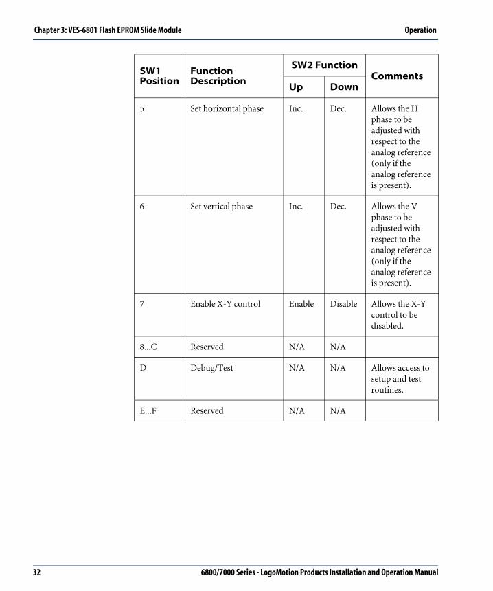
Chapter 3: VES-6801 Flash EPROM Slide Module Operation
5 Set horizontal phase Inc. Dec. Allows the H phase to be adjusted with respect to the analog reference (only if the analog reference is present).
6 Set vertical phase Inc. Dec. Allows the V phase to be adjusted with respect to the analog reference (only if the analog reference is present).
7 Enable X-Y control Enable Disable Allows the X-Y control to be disabled.
8...C Reserved N/A N/A
D Debug/Test N/A N/A Allows access to setup and test routines.
E...F Reserved N/A N/A
SW1 Position
Function Description
SW2 FunctionComments
Up Down
32 6800/7000 Series - LogoMotion Products Installation and Operation Manual

Operation Chapter 3: VES-6801 Flash EPROM Slide Module
LED IndicatorsThe VES-6801 has the following LED indicators:
There is also an internal “configuration failed” LED that flashes during power up and remains illuminated if the VES module exhibits a hardware failure upon powering up.
Label Description
525 Standard of the slide currently played.
625 Standard of the slide currently played.
Lock Indicates that the module is locked to external reference.
Write Indicates that the module is in write mode.
Operate Indicates the module is in normal operation.
Slide 1 Indicates that Slide 1 (Channel A) is being played.
Slide 2 Indicates that Slide 2 (Channel A) is being played.
Slide 3 Indicates that Slide 3 (Channel B) is being played.
Slide 4 Indicates that Slide 4 (Channel B) is being played.
The above indicator is set by playing the slide in Channel A.
6800/7000 Series - LogoMotion Products Installation and Operation Manual 33

Chapter 3: VES-6801 Flash EPROM Slide Module Operation
Figure 3-1. VES-6801 Serial Flash Slide
MO
DE
SE
LEC
TS
WITC
HT
OG
GLE
SW
ITCH
PO
SFU
NC
TION
DO
WN
UP
01234567D
OP
ER
ATE
SLID
E A
SLID
E B
GP
I AG
PI B
HO
RZ P
HV
ER
T P
HE
N X-Y
TE
ST
INC
INC
LEV
LEV
INC
INC
OFF
DE
CD
EC
ED
GE
DG
DE
CD
EC
ON
7000FR
AM
ES
RS
232TO
BN
C
GP
ITO
BN
C
JUM
PE
RS
J2 J3
(A) VES-6801SERIAL FLASH SLIDE
R
SW2
SW1D1
D2D4
D6
D3
D5
D8
D9
D7SLIDE 1
SLIDE 2SLIDE 3
SLIDE 4
525625
LOCK
WRITEOPER
DO
WN
BOARD IDJ1
J2
1
2
4
8
J3
J4
(NOTE: J5 is located at thetop right corner of the card.)
34 6800/7000 Series - LogoMotion Products Installation and Operation Manual

Operation Chapter 3: VES-6801 Flash EPROM Slide Module
JumpersThere are four jumper blocks, as described below.
Set jumpers J2 and J3 to the following positions if necessary:
1. GPI-in B/GPI-Out to BNC 5 and 7
2. Set for RS232 to BNC 5 and 7
Jumper Description
J1 Used to specify the Board ID for use with the Logo/Slide control system.
J2 and J3 Selects either GPI-InB and GPI-Out or RS232 Tx/Rx to be routed to BNC 5 and 7 on the 6800 frame.
J4 The write-protect jumper. When in the PROTECT position, writing to the flash memory is inhibited.When in the WRITE position, writing to the flash memory is allowed.
J5 Terminates the reference input to 75Ω.
J2 J3
Front of Unit
J2 J3
Front of Unit
6800/7000 Series - LogoMotion Products Installation and Operation Manual 35

Chapter 3: VES-6801 Flash EPROM Slide Module Operation
3. VES-6801-BM Back Module installed in a 7000 series frame (to allow both RS232 and GPI/GPO to output to the rear DB9 and screw terminal connectors).
Connectors The 6801 module can be installed in a 6800 series frame using rear BNC connectors, or in a 7000 series frame using the VES-6801-BM dedicated Back Module rear box. See the “Back Module and Overlay” below.
Figure 3-2. VES-6801 Back Module and Overlay
J2 J3
Front of Unit
B/RS232 TX and Out/RS232 RX are selectable by jumpers on the card.
VES-6801REF
IN
SERIAL OUT
A2
B2
A1
B1
GPI In B/RS232 Tx
Out/RS232 Rx
X-Y
In A
VES-6801-M
SERIAL OUTA2B2 A1B1
RS232GPI-I GPI-O
GND A B 1 GND
X-Y
This module is used when the VES-6801 module is installed into either a MIX-7001 series or FR-7000MB MIX BOX frame.
This overlay is used when the VES-6801 module is installed into a 6800 series frame.
36 6800/7000 Series - LogoMotion Products Installation and Operation Manual
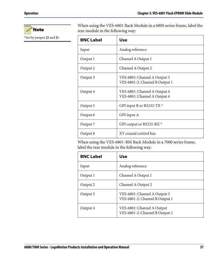
Operation Chapter 3: VES-6801 Flash EPROM Slide Module
When using the VES-6801 Back Module in a 6800 series frame, label the rear module in the following way:
When using the VES-6801-BM Back Module in a 7000 series frame, label the rear module in the following way:
BNC Label Use
Input Analog reference
Output 1 Channel A Output 1
Output 2 Channel A Output 2
Output 3 VES-6801: Channel A Output 3VES-6801-2: Channel B Output 1
Output 4 VES-6801: Channel A Output 4VES-6801: Channel A Output 4
Output 5 GPI input B or RS232-TX *
Output 6 GPI input A
Output 7 GPI output or RS232-RX *
Output 8 XY coaxial control bus
BNC Label Use
Input Analog reference
Output 1 Channel A Output 1
Output 2 Channel A Output 2
Output 3 VES-6801: Channel A Output 3VES-6801-2: Channel B Output 1
Output 4 VES-6801: Channel A Output VES-6801-2: Channel B Output 2
*Set by jumper J2 and J3.
6800/7000 Series - LogoMotion Products Installation and Operation Manual 37

Chapter 3: VES-6801 Flash EPROM Slide Module Operation
GPIThe slide selection is updated at the end of the EAV on line 10.
This update is transparent if both slides are the same standard.
RS232 • 9-pin D-sub female
• Pin 1: DCD-unused
• Pin 2: TxD
• Pin 3: RxD
• Pin 4: DTR-unused
• Pin 5: GND/0V
• Pin 6: DSR -|
• Pin 7: RTS-|
• Pin 8: CTS -|
• Pin 9: RI-unused
GPI-I/O • 5 position terminal block
• Terminal 1: GND
• Terminal 2: GPI-InA
• Terminal 3: GPI-InB
• Terminal 4: GPI-Out
• Terminal 5: GND
BNC Label Use
BNC Label Use
GPI-InA Selects the slide on Channel A.
GPI-InB Selects the slide on Channel B.
GPI-OUT Closes to GND during the slide download to indicate that there is no valid serial output.
38 6800/7000 Series - LogoMotion Products Installation and Operation Manual

Operation Chapter 3: VES-6801 Flash EPROM Slide Module
Test PointsThe table below shows the Test Points that are available for troubleshooting:
Label Description
TP1 GND (0V)
TP2 Vpp set to +4.90 V (approximately) when writing to flash memory (only when write enabled and in download).
TP3 +5 V
TP4 TPB used with TPA to measure current from the +5 V supply.
TP5 TPA used with TPB to measure current from the +5 V supply.
TP6 PLL UP PLL control pulses (positive going) *.
TP7 PLL DOWN control pulses (negative going) *.
TP8 GND (0 V)
TP9 External Horizontal (H) pulse derived from the external reference *.
TP10 External Vertical (V) pulse derived from the external reference *.
TP11 External Field (F) pulse derived from the external reference *.
*External reference must be present.
6800/7000 Series - LogoMotion Products Installation and Operation Manual 39

Chapter 3: VES-6801 Flash EPROM Slide Module Operation
Slide DownloadThe standard of operation (525/60 or 625/50) and the slide resolution (8-bit or 10-bit) are set by the downloaded slide. The module can only operate in one resolution and one standard at a time.
For the VES-6801 single-channel module, this means that two 8-bit slides can be stored with different standards, and when played back, the output will follow the standard of the selected slide. In 10-bit resolution, only one slide can be stored, and dual-standard is not an option.
For VES-6801-2 dual-channel modules, both channels must be in the same standard and resolution.
Creating, Recording and Downloading SlidesCustomer-designed logos (slides) may be loaded into the VES-6801 via the LogoMotion Graphics Conversion and Download Utility. This Utility loads the custom-created files from a computer via a serial port. The VES-6801 module creates and embeds the EAV, SAV, and EDH data packets after the graphic is loaded.
Terminology
The download operation uses either LogoDOS or LogoWIN. These are generic applications that refer to “logo”, which is synonymous with “slide.” If there are two outputs available, they are as follows:
Slides can only be played back at the standard for which they were created. If the external reference does not match the slide standard, the output will not be genlocked. If slides of different standards are stored, the module standard is set by Channel A.Playing slides of different standards on Channel B will result in erroneous data.
Refer to Chapter 1 of this manual for more information.
In 8-bit mode Slides 1 and 2 are visible only to Output A.Slides 3 and 4 are visible only to Output B.
In 10-bit mode Slide 1 is visible only to Output A.Slide 2 is visible only to Output B.
A slide must be loaded before valid data can be output. The VES-6801 uses data embedded in the file to generate valid timing information (SAV/EAV). The serial waveform may appear normal before the slide download, but it is not valid until download is complete. During download, the serial outputs are muted.
40 6800/7000 Series - LogoMotion Products Installation and Operation Manual
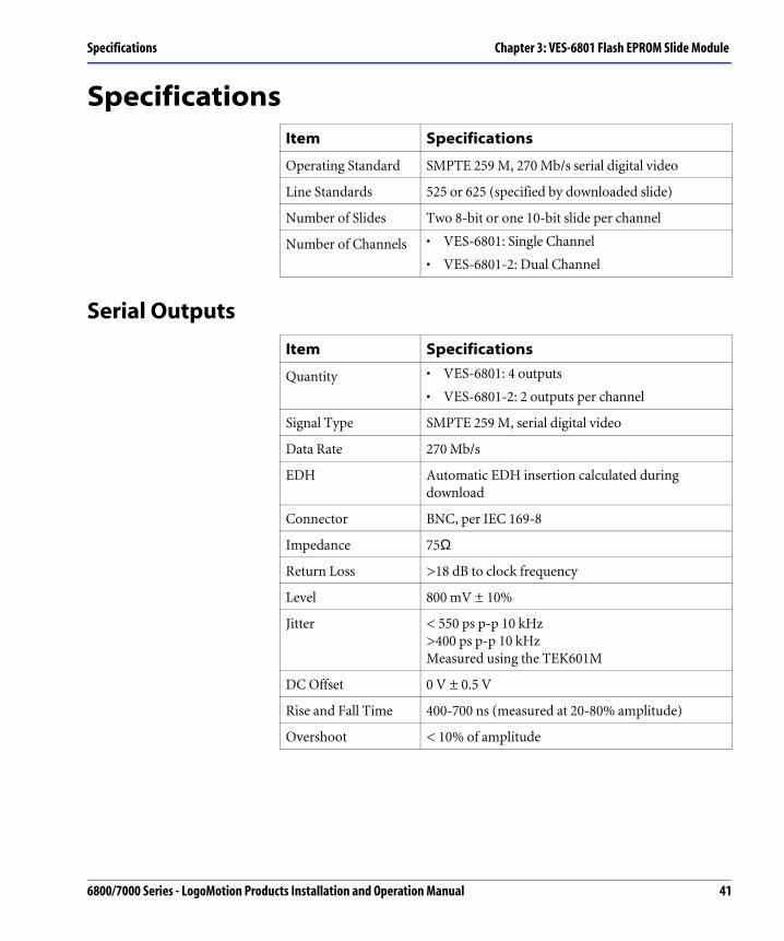
Specifications Chapter 3: VES-6801 Flash EPROM Slide Module
Specifications
Serial Outputs
Item Specifications
Operating Standard SMPTE 259 M, 270 Mb/s serial digital video
Line Standards 525 or 625 (specified by downloaded slide)
Number of Slides Two 8-bit or one 10-bit slide per channel
Number of Channels • VES-6801: Single Channel
• VES-6801-2: Dual Channel
Item Specifications
Quantity • VES-6801: 4 outputs
• VES-6801-2: 2 outputs per channel
Signal Type SMPTE 259 M, serial digital video
Data Rate 270 Mb/s
EDH Automatic EDH insertion calculated during download
Connector BNC, per IEC 169-8
Impedance 75Ω
Return Loss >18 dB to clock frequency
Level 800 mV ± 10%
Jitter < 550 ps p-p 10 kHz >400 ps p-p 10 kHz Measured using the TEK601M
DC Offset 0 V ± 0.5 V
Rise and Fall Time 400-700 ns (measured at 20-80% amplitude)
Overshoot < 10% of amplitude
6800/7000 Series - LogoMotion Products Installation and Operation Manual 41

Chapter 3: VES-6801 Flash EPROM Slide Module Specifications
Analog Reference
Control
Power Requirements
Item Specifications
Signal Type Composite sync or composite video
Impedance 75Ω or high impedance
Input Level Composite sync: 0.2 V to 4 VComposite video: 0.6 V to 2 V
Item Specifications
GPI Input # 1 Selects slide on Channel A
GPI Input # 2 Selects slide on Channel B(only for VES-6801-2)
GPI Output • Open Collector pull-down during download
• Maximum Current: 100 mA
• Maximum Voltage: 10 V
RS232 Serial Port available as DB9 on front of card, or dual BNC connectors on rear of unit
• 38,400 baud
• 1 stop bit
• no parity
Protocol Leitch Logo Generator protocol
XY Bus BNC available on rear of unit, high impedance
Protocol Leitch Logo Generator protocol
Item Specifications
VES-6801 Positive rail: 3.0 WNegative rail: 1.5 WTotal: 4.5 W
VES-6801-2 Positive rail: 4.9 WNegative rail: 1.5 WTotal: 4.5 W
42 6800/7000 Series - LogoMotion Products Installation and Operation Manual

Chapter 4
DSK-6801/3 Downstream Serial Keyer
OverviewThe Downstream Serial Keyers (DSK) 6801 and 6803 are designed to meet the need for the insertion of high-quality key signals in today’s busy production and post production facilities. The production market is demanding increasing numbers of key insertions into program video, and the DSK-6801 and DSK-6803 are important supplements to the limited keying capability of current production switchers.
The DSK-6801/3 modules are standalone serial digital keyers with a full complement of features, many of which are found on high-end production switchers. Some of the features offered by both the DSK-6801 and the DSK-6803 include:
• Support of a 270 Mb/s 525/625 program and Fill/Key input signals. All inputs auto time, with approximately ± one-half line timing buffers.
• Error Detection Handling (EDH) on inputs and EDH insertion on the program output.
• A 10-bit program path, coupled to 12-bit internal keyers, to provide optimum quality.
• Passing of all ancillary data present in the program path. (Any embedded audio is also passed, uninterrupted.)
• Ability to use the Keyer in A/B Background Transition (Roll) mode, without keys. In this mode, the Fill path is used as a second background (B), to be wiped or faded from the program channel (A)DSK-6801 Keyer features.
Specifications and designs are subject to change without notice.
6800/7000 Series - LogoMotion Products Installation and Operation Manual 43

Chapter 4: DSK-6801/3 Downstream Serial Keyer Overview
DSK-6801 Keyer FeaturesThe DSK-6801 Downstream Serial Keyer offers the following features:
• Luminance (Self-Key), or linear keying using the Key signal
• Mix mode keying
• Key masking
• Adjustable transparency, gain, and offset
• Adjustable fade rates
• Fade-to-black control
• GPI control
• XY interface for connection to a remote panel
• EDH checking of program input
• EDH CRC generation on program output
• Optional compact remote control
Figure 4-1. DSK-6801 Block Diagram and Control Logic
Reclock& S/P
EDHDetect
MatteGenerator
Auto HTiming
DigitalLinear Fader
EDHInsert
Self Key
AutoEQ
Auto HTiming
Auto HTiming
Reclock& S/P
Reclock& S/P
DigitalLinear Fader
AutoEQ
AutoEQ
FADE
ProgramOutProgram
In
Fill In
Key in
Control Logic
Ext Ref XYRemote
RS232Control
44 6800/7000 Series - LogoMotion Products Installation and Operation Manual

Overview Chapter 4: DSK-6801/3 Downstream Serial Keyer
DSK-6803 Keyer FeaturesThe DSK-6803 has all of the same features as the DSK-6801 with the following additions:
• Preview path, allowing viewing of keyed output before going to air
• Additive keying mode
• Chroma keying, with selectable hue, discrimination, and saturation
• Easy wipe Left, Right, Up and Down transition
Figure 4-2. DSK-6803 Block Diagram and Control Logic
Reclock& S/P
EDHDetect
Auto HTiming
EDHInsert
ChromaControl
Digital LinearFader
Reclock& S/P
Reclock& S/P
Auto HTiming
Auto HTiming
DigitalAdditive +
Linear Keyer
MatteGenerator Program
Out
PreviewOut
ProgramIn
Fill In
Key In
Wipe/Fade
Self Key Chroma Key
AutoEQ
AutoEQ
AutoEQ
Control Logic
Ext Ref XYRemote
RS232Control
6800/7000 Series - LogoMotion Products Installation and Operation Manual 45

Chapter 4: DSK-6801/3 Downstream Serial Keyer Installing and Setup
Installing and Setup
System Setup ConsiderationsThe items in this section should be read and implemented at the time of installation.
Standard Selection
The Keyer is equipped to:
• Force a given standard (either 525 or 625 lines).
• Allow the module to auto detect the incoming standard.
In sensitive applications the standard should be set to 525 or to 625. Make sure the appropriate line rate is always selected.
Lock Source
There are two modes of locking the Keyer to the given sources:
1. Lock to the incoming PGM input.
The operator can only adjust horizontal timing toward minimum length or toward one full line length in delay.
2. Lock to an external analog reference.
In this mode, both horizontal and vertical timing adjustments are available. Adjusting the Keyer timing for proper Keyer operation compensates for the relative difference between reference V and program V.
46 6800/7000 Series - LogoMotion Products Installation and Operation Manual

Installing and Setup Chapter 4: DSK-6801/3 Downstream Serial Keyer
Keyer Timing
Keyer timing is derived from the lock source. The lock source can be either the PGM input or the external analog reference.
Using the PGM input as the lock source, Keyer timing operates with the Keyer set to one half line delay, with the Fill and Key inputs autotimed from within ± one half line. The Fill and Key inputs are automatically adjusted to fit within the timing window. This selection allows the timing to be adjusted as follows:
• Minimum timing can be adjusted by reducing the Horizontal phase towards zero. Make sure after adjustment that the Fill and Key inputs still fall within the timing window. See “Position 5: SW2 System Horizontal Timing” on page 75.
• Using the external analog reference as the lock source, keyer timing operates in much the same way as when locked to PGM input. The main difference is that both the horizontal and vertical timing can be adjusted. See “Position 5: SW3 System Vertical Timing” on page 75.
• In the external analog Reference mode, the delay of the video signal may be a concern. If so, the delay can be adjusted toward a full line.
• If Key and Fill fall beyond the timing window, the keying operation is not usually allowed. To override this function, set the Sync Detection to Off. See “Position 7: SW3 Sync Detection” on page 77.
To aid the timing alignment, the operator should use the auto timing function to phase the internal timing to the program Key and Fill serial videos. The timing is varied for both horizontal and vertical, so all three inputs (Program, Key, and Fill) are within the one-line window. If the input signals are spread over more than one line and alignment is not possible, an error is displayed and the sources must be corrected externally. See “DSK-CP1/2 Downstream Serial Keyer Control Panel” table on page 91.
Multiple Keyer Control/Group ID
The DSK-CPx uses the Group ID function to control multiple Keyers. Each Keyer is set up with an individual address (Keyer ID) and can then be configured to work using Group IDs, controlled by the DSK-CPx.
You may need to set different Group IDs, depending on how the network layout and module control is handled. See “DSK-CP1/2 Downstream Serial Keyer Control Panel” on page 91.
An error is displayed if Key or Fill are beyond the timing range. See “Error LEDs” table on page 53.
6800/7000 Series - LogoMotion Products Installation and Operation Manual 47
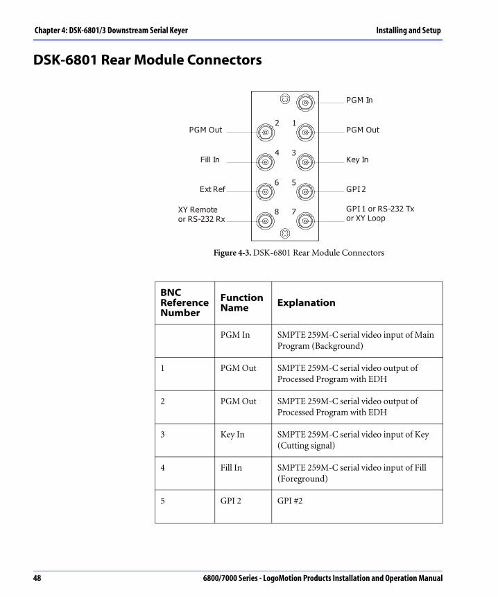
Chapter 4: DSK-6801/3 Downstream Serial Keyer Installing and Setup
DSK-6801 Rear Module Connectors
Figure 4-3. DSK-6801 Rear Module Connectors
BNCReference Number
FunctionName Explanation
PGM In SMPTE 259M-C serial video input of Main Program (Background)
1 PGM Out SMPTE 259M-C serial video output of Processed Program with EDH
2 PGM Out SMPTE 259M-C serial video output of Processed Program with EDH
3 Key In SMPTE 259M-C serial video input of Key (Cutting signal)
4 Fill In SMPTE 259M-C serial video input of Fill (Foreground)
5 GPI 2 GPI #2
XY Remoteor RS-232 Rx
PGM In
PGM Out
Key In
GPI 2
GPI 1 or RS-232 Tx or XY Loop
PGM Out
Fill In
Ext Ref
2 1
4 3
6 5
8 7
48 6800/7000 Series - LogoMotion Products Installation and Operation Manual

Installing and Setup Chapter 4: DSK-6801/3 Downstream Serial Keyer
6 Ext Ref External Reference
7 GPI 1 orRS-232 Tx orXY Loop
GPI #1 or RS-232 automatic control transmission in or XY remote panel loop-through
8 XY Remote orRS-232 Rx
XY remote serial data control or RS-232 automatic control reception line
BNCReference Number
FunctionName Explanation
6800/7000 Series - LogoMotion Products Installation and Operation Manual 49

Chapter 4: DSK-6801/3 Downstream Serial Keyer Installing and Setup
DSK-6803 Rear Module Connectors
Figure 4-4. DSK-6803 Rear Module Connectors
BNC Reference Number
Function Name Explanation
PGM In SMPTE 259M-C serial video input of Main Program (Background)
1 PGM Out SMPTE 259M-C serial video output of Processed Program with EDH
2 PGM Out SMPTE 259M-C serial video output of Processed Program with EDH
3 KEY In SMPTE 259M-C serial video input of Key (Cutting signal)
4 FILL In SMPTE 259M-C serial video input of Fill (Foreground)
5 GPI 2 orP/V
GPI # 2 (Jumper configuration) orPreview Output
XY Remoteor RS-232 Rx
PGM In
PGM Out
Key In
GPI 2
GPI 1 or RS-232 Tx or XY LoopExt Ref
PGM Out
Fill In
Ext Ref
2 1
4 3
6 5
8 7
50 6800/7000 Series - LogoMotion Products Installation and Operation Manual

Installing and Setup Chapter 4: DSK-6801/3 Downstream Serial Keyer
6 P/V Preview Output
7 GPI 1 orRS-232 Tx or XY Loop or Ext Ref
GPI # 1 or RS-232 automatic control transmission line or XY remote panel loop-through orexternal analog sync reference input
8 XY Remote orRS-232Rx
XY remote serial data control (Jumper configuration) or RS-232 automatic control (jumper configuration) orRS-232 automatic control reception line
BNC Reference Number
Function Name Explanation
6800/7000 Series - LogoMotion Products Installation and Operation Manual 51
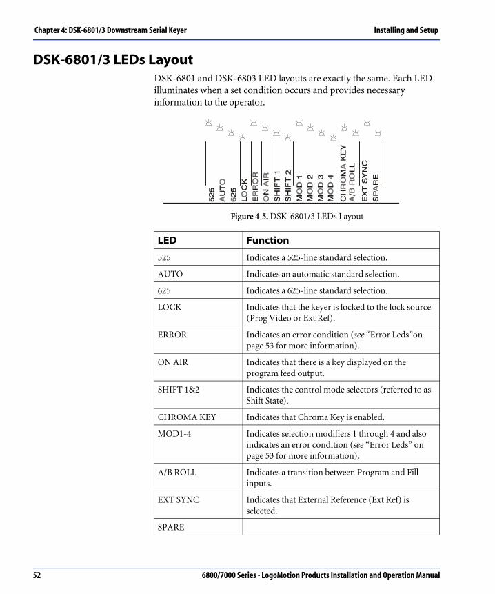
Chapter 4: DSK-6801/3 Downstream Serial Keyer Installing and Setup
DSK-6801/3 LEDs LayoutDSK-6801 and DSK-6803 LED layouts are exactly the same. Each LED illuminates when a set condition occurs and provides necessary information to the operator.
Figure 4-5. DSK-6801/3 LEDs Layout
LED Function
525 Indicates a 525-line standard selection.
AUTO Indicates an automatic standard selection.
625 Indicates a 625-line standard selection.
LOCK Indicates that the keyer is locked to the lock source (Prog Video or Ext Ref).
ERROR Indicates an error condition (see “Error Leds”on page 53 for more information).
ON AIR Indicates that there is a key displayed on the program feed output.
SHIFT 1&2 Indicates the control mode selectors (referred to as Shift State).
CHROMA KEY Indicates that Chroma Key is enabled.
MOD1-4 Indicates selection modifiers 1 through 4 and also indicates an error condition (see “Error Leds” on page 53 for more information).
A/B ROLL Indicates a transition between Program and Fill inputs.
EXT SYNC Indicates that External Reference (Ext Ref) is selected.
SPARE
52 6800/7000 Series - LogoMotion Products Installation and Operation Manual
Installing and Setup Chapter 4: DSK-6801/3 Downstream Serial Keyer
Error LEDs
The Error LED illuminates an error condition and, combined with the MOD1-4 LED indicators, produces an error status pattern (or error code). This produces a definable status, which prompts the operator to locate and correct error conditions.
BNC Selection, Jumper Setup, and Switch SetupBNC selection, jumpers, and switches are set at the time of installation and adjusted as necessary. The following describes the BNC selection options as well as jumper and switch setting options for both the DSK-6801 and the DSK-6803.
BNC Selection
To make BNC setup easier, the connector numbers shown on the rear modules are also used as reference numbers in tables and figures. See and “DSK-6803 Rear Module Connectors” table on page 50 for examples of how the connector numbers are used.
Error LED Indicator
Fill Lock MOD3
Key Lock MOD# and MOD4
Timing MOD2
EDH MOD2 and MOD4
The module must be in Shift 0, and the Hex Switch at 0 positionto check the Error LEDs.
The timing error indicates that the timing of Program, Key or Fill is off. To determine which of these is out of timing, go to the Timing position (Shift 2, Hex position 5 or 6) and check which LEDs are illuminated.
6800/7000 Series - LogoMotion Products Installation and Operation Manual 53
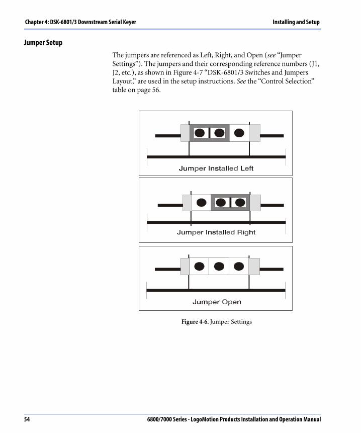
Chapter 4: DSK-6801/3 Downstream Serial Keyer Installing and Setup
Jumper Setup
The jumpers are referenced as Left, Right, and Open (see “Jumper Settings”). The jumpers and their corresponding reference numbers (J1, J2, etc.), as shown in Figure 4-7 “DSK-6801/3 Switches and Jumpers Layout,” are used in the setup instructions. See the “Control Selection” table on page 56.
Figure 4-6. Jumper Settings
54 6800/7000 Series - LogoMotion Products Installation and Operation Manual

Installing and Setup Chapter 4: DSK-6801/3 Downstream Serial Keyer
Switches
The switches are set in conjunction with the jumpers. The setup options given below are for both the DSK-6801 and the DSK-6803 unless otherwise noted.
Figure 4-7. DSK-6801/3 Switches and Jumpers Layout
Group ID Selection
SW4 is used to select the Group ID for external control by the DSK-CPx.
Switch Function
SW1 Hex function control selector Switch 1 (SW1) controls settings zero to F (0 - F).
SW2 Parameter modification toggle (up/down) Switch 2 (SW2).
SW3 Parameter modification toggle (up/down) Switch 3 (SW3).
SW4 Group ID Switch 4 (SW4) selects the Group ID for external control by the DSK-CPx.
6800/7000 Series - LogoMotion Products Installation and Operation Manual 55

Chapter 4: DSK-6801/3 Downstream Serial Keyer Installing and Setup
Control SelectionThe Control Selections for GPI 1, GPI 2, XY loop-through, and RS232 are shown below. The use of Ext Ref Sync on BNC 7 removes RS232, GPI 1, and XY loop-through capability. For a list of the mutually exclusive settings, see the table below.
Control Settings
XY (on BNC 8) and GPI 1 (BNC 7) Selection
J4 Right XY selection
J6 Right GPI 1 selection
J7 Right GPI 1 selection
J3 Right XY open termination, HIZ
J3 Left XY termination at 75 Ω
XY Loop-Through Selection on BNC 7 and BNC 8
J3 Right HIZ termination for loop-through
J4 Right Selects XY
J7 Left Selects loop-through
RS232 Selection
J4 Left RS232 Rx selection
J6 Left RS232 Tx selection
J7 Right RS232 Tx selection
J8 Left HIZ
GPI 2 or P/V on BNC 5 (for DSK-6803 only)
J5 Left P/V
J5 Right GPI 2
The RS232 port is reserved for future control expansion.
56 6800/7000 Series - LogoMotion Products Installation and Operation Manual

Installing and Setup Chapter 4: DSK-6801/3 Downstream Serial Keyer
External Sync Reference Selection
On the DSK-6801, Ext Sync Ref is always on BNC 6 without the use of jumpers. For DSK-6803 to select External Sync Ref to BNC 7, set the following:
External Sync Reference Termination
Keyer Module ControlsThe DSK-6801/3 modules have the following control mechanisms:
• Front edge control
• GPI control
• DSK CP control
Adjusted parameters are only stored after 5 seconds of inactivity.
Front Edge Control
Front edge control is accomplished using Hex Switch SW1 and Toggle Switch SW2 to select one of three possible Shift States (Shift State 0, 1, and 2). Each Shift State provides access for up to 15 different control/setup options. Upon powering up, the module is automatically set to Shift State 0. Shift State 1 and 2 are accessed as follows:
1. Move SW1 to Position 0.
2. Toggle SW2 up or down to achieve the desired Shift State.
The Shift State LEDs on the front edge of the module indicate the current Shift State setting. For example, when Shift 1 LED is illuminated, the module is in Shift State 1. Shift State 0 has no LED indicator. See Figure 4-5 on page 52 for more information.
J6 Open
J7 Right
Change of external sync level from 300 mV to 4 V is available through the main hex switch. See “Front Edge Control” table on page 57 for more information.
J8 Right, for 75 Ω
J8 Left, or open, for HIZ
In Hex Position 0, when a Shift State is inactive for approximately 30 seconds, the module is automatically timed out and reset to Shift State 0.
6800/7000 Series - LogoMotion Products Installation and Operation Manual 57

Chapter 4: DSK-6801/3 Downstream Serial Keyer Installing and Setup
The following tables are provided to illustrate the functionality of the Shift States. Each Shift State table shows SW1 positions with the SW2 and SW3 corresponding actions.
In the following tables, non-shaded sections apply to DSK-6801 and DSK-6803. Shaded sections are DSK-6803 extensions only.
Shift State 0-General Functions
Using edge control may delay remote control updates of control status during use.
SW1 Position SW2 Action SW3 Action
0 Shift (Shift 1/Shift 2) Not used
1 Key Offset Inc/Dec Not used
2 Key Gain Inc/Dec Not used
3 Key Transparency Inc/Dec Not used
4 Key Source (Self/Normal/AB Roll/Chroma Key)
Key Invert On/Off
5 Key Mask On/Off Key Mask Invert On/Off
6 Key Mask, Top Edge Out/In Key Mask, Bottom Edge Out/In
7 Key Mask, Left Edge Out/In Key Mask, Right Edge Out/In
8 Not used Key Force
9 Additive Key On/Off Not used
A FTB Fade Rate Inc/Dec Not used
B Fade To Black On/Off Cut To Black On/Off
C Not used Not used
58 6800/7000 Series - LogoMotion Products Installation and Operation Manual

Installing and Setup Chapter 4: DSK-6801/3 Downstream Serial Keyer
D Reserved Not used
E Set Key Fade Rate Inc/Dec Not used
F Fade Key On/Off Cut Key On/Off
SW1 Position SW2 Action SW3 Action
See “Settings for Shift State 0: General Functions” table on page 62 for more information.
6800/7000 Series - LogoMotion Products Installation and Operation Manual 59

Chapter 4: DSK-6801/3 Downstream Serial Keyer Installing and Setup
Shift State 1–Extended Functions
SW1Position SW2 Action SW3 Action
0 Shift (Shift 2/Shift 0) Not used
1 Wipe/Fade Select Not used
2 Pattern Select Not used
3 Wipe Direction Wipe Direction Invert
4 Not used Not used
5 Not used Not used
6 Chroma Hue Not used
7 Chroma Saturation Not used
8 Chroma Discrimination Not used
9 Not used Not used
A Not used Not used
B Not used Not used
C Not used Not used
D Not used Not used
E Not used Not used
F Not used Not used
For more Information see “Settings for Shift State 1: Extended Setup” table on page 68 for more information.
60 6800/7000 Series - LogoMotion Products Installation and Operation Manual

Installing and Setup Chapter 4: DSK-6801/3 Downstream Serial Keyer
Shift State 2–System Configurations
SW1Position SW2 Action SW3 Action
0 Shift (Shift 0/Shift 1) Not used
1 GPI 1 Action - Input or Tally GPI 1 Type - Input or Tally
2 GPI 2 Action - Input or Tally GPI 2 Type - Input or Tally
3 GPI 3 Action - Input or Tally GPI 3 Type - Input or Tally
4 GPI 4 Action - Input or Tally GPI 4 Type - Input or Tally
5 System Horizontal Timing Inc/Dec System Vertical Timing Inc/Dec
6 System Field Timing Inc/Dec Auto System Timing
7 Set Standard (525/Auto/625) Sync Detection On/Off
8 External Sync Type 300 mV/4 V External/Program Sync Select
9 Mask Reset Not used
A Not used Not used
B Keyer ID (Upper) Not used
C Keyer ID (Lower) Not used
D Reserved Not used
E Not used Not used
F Recall Factory Default Key Settings Recall Factory Default System Settings
See “Settings for Shift State 2: Configuration” table on page 71 for more information.
6800/7000 Series - LogoMotion Products Installation and Operation Manual 61

Chapter 4: DSK-6801/3 Downstream Serial Keyer Installing and Setup
Settings for Shift State 0: General FunctionsThis section gives a more complete description of the Keyer Module controls for Shift State 0. It is organized by Hex Switch Positions (Position 1, 2, etc.). Shift Hex Position 0 is not included in the following listing since its function never changes.
Position 1: SW2 Key Offset
Key Offset (incremental/decremental) varies between 0 and 1024 with the standard being 64.
• Subtract the Offset (or Clip) value from the Key Input.
• Push SW2 up to increase the Key Offset.
• Push SW2 down to decrease the Key Offset.
• Set Key Offset to 0 with a gain of 16 to display Key full on screen with no program.
Position 2: SW2 Key Gain
Key Gain varies between 0.5 and 64 times.
• Multiply the Gain value by the Key Input and combine with the Offset to get the actual Key.
• Push SW2 up to increase the Gain value.
• Push SW2 down to decrease the Gain.
Position 3: SW2 Key Transparency
Key Transparency varies between 0% and 100%.
• Set the transparency to 100% to fully apply the selected Gain and Offset.
• Set the Transparency to zero (0%) so nothing is keyed to the output.
• Push SW2 up to increase Transparency.
• Push SW2 down to decrease the Transparency.
Position 1: SW# is not used.
Position 2: SW3 is not used.
Position 3: SW3 is not used.
62 6800/7000 Series - LogoMotion Products Installation and Operation Manual

Installing and Setup Chapter 4: DSK-6801/3 Downstream Serial Keyer
Position 4: SW2 Key Source
Key Source indicates whether the Key signal should be taken from the external Key Input (Normal) or extracted from the Fill Input luminance (Y) signal (Self).
• In A/B Roll mode, the Key signal is ignored, and the program can be faded or wiped to Fill and back again for program changes.
• In Chroma Key mode, the Key is derived from the color components of the Fill.
• Toggling SW2 cycles through the selections available.
• LED indication:
Position 4: SW3 Key Invert
Key Invert takes an inverted version of the Key Input to perform the keying. The effect of this is the same as subtracting the Key from the maximum white value (i.e. black where the input is white and vice versa).
• Push the SW3 up to activate.
• Push the SW3 down to deactivate.
• LED indication:
MOD1 External
MOD2 Self
A/B Roll A/B Roll mode
Chroma Key Chroma Key mode
In A/B Roll mode, Keyer parameters can be adjusted but have no effect as the Key signal is ignored.
MOD3 Invert Off
MOD4 Invert On
6800/7000 Series - LogoMotion Products Installation and Operation Manual 63

Chapter 4: DSK-6801/3 Downstream Serial Keyer Installing and Setup
Position 5: SW2 Key Mask On/Off
The Key Mask overrides the Key signal in the area outside where it is placed.
• Push the SW2 up to activate the Key Mask.
• Push the SW2 down to select the Off function.
• LED indication:
Position 5: SW3 Key Mask Invert
Mask Invert applies a mask everywhere except the area covered by the existing mask.
• Push the SW3 up to select the Key Mask Invert On.
• Push the SW3 down to select the Off function.
• LED indication:
Position 6: SW2 Key Mask, Top Edge
Key Mask, Top Edge Out/In is adjusted using SW2.
Push SW2 up or down for top vertical adjustments.
Position 6: SW3 Key Mask, Bottom Edge
Key Mask Bottom Edge Out/In is adjusted using SW3.
Push SW3 up or down for bottom vertical adjustments.
Position 7: SW2 Key Mask, Left Edge
Key Mask Left Edge Out/In is adjusted using SW2, for left horizontal adjustments.
Position 7: SW3 Key Mask, Right Edge
Key Mask Right Edge Out/In is adjusted using SW3, for right horizontal adjustments.
MOD1 Mask Off
MOD2 Mask On
MOD3 Mask Invert Off
MOD4 Mask Invert On
64 6800/7000 Series - LogoMotion Products Installation and Operation Manual

Installing and Setup Chapter 4: DSK-6801/3 Downstream Serial Keyer
Position 8: SW3 Key Force
This position sets the Key Mask into Force mode. This means the masked area is forced to be fully On. Normal mode is Off.
• Push the SW3 down to select On (forced mode enabled).
• Push the SW3 up to select Off.
The Force Key can be applied when the mask is Off.
• LED indication:
Position 9: SW2 Additive Key
The Additive Key selection puts the Keyer into an Additive Key mode. The Key cuts a hole into Program, and Fill is added to Result.
• Push the SW2 up to select the On position.
• Push the SW2 down to select the Off position.
• LED indication:
MOD3 Normal mode (Mask)
MOD Force mode
MOD1 Normal (Mix) Key
MOD2 Additive Key
Position 9: SW3 is not used.
Position 8: SW2 is not used.
6800/7000 Series - LogoMotion Products Installation and Operation Manual 65

Chapter 4: DSK-6801/3 Downstream Serial Keyer Installing and Setup
Position A: SW2 FTB Fade Rate
The value indicates the number of frames a Fade To Black will take, the minimum being zero and maximum being 100 frames. The current rate is indicated on the LEDs.
• Push SW2 up to increase the FTB Fade Rate.
• Push SW2 down to decrease the FTB Fade Rate.
See the Transition Table below to determine the FTB Fade Rate.
Transition Rates
For example, if the rate is 35 frames, the MOD4 LED will be On and the MOD3 LED flashes. This continues as the rate is adjusted until it reaches 29 or 40 frames. The Fade Rate remains on the LEDs until the Hex Switch is turned (to a different position) or SW2 is adjusted.
Position B: SW2 Fade To Black
Push the SW2 up to activate Fade to Black.
Push the SW2 down to deactivate Fade to Black.
If the FTB is in transition, a Key Fade cannot be started. A Fade in the opposite direction will take effect.
Position A: SW3 is not used.
Transition Rate LEDs State
9 + MOD4 Flashing
19 + MOD4 On
29 + MOD3 Flashing
39 + MOD3 On
49 + MOD2 Flashing
59 + MOD2 On
69 + MOD1 Flashing
79 + MOD1 On
66 6800/7000 Series - LogoMotion Products Installation and Operation Manual

Installing and Setup Chapter 4: DSK-6801/3 Downstream Serial Keyer
Position B: SW3 Cut To Black
Push the SW3 up to activate Cut to Black.
Push the SW3 down to deactivate Cut to Black.
Position E: SW2 Set Key Fade Rate
Set Key Fade Rate is the rate at which the fade takes place. See “Control Settings” on page 56.
• Push SW2 up to increase the rate or down to decrease it.
• Push the SW2 up to activate the Fade Key.
• Push the SW2 down to deactivate the Fade Key.
The active function of the Fade Key is to fade the keyed video onto the PGM/Program output.
Deactivation causes the keyed video to fade Off.
If a Fade is already in progress, a Fade in the same direction has no effect; a Fade in the opposite direction will take effect.
When FTB is active (black is shown on PGM OUT), the Key Transition rate is ignored. Any Key Transitions performed while the output is black act as a Key Cut. Then the Fill may or may not be keyed depending on the Fade Key setting.
Position F: SW3 Cut Key
The Cut Key transitions the Key On or Off instantly. When in black (FTB is active), the Cut Key switch has the same function as the Fade Key switch and operates in the same manner.
Position C: SW3 is not used.Position D: SW2 is not used.Position D: SW3 is not used.
Position E: SW3 is not used.
6800/7000 Series - LogoMotion Products Installation and Operation Manual 67

Chapter 4: DSK-6801/3 Downstream Serial Keyer Installing and Setup
Settings for Shift State 1: Extended SetupThis section gives a more complete description of the Keyer Module controls for Shift State 1. It is organized by Hex Switch Positions (Position 1, 2, etc.). Shift Hex Position 0 is not included in the following listing since its function never changes.
Position 1: SW2 Wipe/Fade Select
The Key Transition Type Select is used to choose between Wipe or Fade Key Transitions. SW2 functions are Up = Wipe and Down = Fade. Wipe Transition Type is available only on the DSK-6803.
LED indication:
Position 2: SW2 Pattern Select
The Pattern Select function provides a selection of patterns used for a Wipe. The following table shows the LED indicators and their corresponding pattern. The graphics (see Figure 4-8 on page 69) illustrates the patterns available for selection. SW2 is used to toggle through the selections. Watch the LEDs to select the desired pattern.
MOD1 Key Transition Type is Wipe.
MOD2 Key Transition Type is Fade.
Position 1: SW3 is not used.
Position 2: SW3 is not used.
68 6800/7000 Series - LogoMotion Products Installation and Operation Manual

Installing and Setup Chapter 4: DSK-6801/3 Downstream Serial Keyer
Figure 4-8. Wipe Patterns
Position 3: SW2 Wipe Direction
Wipe Direction at Normal setting provides a Key Wipe Off, which occurs in the same direction as the Key Wipe On.
In the Normal/Reverse setting, the Wipe Off takes the opposite direction of the Wipe On.
The actual direction in which the Wipe moves is determined by the Pattern Select setting and the Wipe Invert setting.
SW2 functions are Up = Normal /Reverse and Down=Normal.
LED indication:
MOD1 MOD2 MOD3 MOD4 Pattern
On Off Off Off Double Vertical
Off On Off Off Double Horizontal
Off Off On Off Cross
Off Off Off On Box
Double Vertical Double HorizontalBox
MOD1 Normal
MOD2 Normal Reverse
6800/7000 Series - LogoMotion Products Installation and Operation Manual 69

Chapter 4: DSK-6801/3 Downstream Serial Keyer Installing and Setup
Position 3: SW3 Wipe Direction Invert
Wipe Pattern Direction Invert is used to reverse the Wipe Direction when set to Normal. In Normal/Reverse, this selection causes only the Wipe On to move in the reverse direction. Wipe Off will still function in the normal direction.
LED indication:
Position 6: SW2 Chroma Hue
Chroma Hue changes the color for chroma keying. Toggling the switch Up or Down changes the selected color.
Position 7: SW2 Chroma Saturation
Chroma Saturation changes the saturation of color for chroma keying.
Position 8: SW2 Chroma Discrimination
Chroma Discrimination controls the range of color for chroma keying. A high Chroma Discrimination setting provides a narrow range of color while a lower setting allows a wider range of color used to generate the Key signal.
MOD3 Pattern direction Invert Off
MOD4 Pattern direction Invert On
Position 5: SW2 is not used.Position 5: SW3 is not used.
Position 4: SW2 is not used.Position 4: SW3 is not used.
Position 6: SW3 is not used.
Position 7: SW3 is not used.
Position 8: SW3 is not used.
Position 9 through position F (SW2 and SW3 are not used).
70 6800/7000 Series - LogoMotion Products Installation and Operation Manual
Installing and Setup Chapter 4: DSK-6801/3 Downstream Serial Keyer
Settings for Shift State 2: ConfigurationThis section gives a more complete description of the Keyer Module controls for Shift State 2. It is organized by Hex Switch Positions (Position 1, 2, etc.). Shift Hex Position 0 is not included in the following listing since its function never changes.
Position 1: SW2 GPI 1 Action
The General Purpose Interface 1 (GPI 1) Action state allows the GPI Input behavior to be configured to Key Fade or Key Cut and FTB Fade or FTB Cut.
For the action of each of these settings and more details, see “GPI Control” on page 79.
Position 1: SW3 GPI 1 Type
GPI 1 Type can be configured as follows:
• Inputs: Rising Edge/Falling Edge/Active High /Active Low/Off.
• Tally: Tally High/Tally Low.
• GPI control settings are cycled through by toggling SW3 Up or Down.
• A GPI Input will perform the assigned action when the trigger is detected.
• A GPI Tally sets its output level to the assigned Tally Active Level when its trigger condition is in effect, and sets its output to the opposite level when the condition is not found.
• A Tally that acts on Key On will be active whenever the Key is even slightly On Air (similar to the behavior of the On AIR LED). This is the normal use for a Tally.
• A GPI can be assigned as an output to give a similar indication for Fade to Black.
• The Error Triggers are presented such that the Tally Output can indicate the error or feed a GPI Input (of another Keyer), which may be used to override the erroneous signal.
6800/7000 Series - LogoMotion Products Installation and Operation Manual 71

Chapter 4: DSK-6801/3 Downstream Serial Keyer Installing and Setup
GPI 1 Type LED indicators are described in the following table:
Type Trigger
Input Action or Tally Active Level
MOD LEDs
SW 2 SW 3
MOD1 MOD2 MOD3 MOD4
Off (Disabled)
None None Flashing Flashing
Output (Tally)
Key On Active High
On On Flashing On
Black On Off On
Any Error On Off
Program Error
Off Off
Key On Active Low
On On Flashing Off
Black On Off On
Any Error On Off
Program Error
Off Off
72 6800/7000 Series - LogoMotion Products Installation and Operation Manual

Installing and Setup Chapter 4: DSK-6801/3 Downstream Serial Keyer
Input High Level
Fade To Black
Off On On On
Cut To Black
Off Off
Auto Trans Key
On On
Cut Key On Off
Low Level Fade To Black
Off On On Off
Cut To Black
Off Off
Auto Trans Key
On On
Cut Key On Off
Rising Edge
Fade To Black
Off On Off On
Cut To Black
Off Off
Auto Trans Key
On On
Cut Key On Off
Type Trigger
Input Action or Tally Active Level
MOD LEDs
SW 2 SW 3
MOD1 MOD2 MOD3 MOD4
6800/7000 Series - LogoMotion Products Installation and Operation Manual 73

Chapter 4: DSK-6801/3 Downstream Serial Keyer Installing and Setup
The GPI 1 Type allows the GPI 1 to become active by a (configurable) detected level or edge.
The Active High setting allows the GPI to become active upon detection of a high level.
The Active Low setting allows the GPI to become active upon detection of a low level.
The GPI Tally can be configured as Tally High or Tally Low. The GPI state is toggled by the rising or falling edge of the input, as is typical behavior from a normally open, momentary closure push button.
The Off setting causes the GPI to be ignored and the LEDs to flash. Possible settings can be cycled through by toggling SW3 up or down.
Position 2: SW2 GPI 2 Action
GPI 2 Action and GPI 2 Type function in the same manner as GPI 1 Type and Action.
GPI 2 must be enabled through jumpers in order for these settings to take effect. See “BNC Selection, Jumper Setup, and Switch Setup” on page 53 for settings.
Position 2: SW3 GPI 2 Type
See GPI 1 Type above.
Falling Edge
Fade To Black
Off On Off Off
Cut To Black
Off Off
Auto Trans Key
On On
Cut Key On Off
Type Trigger
Input Action or Tally Active Level
MOD LEDs
SW 2 SW 3
MOD1 MOD2 MOD3 MOD4
74 6800/7000 Series - LogoMotion Products Installation and Operation Manual

Installing and Setup Chapter 4: DSK-6801/3 Downstream Serial Keyer
Position 3: SW2 GPI 3 Action & SW3 GPI 3 Type
Not available in this release.
Position 4: SW2 GPI 4 Action & SW3 GPI 4 Type
Not available in this release.
The next four positions (Positions 5 and 6) work in association with each other to adjust the Internal Timing to the three Input serial signals: Program, Fill, and Key. Normally, modifying the Vertical and Field Timing can cause unpredictable results and is only adjusted to bring an External Reference in line with the Program, Fill, and Key Input serial signals. All three Inputs must be within the one line window for the system to function properly.
Position 5: SW2 System Horizontal Timing
System Horizontal Timing is used to manually adjust the horizontal timing, to reduce the time length of the module (delay) towards zero, or to increase it towards one line.
Use SW2 to toggle this function.
Position 5: SW3 System Vertical Timing
System Vertical Timing is used to manually adjust the vertical timing. This is normally handled by the Auto Timing function and only needs to be manually adjusted to bring an External Reference in line with the main Program, Fill, and Key.
Use SW3 to toggle this function.
6800/7000 Series - LogoMotion Products Installation and Operation Manual 75

Chapter 4: DSK-6801/3 Downstream Serial Keyer Installing and Setup
Position 6: SW2 System Field Timing
System Field Timing is used in association with the previously mentioned Timing functions: Position 5 SW2 and SW3. This function allows manual adjustments to the System Field Timing, and is used to bring an External Reference in line with the main Program, Fill, and Key inputs.
Use SW2 to toggle this function.
Position 6: SW3 Auto System Timing
Auto System Timing works in association with the other System Timing functions. The Auto System Timing function brings all three Input serial signals within the one-line window and centers the Horizontal Timing setting. If necessary, the Horizontal Timing can then be manually adjusted. See “Position 5: SW2 System Horizontal Timing” on page 64 for more information. Ensure all inputs still fall within the Timing window.
Use SW3 to toggle this function.
Three LEDs are used to display the following information:
The Error LED also illuminates if any of the three Input signals are out of time. If there are any errors after Auto Timing and the module cannot compensate for the differences in signal timing, the Error LED is illuminated, and the timing must be corrected externally (as documented previously in Positions 5 and 6).
Position 7: SW2 Set Standard
Set Standard (525/Auto/625) allows the video standard to be configured for 525-line, 625-line, or Automatic Detection from the PGM Input. The possible settings can be cycled through by toggling SW2 Up or Down.
MOD1 Illuminates when the Program signal is out of time.
MOD2 Illuminates when the Fill signal is out of time.
MOD3 Illuminates when the Key signal is out of time.
76 6800/7000 Series - LogoMotion Products Installation and Operation Manual

Installing and Setup Chapter 4: DSK-6801/3 Downstream Serial Keyer
Position 7: SW3 Sync Detection
If Sync Detection On/Off default setting is enabled (On), when the module detects a Sync Error, the error codes are displayed and the Key is cut.
Set Sync Detection Off to disable the module cutting the Key. This also allows the input to fall outside the timing window. Error codes are still displayed, and keying is allowed.
Use SW3 to toggle Sync Detection On/Off.
LED indication:
Position 8: SW2 External Sync Type
The External Sync Type control selects the type of sync, either composite 300 mV or 4 V.
Use SW2 to toggle Ext Sync Type selections.
LED indicators:
Position 8: SW3 External/Program Sync Select
External/Program Sync Select is where the reference for Internal Timing is taken, from either External Sync or the Main Serial Program feed.
Use SW3 to toggle Ext/Program Sync selections.
LED indication:
Select Ext Sync to lock to External Reference Sync. For proper operation, both Lock and External Sync LEDs should be on.
MOD4 On
MOD3 On
MOD1 4V sync
MOD2 300 mV composite
6800/7000 Series - LogoMotion Products Installation and Operation Manual 77

Chapter 4: DSK-6801/3 Downstream Serial Keyer Installing and Setup
Position 9: SW2 Mask Reset
Mask Reset is used to re-position the Mask. Use the left switch (SW2) to toggle Up and Down and to move the Mask into view.
For Keyer ID Upper Address value, see “Keyer Module Controls” table on page 57.
Position B: SW2
This position is used to set the Keyer ID Address value. See “Keyer Module Controls” on page 57.
Position C: SW2
This position is used to set the Keyer ID Lower Address value.
Position F: SW2 Recall Factory Default Key Settings
The Recall Factory Default Key Settings function resets the Keyer with the factory set defaults. This means that a DSK-CPx controlling a DSK-6801/3 may lose contact with the Keyer since its Keyer ID has been reset (when the factory default feature was activated). The Keyer ID will have to be set to the old Keyer ID value, or the DSK-CPx can be set to control the DSK-6801/3 at its factory default Keyer ID value.
Position 9: SW3 is not used.
Position A: SW2 and SW3 are not used.
Position D: SW2 and SW3 are not used.Position E: SW2 and SW3 are not used.
78 6800/7000 Series - LogoMotion Products Installation and Operation Manual

Installing and Setup Chapter 4: DSK-6801/3 Downstream Serial Keyer
Position F: SW3 Recall Factory Default System Settings
The Recall Factory Default System Settings function resets the Keyer with the default system settings.
GPI ControlA second control method is available using GPI Control, GPI, or GPI 2. The GPIs can be programmed to be edge triggered or level-triggered, and can be assigned to the functions shown in the following table.
DSK-CP1/2 Control
The DSK-CP1/2 offers a complete control panel with dedicated buttons for important functions. The control panel uses the XY control port to connect to the DSK-6801/3 modules. See Figure A-1: DSK-CPx Layout on page 151 for further information.
Function GPI Mode Level (Active Low) Edge
Fade Key Low = Fade On Toggle current state
High = Fade Off
CUT Key Low = Cut On Toggle current state
High = Cut Off
Fade to Black Low = Fade to Black Toggle current state
High = Fade to Program
Cut to Black Low = Cut to Black Toggle current state
High = Cut to Program
6800/7000 Series - LogoMotion Products Installation and Operation Manual 79

Chapter 4: DSK-6801/3 Downstream Serial Keyer Installing and Setup
Parameter Range List and Key DescriptionsThis section gives the parameter range list and provides Key descriptions as follows:
External Key
The External Key is used for the keying operation.
Self Key
In Self-Key mode, the Key Input is ignored. Self Key is obtained from the luminance portion of the Fill. Normally, Gain and Offset are applied to attain more desirable effects.
Chroma Key
In Chroma Key, as in Self Key, the Key Input is ignored. The Key is obtained from the chrominance (color) portion of the Fill. Gain and Offset can be applied for more desirable effects.
Transparency
Transparency is a post Gain setting. After Clip, Offset, and Key Gain have been applied to the Key signal, the effect makes the keyed appearance look transparent. One hundred percent (100%) transparency appears the most solid, while zero percent (0%) is invisible.
Gain L
Gain is applied to the Key signal. This effect is used to amplify the Key signal towards white. The edges of the Key are modified to make them appear sharper, and when used in conjunction with Clip/Offset, can change the size of the Key cutting hole.
Normal/Self Key Setting Range Resolution
Transparency (Up/Down) 0 - 100% 1
Clip/Offset (Up/Down) 0 - 1024 1
Gain (Up/Down) 0.5 - 64 0.1
80 6800/7000 Series - LogoMotion Products Installation and Operation Manual

Installing and Setup Chapter 4: DSK-6801/3 Downstream Serial Keyer
Clip/Offset
The terms “Clip” and “Offset” are interchangeable. This setting is simply a negative offset applied to the Key (before Gain is applied to the Key signal). The nominal Offset is 64 and can go to 1024, black to full white level.
This control is usually used in conjunction with Gain. For example, taking a Gain of 2 and an Offset of 64 makes the module use the bottom half of the Key signal for keying. If the Offset is set to 512, the module uses the top portion of the Key signal for keying.
If you view the Key edge as triangular ramps, use the bottom portion of the Key signal to widen the key, and use the top portion to narrow the key. The Gain can be increased to 64 times, so when used in conjunction with Offset, the keying action can use any 1/64th slice of the input Key wave form. See “Gain and Offset Combinations” on page 82.
6800/7000 Series - LogoMotion Products Installation and Operation Manual 81

Chapter 4: DSK-6801/3 Downstream Serial Keyer Installing and Setup
Figure 4-9. Gain and Offset Combinations
82 6800/7000 Series - LogoMotion Products Installation and Operation Manual

Installing and Setup Chapter 4: DSK-6801/3 Downstream Serial Keyer
Chroma Key
The Chroma Key (when selected as source) provides a Key derived from the color components of the Fill. The selected color is extracted and inverted to produce the Key signal. The following table shows the Chroma Key range and resolution settings.
Chroma Key Range Resolution
Hue (Up/Down) 0 - 359 1
Saturation (Up/Down) 0 - 1024 1
Discrimination (Up/Down) 0 - 1024 1
6800/7000 Series - LogoMotion Products Installation and Operation Manual 83

Chapter 4: DSK-6801/3 Downstream Serial Keyer Installing and Setup
Chroma Hue
Chroma Hue is the amount of color in degrees (0 to 359) used as a color Key source. The various colors are indicated around the following diagram from 0 to 359 degrees.
Figure 4-10. Chroma Hue Color Range
Chroma Saturation
The Chroma Saturation control allows the Keyer to reject low saturated signals from being used as part of the Key signal. The degree of saturation is represented by the length of the color vector. This allows the operator no Key on low saturation to improve keying quality. The control acts like a level control in that, as the level moves up the vector, the unsaturated colors are rejected.
CR
o
Red
Yellow
Magenta
CB
90
0o
Blue180o
Green
270
Cyan
ColorHue
84 6800/7000 Series - LogoMotion Products Installation and Operation Manual

Installing and Setup Chapter 4: DSK-6801/3 Downstream Serial Keyer
Chroma Discrimination
Chroma Discrimination defines the range of color available to be used to generate the Key signal. Ranges are from 1 to 180 degrees of the color spectrum. See Figure 4-10 “Chroma Hue Color Range” on page 84.
Chroma Luminance
Not available in this release.
Key Modifiers
There are three Key modifiers as follows:
• Key Invert has the effect of displaying the Fill on the low portion of the Key. It can be turned On or Off.
Normally, Fill is displayed on the high portion of the Key.
• Key Mask allows the Key signal to be cropped to display more of the background. It can be turned On or Off.
• Key Force uses the Mask to force an area of the Fill to correct holes in the Key signal. It can be turned On or Off.
6800/7000 Series - LogoMotion Products Installation and Operation Manual 85
Chapter 4: DSK-6801/3 Downstream Serial Keyer Installing and Setup
Setting Key Mask
Crop the screen display to any size height and width by setting the Key Mask. See the following table for Mask range and resolution information.
Transition Controls
Transition Controls consist of setting the Transition Rate, setting the Transition Type (Fade or Wipe), and applying the Cut Key, Cut to Black, or Auto Trans.
Operation Standard Range Resolution
Adjustments:
• Left Edge
• Right Edge
• Top Edge
• Bottom Edge
525 0 - 17141 - 17150 - 2601 - 261
1
Adjustments:
• Left Edge
• Right Edge
• Top Edge
• Bottom Edge
625 0 - 17261 - 17270 - 3101 - 311
1
Transition Setting Range Resolution
Rate Transition Key rate 0 - 99 Frames
1 Frame
Type 6801 Dissolve (Fade) N/A N/A
6803 Dissolve (Fade) or WipeParameters: Pattern, Direction and Pattern Invert On/Off
N/A N/A
CUT Key Transitions Key orBlack, On/Off in one frame
N/A N/A
The Fade to Black and Key Fade are mutually exclusive. The priority of the Fade is dependent on which is started first.
86 6800/7000 Series - LogoMotion Products Installation and Operation Manual

Installing and Setup Chapter 4: DSK-6801/3 Downstream Serial Keyer
Video ProcessingThe Program, Fill, and processed Key signals are keyed via the PGM Mix mixer. These signals are passed to the PGM Fade mixer, which does the Key Fade and Fade to Black. The main Program Input (FILL) and keyed program (KPGM) each enter the FPGA for switching and retiming. The Preview Out (PRVOUT) is switched to the appropriate next event and then passed to the parallel of the serial driver and to the external outputs.
The FPGA also provides a color matte output to the PGM Fade, generating black for Fade to Black operations. The matte output is switched to the main program during blanking to ensure correct video passage.
The PGM Fade mixer passes its output for EDH re-insertion and then for serial paralleled conversion and cable driving.
Board ControlBoard control is accomplished by several methods as described below:
• RS232, using U34, which is jumper-selectable to the BNCs, using J4, J6 and J7.
• Model edge control via Hex Switch SW1 and Toggle Switches SW2 and SW3.
• The GPI input control is jumper-selectable to the BNCs, using J5, J6 and J7.
• Board status information is provided by means of the LEDs, D1 through D16, which are along the front edge of the PCB.
Auto Trans Transitions Key orBlack, On/Off in the number of frames set by the rate
N/A N/A
Transition Setting Range Resolution
6800/7000 Series - LogoMotion Products Installation and Operation Manual 87

Chapter 4: DSK-6801/3 Downstream Serial Keyer Specifications
Specifications
Serial Video Inputs
Serial Video Outputs
Item Specifications
Operating Standard 270 Mb/s, 525/625
Number of Inputs • 3
• Program Input (PGM)
• Fill video (FILL)
• Hole cutting Key video (KEY)
Standard SMPTE: 259M-C; 270 Mb/s, 525/625 component
Connector BNC per IEC 169-8
Impedance 75Ω
Return Loss >18 dB to clock frequency
Signal Level 800 mV ± 10%
Equalization Automatic up to 23 dB, 259 M-C
Item Specifications
Number of Outputs 2
Standards 259 M-C; 270 Mb/s, 525/625 component
Connector BNC per IEC 169-8
Impedance 75Ω
Return Loss >18 dB to clock frequency
Signal Level 800 mV ± 10%
DC Offset 0 V ± 0.5 V
Rise and Fall Time 400-700 ps (20 to 80% amplitude)
Overshoot <10% of amplitude (all outputs terminated)
88 6800/7000 Series - LogoMotion Products Installation and Operation Manual

Specifications Chapter 4: DSK-6801/3 Downstream Serial Keyer
Analog Reference
Control
Supply Load
Item Specifications
Signal Type Composite sync or composite video
Impedance 75Ω or high impedance
Input Level • Composite sync 0.2 to 4 V
or
• Composite video 0.6 to 2 V
Item Specifications
GPI Input 1 and 2 • Operated by connecting to 0 V
• Input range 0 to 5 V
GPO Output 1 and 2 • Open Collector pull-down Tally
• Maximum Current 100 mA
• Maximum Voltage 10 V
XY Bus • BNC connectors on rear of module, high impedance or 5Ω
• Protocol: Leitch DSK Keyer Protocol
RS232 • Serial Port available as dual BNC connectors on rear of module
• 38,400 baud 1 stop bit
• No parity
• Protocol: Leitch DSK Keyer Protocol
Item Specifications
DSK-6801 11 W
DSK-6803 12 W
6800/7000 Series - LogoMotion Products Installation and Operation Manual 89

Chapter 4: DSK-6801/3 Downstream Serial Keyer Specifications
90 6800/7000 Series - LogoMotion Products Installation and Operation Manual

Chapter 5
DSK-CP1/2 DownstreamSerial Keyer Control Panel
OverviewThe Downstream Serial Keyer Control Panel is designed to control a system of DSK-6801 and DSK-6803 Keyer Modules. There are currently two DSK Control Panels available, the DSK-CP1 and the DSK-CP2. The only difference between the two is that the DSK-CP2 does not have a Fader Handle.
The designation DSK-CPx is used in this manual where the information is applicable to both control panels; otherwise, the appropriate number is used. See Figure 5-1 on page 91 and Figure 5-15 on page 132.
Figure 5-1. DSK-CP1 Control Panel
6800/7000 Series - LogoMotion Products Installation and Operation Manual 91

Chapter 5: DSK-CP1/2 Downstream Serial Keyer Control Panel Overview
Figure 5-2. DSK-CP2 Control Panel
The DSK-CPx can be used in post and live production environments, providing the ability to change Keyer settings on individual or multiple Keyer Modules. There are dedicated Transition buttons, Setup buttons, and programmable Soft buttons, which enable the operator to access Keyer settings quickly and easily. Keyer settings such as Key Offset, Key Gain, or Key Transparency are changed by selecting the Keyer Setup menu and adjusting Keyer settings with the Control knobs. See “Dedicated Transition Buttons” on page 96 for more information.
The DSK-CPx can be customized by using the programmable Soft buttons. These buttons can be set to modify specific properties on a Keyer (or group) at the touch of the button or they can be set to perform a variety of other functions. See “Programmable Soft Buttons” on page 98 for more information.
The LCD screen contains four lines of display and has adjustable contrast and backlight settings. The LCD screen displays menus, Keyer information, and panel/system settings. Upon power up, the screen displays the Leitch company name and version level of the firmware installed.
There are a number of menus displayed on the LCD screen. Each menu contains specific properties of Keyer settings or panel/system settings. On any menu (which allows adjustments to keyer settings), the name of the currently controlled Keyer (or group) is displayed on the LCD screen, a valuable feature which contributes to the ability of a single DSK-CPx to control multiple Keyers. See “LCD” on page 100 for more information.
Key Invert
92 6800/7000 Series - LogoMotion Products Installation and Operation Manual

Overview Chapter 5: DSK-CP1/2 Downstream Serial Keyer Control Panel
There are four white cursor buttons on the control panel, used for up, down, left and right movement. Press the Up or Down cursor buttons to display the next menu in sequence (see Figure 5-11 “Menu Map System” on page 104). Press the Left or Right cursor buttons to move the shaded (highlighted) bar between modifiable property fields.
The DSK-CPx controls the Keyer Modules via the Leitch XY Serial Bus. When the DSK-6801/3 Keyer Modules are set up as groups, any DSKCPx panel can be configured to control that group or different groups of modules.
Figure 5-3 on page 93 shows an example of how one control panel can be used to control several Keyers. It illustrates a DSK-CPx connected to Keyer Modules (set in a frame) using the Leitch XY Bus connectors.
Figure 5-3. DSK-CPx System Configuration
VTR
ASC
ASC VIDEO SERVERLEITCH STILL FILE
®
P.S.OVERHEAT
P.S.OVERHEAT
Digital Glue
FR-6804POWER POWER
10
POW ER ON
OVE RH EAT OFF
Leitch Frame
DSK-6801/3Keyer Modules
XY-BUS
XY ConnectorsAC AdaptorConnector
Rear View
Front ViewDSK-CPx
DSK-CPx
6800/7000 Series - LogoMotion Products Installation and Operation Manual 93

Chapter 5: DSK-CP1/2 Downstream Serial Keyer Control Panel Overview
FeaturesThe DSK-CPx has the following features:
• Changes Keyer settings on individual or multiple Keyer Modules
• Five dedicated Transition buttons:
• Cut
• Auto Trans
• Wipe
• Mix
• Fade to Black
• Five programmable Soft buttons for customizable operation
• Dedicated Setup buttons for Keyers and system operation
• Control knobs for fine Keyer adjustments
• A four-line LCD screen
• Currently controlled Keyer (or group) name displayed on screen (allowing the user to tell which of several Keyers is currently in use)
• Unique compact size with display screen
94 6800/7000 Series - LogoMotion Products Installation and Operation Manual

Detailed Layout and Overview Chapter 5: DSK-CP1/2 Downstream Serial Keyer Control Panel
Detailed Layout and OverviewThe DSK-CPx is a menu-driven control panel, compact in size, and includes five Soft programmable buttons. The function of each button can be modified to toggle a function, or to select a menu or Keyer. The following figure shows the DSK-CPx with main elements detailed. Each element is explained in sections that follow.
Figure 5-4. DSK-CPx Detailed Layout
The DSK-CPx contains a number of dedicated buttons, which are pre-programmed and cannot be modified. If the button is an action type (with a function), the action is performed instantaneously. See “DSK Control Layout” on page 151 for more information.
ButtonLED
6800/7000 Series - LogoMotion Products Installation and Operation Manual 95

Chapter 5: DSK-CP1/2 Downstream Serial Keyer Control Panel Detailed Layout and Overview
Dedicated Transition ButtonsThe functions of the dedicated Transition buttons are listed below:
• The Cut button cuts the logo immediately On or Off the Air.
• The Wipe button, when pressed, sets the key transition type to Wipe; the Mix LED is extinguished and the Wipe LED is illuminated. The next transition will be a Wipe and results are dependent on the Wipe pattern set.
• The Mix button, when pressed, fades the logo On or Off the Air. The Wipe and Mix buttons set the type of transition. Only one transition type may be selected at a time. When the Mix button is pressed, the Mix LED illuminates, and the Wipe LED is extinguished.
• The Auto Trans function is dependent upon the Auto Trans Rate set on the Trans Setup menu and the Key Transition Type selected. If you select Wipe (On or Off the Air), the control panel will “wipe” the logo when the Auto Trans button is pressed. The Auto Trans LED is always illuminated during Fade/Mix or Wipe transitions. During a Fade to Black or Auto Transition the associated LEDs are illuminated.
• The Fade to Black button, when pressed, fades the DSK-6801/3 program output to or from black. When the Fade to Black button is pressed, the Fade to Black LED is illuminated during the Fade to Black operation.
• The Fade to Black LED blinks when the program output is at full black.
The Fade to Black operation cannot be performed while the Fader Handle is being moved (up or down), or immediately after the Auto Trans button is pressed. The Fade to Black function occurs after the Fader Handle is returned to a stationary position or Auto Trans is complete.
96 6800/7000 Series - LogoMotion Products Installation and Operation Manual

Detailed Layout and Overview Chapter 5: DSK-CP1/2 Downstream Serial Keyer Control Panel
Dedicated Setup Buttons
The five dedicated Setup buttons are pre-programmed to display a specific control menu when pressed. Each controls the five major Setup menus for the control panel.
Figure 5-5. Setup Buttons and Corresponding Control Menus
The Setup buttons are as follows:
• The Keyer Setup button displays the Keyer Setup 1 menu which contains properties for modifying Offset, Gain, and Transparency.
• The Trans Setup button displays the Trans Setup menu which contains the properties for modifying Auto Trans and Fade to Black rates.
• The Panel Setup button displays the Panel Setup1 saving and recall Keyer setups.
• The System Setup button displays the System Setup menu and contains properties for setting PrgPrv, Key, GlbCmd, and Sysmenu. This menu also provides access to other menus.
• The Keyer Grp/ID (Keyer ID and Group ID) button displays the Keyer/Grp ID menu. This menu displays the name of the Keyer, its ID number, the Group it is assigned to, and the mode of operation.
NAME TRANS SETUP
FTB AutoTrans 77 31
PANEL SETUP1
Memory # Save Recall 6 No No
NAME KEYER SETUP1
Offset Gain Trans 960 1.0 100%
6800/7000 Series - LogoMotion Products Installation and Operation Manual 97

Chapter 5: DSK-CP1/2 Downstream Serial Keyer Control Panel Detailed Layout and Overview
Programmable Soft ButtonsThe DSK-CPx has five programmable buttons. Each can be programmed as one of three types: Keyer type, Menu type, or Menu Property Type.
Figure 5-6. Programmable Soft Buttons
Keyer Type
Up to two Keyers can be assigned to a Soft button by Keyer Name when the property type is set to Keyer: One Keyer can be set to Program and the other to Preview. The Key1/PRG and Key2/PRV properties can have a single Keyer assigned to each simultaneously, and will then react to the same Soft button (when pressed.) In Multiple Mode (Program/Preview Modes = Off), both Keyers will react in the same way to commands. If the Program/Preview Mode is On, the Keyers act as program and preview Keyers.
• The Menu Type program displays a specific menu.
• The Menu Property Type program is a specific property on a menu designated to a Soft button. If it is a toggled action property, press the Soft button to toggle the selected function On or Off.
Although this is not recommended for normal operation, the same Keyer namecan be assigned to both Key1/PRG and Key2/PRV properties.
98 6800/7000 Series - LogoMotion Products Installation and Operation Manual

Detailed Layout and Overview Chapter 5: DSK-CP1/2 Downstream Serial Keyer Control Panel
There are two methods for programming a Soft button to select a menu or menu property:
1. Display the menu that you want to program to a particular Soft button, and hold the button down until the following message appears on the display screen:
soft button programmed
That button is now programmed to display the selected menu. On menus where there are three or fewer modifiable properties, press the button to simply display the menu. To program a Soft button to select a property on a menu with three or less properties, use method 2.
2. The Soft Button menu is used to program Soft buttons. Scroll to this menu using the white cursor button. Next, set the property type to Menu. Then, select the desired menu and the desired property. Soft button actions/functions are performed at the release of the button.
For complete programming information, see “Programmable Soft Buttons” on page 98.
Cursor Buttons
The Up and Down white cursor buttons allow you to scroll through the menu list, displaying each menu in turn. The Left and Right cursor buttons move through a selected menu’s modifiable properties.
Once the user has selected a menu using the Up and Down cursor buttons, the Left and Right cursor buttons are used to scroll through the menu property’s label fields. When the property’s label field is highlighted by the cursor, the modifiable properties field (value) is underlined and can be changed using the Control knobs. For a graphic and more information, see “Using the White Cursor Buttons” on page 109.
Control Knobs
The DSK-CPx has three Control knobs that are used to adjust the settings displayed on the LCD screen. The Control knobs are described in further detail in the menu section. See “Using the Control Knobs” on page 109.
6800/7000 Series - LogoMotion Products Installation and Operation Manual 99

Chapter 5: DSK-CP1/2 Downstream Serial Keyer Control Panel Detailed Layout and Overview
LCD
The LCD screen displays up to four, 2-character lines of information, and is used to display the DSK-CPx menus. On power up, the LCD shows the Leitch company name and version level of the firmware installed. The display screen has two operator adjustable properties: Contrast and Backlight. See Figure 5-7 on page 100.
Figure 5-7. DSK-CPx Menu Example as Displayed on the LCD Screen
100 6800/7000 Series - LogoMotion Products Installation and Operation Manual

Detailed Layout and Overview Chapter 5: DSK-CP1/2 Downstream Serial Keyer Control Panel
LEDs
The DSK-CPx contains several types of LEDs: Key On, Fader Position Up and Down, and button LEDs.
Key On LED: One of the most important and unique LEDs is labeled (in the shape of the words) Key On LED. This LED indicates that a logo is being keyed on the program output of a Keyer Module. The Key On LED is illuminated when the current Keyer or group of Keyers, being controlled by the DSK-CPx, has a logo on the program output or On Air. The Key On LED always indicates an On Air condition.
Figure 5-8. Key on LED Indicating On Air Condition
The arrow-shaped LEDs are only installed on the DSK-CP1 model and indicate the up and down movement of the Fader Handle. When the Fader Handle leaves the bottom position, the Up arrow LED is illuminated, and remains so until the Fader Handle returns to one of the end points. Similarly, when the handle leaves the top position the Down arrow LED illuminates.
The Up and Down arrow LEDs are not illuminated when the Fader Handle is at rest on an end point.
When the Fader Handle is in the process of being moved or the Auto Trans button is pressed, the Fade to Black button is not active (available).
6800/7000 Series - LogoMotion Products Installation and Operation Manual 101

Chapter 5: DSK-CP1/2 Downstream Serial Keyer Control Panel Detailed Layout and Overview
Figure 5-9. Fader Handle Arrow LEDs
The buttons on the control panel have an associated LED that illuminates when the button (or associated function) is activated.
For example, the Auto Trans button LED illuminates when the Auto Trans button is pressed and the fading function is taking place. Once the Auto Trans operation is finished, the Auto Trans LED extinguishes.
When a Soft programmed button toggles a menu parameter, the associated button LED is illuminated if the function assigned to it is On. For example, if a Soft button is assigned to the function of Key Invert, the Key Invert function is toggled (On or Off) when the button is pressed. When it is On, the button LED is illuminated, and when it is Off, the button LED is extinguished.
102 6800/7000 Series - LogoMotion Products Installation and Operation Manual

Detailed Layout and Overview Chapter 5: DSK-CP1/2 Downstream Serial Keyer Control Panel
Exceptions are:
• The FTB button LED flashes when the currently controlled Keyer (or group of Keyers) is faded to black.
• Mix and Wipe LEDs cannot be on at the same time; therefore, only the appropriate LED is illuminated to reflect the transition effect selected.
• The dedicated Setup button LEDs are not configured to illuminate in this release of the DSK-CPx.
Figure 5-10. Button LEDs
The Cut and white cursor buttons are the only buttons that do not have LEDs.
Fade toBlack
WIPE
CUT
MIX
Key Invert KeyerStatus ChromaKey Patterns Mask
6800/7000 Series - LogoMotion Products Installation and Operation Manual 103

Chapter 5: DSK-CP1/2 Downstream Serial Keyer Control Panel The Menu System
The Menu SystemThe menu system provides an interface to interpret input from the keypad. The menus are linked in a specific flow; one follows the other as shown in the following figure.
Figure 5-11. Menu Map System
Off
Mix
Off
Off
104 6800/7000 Series - LogoMotion Products Installation and Operation Manual

The Menu System Chapter 5: DSK-CP1/2 Downstream Serial Keyer Control Panel
The menu selections, their purpose, and their possible settings are shown in the menu reference table below:
Menu Purpose Menu Properties
Keyer Status Displays the status of a keyer and acts as the default menu.
• Key Source
• Key Mask
• Key Invert
• Fade To Black Rate
• Auto Trans Rate
Keyer Setup1 Sets up the Key effects. • Offset
• Gain and Transparency
Keyer Setup2 Allows selection of the source for the Key and contains Key Invert.
• Key Invert and Source
Trans Setup Sets the number of frames a Fade to Black takes and the number of frames it takes to Wipe or Fade.
• Fade to Black rate and Auto Trans Rate
Mask Setup1 Sets the options for Mask control.
• Mask
• Mask Invert and Frc Key
Mask Setup2 Defines the boundaries of the Mask.
• Top
• Bottom
• Left and Right Mask edges
Wipe Setup * Selects the type of Wipe pattern, the Wipe direction, and whether or not to invert the Wipe.
• Pattern
• Wipe Invert and Direction
Chroma Key * Configures the Keyer’s Chroma Key effect.
• Hue
• Discrimination and Saturation
The Wipe Setup and Chroma Key menus are only available when controlling a DSK-6803 module.
* These functions are only available when controlling a DSK-6803 module.
6800/7000 Series - LogoMotion Products Installation and Operation Manual 105

Chapter 5: DSK-CP1/2 Downstream Serial Keyer Control Panel The Menu System
Keyer Grp/ID Selects a specific Keyer by Keyer or Group ID or by Keyer Name.
• Name
• Group ID
• Mode
• Keyer ID
System Setup Sets the control panel Operational Modes.
• PrgPrv
• Key and Sysmenu
Name Add Adds a Keyer or Group Name to the control panel Name List.
• Mode
• Group
• Keyer
• Name and Add
Name Remove Removes a Keyer or Group Name from the control panel Name List.
• Mode
• Group
• Keyer
• Name and Delete
GPI Setup Sets and configures the GPI. • GPI Number
• Type
• Trigger
• Action or GPI Number
• Type
• Trigger
• Active
Panel Setup1 Allows you to save and restore various panel setups.
• Memory Number
• Save and Recall
Panel Setup2 Selects the contrast and brightness levels for the LCD screen, sets the menu time-out rate, and sets the Panel XY address ID.
• Contrast
• Bklght
• Menu Out and Pan ID
Menu Purpose Menu Properties
106 6800/7000 Series - LogoMotion Products Installation and Operation Manual

The Menu System Chapter 5: DSK-CP1/2 Downstream Serial Keyer Control Panel
Soft Button Programs Soft buttons to select a menu, menu property, or Keyer/group.
• Soft Button Number
• Type
• Menu and Property
Allows the operator to select two Keyers by name to act as program and preview pairs or to transition at the same time.
• Soft Button Number Type
• KEY1/PGM
• KEY2/PRV
Menu Purpose Menu Properties
6800/7000 Series - LogoMotion Products Installation and Operation Manual 107

Chapter 5: DSK-CP1/2 Downstream Serial Keyer Control Panel The Menu System
Contents of a MenuThe Keyer Status menu, shown in the following figure, illustrates the contents of a typical menu.
Figure 5-12. A Typical Menu Layout
The name of the controlled Keyer or Group (of the currently selected menu) is displayed in the upper left corner.
The Modifiable Menu Properties area contains the menu properties that can be changed. The Menu Property field is underlined when the Property label is selected (highlighted.) The highlighted area is the name of the Menu Property field whose value is to be changed.
Menu ControlsThe menus are controlled by the white cursor buttons and the Control knobs. The cursor buttons control the menu displays, and the Control knobs change menu settings.
Modifiable MenuProperties Area
Selected Keyer or Group Name Menu Name
Menu Property Label(highlighted area)is selectedwith cursor buttons
The Menu Property Field (underlined when selected
for modification)
108 6800/7000 Series - LogoMotion Products Installation and Operation Manual

The Menu System Chapter 5: DSK-CP1/2 Downstream Serial Keyer Control Panel
Using the White Cursor Buttons
Figure 5-13. Cursor Buttons
The white cursor buttons function as follows:
• Press the Up or Down cursor button to change the menu displayed.
• Press the Left or Right cursor button to move between the modifiable properties on a menu. The modifiable property is highlighted, and the value of the property is underlined.
• Hold the Up or Down cursor button down to scroll through the menus or menu properties.
Using the Control Knobs
There are three Control knobs on the DSK-CPx located directly beneath the LCD screen. When there are three or fewer modifiable properties within the displayed menu, use the Control knob directly under the property to make the changes to that property. When there are more than three properties displayed, use any Control knob to make selections and changes.
Down Button
UpButton
LeftButton
RightButton
6800/7000 Series - LogoMotion Products Installation and Operation Manual 109

Chapter 5: DSK-CP1/2 Downstream Serial Keyer Control Panel The Menu System
Figure 5-14. DSK-CPx Control Knobs
To modify a property with the Control knobs, follow this procedure:
1. Select the field to be modified by using the cursor buttons to highlight the Menu Property label. The corresponding modifiable property field is underlined, indicating the field is ready to be changed.
2. Turn the appropriate Control knob to change the displayed values of each property as desired.
Only Keyer and Group names which have been added to the control panel Name List are available for selection.
Menu and Property DescriptionsThe menus on the DSK-CPx can be divided into three categories:
• Keyer settings
• System settings
• Control Panel settings
The following table shows these menus and the linked submenus which correspond to them:
The Name property displays the names available for selection in alphabetical order.
Keyer Menus System Menus Control Panel Menus
Keyer Status Keyer Grp/ID Panel Setup1 and 2
Keyer Setup1 and 2 System Setup Soft Button
Trans Setup Name Add
110 6800/7000 Series - LogoMotion Products Installation and Operation Manual

The Menu System Chapter 5: DSK-CP1/2 Downstream Serial Keyer Control Panel
The following menu descriptions are listed in the order shown in the table above.
Keyer Status
The Keyer Status menu displays important information for the other Keyer menus. The operator can adjust the Src (Source), Key Mask, Key Inversion, FTB (Fade to Black) rate, and Auto (Auto Trans) rate.
• Key Source selections include:
• Ext (External Key)
• Self Key
• AB Roll
• Chroma (available on the DSK-6803 only).
• Key Mask and KeyInv are both On/Off toggle functions. Turn the Control knob to toggle the displayed state.
• The FTB rate indicates the number of frames a Fade to Black takes. Valid settings are 0 to 100. A setting of zero makes the Fade to Black look like a Cut.
• The Keyer Status menu is displayed upon power up and (if the Menu Time-Out feature is enabled) after the time-out period.
The Menu Time-Out feature can be disabled by setting the Menu Time-Out property on the Panel Setup2 menu to none.
Mask Setup1 and 2 Name Remove
Wipe Setup
Chroma Key
GPI Setup
Keyer Menus System Menus Control Panel Menus
Name Keyer Status
Src: Ext
Key Mask: Off FTB: 30
Key Inv: Off Auto: 30
The Auto Trans and Fade to Black rates on this menu are the same as on the Trans Setup menu. It does not matter which menu is used.
6800/7000 Series - LogoMotion Products Installation and Operation Manual 111

Chapter 5: DSK-CP1/2 Downstream Serial Keyer Control Panel The Menu System
Keyer Setup1
The Keyer Setup1 menu contains the Offset, Gain and Trans (Transparency) options. Each of these properties affects how the Key will appear.
• Ofst/Sat (Offset/Saturation) is subtracted from the Key input. Settings range from 0 to 1024.
• Gain is multiplied by the Key Input to get the actual Key. The settings for Gain range from 0.5 to 64. Gain is used during Chroma Key setup. Use the dedicated button to select this menu and the Chroma Key menu. The Gain should initially be set to 10 before making Chroma adjustments.
• Trans varies between 0 and 100%. When the Transparency is at 100%, the selected Gain and Offset are fully applied. When Transparency is zero (0%), nothing will be keyed onto the output.
Name Keyer Setup1
Ofst/Sat Gain Trans
960 1.0 100%
Chroma is available on the DSK-6803 only.
112 6800/7000 Series - LogoMotion Products Installation and Operation Manual

The Menu System Chapter 5: DSK-CP1/2 Downstream Serial Keyer Control Panel
Keyer Setup2
The Keyer Setup2 menu is available (from the Keyer Setup1 menu) by pressing the Down cursor button. This menu contains properties for modifying KeyInv (KeyInvert) and Source, and allows you to select the source for the Key.
• KeyInv is a toggle type function. Use the Control knob beneath it to change the setting to On or Off. When this function is On, the KeyInv LED illuminates. When the function is toggled Off, the LED extinguishes.
• KeyInv takes an inverted version of the Key Input to perform the keying. The effect of this is the same as subtracting the Key from the maximum white value (i.e. black where the input is white and vice versa).
• Source indicates whether the Key signal should be taken from the Ext (External) Key Input or extracted from the Fill Input (Luminance/Self).
Trans Setup
FTB (Fade to Black) indicates the rate, or number of frames, a Fade to Black will take. If the FTB rate is set to zero, the Fade will go straight to black and will be indistinguishable from a Cut to Black.
AutoTrans indicates the rate, or number of frames, a Fade and/or Wipe will take. Setting the rate to zero will make sure the Fade or Wipe resembles a Cut. Settings are 0 to 100 for both FTB and AutoTrans.
Name Keyer Setup2
KeyInv Source
Off Ext
Name Trans Setup
FTB AutoTrans
77 31
6800/7000 Series - LogoMotion Products Installation and Operation Manual 113

Chapter 5: DSK-CP1/2 Downstream Serial Keyer Control Panel The Menu System
Mask Setup1
The Mask Setup1 menu contains several options for controlling the box Mask.
• Mask toggles the Mask On or Off. The Key Mask overrides the Key signal outside the area where it is placed.
• MskInv switches the Mask function so that it overrides the Key signal inside the area where it is placed.
• FrcKey sets the Key Mask to Force mode which is indicated by the On status of the Mask. The result of initiating the Force mode is that the masked area displays the Key signal as fully on.
Mask Setup2
There are four controls on this menu: Top, Bottom, Right, and Left. Each defines the boundaries of the Mask in their respective directions.
Settings are:
• Top and Bottom: 0-512
• Left and Right: 0-2048
Name Mask Setup1
Mask MskInv FrcKey
Off Off Off
Name Mask Setup2
Top 30 Left 400
Bottom 250 Right 1600
You cannot set the Mask Bottom edge above the Top, the Top below the Bottom, the Left past the Right, or the Right past the Left edge.
114 6800/7000 Series - LogoMotion Products Installation and Operation Manual

The Menu System Chapter 5: DSK-CP1/2 Downstream Serial Keyer Control Panel
Wipe Setup
This menu is only available when controlling a DSK-6803. The Wipe Setup menu allows you to set the Pattern Direction and WpInvW (Whether to Invert the Pattern or not).
Chroma Key
This menu is only available when controlling a DSK-6803. It allows you to set the Hue, Disc (Discrimination) and Of/Sat (Offset or Saturation), for the Chroma Key functions on the DSK-6803.
Use the dedicated Quick Select button for both Keyer Setup and Chroma Key menus as the Gain is used during Chroma Key setup to ease operation. The Gain should initially be set to 10, before Chroma adjustments are made.
Name Wipe Setup
Pattern WpInvW Direction
3 Off Norm
Name Chroma Key
Hue Disc Of/Sat
318 1024 960
6800/7000 Series - LogoMotion Products Installation and Operation Manual 115

Chapter 5: DSK-CP1/2 Downstream Serial Keyer Control Panel The Menu System
GPI Setup
The GPI (General Purpose Interface) menu has several options and selections to allow setup of the GPI. Valid selections for the GPI # property (shown highlighted in the figure above) are 1, 2, 3, and 4.
The Type property allows you to select a GPI to be an Input or Output, or to set it to Off. When set to Off, the GPI type function is disabled.
When the Type Property is set to Input, the GPI Setup menu is displayed as shown below:
To set the input Trigger:
1. Select the GPI #.
2. Move to the Type property and set it to Input.
3. Move to the Trigger property and set as desired.
The Trigger option allows you to select which section of the signal on the GPI line triggers the GPI function. Selections are: Rising Edge, Falling Edge, Level Low, or Level High. When triggered, the GPI performs the action specified in the Action option setting.
Name GPI Setup
GPI #: 2 Type: Off
Name GPI Setup
GPI #: 2 Type: Input
Trigger: Level High
Action: Auto Trans Key
116 6800/7000 Series - LogoMotion Products Installation and Operation Manual

The Menu System Chapter 5: DSK-CP1/2 Downstream Serial Keyer Control Panel
To set the Action option:
Move to the Action property and set as desired. The valid selections are: Fade to Black, Cut to Black, Auto Trans Key, or Cut Key. When the GPI is triggered and performs the actions listed above, they perform as indicated by the name. For example, the FTB (Fade to Black) selection causes an FTB to be performed on the input section of the GPI specified.
When the Type property is set to Output, the GPI Setup menu is displayed as shown below:
To set the output Trigger:
The Trigger property specifies the condition upon which the DSK-CPx will activate the GPI (using the Trigger option selected).
1. Select the GPI # to be set.
2. Move to the Type property and set to Output.
3. Move to the Trigger property and set as desired. The setting of this property determines the state upon which the GPI Output is triggered. Valid selections are: Key On (the Key/logo is “in” the program output), Black On (the program output has been set to black), Program Error (used to detect a program lock error), or Any Error (any error condition that would cause the Error LED to illuminate will also trigger the GPI with this setting).
4. Move to the Active property and select Active Low or Active High. When triggered, this property directs the output to be held at a low or High setting.
GPI Setup
GPI #: 4 Type: Output
Trigger: Key On
Active: High
When the condition set in the Trigger property is activated, the system will hold the output line High or Low depending on the Active property setting.
6800/7000 Series - LogoMotion Products Installation and Operation Manual 117

Chapter 5: DSK-CP1/2 Downstream Serial Keyer Control Panel The Menu System
Keyer Grp/ID
This menu allows you to select one or more Keyers by Name or by Device Address (Group ID + Keyer ID). The Keyer Grp/ID menu contains the following fields:
• Name displays Keyer or Group names. When a Keyer is selected by name, all parameters on the menu change to reflect the selected Keyer settings. Selecting by name allows you to control a single Keyer or a group of Keyers, depending on what type of name is selected. Names can be single (Keyer) names, or group names and are only available for selection if the name has been added to the control panel Name List.
• Group displays the Group ID number. To select a Keyer by IDs, set the Group property to the Group ID number of the desired Keyer and then set the Keyer property to the Keyer ID number. The Name and Mode properties change to reflect the Keyer selected.
• Mode displays the mode of operation. Selections are Single mode or Group mode. To control all the Keyers within a group, set the mode parameter to Group. To control a single Keyer, set the Mode to Single.
• Keyer displays the Keyer ID number. To select a Keyer by ID, set to the desired Keyer’s number. Set the Group property to the Group ID number and the Name and Mode properties change to reflect the selected Keyer’s settings.
Keyer Grp/ID
Name: Keyer Mode: Group
Group: 4 Keyer: 123
118 6800/7000 Series - LogoMotion Products Installation and Operation Manual
The Menu System Chapter 5: DSK-CP1/2 Downstream Serial Keyer Control Panel
System Setup
The System Setup menu is one of the most important menus on the control panel. From this menu, you can set Pgm/Prv (Program/Preview) mode and GlbCmd (Global Keyer Setting Command) mode. You can also deny access to the other system menus. Use the Sysmenu property to set access to system menus On or Off.
The Pgm/Prv (Program/Preview) property can be set to On or Off. On sets the control panel to PgmPrv mode. In this mode, the program Keyer displays program output, and the preview Keyer displays the results of the next event. The preview output will never fade to black as it is more rewarding to view the program output after it fades from black.
Keyer names must be programmed to the Soft buttons so they can be selected for Pgm/Prv mode.
When more than one Soft button has been programmed to select Keyers, you can then select multiple program/preview pairs of Keyers. The selected Keyers are controlled simultaneously.
1. To select a Keyer, press the Soft button once, at which point the LED on the button illuminates.
2. Press the button a second time to deselect the Keyer, and to extinguish the LED.
When the control panel has multiple Keyers selected (via the Soft buttons) or is in Pgm/Prv (mode, do not use the Keyer Grp/ID menu to select a Keyer/Group. This will disable the Pgm/Prv mode and deselect the Keyers.
• The Key can be set to Mix or Add. Mix mode is the default setting. Add mode takes the Key signal and cuts a hole into the program input. When the Fill signal is added, it results in the final program output.
The GlbCmd can be set to On or Off. The default setting is Off.
• With GlbCmd set to Off, only transition control messages (Cut, Wipe, FTB, etc.) are sent to the selected Keyers where one of the following is true:
System Setup
Pgm/Prv: Off GlbCmd: Off
Key: MIX Sysmenu: On
Soft button actions/functions take effect when the button is released.
6800/7000 Series - LogoMotion Products Installation and Operation Manual 119

Chapter 5: DSK-CP1/2 Downstream Serial Keyer Control Panel The Menu System
• The mode is set to Group.
• More than one Keyer is selected with the Soft buttons.
• The Keyer currently selected is assigned a group name.
The control panel can send all commands to a Keyer (when GlbCmd is Off) only when controlling a single Keyer and one of the following is true:
• The mode is set to Single.
• Only a single Keyer is selected using a Soft button
• If the operator attempts to adjust multiple Keyer settings, the following error message is displayed:
GlbCmd is Off
only Transitions allowed
Select only one Keyer, or set GlbCmd to On. When the GlbCmd is set to On, all commands are sent to the selected Keyers. This property should only be set to On when controlling multiple Keyers (with the same logo) and when you want to change settings such as Gain, Offset, etc., on all the Keyers being controlled.
120 6800/7000 Series - LogoMotion Products Installation and Operation Manual

The Menu System Chapter 5: DSK-CP1/2 Downstream Serial Keyer Control Panel
Name Add
The Name Add menu allows Keyer groups and modules to be assigned a name. Names can then be added to the control panel Name List. This menu contains the following properties:
• Mode selections can be either Single or Group. Set this property to Single to assign a Single Keyer Name, or to Group to assign a Group Name.
• Group contains the group number assigned to the Keyer by the Group ID Hex Switch (on the DSK-6801/3).
Dial in the desired name in the Name field. This field allows alphanumeric input and has a length of five characters. See the following procedure for adding a name:
• Keyer contains the Keyer ID number as set on the DSK-6801/3 module.
• Add is the property that actually adds a name to the Name List maintained by the control panel. The property selections are Yes or No.
To add a name to the Name List:
1. Select Single or Group mode.
2. Choose a Keyer or Group by number.
If you are adding a Group Name, it is recommended that you assign that name to the master module (the Keyer with Keyer ID of 0). The Keyer assigned this Group Name will be designated as the master of the group. The master is the only Keyer that has two-way communication with the control panel.
3. Move to the Name property.
There are five character spaces available in the Name field. Each character space is selected (underlined) using the Left and Right cursor buttons.
Name Add
Mode: Single
Group: 0 Keyer: 1
Name: NAME1 Add: No
The DSK-CPx uses the Name List to provide Keyer and Group names which are available for selection and control. No more than 256 Keyer names can be stored in the control panel at one time.
6800/7000 Series - LogoMotion Products Installation and Operation Manual 121

Chapter 5: DSK-CP1/2 Downstream Serial Keyer Control Panel The Menu System
To create a name, use the Control knobs to add the desired letters, numbers, and other characters to each underlined space selected by the Left and Right cursor buttons.
4. Move to the Add Property and set it to Yes. The Keyer Name has now been added to the Name List, and this Keyer can now be selected by name.
No Keyer may have more than one name assigned to it. The control panel simply replaces the older name with the newer one. No two Keyers may have the same name. As long as a name is in the Name List, it must first be removed from the list before another Keyer can be given that same name. When a name is added to the Name List, the Keyer Module or Keyer Group must be powered up, connected via the XY, bus and have a unique and valid Device Address. Otherwise, the name will not be added to the list. There is a system-generated Keyer Default Name for every Group ID and Keyer ID combination used.
Name Remove
The Name Remove menu looks very similar to the Name Add menu. The difference is that the Del (Delete) property replaces the Add property. This menu is used to delete names from the control panel Name List.
To remove a name from the Name List:
1. Display the Name to be deleted from the Name List. Or alternately, the name will be displayed by selecting the appropriate Keyer and Group number.
2. Select the Delete property and change the setting to Yes. The name will be removed.
Name Remove
Mode: Single
Group: 0 Keyer: 1
Name: EARTH Del: No
The Default Names cannot be deleted.
122 6800/7000 Series - LogoMotion Products Installation and Operation Manual

The Menu System Chapter 5: DSK-CP1/2 Downstream Serial Keyer Control Panel
GIP Setup
The GPI Setup menu has several options and selections to allow the operator to setup the General Purpose (GPI). Valid selections for the GPI# property are 1, 2, 3, or 4. The Type property allows the operator to select a GPI to be an Input, an Output, or set it to Off. When set to Off, the GPI Type function is disabled.
When the Type property is set to Input, the GPI Setup menu is displayed as follows.
Input Trigger
To set the Input Trigger:
1. Select the GPI #.2. Move to the Type property and set it to Input.3. Move to the Trigger property and set as desired. The Trigger option
allows the operator to select which section of the signal on the GPI Line triggers the GPI function. Selections are: Rising Edge, Falling Edge, Level Low, or Level High. When triggered, the GPI performs the action specified in the Action option setting.
To set the Action option: Move to the Action property and set as desired. The valid selections are: Fade to Black, Cut to Black, Auto Trans Key, or Cut Key. When the GPI is triggered and performs the actions listed above, they perform as indicated by the name. For example, the Fade to Black selection causes a Fade to Black to be performed on the input section of the GPI specified.
GPI Setup
GPI: 2 Type Off
GPI Setup
GPI: 2 Type Input
Trigger Level High
Action Auto Trans Key
6800/7000 Series - LogoMotion Products Installation and Operation Manual 123
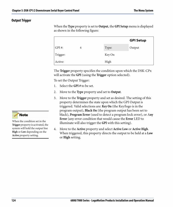
Chapter 5: DSK-CP1/2 Downstream Serial Keyer Control Panel The Menu System
Output Trigger
When the Type property is set to Output, the GPI Setup menu is displayed as shown in the following figure:
The Trigger property specifies the condition upon which the DSK-CPx will activate the GPI (using the Trigger option selected).
To set the Output Trigger:
1. Select the GPI # to be set.
2. Move to the Type property and set to Output.
3. Move to the Trigger property and set as desired. The setting of this property determines the state upon which the GPI Output is triggered. Valid selections are: Key On (the Key/logo is in the program output), Black On (the program output has been set to black), Program Error (used to detect a program lock error), or Any Error (any error condition that would cause the Error LED to illuminate will also trigger the GPI with this setting).
4. Move to the Active property and select Active Low or Active High. When triggered, this property directs the output to be held at a Low or High setting.
GPI Setup
GPI #: 4 Type: Output
Trigger: Key On
Active: High
When the condition set in the Trigger property is activated, the system will hold the output line High or Low depending on the Active property setting.
124 6800/7000 Series - LogoMotion Products Installation and Operation Manual

The Menu System Chapter 5: DSK-CP1/2 Downstream Serial Keyer Control Panel
Panel Setup1
The Panel Setup1 menu contains the Memory #, Save, and Recall properties. This menu allows you to save and restore various panel setups and also allows the recall of the default panel settings.
A Memory # is used to identify each saved Panel Setup. For example, the figure above shows the Memory # 6 representing a specific panel configuration. Valid Memory #s are 0 to 8; however, Memory # zero (0) is a special read-only memory selection used to store and recall the default Panel Setup.
Therefore, the operator can use only Memory #s 1 to 8.
To save a panel setup:
1. Display the Panel Setup1 menu.
2. Move to the Memory # property and set to the number desired.
3. Move to the Save property. Set the option to Yes.
4. The current Panel Setup and Soft Button menu setups are saved under the Memory # selected. The saved data contains: Type (Single/Group), System menu (On/Off), or Program/Preview (On/Off).
To recall a Panel Setup:
1. Display the Panel Setup1 menu.
2. Move to the Memory # and select the Panel Setup number you wish to recall (0 - 8).
3. Move to the Recall property and set to Yes.
4. The Panel Setup configuration and Soft button configurations that were last saved under the Memory # are recalled and loaded for operation.
Panel Setup1
Memory # Save Recall
6 No No
The Panel Setup menus and the Soft Button menus are associated, in that access to the Soft button menus is through the Panel Setup2 menu. The Soft Button menu settings are saved and recalled along with the Panel Setup menus under the same Memory #.
Selecting of the Memory # 0 recalls and loads the default settings.
6800/7000 Series - LogoMotion Products Installation and Operation Manual 125

Chapter 5: DSK-CP1/2 Downstream Serial Keyer Control Panel The Menu System
Panel Setup2
This menu contains the Cntrst (Contrast), Bklght (Backlight), Menu Out, and Control Pan ID (Panel ID) properties.
• The Cntrst selections are 0 to 15. A zero setting provides little contrast while a setting of 15 produces the most contrast.
• The Bklght selections are 0 to 7. Zero produces a dimmer screen while 7 produces a brighter one.
• The Menu Out setting is the time-out (amount of delay) given before the system reverts the screen display to the Keyer Status menu. The Menu Time-Out selections are:
• None
• 5 seconds
• 15 seconds
• 30 seconds
• 1 minute (default setting)
• The Pan ID (Control Panel) is actually the XY address with settings from 0X0 to 0XFFFF. Use the Control knobs to select the desired Pan ID.
Panel Setup2
Cntrst: 7 Bklght: 5
Menu Out: None
Pan ID: 0000
It is especially important that the Control Panel ID be different from that of every other panel or other device on the XY Bus. If it is not different, you may experience difficulties with the system.
126 6800/7000 Series - LogoMotion Products Installation and Operation Manual

The Menu System Chapter 5: DSK-CP1/2 Downstream Serial Keyer Control Panel
Soft Button
The Soft Button menu allows you to program the Soft buttons in the menu system rather than manually pressing and holding them down. It contains the SB # property (Soft Button # Property) with a selection range of 1 to 5 (one for each Soft button).
• The Type property selections are Menu or Keyer.
• The Menu field displays the name of each control panel menu in order, allowing the operator to scroll through them.
The Property field displays the name of the modifiable properties available on the selected menu (shown in the Menu field). Here you can scroll through the modifiable properties (for the selected menu) displaying one after the other. If the Property field is left blank, the programmed Soft button only jumps to the selected menu (not a property).
For example, in the figure shown above, the Menu field displays Status (Keyer Status menu) and the Property field displays KeyInv (Key Invert).
If the Property field Control knob is turned, the next available modifiable property is displayed in sequence. For instance, as the selections are scrolled through, FTB would be displayed next, followed by Auto.
To set the Type property:
1. Select the SB # that you wish to program.
2. Move to the Type property and set to Menu or Keyer. The Type set determines if the Soft button is programmed to a menu and/or to one of its properties or to a Keyer (or Group) and its settings.
Soft Button
SB #: 2 Type: Menu
Menu Property
Status KeyInv
When the Type property is set to Menu the Soft Button menu is displayed as shown in the figure above.
6800/7000 Series - LogoMotion Products Installation and Operation Manual 127

Chapter 5: DSK-CP1/2 Downstream Serial Keyer Control Panel The Menu System
To display a menu:
1. Display the Soft Button menu.
2. Use the cursor buttons to highlight the SB # Property (Soft Button #). The corresponding property containing the number is underlined.
3. Turn the Control knob to select the SB # button you wish to program. Selections are 1 to 5, one number for each of the Soft buttons.
4. Move to the Type property.
5. Turn the Control knob to set the Type property to Menu
6. Move to the Menu property and use the Control knobs to select the name of the menu you want this Soft button to be programmed to display. The Soft button selected is now programmed to display the selected menu.
To display a property:
1. Follow Steps 1 through 6 as listed above.
2. Move to the Property field.
3. Turn the Control knob to select the property desired.
The Soft button is now programmed to the property selected.
When the Type property is set to Keyer, the second Soft Button menu is displayed as shown above. This menu allows the operator to program a Soft button to a specified Keyer (by name) and as a program or preview Keyer if desired.
• The SB # and Type properties are the same as on the first Soft Button menu.
• The Key1/Prg (Keyer one/program) property contains the name of the Keyer assigned to Program.
• The Key2/Prv (Keyer two/preview) property contains the name of the Keyer assigned to Preview.
Soft Button
SB #: 2 Type: Keyer
KEY1/PRG Key2/Prv
Name 1 Name 2
Soft button actions/functions take effect at the release of the button.
128 6800/7000 Series - LogoMotion Products Installation and Operation Manual

The Menu System Chapter 5: DSK-CP1/2 Downstream Serial Keyer Control Panel
To select a Keyer or Group to be programmed to a Soft button, the Keyer Modules must already be controlled by the control panel. If they are not, simply add the name of the Keyer or Keyer Group to the DSK-CPx Name List. For more information, see “Name Add” on page 121.
1. Display the Soft Button menu and select the SB # you wish to program.
2. Set the Type property to Keyer.
3. Move to the Key1/Prg property. Select the name of the Keyer or Keyer Group by turning the associated Control knob.
4. To select a second Keyer or Keyer Group, move to the Key2/Prv property value, and select the name of the second Keyer or Group to be programmed to this Soft button.
Be aware of these Soft button Actions:
1. If a Soft button is programmed to a specific menu, that menu is displayed when that Soft button is pressed.
2. If a Soft button is programmed to a specific property on a menu, pressing the Soft button results in the display of the menu containing the specified property. The property value changes when the Soft button is released.
On a menu with three or fewer modifiable properties, Soft buttons cannot be programmed to a specific property by holding the Key down since they are already automatically linked to one of three knobs. On this kind of menu (with three or fewer properties), the Soft button menu can be used to program a Soft button to jump to a specific property. With four or more modifiable properties, the user can scroll through them with the cursor buttons, highlight a specific one, and program it to a given Soft button by holding the Key down.
3. If the property specified is a toggle-type Action property, then pressing the assigned Soft button results in that action being toggled On or Off. If the Action toggled was On, the state is toggled to Off and vise versa; however, the associated menu is not displayed.
4. When more than one Soft button has been programmed to select Program Preview Keyer Pairs and the control panel has Prg/Prv set to On, pressing a Soft button results in the Prg/Prv Keyers being selected for the next transition.
See “Soft Button” on page 127 for important Soft button attributes.
6800/7000 Series - LogoMotion Products Installation and Operation Manual 129

Chapter 5: DSK-CP1/2 Downstream Serial Keyer Control Panel Modes of Operation
Modes of OperationThe DSK-CPx can address the Keyers in three modes that can be overlapped and combined as described later in this section. The modes of operation are:
• Individual (Keyer)
• Group Control
• Program/Preview
In each mode, the control panel configures all settings and initiates all transitions on one or more Keyers. The GPI controls are mirrored to the DSK-CPx.
The Keyer settings on a DSK-CPx can be changed via the GPI, DSK-CPx, or DSK-6801/3 front edge controls. There is no mechanism for locking out controls. If one Keyer is being controlled from the front edge controls and another from the GPI, there will be conflicts. In normal operation, Keyer settings should be modified from one control point only.
Individual ModeThe Individual mode allows the operator to set the parameters of a single Keyer. All settings displayed on the control panel reflect the configuration of the Keyer specified (by name) and selected by the operator. Transitions initiated by the operator via the control panel occur on that specific Keyer only.
Group ModeThe Group mode allows the operator to transition all of the Keyers within a single group. Each group has a Master Module designated by the Keyer ID of 0 (zero). All settings displayed reflect the configuration of the master of the group.
Changing settings on the Master Module using front edge controls, generates a message to the control panel, which then updates all the modules in the group.
If the GlbCmd property is set to On, all Keyer settings can be changed on all Keyers within the group.
Transitions initiated via the control panel occur on all Keyers within the group simultaneously.
130 6800/7000 Series - LogoMotion Products Installation and Operation Manual

Modes of Operation Chapter 5: DSK-CP1/2 Downstream Serial Keyer Control Panel
Transitioning Multiple Keyers with Different SettingsWhen the transition of many Keyer Modules is desired at the same time and each Keyer Module has different Keyer settings, use the following to set transition control:
1. Set the DSK-CPx to Individual mode control.
2. Select a Keyer Module and modify the settings as desired.
3. Repeat Step 2 for each Keyer Module desired in the transition.
4. Change to Group mode control and select the type of transition (Cut, Auto Trans, FTB, or a Manual Fade) desired for the Keyer Modules. All selected Keyers are transitioned together.
Program/Preview ModeThe Program/Preview mode allows you to set the operating parameters on the Keyers in pairs, such that one Keyer represents the program output and the other a preview of the program after the next transition occurs.
In this mode, all Keyer settings are mirrored to both Keyers, and all transitions occur opposite to each other. For example, if the Program Key is faded Off, the Preview Key will fade On. The only exception to this mirror effect occurs when the program is faded to or from black. Since a black preview would not be helpful, the preview never fades to black.
A maximum of five Program/Preview pairs can be controlled by the DSK-CPx.
6800/7000 Series - LogoMotion Products Installation and Operation Manual 131

Chapter 5: DSK-CP1/2 Downstream Serial Keyer Control Panel Setting the Device Address
Setting the Device AddressEach DSK-6801/3 connected to a DSK-CPx must have a unique Device Address. The Device Address is achieved by setting the Group ID and Keyer ID on each Keyer Module. The following procedures show how to add a name to the Name List, and set up the Device Address, Group, Panel and Keyer IDs.
Setting a Group IDThe Group ID is set using the Hex SW4 Switch located on top of the Keyer Module. For detailed information, see Figure 5-15 “Group ID Hex SW4”.
Figure 5-15. Group ID Hex SW4
1. To set a Group ID, turn the Hex switch (see Figure 5-15 “Group ID Hex SW4”) to one of the 16 positions available (0 to F). The number/letter selected is now the Group ID. For example, if the Module Hex switch is set to position 6, that module has a Group ID of 6 and is controlled with Group 6.
GroupID
SW4HEX
HEX SW1
TOG SW2
TOG SW3
132 6800/7000 Series - LogoMotion Products Installation and Operation Manual

Setting the Device Address Chapter 5: DSK-CP1/2 Downstream Serial Keyer Control Panel
2. To change a Group ID, simply change the Keyer Module Hex switch to the desired position. For example, if the Hex switch is currently set to 6 and the operator now wants this module to be in Group A, changing the switch from position 6 to A gives this module a Group ID of A.
Within each Group there is a Master Module. The Master Module is the only Keyer that has two-way XY Bus communication with the DSK-CPx. Within a group, the Keyer with the Keyer ID of 0 (zero) is designated as the Master Module.
Changing the Master Module settings at the keyer level (via front edge controls) creates a message which is sent to the control panel, allowing it to update all Keyer settings within that Group.
If a Slave Keyer (non-master) has its settings changed (via front edge controls), the control panel is not notified or updated.
Setting a Keyer IDThe Keyer ID on a DSK-6801/3 module consists of selecting an address value in both the upper and lower part of each address setting.
The DSK-6801/3 Keyer ID is set as follows:
1. Turn the front Hex SW1 to Position 0, toggle SW2 Up or Down until the Shift State 2 LEDs are illuminated. The system is now in Shift State 2.
2. Turn Hex SW1 to position B.
3. Toggle SW2 to select the desired upper portion of the address.
4. Pressing up on SW2 adds 16 to the address value.
5. Pressing down on SW2 subtracts 16.
6. Move Hex SW1 to position C.
7. Toggle SW2 to select the lower portion of the address.
8. Press up on SW2 to add 1 (one) to the address value.
9. Press SW2 down to subtract one. The address is displayed on the LEDs in Binary.
When selecting the address, see Figure 5-16 on page 134 for reference.
6800/7000 Series - LogoMotion Products Installation and Operation Manual 133

Chapter 5: DSK-CP1/2 Downstream Serial Keyer Control Panel Setting the Device Address
Setting a Device AddressSetting a Device Address consists of setting a Group ID and Keyer ID. See Figure 5-16 on page 134.
Figure 5-16. Setting a Device Address
1. Set Hex SW4 to the Group position desired (0-F).
2. Set the Keyer ID address using Shift State 2 and Hex SW1 in position B (for upper four address bits) and toggle SW2 until desired number is achieved. See “Setting the Panel ID” on page 135 for numbering information.
3. Move Hex SW1 to position C for the lower four address bits. Toggle SW2 until the desired number is achieved.
4. Give the Keyer a name using the Name Add menu. See “Name Add” on page 121 for detailed information.
5. Assign the Keyer to a Soft button if it will be used in Multiple mode or in Program/Preview mode.
6. Designate the Keyer as Key1/Pgm (program) or as Key2/Prv (preview) side. See “Program/Preview Mode” on page 131 for more information.
7. List the new Device Address on the Name List maintained by the DSK-CPx. See “Name Add” on page 121 for more information.
8. Label the Keyer with the appropriate information to simplify troubleshooting and system additions. For example, affix a label on the Keyer with the name or group assigned it.
Keyer ID
Position B Position CDevice Address = Group ID + + (Upper Address
Value)(Lower Address
Value)
134 6800/7000 Series - LogoMotion Products Installation and Operation Manual

Setting the Device Address Chapter 5: DSK-CP1/2 Downstream Serial Keyer Control Panel
Setting the Panel IDThe Pan ID (Panel ID) identifies a specific control panel. Each Pan ID must be unique from all other Pan IDs. The Pan ID settings range from 0 x 0 to 0 x FFFF and can be selected using the Control knobs. Each DSKCPx must have a unique Pan ID or else the operator may experience difficulties with the system, particularly in Multiple mode.
MSB LSB MSB LSB
MOD1 MOD2 MOD3 MOD4Upper Address Value
MOD1 MOD2 MOD3 MOD4Lower Address Value
Off Off Off Off 0 Off Off Off Off 0
Off Off Off On 16 Off Off Off On 1
Off Off On Off 32 Off Off On Off 2
Off Off On On 48 Off Off On On 3
Off On Off Off 64 Off On Off Off 4
Off On Off On 80 Off On Off On 5
Off On On Off 96 Off On On Off 6
Off On On On 112 Off On On On 7
On Off Off Off 128 On Off Off Off 8
On Off Off On 144 On Off Off On 9
On Off On Off 160 On Off On Off 10
On Off On On 176 On Off On On 11
On On Off Off 192 On On Off Off 12
On On Off On 208 On On Off On 13
On On On Off 224 On On On Off 14
On On On On 240 On On On On 15
6800/7000 Series - LogoMotion Products Installation and Operation Manual 135

Chapter 5: DSK-CP1/2 Downstream Serial Keyer Control Panel Installation
InstallationThere is a great deal of information to consider when setting up a system. It is suggested you read this chapter for reference and check the XY connection diagrams and operational modes for information that will help determine how to set up the system as desired.
Rear Module XY ConnectionsFor the control panel to control the Keyers, both the control panel and Keyers must be connected to the XY Bus. This is achieved by connecting a cable from the XY BNC on the rear of the DSK-CPx to the XY connectors on the frame containing the Keyer Module. Once this connection is made, the control panel is capable of controlling that Keyer.
To connect the XY Bus to the rest of the Keyers, simply connect a cable from the XY Loop connector on the frame to the XY connector on the next Keyer’s frame connections, as illustrated in the following diagram.
The order in which the Keyers are attached to the XY Bus is generally unimportant; however, if any Keyer is more critical than another, it is recommended that it be connected as early as possible on the bus. This is only a concern when the XY cable is disrupted, and Keyers beyond the disruption are unreachable.
Other fail-safe mechanisms (such as GPIs) can be set up to coexist with the DSK XY network.
For EMI compliance, the DSK-CPx must be terminated at both ends.
136 6800/7000 Series - LogoMotion Products Installation and Operation Manual
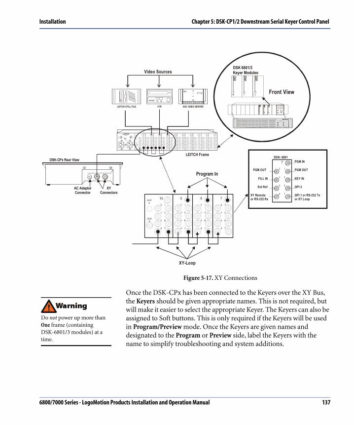
Installation Chapter 5: DSK-CP1/2 Downstream Serial Keyer Control Panel
Figure 5-17. XY Connections
Once the DSK-CPx has been connected to the Keyers over the XY Bus, the Keyers should be given appropriate names. This is not required, but will make it easier to select the appropriate Keyer. The Keyers can also be assigned to Soft buttons. This is only required if the Keyers will be used in Program/Preview mode. Once the Keyers are given names and designated to the Program or Preview side, label the Keyers with the name to simplify troubleshooting and system additions.
LEITCH STILL FILE VTR ASC VIDEO SERVER
ASC
Video Sources
DSK-CPx Rear View
AC AdaptorConnector
XYConnectors
PO W ER ON
OV ER HEAT OF F
P . S.OV E RHE AT
P . S.OV E RHE AT
Digit al Glu e
FR -6 8 0 4P O WE R P O WE R
DSK 6801/3Keyer Modules
Front ViewDSK-68
01
DSK-6801
DSK-6801
LEITCH Frame
Program In
XY-Loop
PGM IN
PGM OUT
KEY IN
GPI 2
GPI 1 or RS-232 Tx or XY Loop
PGM OUT
FILL IN
Ext Ref
XY Remoteor RS-232 Rx
DSK- 6801
2 1
4 3
6 5
8 7
7
Do not power up more than One frame (containing DSK-6801/3 modules) at a time.
6800/7000 Series - LogoMotion Products Installation and Operation Manual 137

Chapter 5: DSK-CP1/2 Downstream Serial Keyer Control Panel Installation
DSK Keyer Module Setup RequirementsDSK keyer Module set up requirements are listed below:
• Jumper settings
• Hex switch settings for Group/Keyer ID.
138 6800/7000 Series - LogoMotion Products Installation and Operation Manual

System Applications Chapter 5: DSK-CP1/2 Downstream Serial Keyer Control Panel
System ApplicationsConfiguration examples are provided in this section to help set up different types of systems. However, configurations are not limited to the examples shown. The operator is free to interconnect and control the DSK-CPx system as desired. There are several types of video sources shown, and many other types are available and can be used. Also shown are different ways of terminating the XY Bus. In the following figures are several DSK-CPx system configurations and suggestions for setting up Group IDs, Keyer IDs, and Keyer names. A few things to note in all of the examples given are:
• The names are set to values that help to identify a DSK-6801/3 module and what it keys, or the program input on a DSK-6801/3 module and what it keys.
• Each Keyer or group of buttons is given a name which can be used to select a specific Keyer/Group to be controlled.
6800/7000 Series - LogoMotion Products Installation and Operation Manual 139

Chapter 5: DSK-CP1/2 Downstream Serial Keyer Control Panel System Applications
Connecting a Single Keyer SystemIn this example, one DSK-CPx controls one Keyer Module.
• A DSK-6801/3 has a default Keyer ID value of zero, so the Keyer ID value does not need to be changed.
• The Group ID is set to the value indicated on the Group ID Hex switch.
• The Panel ID defaults to zero, so it should be changed to one (expressed as 0 x 0001) (see Figure 5-18 “Single Keyer System”).
Figure 5-18. Single Keyer System
DSK-6801/3
GRP ID = 0KEY ID = 0Name: PGM00
KEY
FILL PGMOUT
75 OhmTermination
Output of Production Master Control Switcher
PGMFEED
XY-
BU
S
Logomotion, PROM Slide, ASC Video Server, etc.
Static or Animated Logo,Titles, Chroma Key
Panel IDset to one
75Ω
75Ω
140 6800/7000 Series - LogoMotion Products Installation and Operation Manual

System Applications Chapter 5: DSK-CP1/2 Downstream Serial Keyer Control Panel
Connecting a Multi-Level Keying SystemIn this example of multi-level Keying, the Program Output of one Keyer Module is connected to the Program Input of another Keyer Module. The XY loop-through connections on the rear of the Keyer Module frame are used to connect the frame to the XY Bus.
The suggested name for each Keyer Module is related to its video source. This way you control the CG Keyer, simply dial-up the CG Keyer name on the DSK-CPx, and then make the changes to that Keyer Module.
Alternatively, the operator can assign each Keyer Module to a programmable Soft button. When a Soft button is pressed, the LED is illuminated and changes can be made to the selected Keyers. The changes can be “Key” transitions or modification of the Keyer settings. Set the GlbCmd Property to Off when multiple soft buttons have been programmed to select Keyers.
Figure 5-19. Multi-Level Keying System
VTR
75 OhmTermination
75Ω 75Ω
6800/7000 Series - LogoMotion Products Installation and Operation Manual 141

Chapter 5: DSK-CP1/2 Downstream Serial Keyer Control Panel System Applications
Connecting a Program/Preview SystemA Program/Preview system is the most complicated system to set up. The following figure shows Keyer Modules on the program path named with the suffix PGM and the Preview Keyers named with the suffix PRV. The prefix of the Keyer name relates to its order in the Program/Preview path. The first Keyer Module in the Program path has the prefix K1 and the last Keyer in the Program path has the prefix K5. The Keyers in Program and Preview paths are cascaded one after the other.
The Key sources are identical for each pair in the Program/Preview paths. The Keyers in the Preview path show what the Program Output will look like after a transition.
Each Program/Preview pair should be assigned to a Soft button; otherwise, control of Keyers in the Program/Preview mode becomes difficult.
142 6800/7000 Series - LogoMotion Products Installation and Operation Manual

System Applications Chapter 5: DSK-CP1/2 Downstream Serial Keyer Control Panel
Procedure for Setup of a Program/Preview SystemThe Program and Preview Keyers are organized in pairs:
Make sure the Keyers are on the Name List; if not, add them.
1. Program each Soft button with the name of the Prg/Prv (Program and Preview) Keyer pairs.
2. Set the DSK-CPx into Prg/Prv mode in the System Setup menu. Set the Prg/Prv field to Yes to enable the Prg/Prv mode.
3. To select multiple Prg/Prv pairs for transitioning, program more than one Soft button with a Program/Preview Keyer pair and set the GlbCmd property to Off.
For a demonstration, see Figure 5-20 “Program/Preview System”on page 144.
6800/7000 Series - LogoMotion Products Installation and Operation Manual 143

Chapter 5: DSK-CP1/2 Downstream Serial Keyer Control Panel System Applications
Program Preview System
Figure 5-20. Program/Preview System
144 6800/7000 Series - LogoMotion Products Installation and Operation Manual

System Applications Chapter 5: DSK-CP1/2 Downstream Serial Keyer Control Panel
Connecting a Group SystemIn this example, the Keyer Modules that key the weather warning are named with the suffix WTR. The Keyer Modules that key the network logo are named with the suffix LGO. The prefix of each Keyer name corresponds to the video source on the Program Input.
Each set of Keyers (weather warning or logo) have been set to operate within the same Group, meaning they have the same Group ID. Therefore, the group of Keyers that key the weather or the Group that keys the logo can be transitioned at the same time (as one Group).
Programming a Soft button to select a group allows the transition of all Keyers in that group at the same time. Program Soft buttons to the other groups and the operator can select more than one Group at a time (press more than one Soft button) and transition all of the selected Groups at the same time.
For a demonstration, see Figure 5-21 “Group System Configuration”on page 146.
6800/7000 Series - LogoMotion Products Installation and Operation Manual 145

Chapter 5: DSK-CP1/2 Downstream Serial Keyer Control Panel System Applications
Group System Configuration
Figure 5-21. Group System Configuration
146 6800/7000 Series - LogoMotion Products Installation and Operation Manual

System Applications Chapter 5: DSK-CP1/2 Downstream Serial Keyer Control Panel
6800/7000 Series - LogoMotion Products Installation and Operation Manual 147

Chapter 5: DSK-CP1/2 Downstream Serial Keyer Control Panel System Applications
148 6800/7000 Series - LogoMotion Products Installation and Operation Manual

Appendix A
Quick Reference Guide
OverviewThis Quick Reference Guide contains sections which enable the operator to quickly install a DSK-CPx and address a Keyer Module. This Appendix also contains a section on Error Messages, Troubleshooting, and the Diagnostic Mode.
6800/7000 Series - LogoMotion Products Installation and Operation Manual 149

Appendix A: Quick Reference Guide Setting Control for One or More Keyers
Setting Control for One or More Keyers1. Identify how the Keyer Module will be used. For example, if Keyers
will be transitioned together (the majority of the time), then set the Group ID of each Keyer to the same value (they are all in the same Group).
2. If there are less than 16 Keyers or if you wish to transition any combination of Keyers independently, then, give each Keyer a unique Group ID. See “Setting a Group ID” on page 132.
3. Give each Keyer Module a Keyer ID. See “Setting a Keyer ID” on page 133.
4. Set the mode of operation on the control panel via the System Setup menu.
5. Set the jumpers on the DSK-6801/3 to accept the XY Bus input.
6. Assign a Panel ID to the DSK-CPx. See “Setting the Panel ID” on page 135.
7. To add the Keyer Modules to the control panel Name List, see “Name Add” on page 121.
8. Select the Keyer or Group to be controlled. Change the Keyer settings and/or transition the Key on the Keyer Modules. See “Menu Controls” on page 108, and see “Dedicated Transition Buttons” on page 96.
9. Do not power up more than one frame of DSK-6801/3 modules at a time.
150 6800/7000 Series - LogoMotion Products Installation and Operation Manual

Setting Control for One or More Keyers Appendix A: Quick Reference Guide
DSK Control LayoutThe DSK-CPx provides the capability to control and change operational settings on the DSK-6801/3 Keyer Modules. The control panel features five dedicated buttons for commonly used operator functions and five Soft programmable buttons for panel customization.
The DSK-CPx has three major functional areas: the Transition controls area, the Settings area, and the Fade to Black button, each of which is described in the following section.
Figure A-1. DSK-CPx Layout
SettingsTransitionControls
Fade To Black Button
Dedicated Buttons
Programmable SoftButtons
Control Knobs
LCDScreen
CursorButtons
6800/7000 Series - LogoMotion Products Installation and Operation Manual 151

Appendix A: Quick Reference Guide Setting Control for One or More Keyers
Transition Controls
The Transition controls determine how a logo will be used by the Program Output. The logo will be one of the following:
• Cut
• Faded
• Wiped on
• Wiped off the program output
Settings
The Settings area consist of the following:
• Dedicated Setup buttons which can select Control menus, change menu properties, or select Keyers.
• Programmable Soft buttons can be programmed to select specific menus, change menu property settings, and to select Keyers/Groups.
• An LCD screen which displays menus with property settings available for modification.
Certain menus control the Keyer settings, some change the control panel settings, and some modify system-related settings. Any menu that allows modifications to Keyer settings displays the Name of the currently controlled Keyer (or Group) on the LCD screen which allows the user to distinguish between Keyers or Groups when controlling more than one.
Once a menu is selected and displayed, Up and Down white cursor buttons are used to scroll between menu selections. The Left and Right cursor buttons are used to highlight the adjustable properties on the menu displayed, and the Control knobs change the displayed values. See “Menu Controls” on page 108 for detailed information.
Fade to Black Button
The Fade to Black button fades a Keyer Module program output to black. The fade rate can be changed on the Rates Setup menu (accessed by the Trans Setup dedicated button).
152 6800/7000 Series - LogoMotion Products Installation and Operation Manual

Setting Control for One or More Keyers Appendix A: Quick Reference Guide
MenusThe DSK-CPx contains 16 menus. The menus are divided into five categories which are represented by the five control menus:
1. Keyer Setup contains properties for Keyer setup.
2. Trans Setup contains settings for Transition Rates, Mask, Wipe, and Chroma Key.
3. Panel Setup contains panel settings, Soft programmable button setup, and Keyer status information.
4. System Setup contains mode settings, Name Add and Remove settings, and GPI settings.
5. Keyer/Grp ID contains Keyer and Group ID information.
The DSK-CPx menus are linked in a simple list format. This linked format has a set flow as illustrated in Figure 5-2. The dedicated Setup buttons are pre-programmed to display a specific menu when pressed. Each of these menus is a control menu (one of the five listed above), and each controls its own group of linked menus. The menus linked to a control menu are selected by using the Up and Down white cursor buttons to scroll through the linked menus.
6800/7000 Series - LogoMotion Products Installation and Operation Manual 153

Appendix A: Quick Reference Guide Setting Control for One or More Keyers
Figure A-2. DSK-CPx Menu Map
Off
Mix
Off
Off
154 6800/7000 Series - LogoMotion Products Installation and Operation Manual

Setting Control for One or More Keyers Appendix A: Quick Reference Guide
Selecting and Changing a MenuTo make changes to the modifiable property fields contained on the various menus, perform the following:
Use the Control knobs to select (display) the menu desired.
1. A menu can be selected by pushing a dedicated setup button, by scrolling with the Up and Down cursor buttons, or by pushing a programmed Soft button.
2. Once the selected menu is displayed, use the Left and Right cursor buttons to move between menu properties. The property Label field is highlighted, and the modifiable property field is underlined.
3. Turn any Control knob to change to display to the desired value. See “Using the Control Knobs” on page 109 for more information. On menus with three or fewer properties, each property is controlled by the Control knob directly below the property.
Summary of Control ModesThere are four modes of control which can be overlapped and combined as desired:
• Individual Keyer control
• Group control
• Program/Preview control
These modes of operation are dependent on how the video signals are connected to the Keyer Module. The control panel configures all settings and initiates all transitions of the Keyers in each mode. See “Modes of Operation” on page 130 for more information.
6800/7000 Series - LogoMotion Products Installation and Operation Manual 155
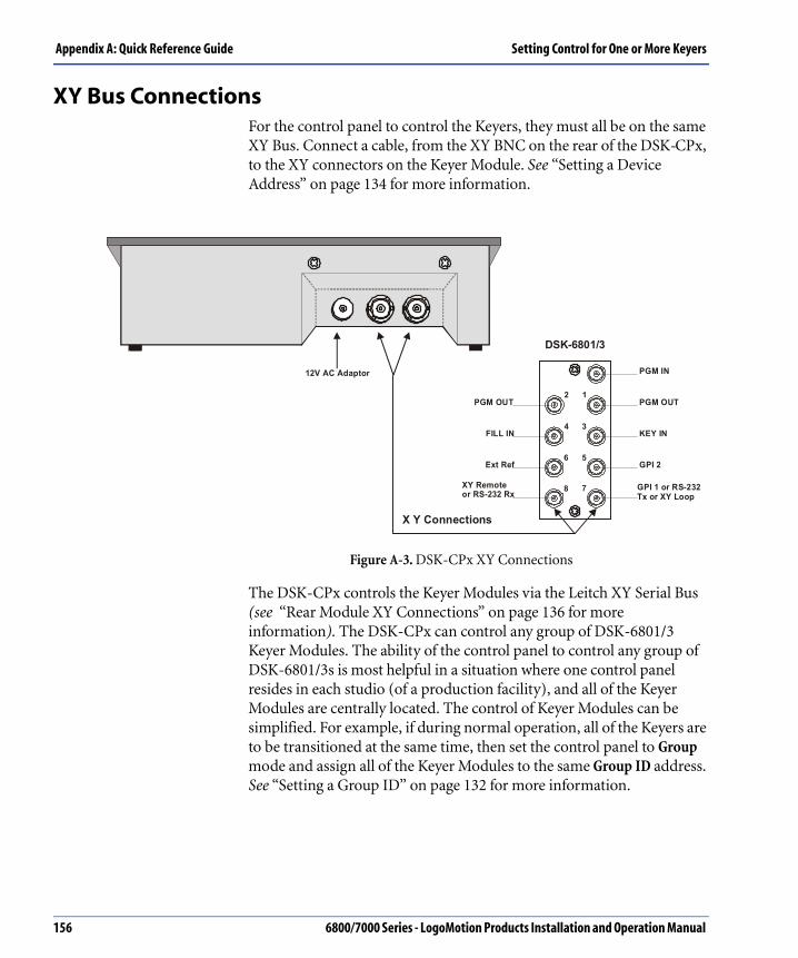
Appendix A: Quick Reference Guide Setting Control for One or More Keyers
XY Bus ConnectionsFor the control panel to control the Keyers, they must all be on the same XY Bus. Connect a cable, from the XY BNC on the rear of the DSK-CPx, to the XY connectors on the Keyer Module. See “Setting a Device Address” on page 134 for more information.
Figure A-3. DSK-CPx XY Connections
The DSK-CPx controls the Keyer Modules via the Leitch XY Serial Bus (see “Rear Module XY Connections” on page 136 for more information). The DSK-CPx can control any group of DSK-6801/3 Keyer Modules. The ability of the control panel to control any group of DSK-6801/3s is most helpful in a situation where one control panel resides in each studio (of a production facility), and all of the Keyer Modules are centrally located. The control of Keyer Modules can be simplified. For example, if during normal operation, all of the Keyers are to be transitioned at the same time, then set the control panel to Group mode and assign all of the Keyer Modules to the same Group ID address. See “Setting a Group ID” on page 132 for more information.
X Y Connections
PGM IN
PGM OUT
KEY IN
GPI 2
GPI 1 or RS-232Tx or XY Loop
PGM OUT
FILL IN
Ext Ref
XY Remoteor RS-232 Rx
DSK-6801/3
2 1
4 3
6 5
8 7
12V AC Adaptor
156 6800/7000 Series - LogoMotion Products Installation and Operation Manual

Setting Control for One or More Keyers Appendix A: Quick Reference Guide
Setting a Device AddressEach Keyer must have a unique Device Address by which the control panel recognizes and controls the modules. Combining the Keyer ID and the Group ID results in a unique Device Address. See FigureA-4. DSK-CPx Device Address.
Figure A-4. DSK-CPx Device Address
To assign a Keyer Module a Keyer ID and Group ID use the Hex and Toggle switches on the DSK-6801/3 modules. See “Setting the Device Address” on page 132 for more information.
Keyer ID
Position B Position CDevice Address = Group ID + + (Upper Address
Value)(Lower Address
Value)
6800/7000 Series - LogoMotion Products Installation and Operation Manual 157

Appendix A: Quick Reference Guide Error Messages
Error MessagesThere are several error messages that are displayed on the screen under certain conditions, as shown in the table below:
Error Message Possible Reasons Solutions
No response from DSK
This message indicates that there was no response from the selected Keyer Module.Possibilities are that the selected ID was not valid or that the specific Keyer is not responding for whatever reason, i.e.: not connected.
Check that the ID selected is valid and make sure the Name is on the Name List.Check the connections to the Keyer Module and control panel.
Name already used! This message indicates that the Name selected is already used for another Keyer.
Either choose another name, or first delete the Name and it can then be re-assigned.
Keyer has a Name The Keyer selected already has a Name.
This Name is already in the system, and it does not need to be added.
Cannot Delete Default
The Default Names cannot be deleted.
If your Name List is full and you want to delete Names to make room for new ones, delete Names you have added, not the Default Names.
Name List is Full The Name List is full (it holds 255 Names). Old Names must be deleted to make room for new Names.
Delete Names no longer used to make room for new Names.If all the Names are being used, try grouping Keyers or add another control panel.
158 6800/7000 Series - LogoMotion Products Installation and Operation Manual

Error Messages Appendix A: Quick Reference Guide
GlbCmd is OffTransition Cmd Only!
With the GlbCmd set to Off, only Transition control messages are sent to the selected Keyers.
To change settings (other than transitions) on selected Keyers, set GlbCmd to On.
Error Message Possible Reasons Solutions
6800/7000 Series - LogoMotion Products Installation and Operation Manual 159

Appendix A: Quick Reference Guide Troubleshooting
Troubleshooting This troubleshooting section is provided to assist you when common problems occur.
Common Problem Solution
When I press the Cut button, the screen displays a message that the Keyer is not responding. (Also valid for the Auto Trans and FTB buttons.)
a. Check that the Group and Keyer ID match those of the Keyer you are trying to control.
b. There may be a problem with your XY Bus if you cannot select any Keyers–check the connections to make sure the control panel is actually connected to the Keyers.
When I press a transition button, my Keyer doesn’t transition.
a. If your control panel is in Program/Preview mode, you must first select a Keyer; then it can be transitioned.
b. The Fader Handle must be on one of its end positions for the FTB, Auto Trans and Cut buttons to function.
160 6800/7000 Series - LogoMotion Products Installation and Operation Manual

Diagnostic Mode Appendix A: Quick Reference Guide
Diagnostic Mode
Control Panel Self-TestThe DSK control panel includes a self-test mode which tests each LED, button, and Control knob on the panel for proper functioning. To activate the Control Panel Self-Test, hold down the Keyer Setup button and the Cut button and push the Up cursor button.
To test the control panel buttons, press each button and note the feedback displayed on the bottom line of the LCD. If a button is functioning properly, the bottom line of the LCD will display the name of the button. If the name does not appear, an appropriate error message will be displayed, so the operator can correct the situation.
Rotating a Control knob will display the Control knob number and direction of turn. When the Fader Handle is moved from one end to the other, the LCD will display either Fade On or Fade Off. To exit or quit the Self-test mode, hold down the Keyer Setup button and the Cut button. and press the Up cursor button.
6800/7000 Series - LogoMotion Products Installation and Operation Manual 161

Appendix A: Quick Reference Guide Diagnostic Mode
162 6800/7000 Series - LogoMotion Products Installation and Operation Manual

Warranty
Leitch Incorporated ("Leitch") warrants to each original end-user purchaser or licensee (each, a "Customer") of hardware or software products manufactured by Leitch (each, a "Product"), or of non-warranty repair or other services provided by Leitch ("Services"), that each such Product and all such Services will be free from defects in materials and workmanship that adversely affect the Product's performance or the Services' intended purpose for a period (the "Warranty Period") of:
One year for server hardware Products;Two years for non-server, and Desktop hardware Products;Ninety days for parts, assemblies and supplies to support hardware Products previously sold to Customers;Ninety days for media of software licensed separately from Leitch hardware Products, and encoding created by Leitch as physically affixed on or embedded in such media; The same period as the hardware Product warranty for media of software licensed as an integral part of any Leitch hardware Product, and encoding created by Leitch as physically affixed on or embedded in such mediaNinety days for Services.
Please refer to the current "Leitch Limited Warranty Policy" for a complete description of the warranty provided, including important exclusions and limitations as well as procedures for obtaining warranty service.
B.fm Page 163 Thursday, January 16, 2003 3:50 PM