LOGIKA 3000 & 5000-V7B - tedwall.ietedwall.ie/mhrlogika30005000-fulltechnicalmanual-v7b-r1.pdf ·...
144
LOGIKA 3000 & LOGIKA 5000 SPECIFCATIONS LOGIKA 3000 & 5000-V7B-R1.doc 19/06/2007 MHR DESIGNS LTD. Logika House, Holborn Avenue, Mildenhall, Suffolk, IP28 7AN Tel: 01638 583900 Fax: 01638 583988 LOGIKA 3000 FLUSH GLAZED AND SILICON GLAZED DEMOUNTABLE PARTITION SYSTEM Incorporating LOGIKA 5000 “FRAMELESS” GLAZING SYSTEM SPECIFICATION & TECHNICAL MANUAL
Transcript of LOGIKA 3000 & 5000-V7B - tedwall.ietedwall.ie/mhrlogika30005000-fulltechnicalmanual-v7b-r1.pdf ·...
LOGIKA 3000 & LOGIKA 5000 SPECIFCATIONS LOGIKA 3000 & 5000-V7B-R1.doc 19/06/2007
MHR DESIGNS LTD. Logika House, Holborn Avenue, Mildenhall, Suffolk, IP28 7AN Tel: 01638 583900 Fax: 01638 583988
LOGIKA 3000 FLUSH GLAZED
AND SILICON GLAZED DEMOUNTABLE PARTITION SYSTEM
Incorporating LOGIKA 5000
“FRAMELESS” GLAZING SYSTEM
SPECIFICATION & TECHNICAL MANUAL
LOGIKA 3000 & LOGIKA 5000 SPECIFCATIONS LOGIKA 3000 & 5000-V7B.doc 26/09/2006
MHR DESIGNS LTD. Logika House, Holborn Avenue, Mildenhall, Suffolk, IP28 7AN Tel: 01638 583900 Fax: 01638 583988
SUMMARY FEATURES & BENEFITS
1. The LOGIKA 3000 PARTITION system is classified as a STUD and SHEET system under BS5234: part 1:1992 definition for partition structures. It is capable of satisfying the criteria for both Medium Duty or Heavy Duty determined by the choice of panel facing and internal structure selected from its range of components. LOGIKA 3000 glazing complies fully with BS6262 for “edge cover” and “back clearance” enhancing safety, and has been fire tested to BS476 part 22 for 74 minutes.
2. Versatility: The key to LOGIKA 3000 is VERSATILITY. The system employs a range of extruded aluminium profiles which in combination with a choice of internal framing offer a range of performance characteristics up to 3600mm high. All acoustic and fire performances are achieved within the common 77mm wall thickness, maintaining a common visual appearance in all specifications. This minimises the number of profiles required and keeps alteration costs low. Cheaper alternatives offer a degree of flexibility, but cannot offer an upgrade path for fire and acoustic privacy. From BS5234 the recommended acoustic performance for General Offices is 38d8(Rw) and for Private Offices the standard requires 44dB (Rw). LOGIKA 3000 can achieve up to 48dB (Rw) utilising standard components.
3. SIMPLICITY SHELVING HEAD: The latest head channel design provides support for the “screw-less “Simplicity” shelving system. A system of shelving that requires no special skills or fixings to install. This improves the reusability of the partition panels as no unsightly fixing holes are left when the shelving is relocated. The head also provides the additional flexibility of a recessed/compression head option.
4. ACOUSTIC PERFORMANCE: Within its 77mm width LOGIKA 3000 provides from 35dB (Rw) up to 48dB (Rw) sound performance. The acoustic upgrades can be performed at ANY time (i.e. during a reorganisation of a work area) and ALL MAIN VISIBLE FRAMEWORK REMAINS IN PLACE reducing disruption and cost.
SOLID 35dB, 42dB, 45dB and 48 dB (Rw) options
TIMBER DOOR SETS 30 - 36dB Rw (subject to base configuration)
GLAZING Up to 38dB Rw (single acoustic laminate) – Up to 42dB Rw (double glazed)
5. FIRE PERFORMANCE: The LOGIKA 3000 system provides up to 90 minutes fire rating in solid elevations, 74 minutes in glazed elevations and 50 minutes in door elevations when used in combination with LOGIKA 2000 solid panels.
SOLID UP TO 90 minutes using Logika 2000 solid construction
DOOR UP TO 50 minutes - STANDARD HEIGHT
GLAZING 60 minutes - GLASS AREA UP TO 3.6 Sq.m *
* incorporating Pyran Glass
6. VISUAL CHOICE
SOLID elevations:
"CONCEALED FIX' panel joints using pre-decorated bevel edged Gypsum panels.
Flush filled for a smooth permanent look.
Cover strip modular joints or Feature joint with cover strip and colour co-ordinated insert
7. Logika 3000 GLAZED elevations:
LOGIKA 3000 - FLUSH SINGLE OFFSET GLAZING in full or part height framed modules.
LOGIKA 3000 - FLUSH DOUBLE GLAZING in full or part height framed modules.
The above options can be supplied with INTEGRAL BLINDS.
8. LOGIKA 5000 – Glazing Systems
The LOGIKA 5000 range is fully compatible with LOGIKA 3000 and offers range of Slimline “frameless” single glazing components and a unique double glazed option utilising a transparent ghost post.
LOGIKA 5000S - Single Silicon jointed or patented “Dry Jointed” glazing with off-set or centralised 12mm safety glass.
LOGIKA 5000D - Double glazed “dry Jointed” clear ghost post – accepts 6.4mm and 6mm safety glass.
9. LOGIKA Architectural Ironmongery and Door Configurations
The Logika 3000 and Logika 5000 systems include a full range of high quality compatible stainless steel ironmongery and a full range of door configurations including:
High quality solid core veneered doors with concealed hardwood lippings
Glass doors in “frameless” and “framed” configurations.
6. AVAILABILITY AND SERVICE: -
The LOGIKA framing system is offered in ANY colour from the RAL or BS4800 range within 7-10 days of order receipt. Special door veneers may take up to 4 weeks to produce. In the event of URGENT needs SMALL QUANTITIES of coated material may be processed within 3 working days. If you have a large ongoing requirement we are prepared to consider stocking your specific colours in regularly used sections for Ex-Stock availability. All main profiles are held in stock coated in RAL 9010.
LOGIKA 3000 & LOGIKA 5000 SPECIFCATIONS LOGIKA 3000 & 5000-V7B.doc 26/09/2006
MHR DESIGNS LTD. Logika House, Holborn Avenue, Mildenhall, Suffolk, IP28 7AN Tel: 01638 583900 Fax: 01638 583988
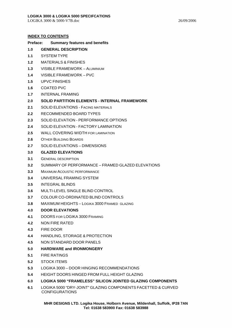
INDEX TO CONTENTS
Preface: Summary features and benefits
1.0 GENERAL DESCRIPTION
1.1 SYSTEM TYPE
1.2 MATERIALS & FINISHES
1.3 VISIBLE FRAMEWORK – ALUMINIUM
1.4 VISIBLE FRAMEWORK – PVC
1.5 UPVC FINISHES
1.6 COATED PVC
1.7 INTERNAL FRAMING
2.0 SOLID PARTITION ELEMENTS - INTERNAL FRAMEWORK
2.1 SOLID ELEVATIONS - FACING MATERIALS
2.2 RECOMMENDED BOARD TYPES
2.3 SOLID ELEVATION - PERFORMANCE OPTIONS
2.4 SOLID ELEVATION - FACTORY LAMINATION
2.5 WALL COVERING WIDTH FOR LAMINATION
2.6 OTHER BUILDING BOARDS
2.7 SOLID ELEVATIONS – DIMENSIONS
3.0 GLAZED ELEVATIONS
3.1 GENERAL DESCRIPTION
3.2 SUMMARY OF PERFORMANCE – FRAMED GLAZED ELEVATIONS
3.3 MAXIMUM ACOUSTIC PERFORMANCE
3.4 UNIVERSAL FRAMING SYSTEM
3.5 INTEGRAL BLINDS
3.6 MULTI-LEVEL SINGLE BLIND CONTROL
3.7 COLOUR CO-ORDINATED BLIND CONTROLS
3.8 MAXIMUM HEIGHTS – LOGIKA 3000 FRAMED GLAZING
4.0 DOOR ELEVATIONS
4.1 DOORS FOR LOGIKA 3000 FRAMING
4.2 NON FIRE RATED
4.3 FIRE DOOR
4.4 HANDLING, STORAGE & PROTECTION
4.5 NON STANDARD DOOR PANELS
5.0 HARDWARE and IRONMONGERY
5.1 FIRE RATINGS
5.2 STOCK ITEMS
5.3 LOGIKA 3000 – DOOR HINGING RECOMMENDATIONS
5.4 HEIGHT DOORS HINGED FROM FULL HEIGHT GLAZING
6.0 LOGIKA 5000 “FRAMELESS” SILICON JOINTED GLAZING COMPONENTS
6.1 LOGIKA 5000 “DRY-JOINT” GLAZING COMPONENTS FACETTED & CURVED CONFIGURATIONS
LOGIKA 3000 & LOGIKA 5000 SPECIFCATIONS LOGIKA 3000 & 5000-V7B.doc 26/09/2006
MHR DESIGNS LTD. Logika House, Holborn Avenue, Mildenhall, Suffolk, IP28 7AN Tel: 01638 583900 Fax: 01638 583988
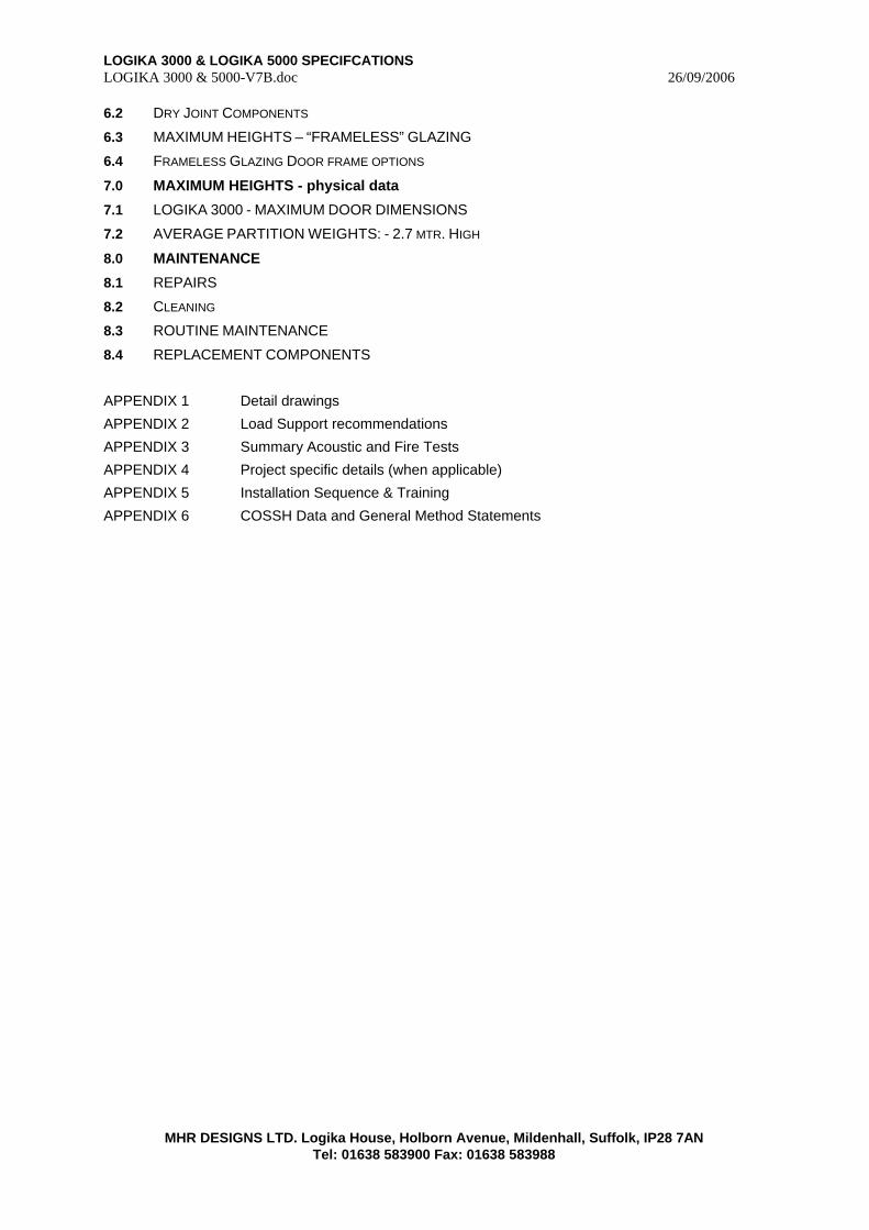
6.2 DRY JOINT COMPONENTS
6.3 MAXIMUM HEIGHTS – “FRAMELESS” GLAZING
6.4 FRAMELESS GLAZING DOOR FRAME OPTIONS
7.0 MAXIMUM HEIGHTS - physical data
7.1 LOGIKA 3000 - MAXIMUM DOOR DIMENSIONS
7.2 AVERAGE PARTITION WEIGHTS: - 2.7 MTR. HIGH
8.0 MAINTENANCE
8.1 REPAIRS
8.2 CLEANING
8.3 ROUTINE MAINTENANCE
8.4 REPLACEMENT COMPONENTS
APPENDIX 1 Detail drawings
APPENDIX 2 Load Support recommendations
APPENDIX 3 Summary Acoustic and Fire Tests
APPENDIX 4 Project specific details (when applicable)
APPENDIX 5 Installation Sequence & Training
APPENDIX 6 COSSH Data and General Method Statements
LOGIKA 3000 & LOGIKA 5000 SPECIFCATIONS LOGIKA 3000 & 5000-V7B.doc 26/09/2006
MHR DESIGNS LTD. Logika House, Holborn Avenue, Mildenhall, Suffolk, IP28 7AN Tel: 01638 583900 Fax: 01638 583988
1. GENERAL DESCRIPTION:
1.0 SYSTEM TYPE:
LOGIKA 3000 is an aluminium framed partition system which uses a range of primary profiles and clip-in secondary sections for a flexible and relocatable* system for dividing prestige commercial environments. The system is readily upgraded for acoustic and fire performance; matching that of many higher priced products, for executive privacy in highly sensitive areas. Using the principles of least cost design combined with the latest developments in materials, LOGIKA 3000 ensures an ECONOMICAL and FLEXIBLE solution for a wide range of situations. The extensive options provide the building owner with an advanced means of enhancing working environments for improved efficiency, safety and aesthetic appeal.
The system uses 6 primary components to form SOLID, GLAZING and DOOR elevations. Main junctions include:
90°corner with integral 3way adapter and “Y” post for direct extension to corners.
135° corner with integral 135° “Y” junction facility and a 165° corner for facetted designs.
The secondary sections offer a range of options to provide single offset or double FLUSH glazing, 35-48dB acoustic performance and range of fire ratings in solid, glazed and door elevations.
The system also allows backward compatibility with the LOGIKA 2000 glazing system to enable the system to be used alongside or as an extension to earlier installations.
LOGIKA 5000 is a fully compatible range of “frameless” glazing components where layouts demand a combination of solid, door and “frameless” glazing elevations.
* Full relocation (i.e. 100% reuse is only achievable where the existing characteristics of the proposed location match those of the original location i.e. floor to ceiling heights. The highest levels of reusability can be only achieved when recessed head and base options are incorporated.
1.1 MATERIALS & FINISHES
The main elements of LOGIKA 3000 and Logika 5000 are formed from non-combustible or self extinguishing materials.
1.2 VISIBLE FRAMEWORK - Aluminium:
A. MATERIAL:
Extruded from Aluminium grade 9TF to BS1474 under a BS5750 approved process.
B. ALUMINIUM STANDARD FINISH - POWDER COATINGS:
Powder coated, 60-90 microns conforming to BS6496, 6497 and AWA specifications. Applied by an approved applicator operating under a BS5750 certified process. The coating process is guaranteed for 15 years against deterioration of colour, gloss level and adhesion failure within normal office environments. Any cleaning materials should be checked for any adverse effect on colour and surface qualities prior to use. All colours in the BS4800 and RAL - F3 ranges are generally available, however as manufacturers regularly update the range offered. Please check the availability of the colour you require with our sales office.
C. STANDARD GLOSS LEVELS:
MATT/SATIN (semi gloss) min. gloss level 30% ± 5% @ 1 metre. @ 60°.
1.3 VISIBLE FRAMEWORK - PVC:
PVC GASKETS and INSERT TRIMS
A. MATERIALS:
LOGIKA 3000 glazing gaskets and trims are extruded to BS1763 from flame retardant PVC.
B. CO-EXTRUSIONS:
Forming Doors seals and glazing back seal also “optional” LOGIKA 2000 glazing sections used in conjunction with LOGIKA 3000 framing.
Rigid part - Medium impact VR400 UPVC
Soft part - Hardness No:66 @ 15 secs @ 23° type VG1402.
LOGIKA 3000 & LOGIKA 5000 SPECIFCATIONS LOGIKA 3000 & 5000-V7B.doc 26/09/2006
MHR DESIGNS LTD. Logika House, Holborn Avenue, Mildenhall, Suffolk, IP28 7AN Tel: 01638 583900 Fax: 01638 583988
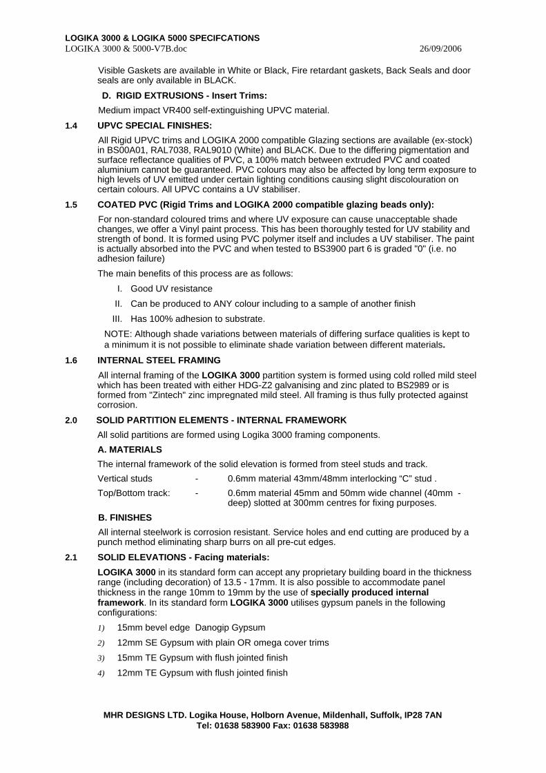
Visible Gaskets are available in White or Black, Fire retardant gaskets, Back Seals and door seals are only available in BLACK.
D. RIGID EXTRUSIONS - Insert Trims:
Medium impact VR400 self-extinguishing UPVC material.
1.4 UPVC SPECIAL FINISHES:
All Rigid UPVC trims and LOGIKA 2000 compatible Glazing sections are available (ex-stock) in BS00A01, RAL7038, RAL9010 (White) and BLACK. Due to the differing pigmentation and surface reflectance qualities of PVC, a 100% match between extruded PVC and coated aluminium cannot be guaranteed. PVC colours may also be affected by long term exposure to high levels of UV emitted under certain lighting conditions causing slight discolouration on certain colours. All UPVC contains a UV stabiliser.
1.5 COATED PVC (Rigid Trims and LOGIKA 2000 compatible glazing beads only):
For non-standard coloured trims and where UV exposure can cause unacceptable shade changes, we offer a Vinyl paint process. This has been thoroughly tested for UV stability and strength of bond. It is formed using PVC polymer itself and includes a UV stabiliser. The paint is actually absorbed into the PVC and when tested to BS3900 part 6 is graded "0" (i.e. no adhesion failure)
The main benefits of this process are as follows:
I. Good UV resistance
II. Can be produced to ANY colour including to a sample of another finish
III. Has 100% adhesion to substrate.
NOTE: Although shade variations between materials of differing surface qualities is kept to a minimum it is not possible to eliminate shade variation between different materials.
1.6 INTERNAL STEEL FRAMING
All internal framing of the LOGIKA 3000 partition system is formed using cold rolled mild steel which has been treated with either HDG-Z2 galvanising and zinc plated to BS2989 or is formed from "Zintech" zinc impregnated mild steel. All framing is thus fully protected against corrosion.
2.0 SOLID PARTITION ELEMENTS - INTERNAL FRAMEWORK
All solid partitions are formed using Logika 3000 framing components.
A. MATERIALS
The internal framework of the solid elevation is formed from steel studs and track.
Vertical studs - 0.6mm material 43mm/48mm interlocking “C” stud .
Top/Bottom track: - 0.6mm material 45mm and 50mm wide channel (40mm -deep) slotted at 300mm centres for fixing purposes.
B. FINISHES
All internal steelwork is corrosion resistant. Service holes and end cutting are produced by a punch method eliminating sharp burrs on all pre-cut edges.
2.1 SOLID ELEVATIONS - Facing materials:
LOGIKA 3000 in its standard form can accept any proprietary building board in the thickness range (including decoration) of 13.5 - 17mm. It is also possible to accommodate panel thickness in the range 10mm to 19mm by the use of specially produced internal framework. In its standard form LOGIKA 3000 utilises gypsum panels in the following configurations:
1) 15mm bevel edge Danogip Gypsum
2) 12mm SE Gypsum with plain OR omega cover trims
3) 15mm TE Gypsum with flush jointed finish
4) 12mm TE Gypsum with flush jointed finish
LOGIKA 3000 & LOGIKA 5000 SPECIFCATIONS LOGIKA 3000 & 5000-V7B.doc 26/09/2006
MHR DESIGNS LTD. Logika House, Holborn Avenue, Mildenhall, Suffolk, IP28 7AN Tel: 01638 583900 Fax: 01638 583988
Options 1 & 2 are available with factory laminated wall coverings. Options are 3 & 4 are site decorated using a wall covering or can be painted to match existing finishes.
2.2 RECOMMENDED BOARD TYPES:
When a fire performance in excess of 30 minutes is required and "relocatability" is not a high priority, option 3 or 4 should be chosen.
Where maximum sound performance, a fire performance up to 45 minutes and "relocatability" is essential, option should be chosen.
The flexible design of LOGIKA 3000 allows the incorporation of all of the above options within the SAME perimeter framework. It is also possible to finish opposite faces of the partition in different panel configurations of the same thickness. I.e. a partition wall can be built with 15mm flush jointed on one face with 15mm bevel edged on the opposite face.
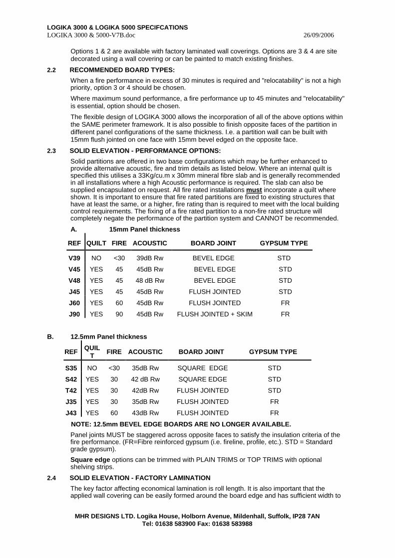
2.3 SOLID ELEVATION - PERFORMANCE OPTIONS:
Solid partitions are offered in two base configurations which may be further enhanced to provide alternative acoustic, fire and trim details as listed below. Where an internal quilt is specified this utilises a 33Kg/cu.m x 30mm mineral fibre slab and is generally recommended in all installations where a high Acoustic performance is required. The slab can also be supplied encapsulated on request. All fire rated installations must incorporate a quilt where shown. It is important to ensure that fire rated partitions are fixed to existing structures that have at least the same, or a higher, fire rating than is required to meet with the local building control requirements. The fixing of a fire rated partition to a non-fire rated structure will completely negate the performance of the partition system and CANNOT be recommended.
A. 15mm Panel thickness
REF QUILT FIRE ACOUSTIC BOARD JOINT GYPSUM TYPE
V39 NO <30 39dB Rw BEVEL EDGE STD
V45 YES 45 45dB Rw BEVEL EDGE STD
V48 YES 45 48 dB Rw BEVEL EDGE STD
J45 YES 45 45dB Rw FLUSH JOINTED STD
J60 YES 60 45dB Rw FLUSH JOINTED FR
J90 YES 90 45dB Rw FLUSH JOINTED + SKIM FR
B. 12.5mm Panel thickness
REF QUILT FIRE ACOUSTIC BOARD JOINT GYPSUM TYPE
S35 NO <30 35dB Rw SQUARE EDGE STD
S42 YES 30 42 dB Rw SQUARE EDGE STD
T42 YES 30 42dB Rw FLUSH JOINTED STD
J35 YES 30 35dB Rw FLUSH JOINTED FR
J43 YES 60 43dB Rw FLUSH JOINTED FR
NOTE: 12.5mm BEVEL EDGE BOARDS ARE NO LONGER AVAILABLE.
Panel joints MUST be staggered across opposite faces to satisfy the insulation criteria of the fire performance. (FR=Fibre reinforced gypsum (i.e. fireline, profile, etc.). STD = Standard grade gypsum).
Square edge options can be trimmed with PLAIN TRIMS or TOP TRIMS with optional shelving strips.
2.4 SOLID ELEVATION - FACTORY LAMINATION
The key factor affecting economical lamination is roll length. It is also important that the applied wall covering can be easily formed around the board edge and has sufficient width to
LOGIKA 3000 & LOGIKA 5000 SPECIFCATIONS LOGIKA 3000 & 5000-V7B.doc 26/09/2006
MHR DESIGNS LTD. Logika House, Holborn Avenue, Mildenhall, Suffolk, IP28 7AN Tel: 01638 583900 Fax: 01638 583988
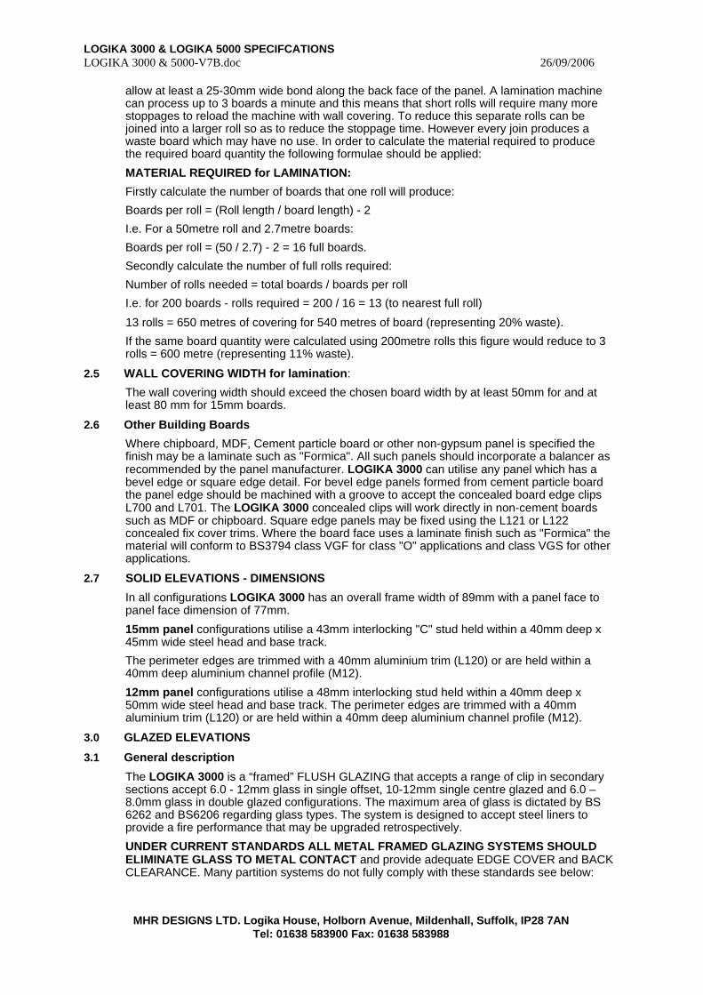
allow at least a 25-30mm wide bond along the back face of the panel. A lamination machine can process up to 3 boards a minute and this means that short rolls will require many more stoppages to reload the machine with wall covering. To reduce this separate rolls can be joined into a larger roll so as to reduce the stoppage time. However every join produces a waste board which may have no use. In order to calculate the material required to produce the required board quantity the following formulae should be applied:
MATERIAL REQUIRED for LAMINATION:
Firstly calculate the number of boards that one roll will produce:
Boards per roll = (Roll length / board length) - 2
I.e. For a 50metre roll and 2.7metre boards:
Boards per roll = (50 / 2.7) - 2 = 16 full boards.
Secondly calculate the number of full rolls required:
Number of rolls needed = total boards / boards per roll
I.e. for 200 boards - rolls required = 200 / 16 = 13 (to nearest full roll)
13 rolls = 650 metres of covering for 540 metres of board (representing 20% waste).
If the same board quantity were calculated using 200metre rolls this figure would reduce to 3 rolls = 600 metre (representing 11% waste).
2.5 WALL COVERING WIDTH for lamination:
The wall covering width should exceed the chosen board width by at least 50mm for and at least 80 mm for 15mm boards.
2.6 Other Building Boards
Where chipboard, MDF, Cement particle board or other non-gypsum panel is specified the finish may be a laminate such as "Formica". All such panels should incorporate a balancer as recommended by the panel manufacturer. LOGIKA 3000 can utilise any panel which has a bevel edge or square edge detail. For bevel edge panels formed from cement particle board the panel edge should be machined with a groove to accept the concealed board edge clips L700 and L701. The LOGIKA 3000 concealed clips will work directly in non-cement boards such as MDF or chipboard. Square edge panels may be fixed using the L121 or L122 concealed fix cover trims. Where the board face uses a laminate finish such as "Formica" the material will conform to BS3794 class VGF for class "O" applications and class VGS for other applications.
2.7 SOLID ELEVATIONS - DIMENSIONS
In all configurations LOGIKA 3000 has an overall frame width of 89mm with a panel face to panel face dimension of 77mm.
15mm panel configurations utilise a 43mm interlocking "C" stud held within a 40mm deep x 45mm wide steel head and base track.
The perimeter edges are trimmed with a 40mm aluminium trim (L120) or are held within a 40mm deep aluminium channel profile (M12).
12mm panel configurations utilise a 48mm interlocking stud held within a 40mm deep x 50mm wide steel head and base track. The perimeter edges are trimmed with a 40mm aluminium trim (L120) or are held within a 40mm deep aluminium channel profile (M12).
3.0 GLAZED ELEVATIONS
3.1 General description
The LOGIKA 3000 is a “framed” FLUSH GLAZING that accepts a range of clip in secondary sections accept 6.0 - 12mm glass in single offset, 10-12mm single centre glazed and 6.0 – 8.0mm glass in double glazed configurations. The maximum area of glass is dictated by BS 6262 and BS6206 regarding glass types. The system is designed to accept steel liners to provide a fire performance that may be upgraded retrospectively.
UNDER CURRENT STANDARDS ALL METAL FRAMED GLAZING SYSTEMS SHOULD ELIMINATE GLASS TO METAL CONTACT and provide adequate EDGE COVER and BACK CLEARANCE. Many partition systems do not fully comply with these standards see below:

LOGIKA 3000 & LOGIKA 5000 SPECIFCATIONS LOGIKA 3000 & 5000-V7B.doc 26/09/2006
MHR DESIGNS LTD. Logika House, Holborn Avenue, Mildenhall, Suffolk, IP28 7AN Tel: 01638 583900 Fax: 01638 583988
EDGE COVER Requirements of BS6262 from Table 13 for metal/plastics framing for 6mm glass = 6mm. Many systems only provide 3-5mm whereas LOGIKA 3000 provides 8mm
BACK CLEARANCE Requirements of BS6262 clause 7.1.2© = 2mm. Many systems provide no back seal and hence the back clearance is zero. LOGIKA 3000 provides 2mm back clearance
Clearly systems with reduced edge cover or back clearance are more susceptible to variations in the glass and can compromise safety under load conditions (i.e. soft body impact).
LOGIKA 3000 GLAZING FRAMES COMPLY FULLY WITH THESE REQUIREMENTS.
3.2 SUMMARY OF PERFORMANCE – FRAMED GLAZED ELEVATIONS
The LOGIKA 3000 glazing system offers the following options which may be upgraded at ANY time during or following installation. Upgrades utilise ALL existing visible framework and may require alternative glass i.e. for upgrades to fire rated glass.
REF GLASS SPACE GLASS FIRE/AREA TYPE ACOUSTIC RATING
DG42A 6.4L 56 7.4A 0 / BS6262 Double 42dB Rw
DG42 6.4L 57 6.0T 0 / BS6262 Double 42dB Rw
DG44 6.4L 55 8.0T 0 / BS6262 Double 44dB Rw
DG42F 6.0P 57 6.0L 60 / BS6262 Double 42dB Rw
DG40F 6.0P 57 6.0T 60 / BS6262 Double 40dB Rw
SG06 6.0T NA NA 0 / BS6262 Single 32dB Rw
SG6L 6.4L NA NA 0 / BS6262 Single 33dB Rw
SG6G 6.0G NA NA 60 / 2.4 Sq.m Single 32dB Rw
SG6F 6.0P NA NA 60 / 3.65 Sq.m Single 32dB Rw
Above acoustic values are quoted from test results and technical literature provided by Saint Gobain - Fire results from tests carried out at Warrington Fire Research.
In the previous table the following abbreviations have been used for glass types:
6.4L = 6.4mm laminate
6.0T = 6.0mm toughened
6.0P = 6.0mm Pyran S – Fire Rated Glass
6.0G = 6.0 Georgian wired
7.4A = 7.4mm Acoustic laminate
8.0T = 8.0mm toughened
3.3 Maximum Acoustic performance
The maximum achievable sound rating of a partition wall will depend upon the ratio of glazing area to solid partition area within the run. For a 48dB Rw solid partition incorporating 50% glazing comprising of glazing to our ref: DG42’ the overall rating would be 45dB Rw.
All sound performances are based upon laboratory test data and will be affected by existing site conditions, and the presence of door openings. Door frames can be upgraded to 36dB (Rw) by incorporating automatic seals and a LOGIKA Acoustic door panel with additional seals.
3.4 UNIVERSAL FRAMING SYSTEM FOR ACOUSTIC & FIRE PERFORMANCES.
The LOGIKA 3000 glazing system is universal to all solid acoustic and fire options. A KEY FEATURE OF THE SYSTEM IS THE COMMON 77mm FACE TO FACE DIMENSION OF
LOGIKA 3000 & LOGIKA 5000 SPECIFCATIONS LOGIKA 3000 & 5000-V7B.doc 26/09/2006
MHR DESIGNS LTD. Logika House, Holborn Avenue, Mildenhall, Suffolk, IP28 7AN Tel: 01638 583900 Fax: 01638 583988
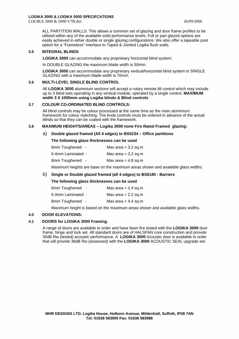
ALL PARTITION WALLS. This allows a common set of glazing and door frame profiles to be utilised within any of the available solid performance levels. Full or part glazed options are easily achieved in either double or single glazing configurations. We also offer a tapeable post option for a “Frameless” interface to Taped & Jointed Logika flush walls.
3.5 INTEGRAL BLINDS
LOGIKA 3000 can accommodate any proprietary horizontal blind system.
In DOUBLE GLAZING the maximum blade width is 50mm.
LOGIKA 3000 can accommodate any proprietary vertical/horizontal blind system in SINGLE GLAZING with a maximum blade width is 70mm.
3.6 MULTI-LEVEL SINGLE BLIND CONTROL
All LOGIKA 3000 aluminium sections will accept a rotary remote tilt control which may include up to 3 blind sets operating in any vertical module, operated by a single control. MAXIMUM width 3 X 1000mm using Logika blinds & Blind controls
3.7 COLOUR CO-ORDINATED BLIND CONTROLS:
All blind controls may be colour processed at the same time as the main aluminium framework for colour matching. The knob controls must be ordered in advance of the actual blinds so that they can be coated with the framework.
3.8 MAXIMUM HEIGHTS/AREAS – Logika 3000 none Fire Rated Framed glazing:
a) Double glazed framed (All 4 edges) to BS5234 – Office partitions
The following glass thicknesses can be used
6mm Toughened - Max area = 3.2 sq.m
6.4mm Laminated - Max area = 3.2 sq.m
8mm Toughened - Max area = 4.8 sq.m
Maximum heights are base on the maximum areas shown and available glass widths.
b) Single or Double glazed framed (all 4 edges) to BS6180 - Barriers
The following glass thicknesses can be used
6mm Toughened - Max area = 2.4 sq.m
6.4mm Laminated - Max area = 2.2 sq.m
8mm Toughened - Max area = 4.4 sq.m
Maximum height is based on the maximum areas shown and available glass widths.
4.0 DOOR ELEVATIONS:
4.1 DOORS for LOGIKA 3000 Framing.
A range of doors are available to order and have been fire tested with the LOGIKA 3000 door frame, hinge and lock set. All standard doors are of HALSPAN core construction and provide 30dB Rw (tested) acoustic performance. A LOGIKA 3000 Acoustic door is available to order that will provide 36dB Rw (assessed) with the LOGIKA 3000 ACOUSTIC SEAL upgrade set.
LOGIKA 3000 & LOGIKA 5000 SPECIFCATIONS LOGIKA 3000 & 5000-V7B.doc 26/09/2006
MHR DESIGNS LTD. Logika House, Holborn Avenue, Mildenhall, Suffolk, IP28 7AN Tel: 01638 583900 Fax: 01638 583988
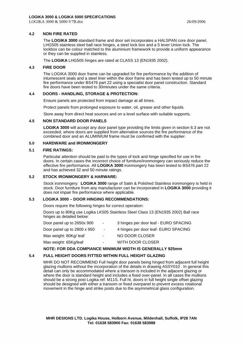
4.2 NON FIRE RATED
The LOGIKA 3000 standard frame and door set incorporates a HALSPAN core door panel, LHG505 stainless steel ball race hinges, a steel lock box and a 5 lever Union lock. The lockbox can be colour matched to the aluminium framework to provide a uniform appearance or they can be supplied in stainless.
The LOGIKA LHG505 hinges are rated at CLASS 13 (EN1935 2002).
4.3 FIRE DOOR
The LOGIKA 3000 door frame can be upgraded for fire performance by the addition of intumescent seals and a steel liner within the door frame and has been tested up to 50 minute fire performance under BS476 part 22 using a specialist door panel construction. Standard fire doors have been tested to 30minutes under the same criteria.
4.4 DOORS - HANDLING, STORAGE & PROTECTION:
Ensure panels are protected from impact damage at all times.
Protect panels from prolonged exposure to water, oil, grease and other liquids.
Store away from direct heat sources and on a level surface with suitable supports.
4.5 NON STANDARD DOOR PANELS
LOGIKA 3000 will accept any door panel type providing the limits given in section 6.3 are not exceeded, where doors are supplied from alternative sources the fire performance of the combined door and an ALUMINIUM frame must be confirmed with the supplier.
5.0 HARDWARE and IRONMONGERY
5.1 FIRE RATINGS:
Particular attention should be paid to the types of lock and hinge specified for use in fire doors. In certain cases the incorrect choice of furniture/ironmongery can seriously reduce the effective fire performance. All LOGIKA 3000 ironmongery has been tested to BS476 part 22 and has achieved 32 and 50 minute ratings.
5.2 STOCK IRONMONGERY & HARWARE:
Stock ironmongery: LOGIKA 3000 range of Satin & Polished Stainless ironmongery is held in stock. Door furniture from any manufacturer can be incorporated in LOGIKA 3000 providing it does not impair fire performance where applicable.
5.3 LOGIKA 3000 – DOOR HINGING RECOMMENDATIONS:
Doors require the following hinges for correct operation:
Doors up to 80Kg use Logika LK505 Stainless Steel Class 13 (EN1935 2002) Ball race hinges as detailed below:
Door panel up to 2650x 900 - 3 hinges per door leaf - EURO SPACING
Door panel up to 2800 x 950 - 4 hinges per door leaf- EURO SPACING
Max weight: 80Kg/ leaf - NO DOOR CLOSER
Max weight: 65Kg/leaf - WITH DOOR CLOSER
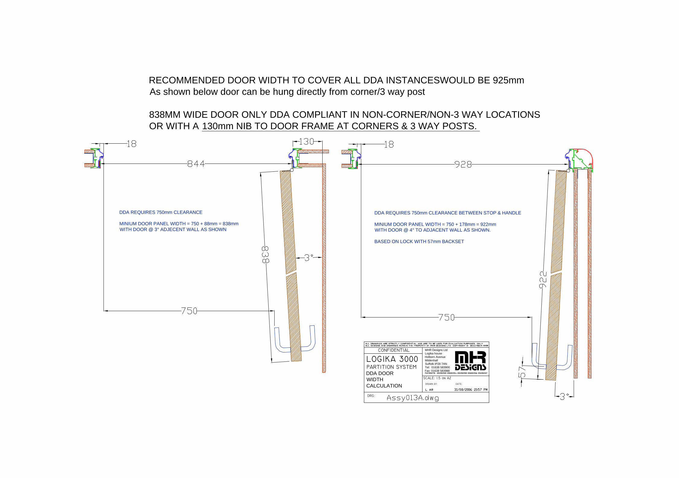
NOTE: FOR DDA COMPIANCE MINIMUM WIDTH IS GENERALLY 925mm
5.4 FULL HEIGHT DOORS FITTED WITHIN FULL HEIGHT GLAZING
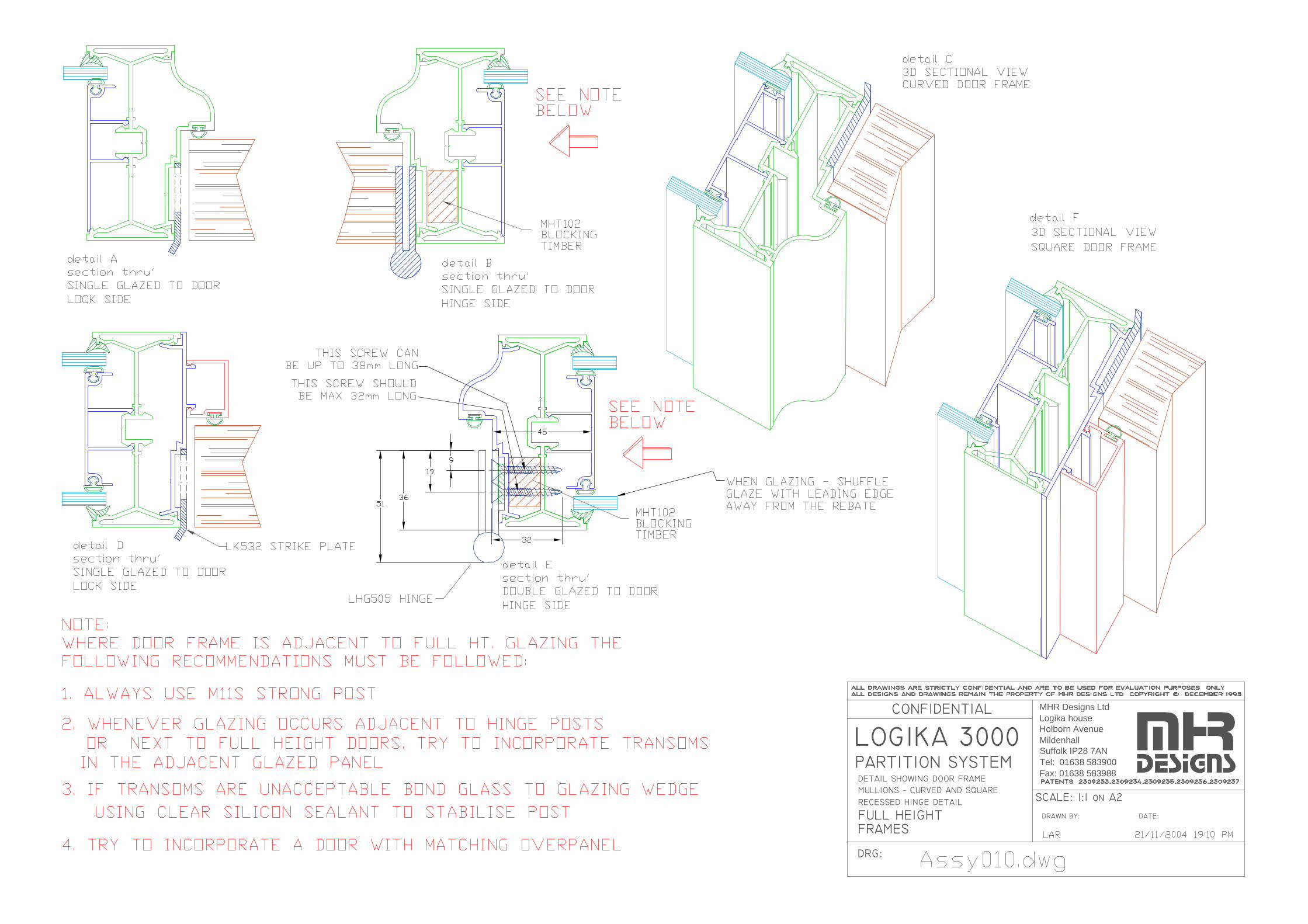
MHR DO NOT RECOMMEND Full height door panels being hinged from adjacent full height glazing mullions without the incorporation of the details in drawing ASSY010 . In general this detail can only be accommodated where a transom is included in the adjacent glazing or where the door is standard height and includes a fixed over-panel. In all cases the mullions should be a strong post Logika ref: M11S. Full ht. doors in full height single offset glazing should be designed with either a transom or fixed overpanel to prevent excess rotational movement in the hinge and strike posts due to the asymmetrical glass configuration.
LOGIKA 3000 & LOGIKA 5000 SPECIFCATIONS LOGIKA 3000 & 5000-V7B.doc 26/09/2006
MHR DESIGNS LTD. Logika House, Holborn Avenue, Mildenhall, Suffolk, IP28 7AN Tel: 01638 583900 Fax: 01638 583988
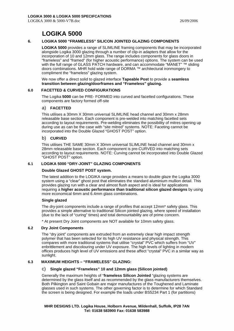
LOGIKA 5000 6. LOGIKA 5000 “FRAMELESS” SILICON JOINTED GLAZING COMPONENTS
LOGIKA 5000 provides a range of SLIMLINE framing components that may be incorporated alongside Logika 3000 glazing through a number of clip-in adapters that allow for the incorporation of 10 and 12mm glass. The range includes components for glass doors in “frameless” and “framed” (for higher acoustic performance) options. The system can be used with the full range of GLASS PATCH hardware, and can accommodate “MANET” ™ sliding doors combinations. MHR hold wide range of DORMA ™ architectural ironmongery to compliment the “frameless” glazing system.
We now offer a direct solid to glazed interface Tapeable Post to provide a seamless transition between glazing/doorframes and “Frameless” glazing.
6.0 FACETTED & CURVED CONFIGURATIONS
The Logika 5000 can be PRE- FORMED into curved and facetted configurations. These components are factory formed off-site
a) FACETTED
This utilises a 30mm X 30mm universal SLIMLINE head channel and 30mm x 28mm releasable base section. Each component is pre-welded into matching facetted sets according to layout requirements. Pre-welding eliminates the possibility of mitres opening up during use as can be the case with “site mitred” systems. NOTE: Faceting cannot be incorporated into the Double Glazed “GHOST POST” option.
b) CURVED
This utilises THE SAME 30mm X 30mm universal SLIMLINE head channel and 30mm x 28mm releasable base section. Each component is pre-CURVED into matching sets according to layout requirements. NOTE: Curving cannot be incorporated into Double Glazed “GHOST POST” option.
6.1 LOGIKA 5000 “DRY-JOINT” GLAZING COMPONENTS
Double Glazed GHOST POST system.
The latest addition to the LOGIKA range provides a means to double glaze the Logika 3000 system using a “clear” ghost post that eliminates the standard aluminium mullion detail. This provides glazing run with a clear and almost flush aspect and is ideal for applications requiring a higher acoustic performance than traditional silicon glazed designs by using more economical 6mm and 6.4mm glass combinations.
Single glazed
The dry-joint components include a range of profiles that accept 12mm* safety glass. This provides a simple alternative to traditional Silicon jointed glazing, where speed of installation (due to the lack of “curing” times) and total demountability are of prime concern.
* At present Dry Joint components are NOT available for 10mm safety glass.
6.2 Dry Joint Components
The “dry joint” components are extruded from an extremely clear high impact strength polymer that has been selected for its high UV resistance and physical strength. This compares with more traditional systems that utilise “crystal” PVC which suffers from “UV” enbrittlement and discolouring under UV exposure. The high levels of lighting in modern offices produces high level of UV emissions and these affect “crystal” PVC in a similar way as sunlight.
6.3 MAXIMUM HEIGHTS – “FRAMELESS” GLAZING:
c) Single glazed “Frameless” 10 and 12mm glass (Silicon jointed)
Generally the maximum heights of “frameless Silicon Jointed “glazing systems are determined by the glass itself and as recommended by the glass manufacturers themselves. Both Pilkington and Saint Gobain are major manufactures of the Toughened and Laminate glasses used in such systems. The other governing factor is to determine for which Standard the screen is being designed. For example the loads under BS5234 Part 1 (for partitions)
LOGIKA 3000 & LOGIKA 5000 SPECIFCATIONS LOGIKA 3000 & 5000-V7B.doc 26/09/2006
MHR DESIGNS LTD. Logika House, Holborn Avenue, Mildenhall, Suffolk, IP28 7AN Tel: 01638 583900 Fax: 01638 583988
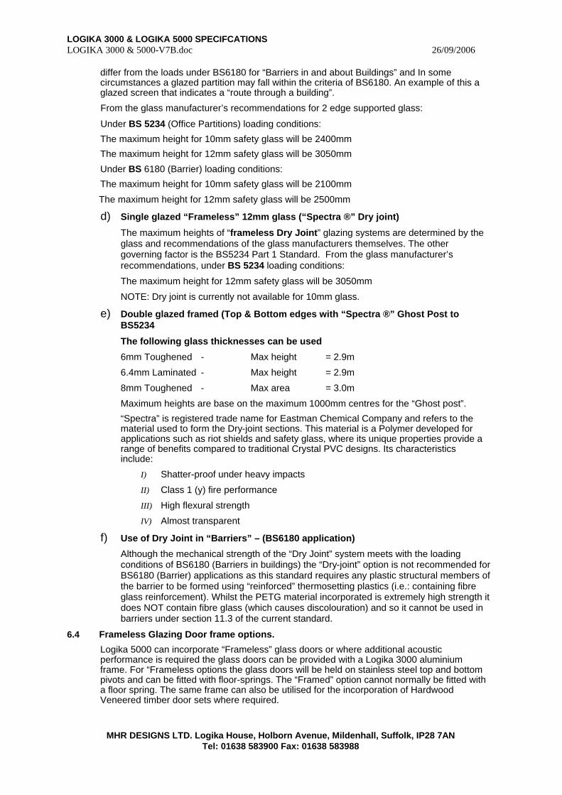
differ from the loads under BS6180 for “Barriers in and about Buildings” and In some circumstances a glazed partition may fall within the criteria of BS6180. An example of this a glazed screen that indicates a “route through a building”.
From the glass manufacturer’s recommendations for 2 edge supported glass:
Under BS 5234 (Office Partitions) loading conditions:
The maximum height for 10mm safety glass will be 2400mm
The maximum height for 12mm safety glass will be 3050mm
Under BS 6180 (Barrier) loading conditions:
The maximum height for 10mm safety glass will be 2100mm
The maximum height for 12mm safety glass will be 2500mm
d) Single glazed “Frameless” 12mm glass (“Spectra ®” Dry joint)
The maximum heights of “frameless Dry Joint” glazing systems are determined by the glass and recommendations of the glass manufacturers themselves. The other governing factor is the BS5234 Part 1 Standard. From the glass manufacturer’s recommendations, under BS 5234 loading conditions:
The maximum height for 12mm safety glass will be 3050mm
NOTE: Dry joint is currently not available for 10mm glass.
e) Double glazed framed (Top & Bottom edges with “Spectra ®” Ghost Post to BS5234
The following glass thicknesses can be used
6mm Toughened - Max height = 2.9m
6.4mm Laminated - Max height = 2.9m
8mm Toughened - Max area = 3.0m
Maximum heights are base on the maximum 1000mm centres for the “Ghost post”.
“Spectra” is registered trade name for Eastman Chemical Company and refers to the material used to form the Dry-joint sections. This material is a Polymer developed for applications such as riot shields and safety glass, where its unique properties provide a range of benefits compared to traditional Crystal PVC designs. Its characteristics include:
I) Shatter-proof under heavy impacts
II) Class 1 (y) fire performance
III) High flexural strength
IV) Almost transparent
f) Use of Dry Joint in “Barriers” – (BS6180 application)
Although the mechanical strength of the “Dry Joint” system meets with the loading conditions of BS6180 (Barriers in buildings) the “Dry-joint” option is not recommended for BS6180 (Barrier) applications as this standard requires any plastic structural members of the barrier to be formed using “reinforced” thermosetting plastics (i.e.: containing fibre glass reinforcement). Whilst the PETG material incorporated is extremely high strength it does NOT contain fibre glass (which causes discolouration) and so it cannot be used in barriers under section 11.3 of the current standard.
6.4 Frameless Glazing Door frame options.
Logika 5000 can incorporate “Frameless” glass doors or where additional acoustic performance is required the glass doors can be provided with a Logika 3000 aluminium frame. For “Frameless options the glass doors will be held on stainless steel top and bottom pivots and can be fitted with floor-springs. The “Framed” option cannot normally be fitted with a floor spring. The same frame can also be utilised for the incorporation of Hardwood Veneered timber door sets where required.
LOGIKA 3000 & LOGIKA 5000 SPECIFCATIONS LOGIKA 3000 & 5000-V7B.doc 26/09/2006
MHR DESIGNS LTD. Logika House, Holborn Avenue, Mildenhall, Suffolk, IP28 7AN Tel: 01638 583900 Fax: 01638 583988
DDA Legislation and Frameless Doors
Under current legislation fully “frameless” glass doors may not comply with the requirements of the “Design of Buildings and their approaches to meet the needs of disabled people Code of Practice” (known as the DDA standards). To comply, all doors should have contrasting perimeter finish to make the door more visible within the surrounding glass.

LOGIKA 3000 & LOGIKA 5000 SPECIFCATIONS LOGIKA 3000 & 5000-V7B.doc 26/09/2006
MHR DESIGNS LTD. Logika House, Holborn Avenue, Mildenhall, Suffolk, IP28 7AN Tel: 01638 583900 Fax: 01638 583988
7.0 MAXIMUM HEIGHTS - physical data: (Updated 05/09/2003)
7.1 SOLID ELEVATIONS
SUMMARY RATINGS & HEIGHT LIMITS - LOGIKA SOLID PARTITIONS – 12mm BOARDS
HEIGHTS based on DEFELECTION LIMITS FOR A MEDIUM DUTY PARTITION (See BS5234 Part1)
BO
AR
D
BO
AR
D T
YP
E
BO
AR
D J
OIN
T
DE
TA
IL
ST
UD
BO
XE
D
ST
UD
C
EN
TR
ES
mm
HE
AD
& B
AS
E
TR
AC
K
LA
YE
RS
per
F
AC
E
30m
m
MIN
ER
AL
W
OO
L Q
UIL
T
FIR
E m
inu
tes
SO
UN
D d
B R
w
MA
X H
EIG
HT
12.5 STD T,C* 48 N 50x40 1 N 30 35
12.5 STD T,C* 48 N 50x40 1 Y 30 42
12.5 fireline T,C* 48 N
600
50x40 1 Y 60 42
3200
12.5 STD T,C* 48 N 50x40 1 N 30 35
12.5 STD T,C* 48 N 50x40 1 Y 30 42
12.5 fireline T,C* 48 N
400
50x40 1 Y 60 42
3500
12.5 STD T,C* 48 N 50x40 1 N 30 35
12.5 STD T,C* 48 N 50x40 1 Y 30 42
12.5 fireline T,C* 48 N
300
50x40 1 Y 60 42
4000
12.5 STD T,C* 48 Y 50x40 1 N 30 35
12.5 STD T,C* 48 Y 50x40 1 Y 30 42
12.5 fireline T,C* 48 Y
600
50x40 1 Y 60 42
3600
12.5 STD T,C* 48 Y 50x40 1 N 30 35
12.5 STD T,C* 48 Y 50x40 1 Y 30 42
12.5 fireline T,C* 48 Y
400
50x40 1 Y 60 42
4000
12.5 STD T,C* 48 Y 50x40 1 N 30 35
12.5 STD T,C* 48 Y 50x40 1 Y 30 42
12.5 fireline T,C* 48 Y
300
50x40 1 Y 60 42
4800
LOGIKA 3000 & LOGIKA 5000 SPECIFCATIONS LOGIKA 3000 & 5000-V7B.doc 26/09/2006
MHR DESIGNS LTD. Logika House, Holborn Avenue, Mildenhall, Suffolk, IP28 7AN Tel: 01638 583900 Fax: 01638 583988
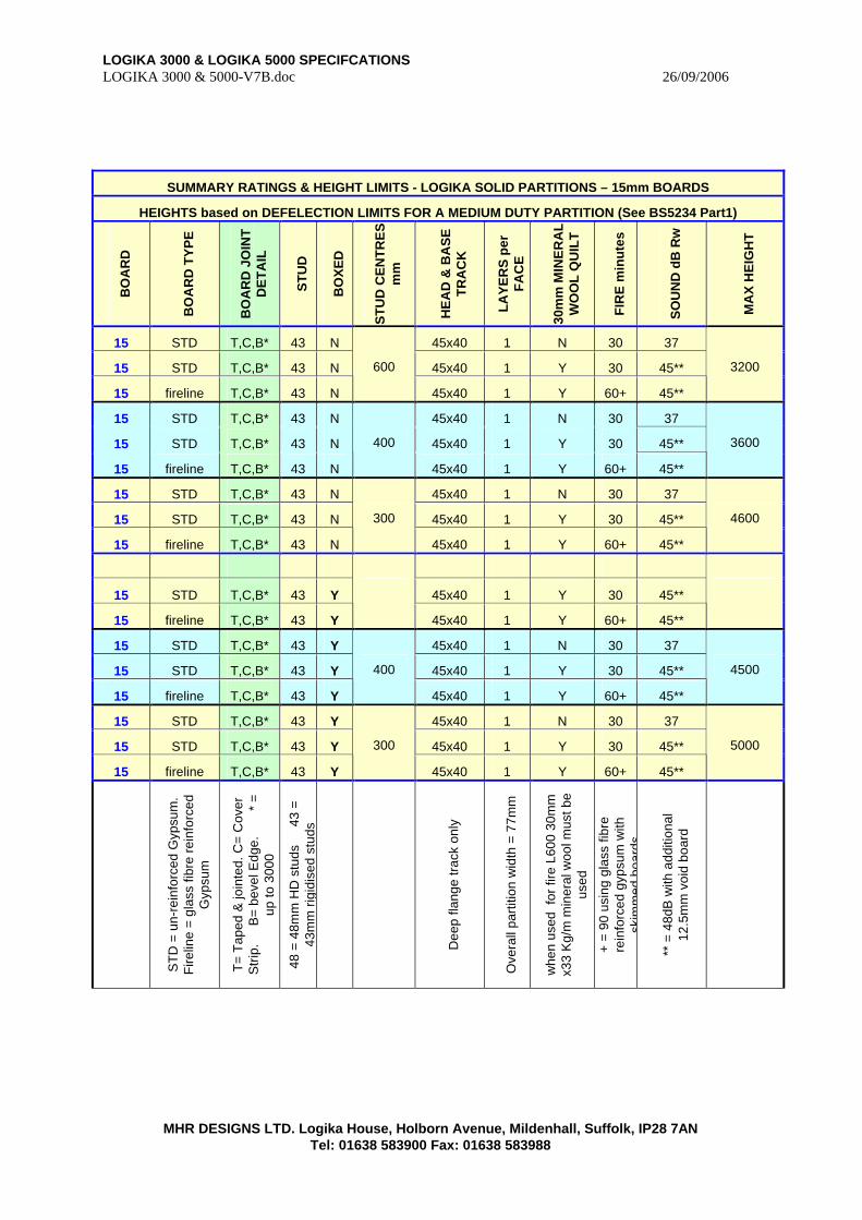
SUMMARY RATINGS & HEIGHT LIMITS - LOGIKA SOLID PARTITIONS – 15mm BOARDS
HEIGHTS based on DEFELECTION LIMITS FOR A MEDIUM DUTY PARTITION (See BS5234 Part1)
BO
AR
D
BO
AR
D T
YP
E
BO
AR
D J
OIN
T
DE
TA
IL
ST
UD
BO
XE
D
ST
UD
CE
NT
RE
S
mm
HE
AD
& B
AS
E
TR
AC
K
LA
YE
RS
per
F
AC
E
30m
m M
INE
RA
L
WO
OL
QU
ILT
FIR
E m
inu
tes
SO
UN
D d
B R
w
MA
X H
EIG
HT
15 STD T,C,B* 43 N 45x40 1 N 30 37
15 STD T,C,B* 43 N 45x40 1 Y 30 45**
15 fireline T,C,B* 43 N
600
45x40 1 Y 60+ 45**
3200
15 STD T,C,B* 43 N 45x40 1 N 30 37
15 STD T,C,B* 43 N 45x40 1 Y 30 45**
15 fireline T,C,B* 43 N
400
45x40 1 Y 60+ 45**
3600
15 STD T,C,B* 43 N 45x40 1 N 30 37
15 STD T,C,B* 43 N 45x40 1 Y 30 45**
15 fireline T,C,B* 43 N
300
45x40 1 Y 60+ 45**
4600
15 STD T,C,B* 43 Y 45x40 1 Y 30 45**
15 fireline T,C,B* 43 Y
45x40 1 Y 60+ 45**
15 STD T,C,B* 43 Y 45x40 1 N 30 37
15 STD T,C,B* 43 Y 45x40 1 Y 30 45**
15 fireline T,C,B* 43 Y
400
45x40 1 Y 60+ 45**
4500
15 STD T,C,B* 43 Y 45x40 1 N 30 37
15 STD T,C,B* 43 Y 45x40 1 Y 30 45**
15 fireline T,C,B* 43 Y
300
45x40 1 Y 60+ 45**
5000
ST
D =
un-
rein
forc
ed G
ypsu
m.
Fire
line
= gl
ass
fibre
rei
nfor
ced
Gyp
sum
T=
Tap
ed &
join
ted.
C=
Cov
er
Str
ip.
B
= be
vel E
dge.
* =
up
to 3
000
48 =
48m
m H
D s
tuds
4
3 =
43m
m r
igid
ised
stu
ds
Dee
p fla
nge
trac
k on
ly
Ove
rall
part
ition
wid
th =
77m
m
whe
n us
ed f
or fi
re L
600
30m
m
x33
Kg/
m m
iner
al w
ool m
ust b
e us
ed
+ =
90 u
sing
gla
ss fi
bre
rein
forc
ed g
ypsu
m w
ith
skim
med
boa
rds
** =
48d
B w
ith a
dditi
onal
12
.5m
m v
oid
boar
d
LOGIKA 3000 & LOGIKA 5000 SPECIFCATIONS LOGIKA 3000 & 5000-V7B.doc 26/09/2006
MHR DESIGNS LTD. Logika House, Holborn Avenue, Mildenhall, Suffolk, IP28 7AN Tel: 01638 583900 Fax: 01638 583988
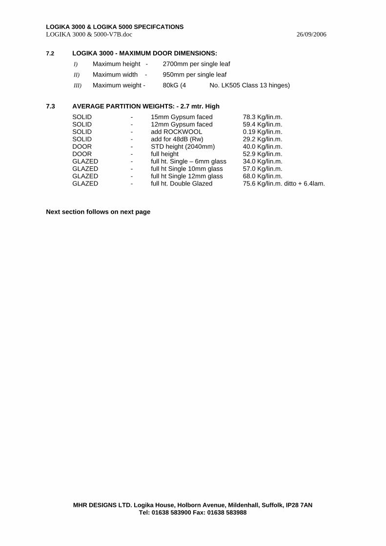
7.2 LOGIKA 3000 - MAXIMUM DOOR DIMENSIONS:
I) Maximum height - 2700mm per single leaf
II) Maximum width - 950mm per single leaf
III) Maximum weight - 80kG (4 No. LK505 Class 13 hinges)
7.3 AVERAGE PARTITION WEIGHTS: - 2.7 mtr. High
SOLID - 15mm Gypsum faced 78.3 Kg/lin.m. SOLID - 12mm Gypsum faced 59.4 Kg/lin.m. SOLID - add ROCKWOOL 0.19 Kg/lin.m. SOLID - add for 48dB (Rw) 29.2 Kg/lin.m. DOOR - STD height (2040mm) 40.0 Kg/lin.m. DOOR - full height 52.9 Kg/lin.m. GLAZED - full ht. Single – 6mm glass 34.0 Kg/lin.m. GLAZED - full ht Single 10mm glass 57.0 Kg/lin.m. GLAZED - full ht Single 12mm glass 68.0 Kg/lin.m. GLAZED - full ht. Double Glazed 75.6 Kg/lin.m. ditto + 6.4lam.
Next section follows on next page
LOGIKA 3000 & LOGIKA 5000 SPECIFCATIONS LOGIKA 3000 & 5000-V7B.doc 26/09/2006
MHR DESIGNS LTD. Logika House, Holborn Avenue, Mildenhall, Suffolk, IP28 7AN Tel: 01638 583900 Fax: 01638 583988
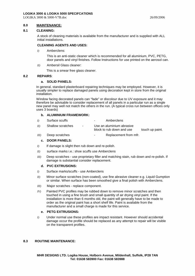
8.0 MAINTENANCE:
8.1 CLEANING:
A stock of cleaning materials is available from the manufacturer and is supplied with ALL initial installations.
CLEANING AGENTS AND USES:
I) Amberclens:
This is an anti-static cleaner which is recommended for all aluminium, PVC, PETG, door panels and vinyl finishes. Follow Instructions for use printed on the aerosol can.
II) Ambersil Glass cleaner:
This is a smear free glass cleaner.
8.2 REPAIRS:
a. SOLID PANELS:
In general, standard plasterboard repairing techniques may be employed. However, it is usually simpler to replace damaged panels using decoration kept in store from the original installation.
Window facing decorated panels can “fade” or discolour due to UV exposure and it may therefore be advisable to consider replacement of all panels in a particular run as a single new panel may well not match the others in the run. (A typical cross run between offices only uses 3 boards)
b. ALUMINIUM FRAMEWORK:
I) Surface scuffs - Amberclens
II) Shallow scratches - Use an aluminium abrasive block to rub down and use touch up paint.
III) Deep scratches - Replacement from mfr.
c. DOOR PANELS:
I) If damage is slight then rub down and re-polish.
II) surface marks i.e.: shoe scuffs use Amberclens
III) Deep scratches - use proprietary filler and matching stain, rub down and re-polish. If damage is substantial consider replacement.
d. PVC EXTRUSIONS:
I) Surface marks/scuffs - use Amberclens
II) Minor surface scratches (non-coated), use fine abrasive cleaner e.g. Liquid Gumption or similar. When surface has been smoothed give a final polish with Amberclens.
III) Major scratches - replace component.
IV) Painted PVC profiles may be rubbed down to remove minor scratches and then touched in using a fine brush and small quantity of air drying vinyl paint. If the installation is more than 6 months old, the paint will generally have to be made to order as the original paint has a short shelf life. Paint is available from the manufacturer and a small charge is made for this service.
e. PETG EXTRUSIONS:
I) Under normal use these profiles are impact resistant. However should accidental damage occur the profile should be replaced as any attempt to repair will be visible on the transparent profiles.
8.3 ROUTINE MAINTENANCE:
LOGIKA 3000 & LOGIKA 5000 SPECIFCATIONS LOGIKA 3000 & 5000-V7B.doc 26/09/2006
MHR DESIGNS LTD. Logika House, Holborn Avenue, Mildenhall, Suffolk, IP28 7AN Tel: 01638 583900 Fax: 01638 583988
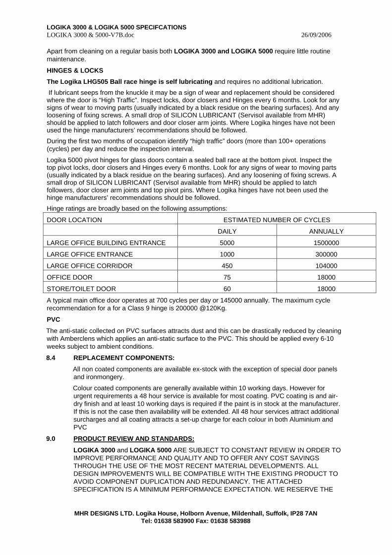
Apart from cleaning on a regular basis both LOGIKA 3000 and LOGIKA 5000 require little routine maintenance.
HINGES & LOCKS
The Logika LHG505 Ball race hinge is self lubricating and requires no additional lubrication.
If lubricant seeps from the knuckle it may be a sign of wear and replacement should be considered where the door is “High Traffic”. Inspect locks, door closers and Hinges every 6 months. Look for any signs of wear to moving parts (usually indicated by a black residue on the bearing surfaces). And any loosening of fixing screws. A small drop of SILICON LUBRICANT (Servisol available from MHR) should be applied to latch followers and door closer arm joints. Where Logika hinges have not been used the hinge manufacturers’ recommendations should be followed.
During the first two months of occupation identify “high traffic” doors (more than 100+ operations (cycles) per day and reduce the inspection interval.
Logika 5000 pivot hinges for glass doors contain a sealed ball race at the bottom pivot. Inspect the top pivot locks, door closers and Hinges every 6 months. Look for any signs of wear to moving parts (usually indicated by a black residue on the bearing surfaces). And any loosening of fixing screws. A small drop of SILICON LUBRICANT (Servisol available from MHR) should be applied to latch followers, door closer arm joints and top pivot pins. Where Logika hinges have not been used the hinge manufacturers’ recommendations should be followed.
Hinge ratings are broadly based on the following assumptions:
DOOR LOCATION ESTIMATED NUMBER OF CYCLES
DAILY ANNUALLY
LARGE OFFICE BUILDING ENTRANCE 5000 1500000
LARGE OFFICE ENTRANCE 1000 300000
LARGE OFFICE CORRIDOR 450 104000
OFFICE DOOR 75 18000
STORE/TOILET DOOR 60 18000
A typical main office door operates at 700 cycles per day or 145000 annually. The maximum cycle recommendation for a for a Class 9 hinge is 200000 @120Kg.
PVC
The anti-static collected on PVC surfaces attracts dust and this can be drastically reduced by cleaning with Amberclens which applies an anti-static surface to the PVC. This should be applied every 6-10 weeks subject to ambient conditions.
8.4 REPLACEMENT COMPONENTS:
All non coated components are available ex-stock with the exception of special door panels and ironmongery.
Colour coated components are generally available within 10 working days. However for urgent requirements a 48 hour service is available for most coating. PVC coating is and air-dry finish and at least 10 working days is required if the paint is in stock at the manufacturer. If this is not the case then availability will be extended. All 48 hour services attract additional surcharges and all coating attracts a set-up charge for each colour in both Aluminium and PVC
9.0 PRODUCT REVIEW AND STANDARDS:
LOGIKA 3000 and LOGIKA 5000 ARE SUBJECT TO CONSTANT REVIEW IN ORDER TO IMPROVE PERFORMANCE AND QUALITY AND TO OFFER ANY COST SAVINGS THROUGH THE USE OF THE MOST RECENT MATERIAL DEVELOPMENTS. ALL DESIGN IMPROVEMENTS WILL BE COMPATIBLE WITH THE EXISTING PRODUCT TO AVOID COMPONENT DUPLICATION AND REDUNDANCY. THE ATTACHED SPECIFICATION IS A MINIMUM PERFORMANCE EXPECTATION. WE RESERVE THE
LOGIKA 3000 & LOGIKA 5000 SPECIFCATIONS LOGIKA 3000 & 5000-V7B.doc 26/09/2006
MHR DESIGNS LTD. Logika House, Holborn Avenue, Mildenhall, Suffolk, IP28 7AN Tel: 01638 583900 Fax: 01638 583988
RIGHT TO UPGRADE AND ALTER THIS SPECIFICATION WHILST MAINTAINING THIS MINIMUM PERFORMANCE. WE WILL ENDEAVOUR TO SUPPORT ANY SPECIAL DESIGN REQUIREMENTS PROVIDING THAT THE DESIGN CRITERIA ARE IN ACCORDANCE WITH THE LATEST REGULATIONS AND SAFETY STANDARDS. WE WILL NOT SUPPORT DESIGN REQUIREMENTS WHICH DO NOT SATISFY SAFETY STANDARDS OR DO NOT COMPLY WITH BRITISH OR EUROPEAN STANDARDS. ALL MANUFACTURING AND FINISHING PROCESSES USED IN THE LOGIKA 3000 & 5000 SYSTEMS ARE BS5750 APPROVED.
9.1 MANUFACTURED IN THE UK BY:
MHR DESIGNS LTD. e-mail : [email protected]
Address & telephone Numbers: See bottom of page. AVAILABLE THROUGH YOUR LOCAL APPROVED CONTRACTOR:

LOGIKA 3000 & LOGIKA 5000 SPECIFCATIONS LOGIKA 3000 & 5000-V7B.doc 26/09/2006
MHR DESIGNS LTD. Logika House, Holborn Avenue, Mildenhall, Suffolk, IP28 7AN Tel: 01638 583900 Fax: 01638 583988
APPENDIX 1
DETAIL DRAWINGS
LOGIKA 3000 & LOGIKA 5000 SPECIFCATIONS LOGIKA 3000 & 5000-V7B.doc 26/09/2006
MHR DESIGNS LTD. Logika House, Holborn Avenue, Mildenhall, Suffolk, IP28 7AN Tel: 01638 583900 Fax: 01638 583988
Appendix 1
Section A
LOGIKA 30000

LOGIKA 3000 & LOGIKA 5000 SPECIFCATIONS LOGIKA 3000 & 5000-V7B.doc 26/09/2006
MHR DESIGNS LTD. Logika House, Holborn Avenue, Mildenhall, Suffolk, IP28 7AN Tel: 01638 583900 Fax: 01638 583988
SECTION A - LOGIKA 3000
COMPONENTS:
ASSY001 ALUMINIUM COMPONENTS, GASKETS & SETTING BLOCKS
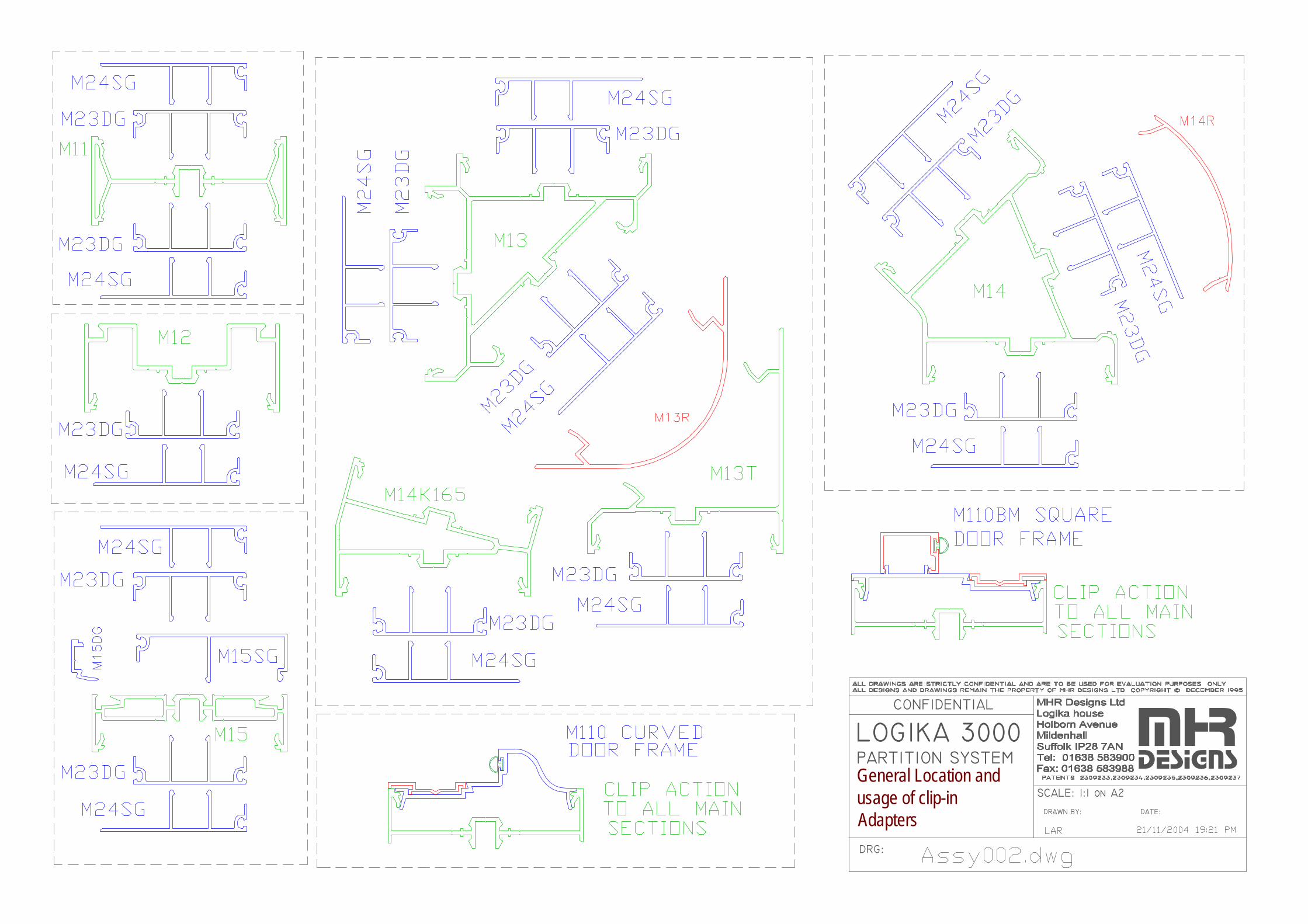
ASSY002 ALUMINIUM COMPONENTS - USAGE
ASSY003 BRACKETS - LOCATION & FIXING
ASSEMBLY DRAWINGS:
ASSY003A CONCEALED FIX BOARDS & CLIP LOCATION
ASSY003B 48Db SOLID CONSTRUCTION – BEVEL EDGE BOARDS
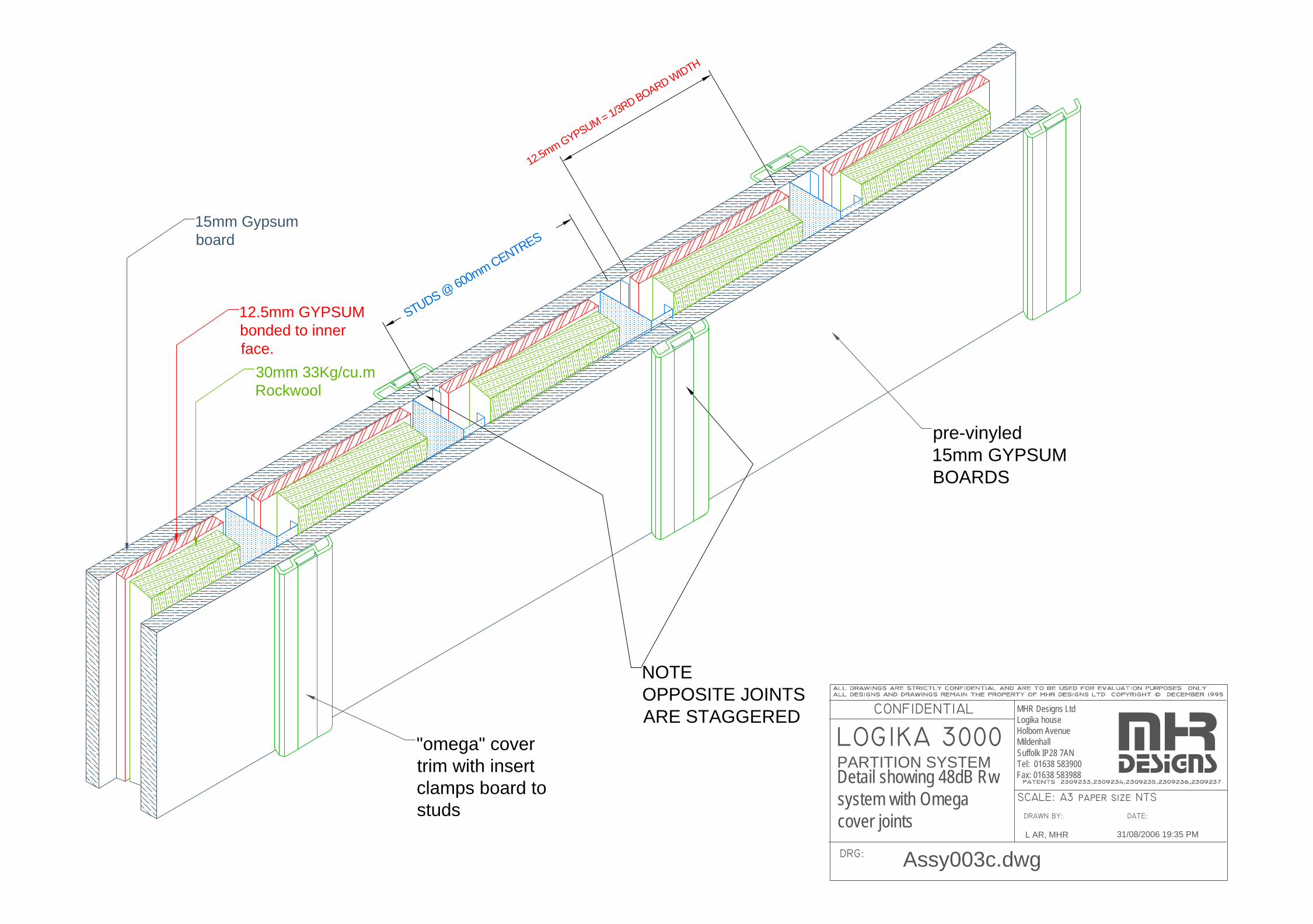
ASSY003C 48Db SOLID CONSTRUCTION – OMEGA TRIM OPTION
ASSY003D ACOUSTIC OPTIONS -SOLID CONSTRUCTION
ASSY004 ANSCILIARY COMPONENTS AND STEEL SECTIONS
ASSY004A REDUCER POST TO WINDOW MULLION
ASSY004B M11 / REDUCER POST TO WINDOW MULLION
ASSY005 TYPICAL SECTIONS THRU’ DOOR HT. SOLID & DOOR. HT. DOUBLE GLAZING
ASSY005A TYPICAL SECTIONS THRU’ F.HT .DOUBLE GLAZING
ASSY005B DOUBLE GLAZED WITH FRAMED DOUBLE GLAZED DOOR
ASSY005C DOUBLE GLAZED WITH FRAMED DOUBLE GLAZED DOOR WITH O/PANEL
ASSY005D SINGLE GLAZED FULL HEIGHT GLAZING
ASSY005E SINGLE GLAZED FULL HEIGHT WITH COMPRESSION HEAD
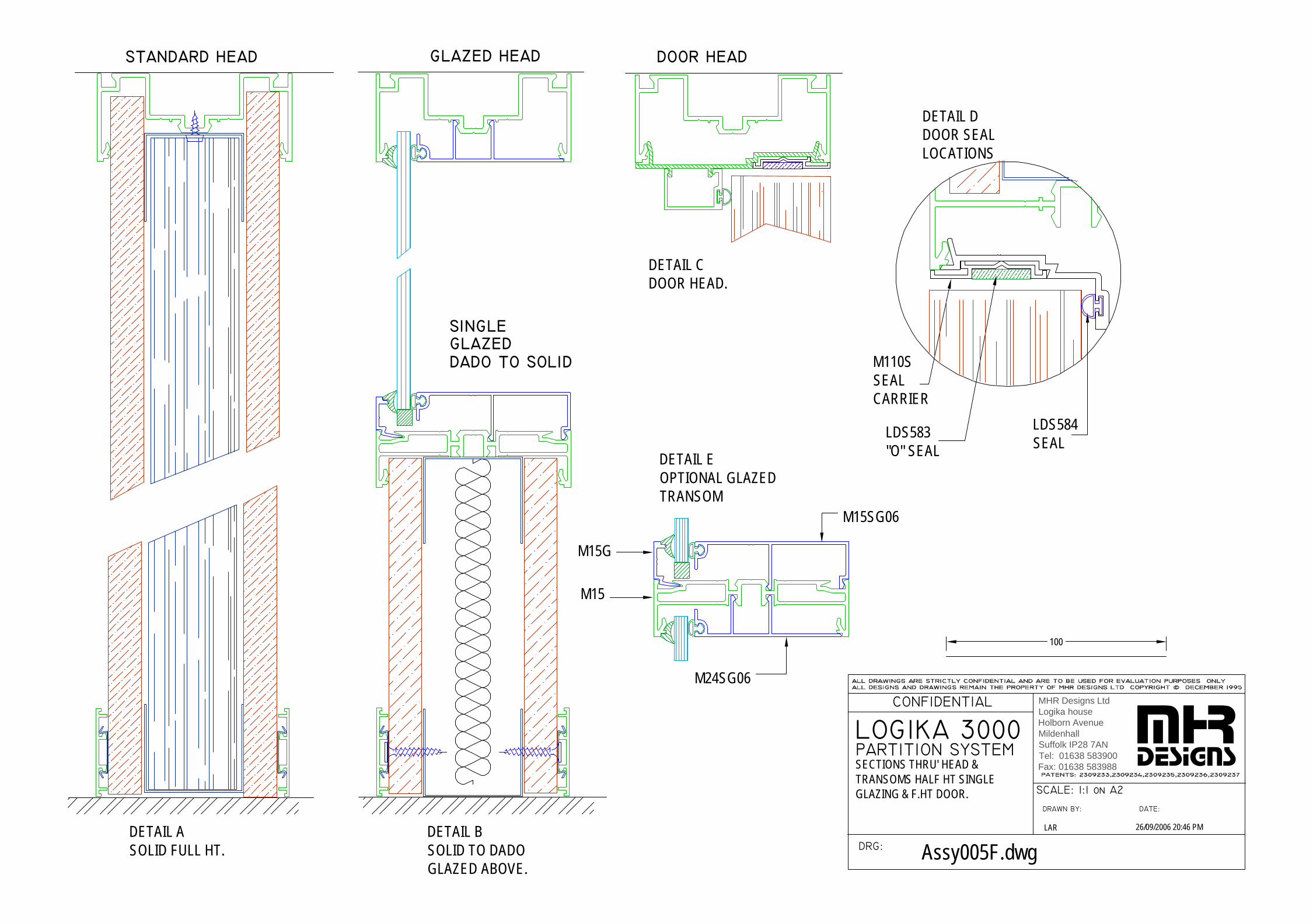
ASSY005F SINGLE GLAZED OVER DADO RAIL, SOLID BELOW
ASSY006 STD. CORNERS & THREE WAY JUNCTIONS
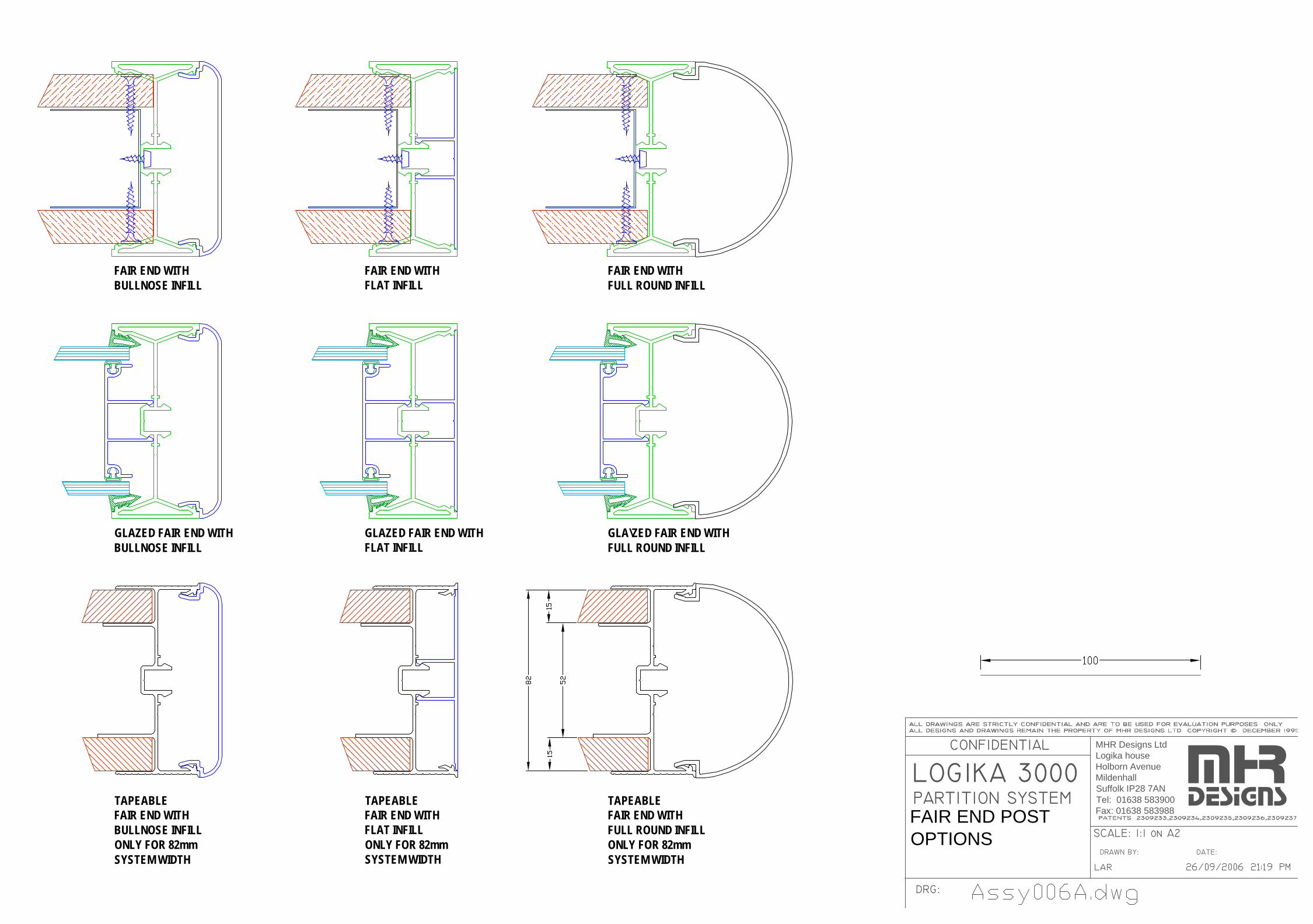
ASSY006A FAIR END OPTIONS
ASSY007 DOUBLE & SINGLE GLAZED MULLIONS
ASSY008 DOUBLE & SINGLE GLAZED TRANSOMS
ASSY008A 3D DOUBLE & SINGLE TRANSOMS
ASSY009 GLASS MEASUREMENT & INSTALLATION
ASSY010 FULL HT. DOOR FRAMES IN GLAZED RUNS
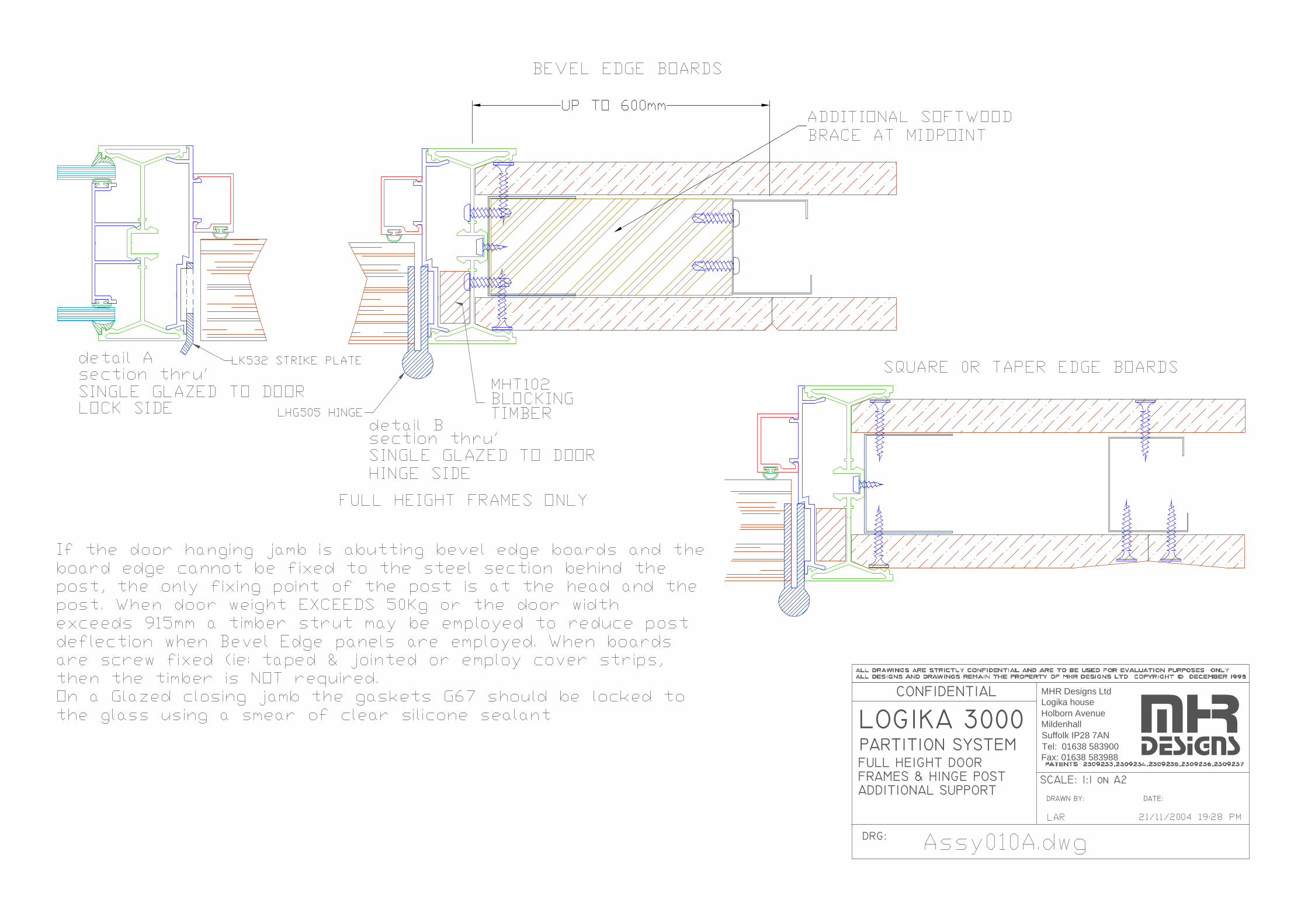
ASSY010A FULL HT. DOOR FRAMES IN VEE JOINT SOLID
ASSY010C ACOUSTIC DOOR TREATMENT (36dB)
ASSY011 STANDARD HT. DOOR MULLIONS
ASSY012 165° POST FOR FACETED LAYOUTS
ASSY012A 165° FACET POST SETTING OUT
ASSY013 DOOR FRAME SETTING OUT & DIMENSIONS
ASS013A DDA COMPLIANT DOOR WIDTHS
ASSY014 10/12mm GLASS DOOR WITHIN 6mm GLAZING
ASSY014B 10-12mm GLASS DOOR SETTING OUT & DIMENSIONS
ASS7015 BLIND CONTROL SITE PREPARATION
ASSY016 ELECTRICAL CONDUIT LOCATION
ASSY016A SWITCH POST WITH KOPEX CONDUIT AND HEAT SHRINK SHROUD
ASSY016B SWITCH POST “WIRES ONLY” INSTALLATION.
ASSY016C SWITCH POST – CONVERSION FROM “WIRE ONLY” TO KOPEX CONDUIT
ASSY016D ALTERNATIVE CABLE ROUTE FOR “WIRES ONLY” FEED
ASSY0016E “WIRES ONLY” FEED TO TWIN ROCKER SWITCHES
ASSY016F TWIN ROCKER SWITCHES VIA KOPEX CONDUIT
LOGIKA 3000 & LOGIKA 5000 SPECIFCATIONS LOGIKA 3000 & 5000-V7B.doc 26/09/2006
MHR DESIGNS LTD. Logika House, Holborn Avenue, Mildenhall, Suffolk, IP28 7AN Tel: 01638 583900 Fax: 01638 583988
ASSY017 FIRE RATED STD HT. DOOR FRAME
ASSY017A FIRE RATED PARTITION SUPPORT ABOVE SUSPENDED CEILING
ASSY017B FIRE RATED DOOR FRAME MULLIONS & TRANSOMS
ASSY018A FIRE RATED SINGLE GLAZING - SETTING OUT & INSTALLATION
ASSY018B FIRE RATED DOUBLE GLAZING - SETTING OUT & INSTALLATION
ASSY018C FIRE RATED CORNER JUNCTIONS

M12RRECESSEDHEAD/ABUTMENTCHANNEL
LDS590DOOR SEALSQUARE FRAME
M110BMSQUARE DOOR FRAME BASE MEMBER
M12HEAD/ABUTMENTCHANNEL
DOOR FRAMES AND POST CAPPINGS
STANDARD POSTS,HEADS/ABUTMENT CHANNELS
M125FLAT INFILL
FLUSH FRAMING POSTTO TAPED & JOINTED 82mm WALL
M53100TAPEABLE FLUSH GLAZING ADAPTERFOR LOGIKA 5000/3000 SOLIDMULLION POST/BULKHEAD TRANSOM.REQUIRES 52mm TRACK.50mm STUD+15mm BOARDS.BOARD FACE to BOARD FACE = 83mm
M110SSEAL CARRIERFOR ALL DOORFRAMES
LDS584DOOR FRAMESEAL INSERT
M123BULL-NOSE INFILL
88.5
8352
M110CURVED DOOR FRAME
LDS583DOOR SEALSTD FRAME
88.577
40
M11MAINPOST
M24CTR1212mm CENTREGLAZING BEAD
M24SG1212mm OFFSETGLAZING ADAPTER
M110SQSQUAREDOOR STOP
M15SSILL TO SOLIDADAPTER
G4BACK SEAL
G67WEDGE
G1010SETTINGBLOCK
26
DBL GLAZINGINNER
6mm GLAZING SECTIONS FOR SILLS/TRANSOMS
12mm GLAZING SECTIONS FOR SILLS/TRANSOMS
ALTERNATIVE 12mm GLAZING SILL CONFIGURATION
M13SQ90° SQUARE INFILL
M13T90° - 3 WAYADAPTER
M1390°CORNER/Y POST
M14K165165° FACET POST
M13R90° FULL RADIUS INFILL
STANDARD CORNER & 3WAYPOSTS (drawn 1/2scale ON A2)
M11RTROUND TRIMADAPTER FORMAIN POST
M11RCLCLIP
M14135°CORNER
/Y POST
M14R135°RADIUS
CORNER INFILL
12mm OFFSET SGL GLAZINGADAPTER - upper
M24SG1212mm OFFSETGLAZING ADAPTER
6mm OFFSET SGL GLAZING ADAPTER
GLAZINGBEAD
43
M24CTR1212mm CENTREGLAZING BEAD
M15CT1212mm CTR GLAZEDADAPTER
6mm OFFSET SGL GLAZINGADAPTER - upper
GLAZINGBEAD
M15 SILL/TRANSOM
GLAZINGBEAD
GLAZING BEAD
GASKETS & SETTING BLOCKS (not to scale)
M15 SILL/TRANSOM
M15 SILL/TRANSOM M15 SILL/TRANSOM
M15 SILL/TRANSOM M15 SILL/TRANSOM
M15 SILL/TRANSOM
ABUTMENT REDUCER M120/1REDUCER WINDOWCHANNEL
M120/2REDUCER to SOLIDADAPTER
M120/3REDUCERTRIM
M31922BULKHEADCHANNEL
G67FWEDGE
LOGIKA 3000 mhrdesigns
MHR DESIGNS LTD. LOGIKA HOUSE, HOLBORN AVENUE, MILDENHALL, SUFFOLK IP28 7ANTel: 01638 583900 Fax: 01683 583988 email: [email protected]
INIT DATE
MHR DESIGNS LTD. LOGIKA HOUSE, HOLBORN AVENUE, MILDENHALL, SUFFOLK IP28 7ANTel: 01638 583900 Fax: 01683 583988 email: [email protected]
MAIN COMPONENTS 31/08/2006 22:16 PML AR
Assy001 R2.dwg
NOTE:Original M15DG has now been replaced by M15G.
Scale 1:1 on A2
M126FRFULL ROUNDEND CAPFITS M11 andM53100 TAPEABLE POST
50
88.5
LOGIKA 3000 PARTITION SYSTEM
DRG:
CONFIDENTIAL
DRAWN BY:
SCALE: 1:1 on A2
DATE:
mhrdesigns
General Location andusage of clip-in Adapters
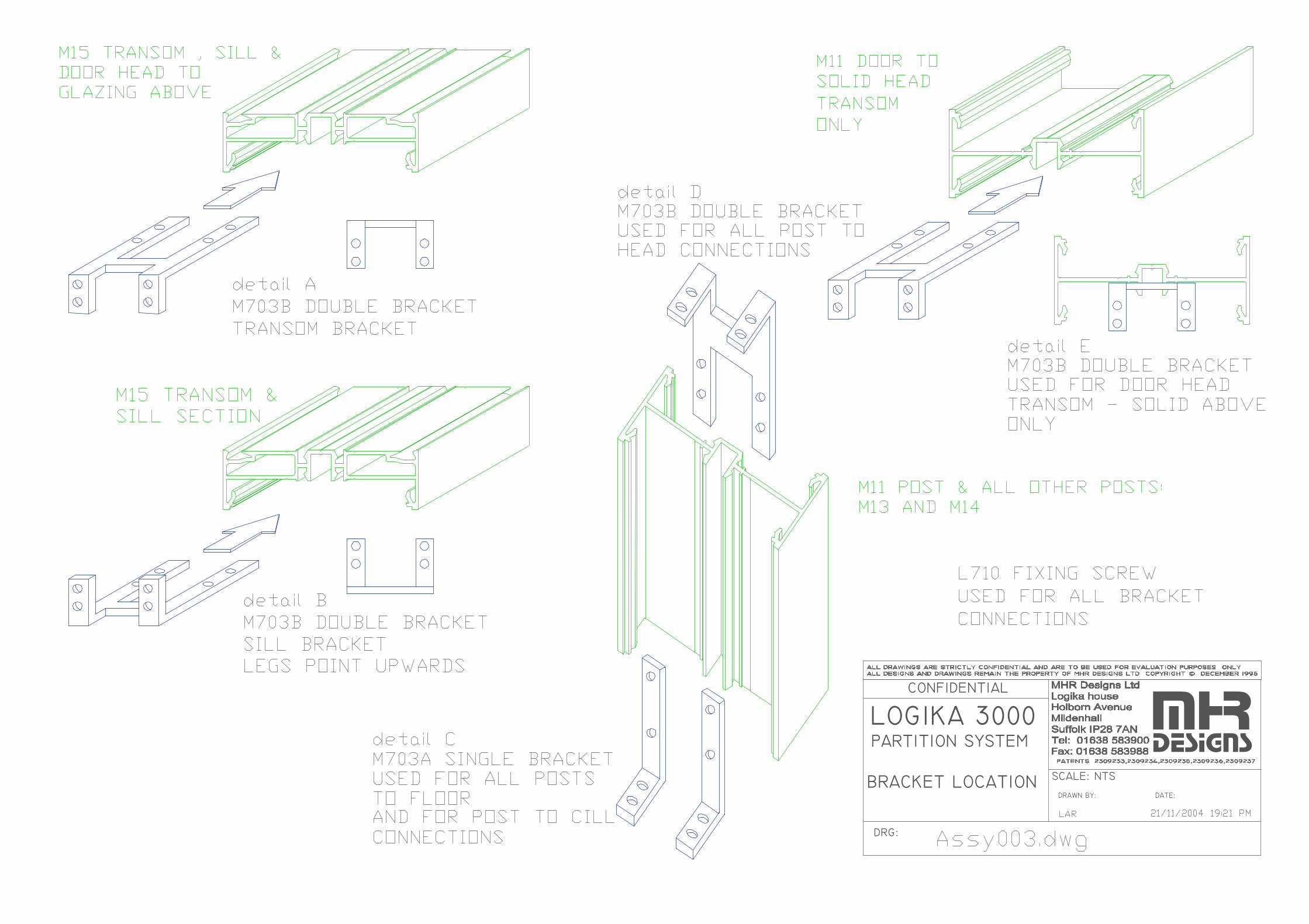
BRACKET LOCATION
LOGIKA 3000 PARTITION SYSTEM
DRG:
CONFIDENTIAL
DRAWN BY:
SCALE: NTS
DATE:
mhrdesigns
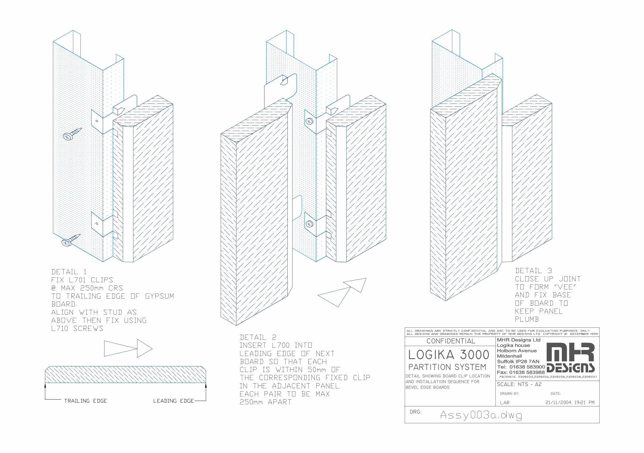
BEVEL EDGE BOARDS
DETAIL SHOWING BOARD CLIP LOCATION
LOGIKA 3000 PARTITION SYSTEM
AND INSTALLATION SEQUENCE FOR
DRG:
CONFIDENTIAL
SCALE: NTS − A2
DRAWN BY: DATE:
mhrdesigns
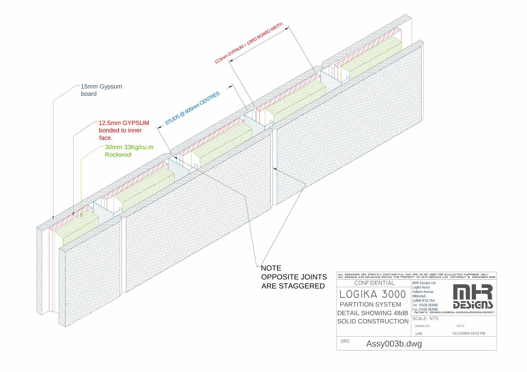
DETAIL SHOWING 48dB
LOGIKA 3000 PARTITION SYSTEM
SOLID CONSTRUCTION
DRG:
CONFIDENTIAL
SCALE: NTS
DRAWN BY: DATE:
mhrdesigns
LAR 21/11/2004 19:22 PM
Assy003b.dwg
15mm Gypsumboard
12.5mm GYPSUMbonded to innerface.
STUDS @ 600mm CENTRES
12.5mm GYPSUM = 1/3RD BOARD WIDTH
NOTEOPPOSITE JOINTSARE STAGGERED
30mm 33Kg/cu.mRockwool
MHR Designs LtdLogika houseHolborn AvenueMildenhallSuffolk IP28 7ANTel: 01638 583900Fax: 01638 583988
LOGIKA 3000 PARTITION SYSTEM
DRG:
CONFIDENTIAL
SCALE: A3 paper size NTS
DRAWN BY: DATE:
mhrdesigns
L AR, MHR 31/08/2006 19:35 PM
Assy003c.dwg
15mm Gypsumboard
12.5mm GYPSUMbonded to innerface.
STUDS @ 600mm CENTRES
12.5mm GYPSUM = 1/3RD BOARD WIDTH
NOTEOPPOSITE JOINTSARE STAGGERED
30mm 33Kg/cu.mRockwool
MHR Designs LtdLogika houseHolborn AvenueMildenhallSuffolk IP28 7ANTel: 01638 583900Fax: 01638 583988
pre-vinyled15mm GYPSUMBOARDS
"omega" covertrim with insertclamps board tostuds
Detail showing 48dB Rwsystem with Omegacover joints
DRG:
CONFIDENTIAL
DRAWN BY:
SCALE: 1:1 on A2DATE:
MHR Designs LtdLogika houseHolborn AvenueMildenhallSuffolk IP28 7ANTel: 01638 583900Fax: 01638 583988
mhrdesigns
SECTIONAL DETAILS OF SOLIDCONSTRUCTION FOR VARIOUSTESTED SOUND PERFORMANCE
26/09/2006 19:44 PMLAR
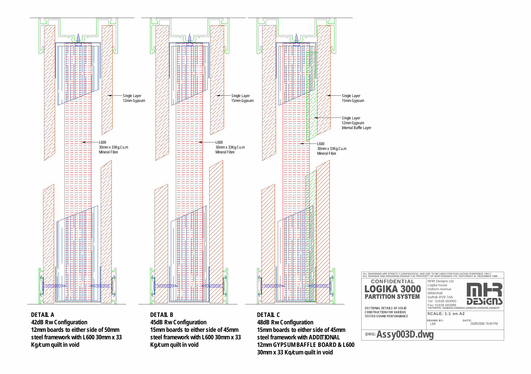
Assy003D.dwg
DETAIL A42dB Rw Configuration12mm boards to either side of 50mm steel framework with L600 30mm x 33 Kg/cum quilt in void
DETAIL B45dB Rw Configuration15mm boards to either side of 45mm steel framework with L600 30mm x 33 Kg/cum quilt in void
DETAIL C48dB Rw Configuration15mm boards to either side of 45mm steel framework with ADDITIONAL 12mm GYPSUM BAFFLE BOARD & L600 30mm x 33 Kg/cum quilt in void
L60030mm x 33Kg.Cu.mMineral Fibre
Single Layer12mm Gypsum
Single Layer15mm Gypsum
Single Layer15mm Gypsum
Single Layer12mm GypsumInternal Baffle Layer
L60030mm x 33Kg.Cu.mMineral Fibre
L60030mm x 33Kg.Cu.mMineral Fibre
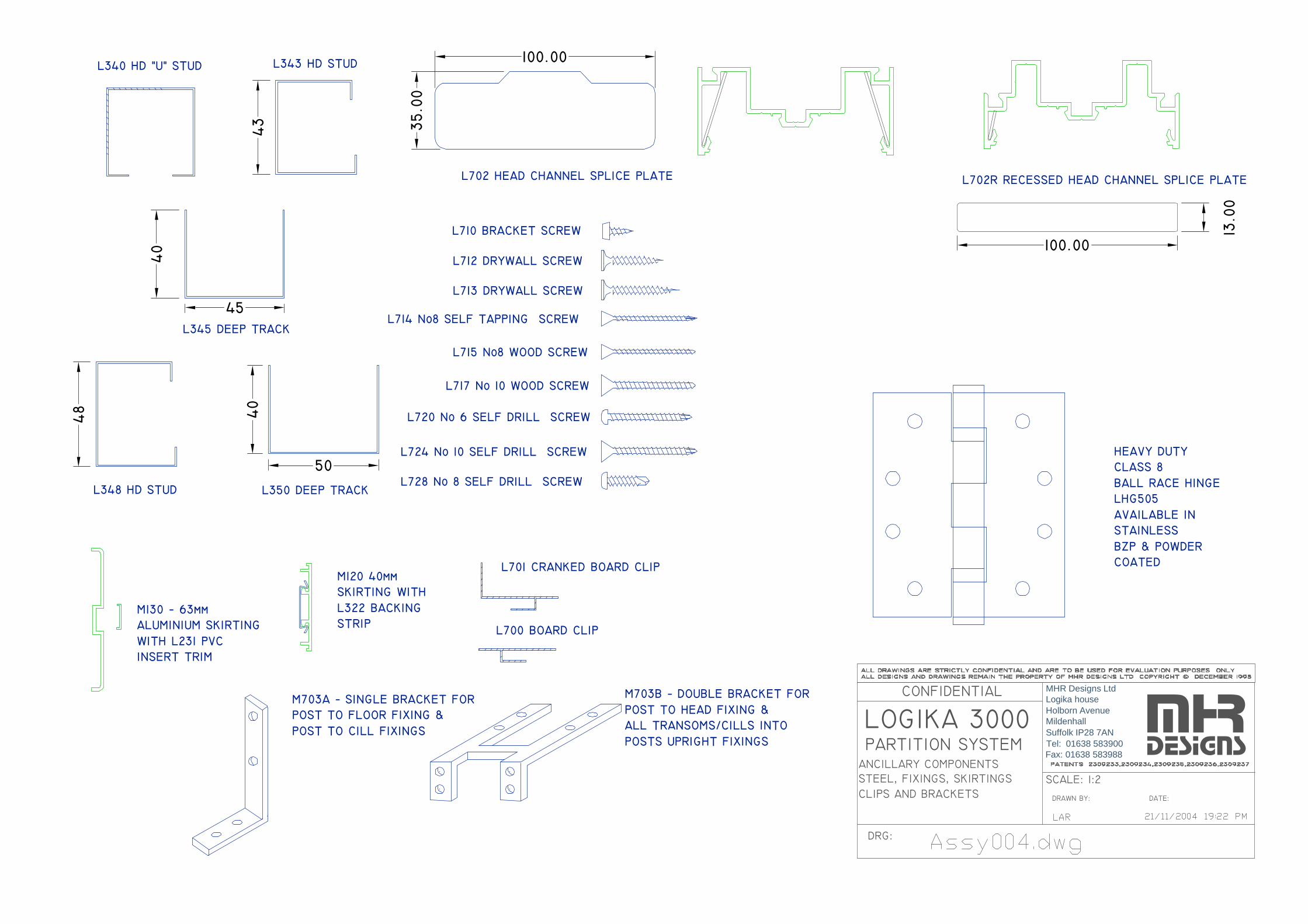
L340 HD "U" STUD L343 HD STUD
L345 DEEP TRACK
L348 HD STUD L350 DEEP TRACK
L702 HEAD CHANNEL SPLICE PLATE
L710 BRACKET SCREW
L712 DRYWALL SCREW
L713 DRYWALL SCREW
L714 No8 SELF TAPPING SCREW
L715 No8 WOOD SCREW
L717 No 10 WOOD SCREW
L724 No 10 SELF DRILL SCREW
L720 No 6 SELF DRILL SCREW
L701 CRANKED BOARD CLIP
L700 BOARD CLIP
M120 40mmSKIRTING WITHL322 BACKINGSTRIP
M130 − 63mmALUMINIUM SKIRTINGWITH L231 PVCINSERT TRIM
M703A − SINGLE BRACKET FORPOST TO FLOOR FIXING &POST TO CILL FIXINGS
M703B − DOUBLE BRACKET FORPOST TO HEAD FIXING &ALL TRANSOMS/CILLS INTOPOSTS UPRIGHT FIXINGS
HEAVY DUTYCLASS 8BALL RACE HINGELHG505AVAILABLE INSTAINLESSBZP & POWDERCOATED
L728 No 8 SELF DRILL SCREW
CLIPS AND BRACKETS
ANCILLARY COMPONENTS
LOGIKA 3000 PARTITION SYSTEM
STEEL, FIXINGS, SKIRTINGS
DRG:
CONFIDENTIAL
DRAWN BY:
SCALE: 1:2
DATE:
mhrdesigns
100.00
35.0
0
13.0
0
100.00
L702R RECESSED HEAD CHANNEL SPLICE PLATE
40
50
45
40
43
48
MHR Designs LtdLogika houseHolborn AvenueMildenhallSuffolk IP28 7ANTel: 01638 583900Fax: 01638 583988
DIMENSIONS OF INFILL INDICATIVE ONLYACTUAL SIZE TO SITE MEASUREMENTS
58.2
40.2
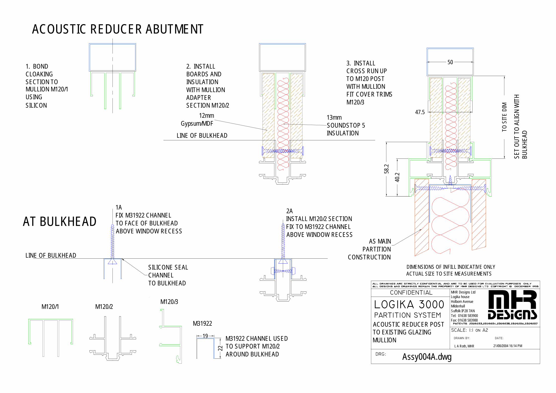
1. BONDCLOAKINGSECTION TOMULLION M120/1USINGSILICON
2. INSTALLBOARDS ANDINSULATIONWITH MULLIONADAPTERSECTION M120/2
TO S
ITE
DIM
47.5
50
M120/1 M120/2M120/3
WITH MULLION
3. INSTALL
M120/3FIT COVER TRIMS
TO M120 POSTCROSS RUN UP
M31922
19
22AT BULKHEAD
ACOUSTIC REDUCER ABUTMENT
12mmGypsum/MDF
13mmSOUNDSTOP 5INSULATION
AS MAINPARTITION
CONSTRUCTION
SILICONE SEALCHANNELTO BULKHEAD
SET
OUT
TO
ALI
GN
WIT
H BU
LKHE
AD
LINE OF BULKHEAD
LINE OF BULKHEAD
LOGIKA 3000 PARTITION SYSTEM
DRG:
CONFIDENTIAL
DRAWN BY:
SCALE: 1:1 on A2
DATE:
MHRDESIGNS
M31922 CHANNEL USEDTO SUPPORT M120/2AROUND BULKHEAD
1AFIX M31922 CHANNELTO FACE OF BULKHEADABOVE WINDOW RECESS
2AINSTALL M120/2 SECTIONFIX TO M31922 CHANNELABOVE WINDOW RECESS
ACOUSTIC REDUCER POSTTO EXISTING GLAZING MULLION
21/08/2004 16:14 PML A Roth, MHR
Assy004A.dwg
MHR Designs LtdLogika houseHolborn AvenueMildenhallSuffolk IP28 7ANTel: 01638 583900Fax: 01638 583988
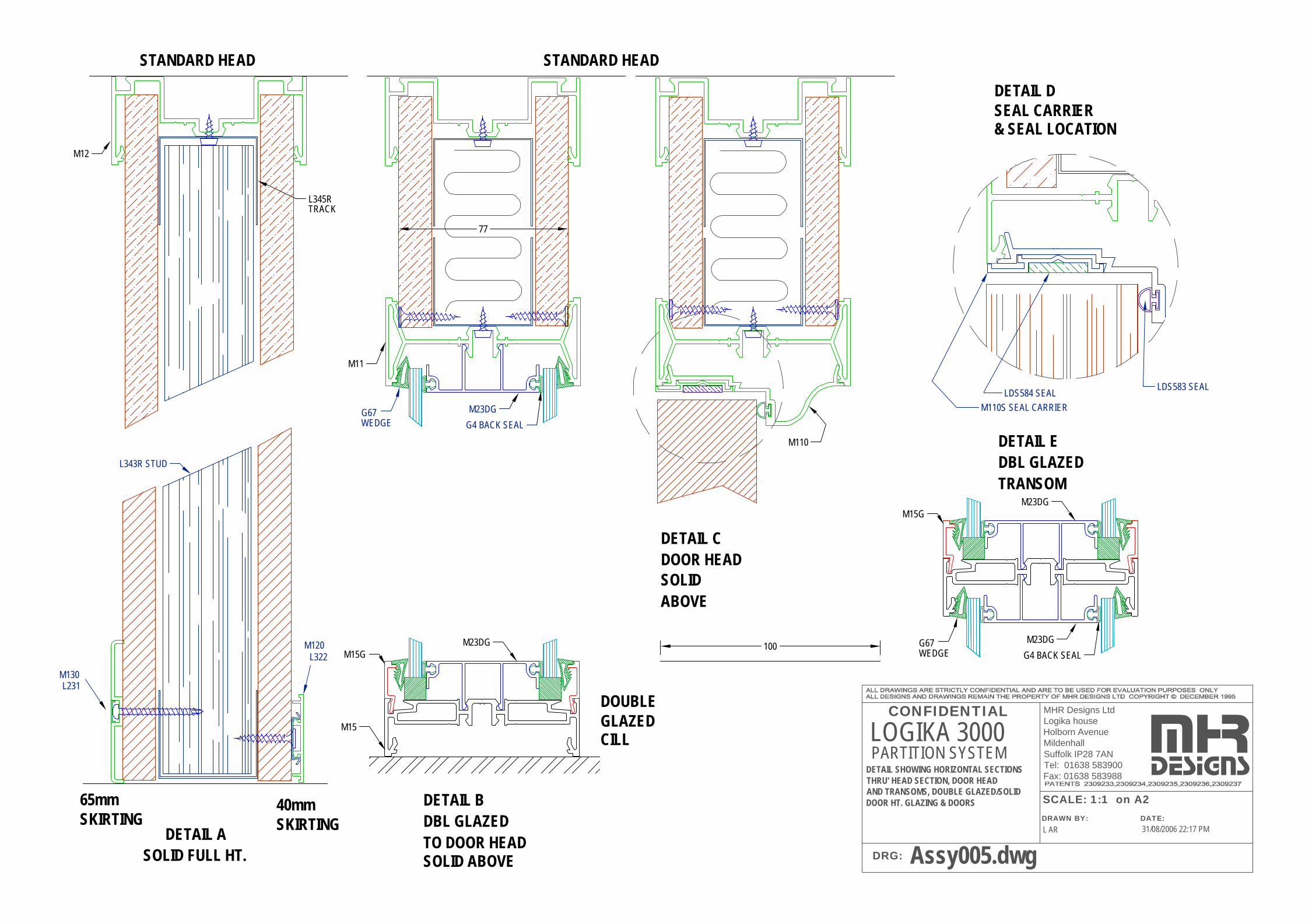
SOLID FULL HT.DETAIL A
DBL GLAZED DETAIL B
DOOR HEADDETAIL C
SKIRTING40mm
DOUBLEGLAZEDCILL
TO DOOR HEAD
SOLIDABOVE
SEAL CARRIER& SEAL LOCATION
SKIRTING65mm
DBL GLAZED DETAIL E
TRANSOM
DETAIL D
STANDARD HEAD
100
SOLID ABOVE
STANDARD HEAD
L231M130
L322M120
L343R STUD
M110S SEAL CARRIERLDS584 SEAL
LDS583 SEAL
TRACKL345R
DETAIL SHOWING HORIZONTAL SECTIONS THRU' HEAD SECTION, DOOR HEADAND TRANSOMS, DOUBLE GLAZED/SOLID DOOR HT. GLAZING & DOORS
LOGIKA 3000
31/08/2006 22:17 PML AR
Assy005.dwg
PARTITION SYSTEM
DRG:
CONFIDENTIAL
mhrMHR Designs LtdLogika houseHolborn AvenueMildenhallSuffolk IP28 7ANTel: 01638 583900Fax: 01638 583988 designsSCALE: 1:1 on A2DRAWN BY: DATE:
M12
77
G4 BACK SEAL
M23DGWEDGEG67
M11
M110
M15
M15GM23DG
M15GM23DG
G4 BACK SEAL
M23DGWEDGEG67
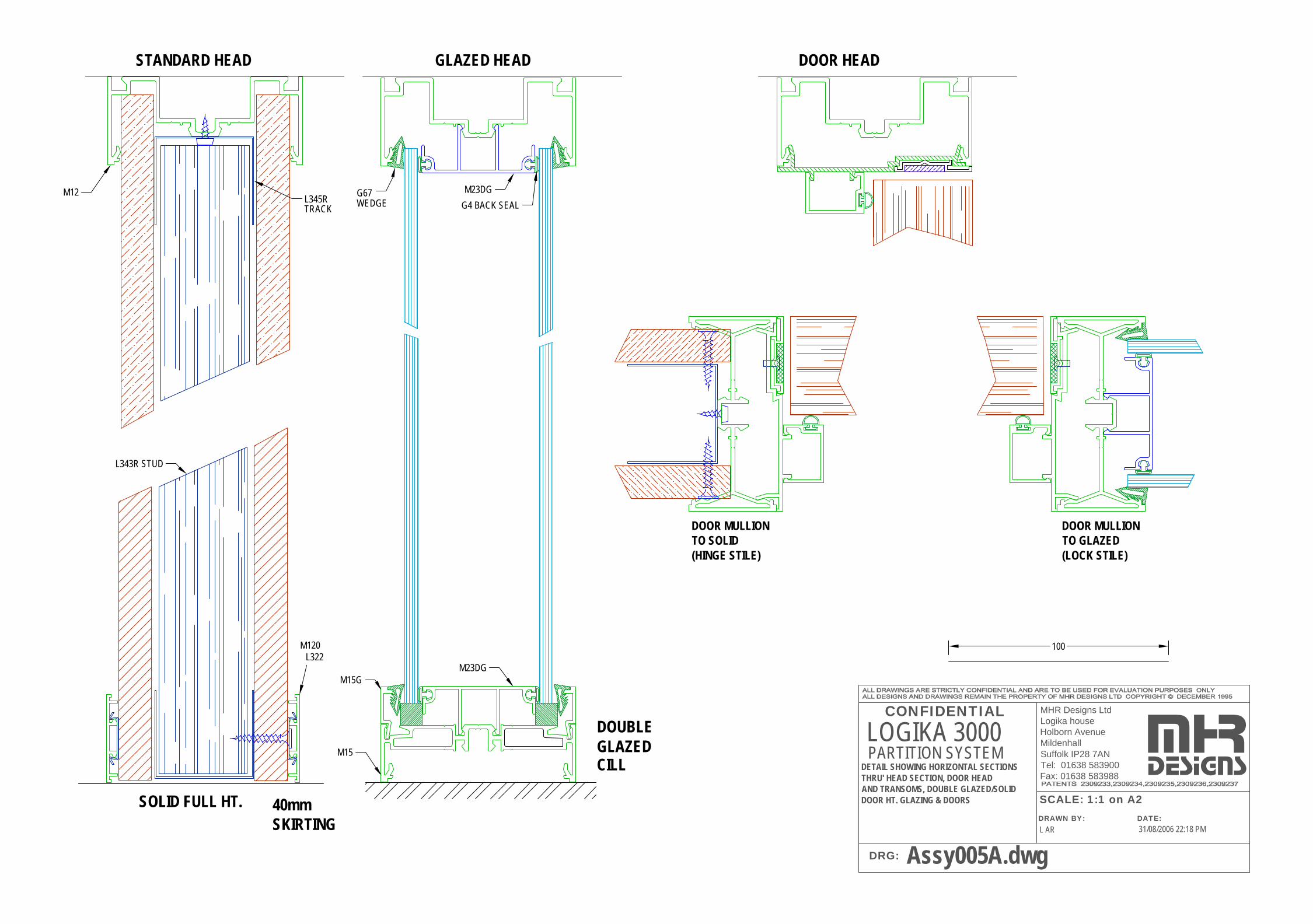
SOLID FULL HT.SKIRTING40mm
DOUBLEGLAZEDCILL
M15
L343R STUD
L322M120
GLAZED HEAD
LOGIKA 3000 PARTITION SYSTEM
DRG:
CONFIDENTIAL
DRAWN BY:
SCALE: 1:1 on A2DATE:
100
STANDARD HEAD
MHR Designs LtdLogika houseHolborn AvenueMildenhallSuffolk IP28 7ANTel: 01638 583900Fax: 01638 583988
TRACKL345R
M12
mhrdesignsDETAIL SHOWING HORIZONTAL SECTIONS
THRU' HEAD SECTION, DOOR HEADAND TRANSOMS, DOUBLE GLAZED/SOLID DOOR HT. GLAZING & DOORS
31/08/2006 22:18 PML AR
Assy005A.dwg
G4 BACK SEAL
M23DGWEDGEG67
M15GM23DG
DOOR HEAD
DOOR MULLIONTO GLAZED(LOCK STILE)
DOOR MULLIONTO SOLID(HINGE STILE)
GLAZING HEAD
LOGIKA 3000 PARTITION SYSTEM
DRG:
CONFIDENTIAL
DRAWN BY:
SCALE: 1:1 on A2
DATE:
mhrdesigns
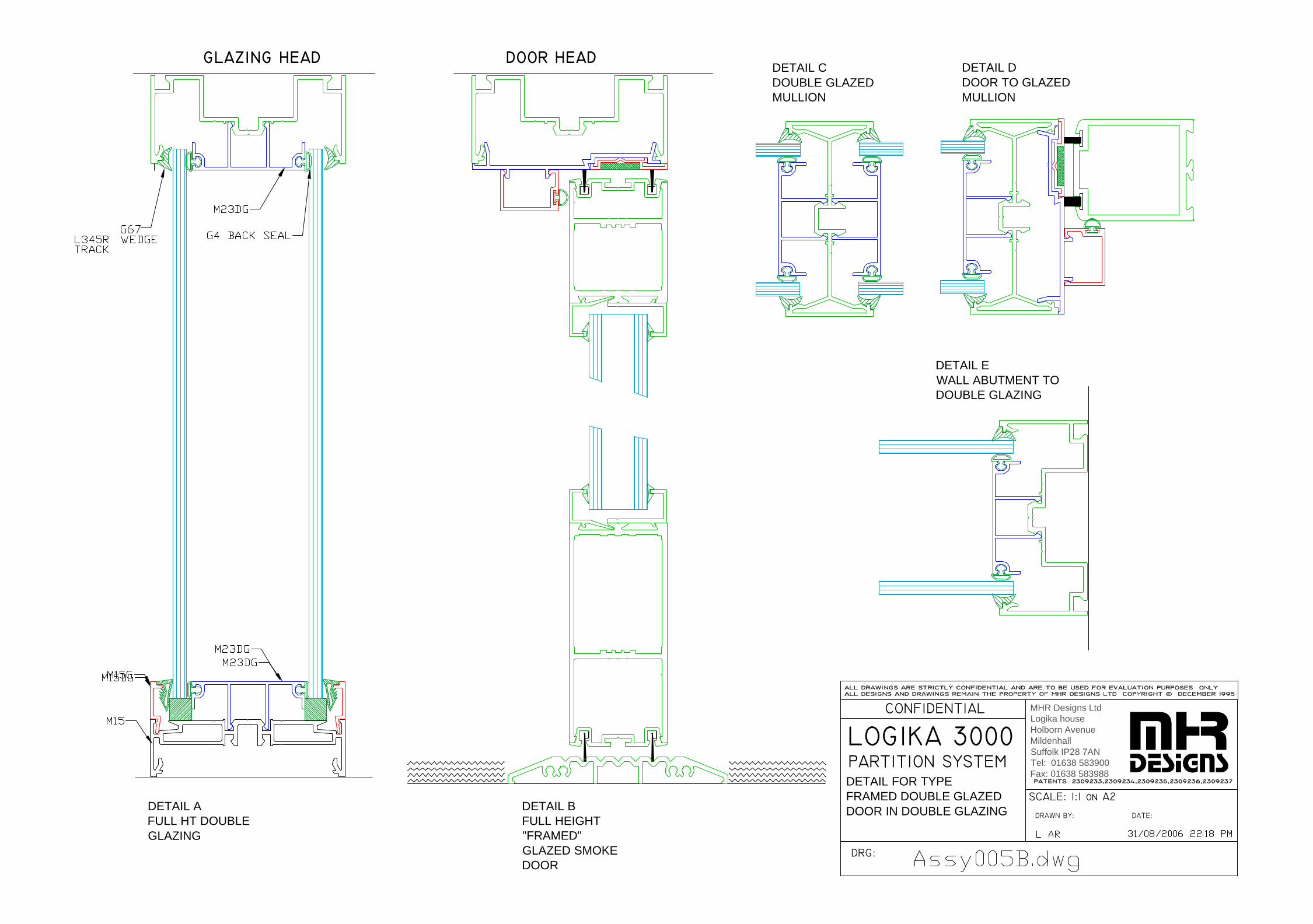
DETAIL AFULL HT DOUBLEGLAZING
DOOR HEAD
DETAIL BFULL HEIGHT"FRAMED"GLAZED SMOKEDOOR
DETAIL CDOUBLE GLAZEDMULLION
DETAIL DDOOR TO GLAZEDMULLION
DETAIL EWALL ABUTMENT TODOUBLE GLAZING
DETAIL FOR TYPEFRAMED DOUBLE GLAZED DOOR IN DOUBLE GLAZING
MHR Designs LtdLogika houseHolborn AvenueMildenhallSuffolk IP28 7ANTel: 01638 583900Fax: 01638 583988
GLAZING HEAD
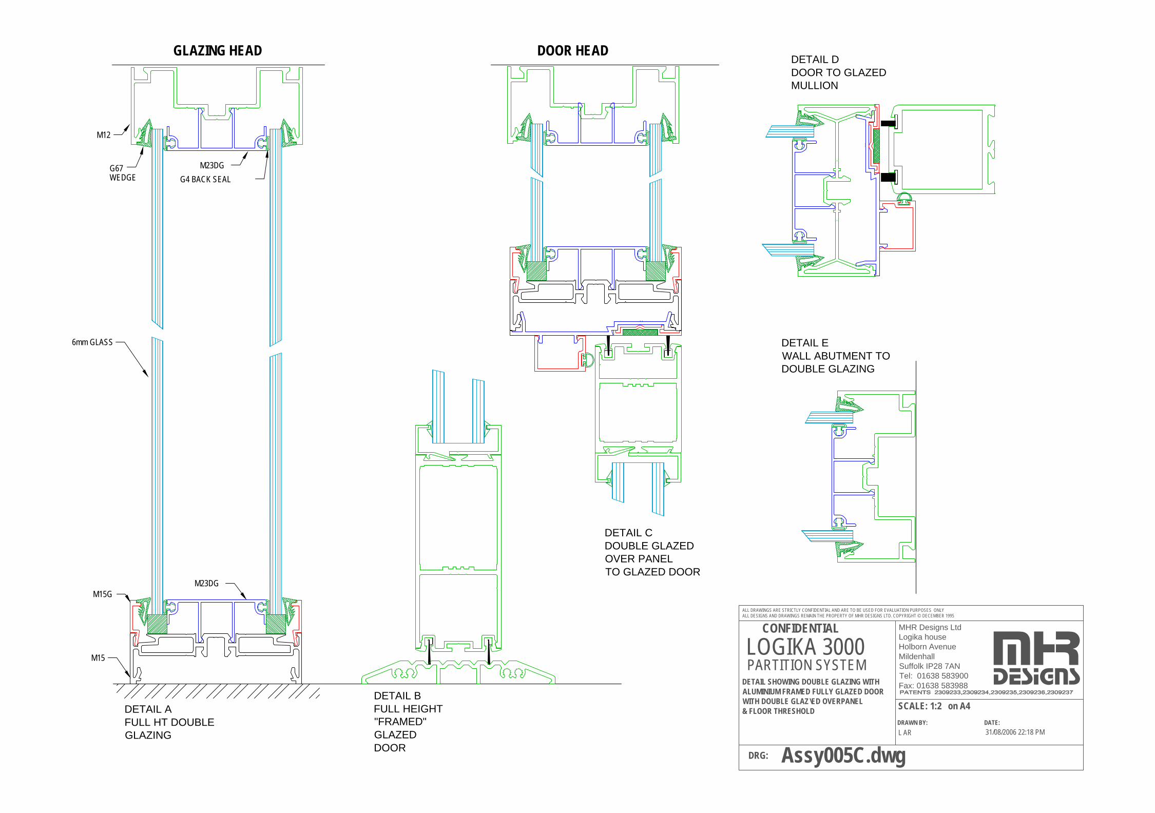
DETAIL AFULL HT DOUBLEGLAZING
DOOR HEAD
DETAIL BFULL HEIGHT"FRAMED"GLAZED DOOR
DETAIL CDOUBLE GLAZEDOVER PANELTO GLAZED DOOR
DETAIL DDOOR TO GLAZEDMULLION
DETAIL EWALL ABUTMENT TODOUBLE GLAZING
6mm GLASS
M12
M15
M15GM23DG
G4 BACK SEAL
M23DGWEDGEG67
31/08/2006 22:18 PML AR
Assy005C.dwg
MHR Designs LtdLogika houseHolborn AvenueMildenhallSuffolk IP28 7ANTel: 01638 583900Fax: 01638 583988
DRAWN BY:
SCALE: 1:2 on A4
ALL DRAWINGS ARE STRICTLY CONFIDENTIAL AND ARE TO BE USED FOR EVALUATION PURPOSES ONLYALL DESIGNS AND DRAWINGS REMAIN THE PROPERTY OF MHR DESIGNS LTD. COPYRIGHT © DECEMBER 1995
PARTITION SYSTEMLOGIKA 3000
DETAIL SHOWING DOUBLE GLAZING WITH ALUMINIUM FRAMED FULLY GLAZED DOORWITH DOUBLE GLAZ\ED OVERPANEL& FLOOR THRESHOLD
DRG:
CONFIDENTIAL
mhrdesigns
DATE:
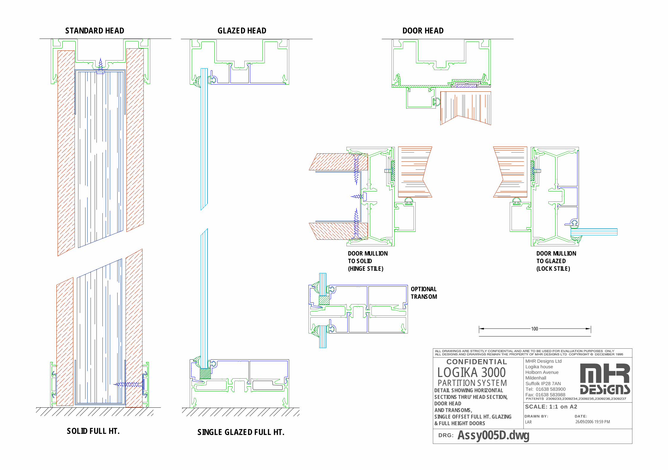
SOLID FULL HT.
GLAZED HEAD
LOGIKA 3000 PARTITION SYSTEM
DRG:
CONFIDENTIAL
DRAWN BY:
SCALE: 1:1 on A2DATE:
100
STANDARD HEAD
MHR Designs LtdLogika houseHolborn AvenueMildenhallSuffolk IP28 7ANTel: 01638 583900Fax: 01638 583988
mhrdesignsDETAIL SHOWING HORIZONTAL
SECTIONS THRU' HEAD SECTION, DOOR HEADAND TRANSOMS,SINGLE OFFSET FULL HT. GLAZING& FULL HEIGHT DOORS 26/09/2006 19:59 PMLAR
Assy005D.dwg
DOOR HEAD
DOOR MULLIONTO GLAZED(LOCK STILE)
DOOR MULLIONTO SOLID(HINGE STILE)
OPTIONALTRANSOM
SINGLE GLAZED FULL HT.
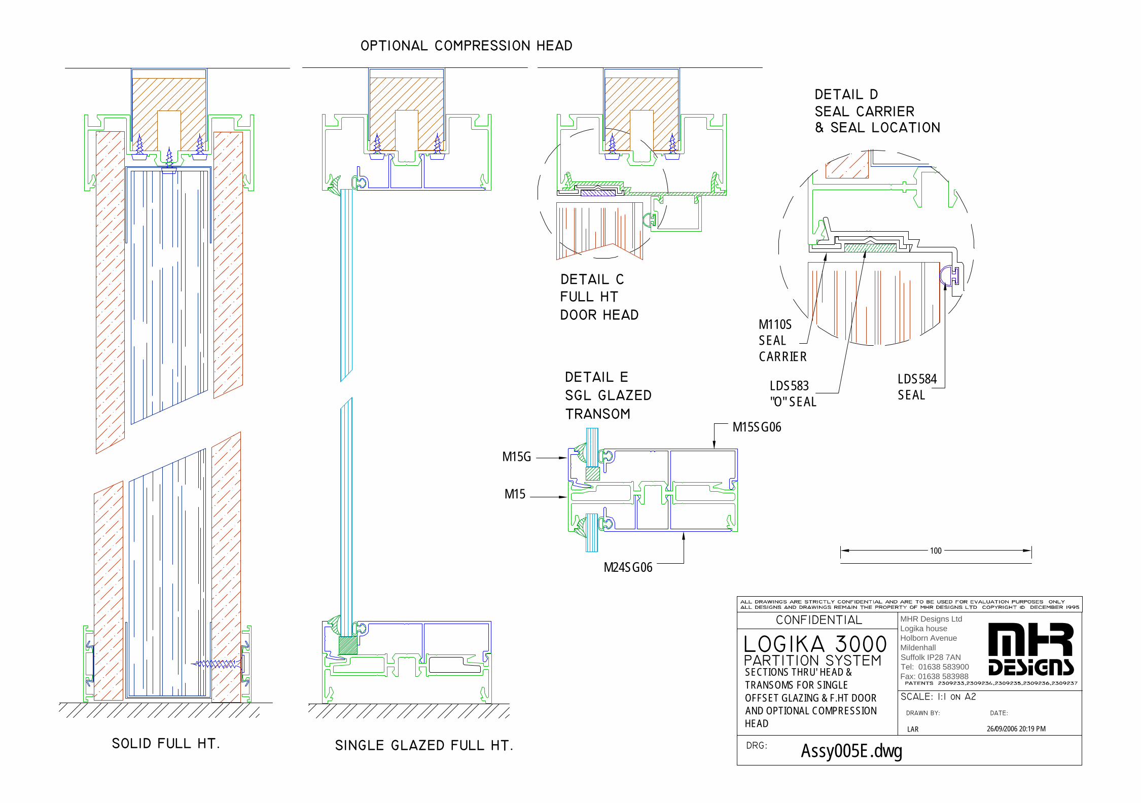
DOOR HEADFULL HT
OPTIONAL COMPRESSION HEAD
SEAL CARRIER& SEAL LOCATION
SGL GLAZED DETAIL E
TRANSOM
DETAIL D
LOGIKA 3000 PARTITION SYSTEM
DRG:
CONFIDENTIAL
DRAWN BY:
SCALE: 1:1 on A2
DATE:
DETAIL C
100
mhrdesigns
LAR 26/09/2006 20:19 PM
Assy005E.dwg
M24SG06
M15SG06
M15G
M15
MHR Designs LtdLogika houseHolborn AvenueMildenhallSuffolk IP28 7ANTel: 01638 583900Fax: 01638 583988SECTIONS THRU' HEAD &
TRANSOMS FOR SINGLE OFFSET GLAZING & F.HT DOOR AND OPTIONAL COMPRESSION HEAD
SOLID FULL HT. SINGLE GLAZED FULL HT.
M110SSEALCARRIER
LDS584SEAL
LDS583"O" SEAL
CONFIDENTIAL
LOGIKA 3000
DRAWN BY:
SCALE: 1:1 on A2
DRG:
DATE:
PARTITION SYSTEM
100
DADO TO SOLID
SINGLEGLAZED
mhrdesigns
LAR 26/09/2006 20:46 PM
Assy005F.dwg
MHR Designs LtdLogika houseHolborn AvenueMildenhallSuffolk IP28 7ANTel: 01638 583900Fax: 01638 583988SECTIONS THRU' HEAD &
TRANSOMS HALF HT SINGLE GLAZING & F.HT DOOR.
STANDARD HEAD
LDS583"O" SEAL
M110SSEALCARRIER
LDS584SEAL
M15
M15G
M24SG06
M15SG06
GLAZED HEAD DOOR HEAD
DETAIL ASOLID FULL HT.
DETAIL BSOLID TO DADOGLAZED ABOVE.
DETAIL CDOOR HEAD.
DETAIL DDOOR SEALLOCATIONS
DETAIL EOPTIONAL GLAZEDTRANSOM
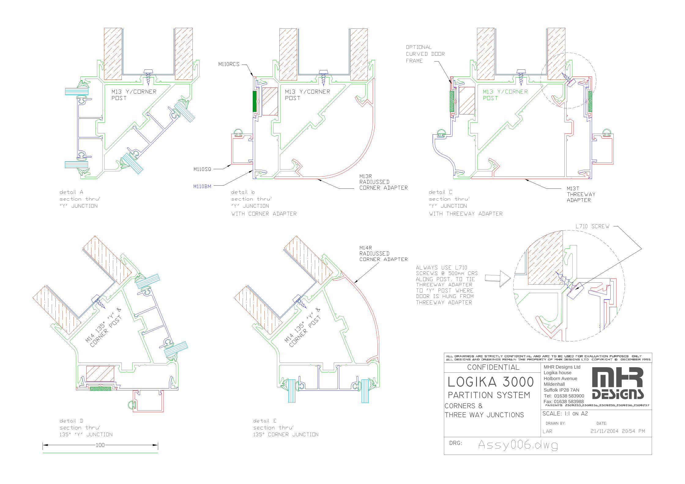
CORNERS &
LOGIKA 3000 PARTITION SYSTEM
THREE WAY JUNCTIONS
DRG:
CONFIDENTIAL
DRAWN BY:
SCALE: 1:1 on A2
DATE:
mhrdesigns
MHR Designs LtdLogika houseHolborn AvenueMildenhallSuffolk IP28 7ANTel: 01638 583900Fax: 01638 583988
LOGIKA 3000 PARTITION SYSTEM
DRG:
CONFIDENTIAL
DRAWN BY:
SCALE: 1:1 on A2
DATE:
mhrdesigns
MHR Designs LtdLogika houseHolborn AvenueMildenhallSuffolk IP28 7ANTel: 01638 583900Fax: 01638 583988
FAIR END WITHBULLNOSE INFILL
FAIR END WITHFLAT INFILL
FAIR END WITHFULL ROUND INFILL
TAPEABLE FAIR END WITHBULLNOSE INFILLONLY FOR 82mmSYSTEM WIDTH
TAPEABLE FAIR END WITHFLAT INFILLONLY FOR 82mmSYSTEM WIDTH
TAPEABLEFAIR END WITHFULL ROUND INFILLONLY FOR 82mmSYSTEM WIDTH
GLAZED FAIR END WITHBULLNOSE INFILL
GLAZED FAIR END WITHFLAT INFILL
GLA\ZED FAIR END WITHFULL ROUND INFILL
FAIR END POSTOPTIONS

DOUBLE GLAZED MULLIONS
DBL. GLAZED TO SOLID TO DBLE GLAZED
DBL. GLAZED
SINGLE GLAZED MULLIONS
TO SOLIDSGL. GLAZED
TO SGL GLAZEDSGL. GLAZED
3D SECTION THRUDETAIL E
DBLE GLAZEDMULLION
SGLE GLAZED3D SECTION THRU
MULLION
DETAIL E
DETAIL 1 DETAIL B DETAIL DDETAIL C
SINGLE and
LOGIKA 3000 PARTITION SYSTEM
MULLIONSDRG:
CONFIDENTIAL
DRAWN BY:
SCALE: 1:1 on A2
DATE:DOUBLE GLAZED
mhrdesigns
MHR Designs LtdLogika houseHolborn AvenueMildenhallSuffolk IP28 7ANTel: 01638 583900Fax: 01638 583988

DOUBLE GLAZED TRANSOMS
DBL. GLAZED TO SOLID BELOW
TRANSOMDBL. GLAZED
SINGLE GLAZED TRANSOMS
DETAIL C
DETAIL B
SINGLE and
LOGIKA 3000 PARTITION SYSTEM
TRANSOMSDRG:
CONFIDENTIAL
DRAWN BY:
SCALE: 1:1 on A2
DATE:DOUBLE GLAZED
DBL. GLAZED TO SOLID ABOVE
DETAIL A
TO SOLID BELOWSGL. GLAZED DETAIL F
DETAIL D
TRANSOMSGL. GLAZED
TO SOLID ABOVESGL. GLAZED
DETAIL GSQUARE DOOR TO SOLID ABOVE
DETAIL H
TO DBL.GLAZEDCURVED DOOR
ABOVE
mhrdesigns
DOOR HEAD TRANSOMS
MHR Designs LtdLogika houseHolborn AvenueMildenhallSuffolk IP28 7ANTel: 01638 583900Fax: 01638 583988
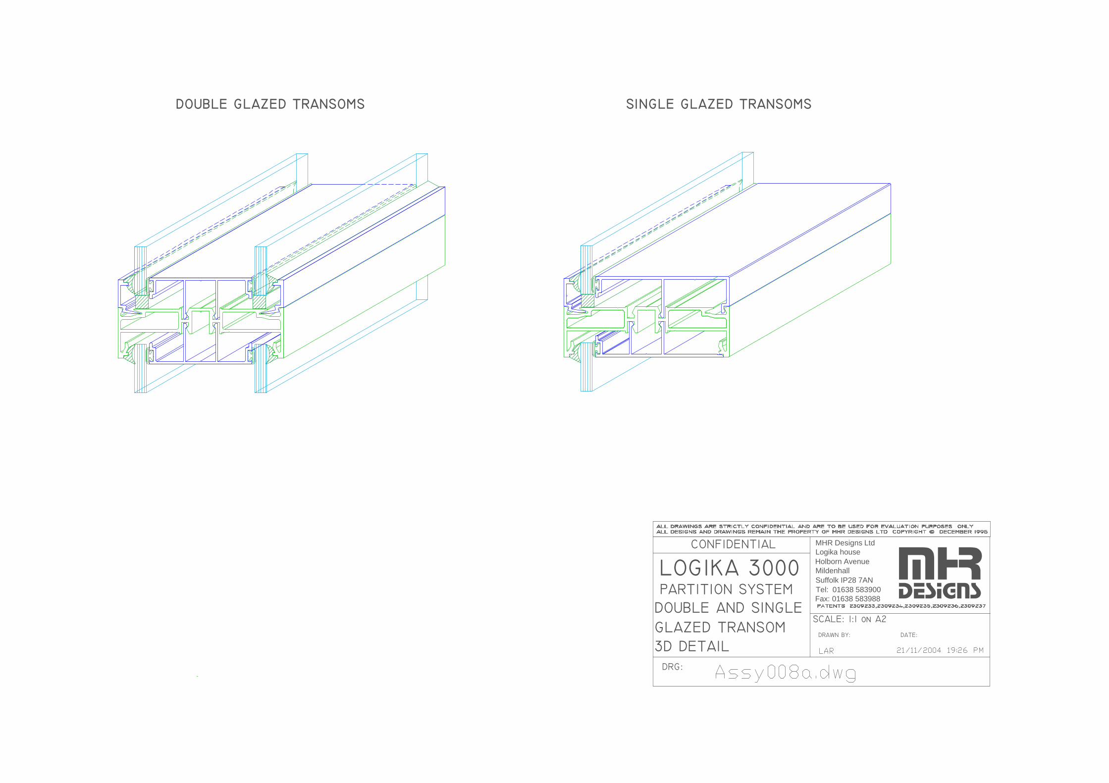
DOUBLE GLAZED TRANSOMS SINGLE GLAZED TRANSOMS
DOUBLE AND SINGLE
LOGIKA 3000 PARTITION SYSTEM
3D DETAILDRG:
CONFIDENTIAL
DRAWN BY:
SCALE: 1:1 on A2
DATE:GLAZED TRANSOM
mhrdesigns
MHR Designs LtdLogika houseHolborn AvenueMildenhallSuffolk IP28 7ANTel: 01638 583900Fax: 01638 583988
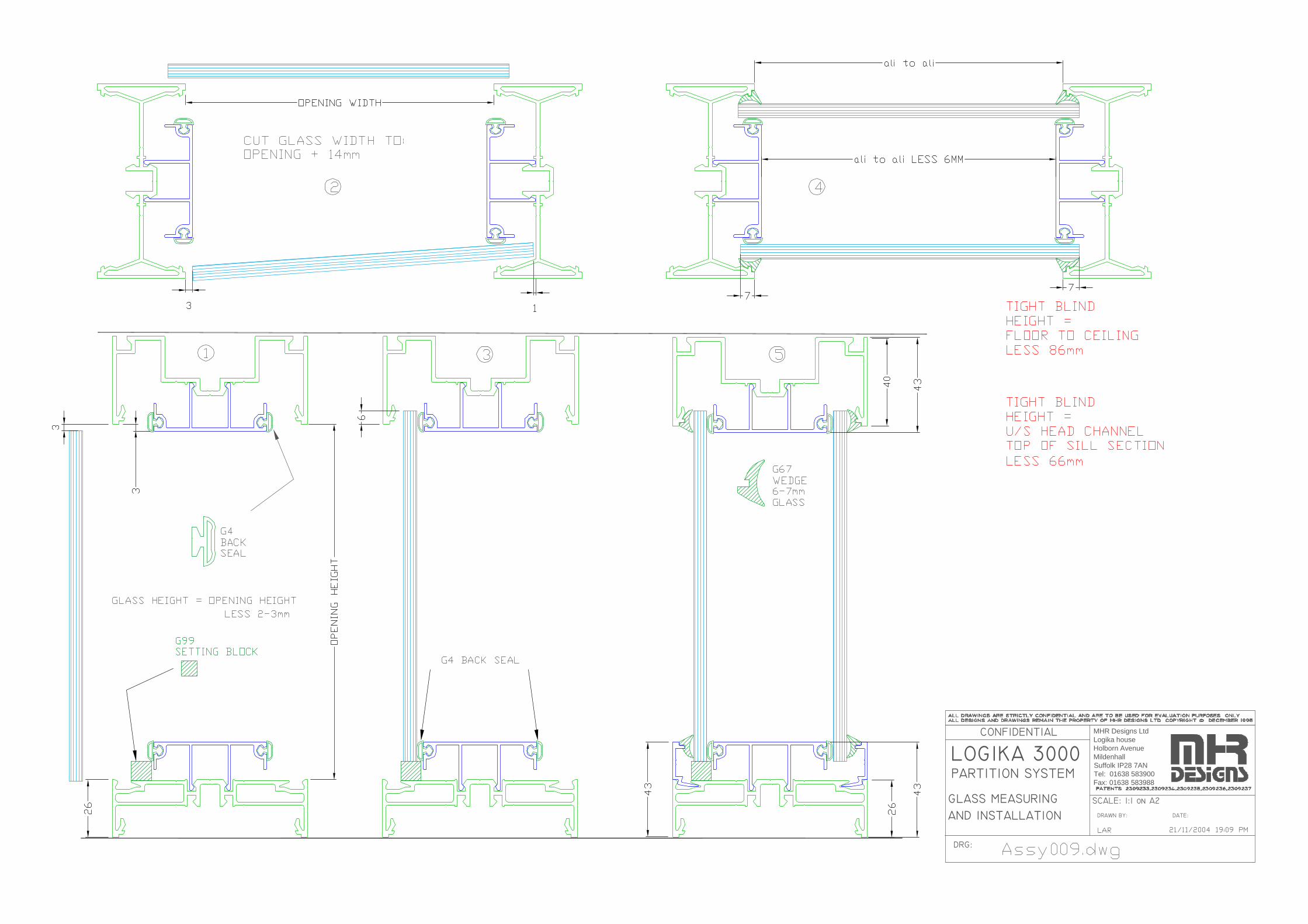
AND INSTALLATION
LOGIKA 3000 PARTITION SYSTEM
GLASS MEASURING
DRG:
CONFIDENTIAL
DRAWN BY:
SCALE: 1:1 on A2
DATE:
MHR Designs LtdLogika houseHolborn AvenueMildenhallSuffolk IP28 7ANTel: 01638 583900Fax: 01638 583988
LOGIKA 3000 PARTITION SYSTEM
DRG:
CONFIDENTIAL
DRAWN BY:
SCALE: 1:1 on A2
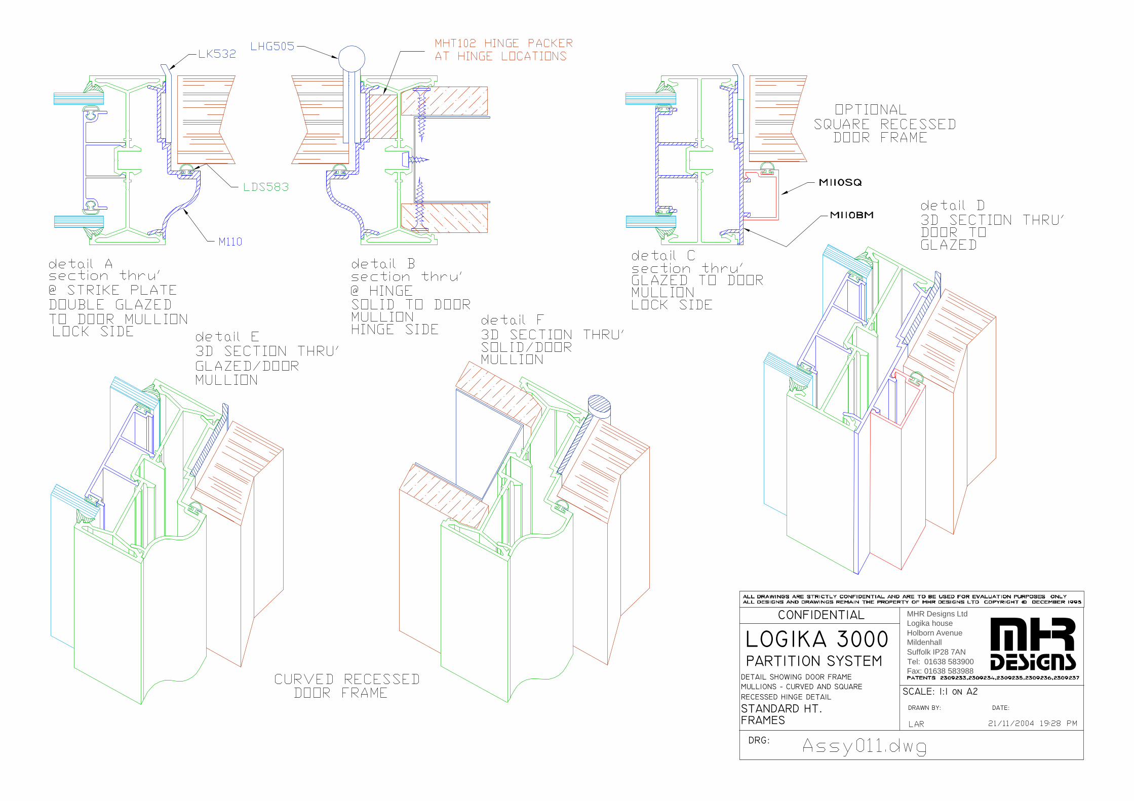
DATE:FULL HEIGHT
MULLIONS − CURVED AND SQUAREDETAIL SHOWING DOOR FRAME
RECESSED HINGE DETAIL
FRAMES
mhrdesigns
MHR Designs LtdLogika houseHolborn AvenueMildenhallSuffolk IP28 7ANTel: 01638 583900Fax: 01638 583988
LOGIKA 3000 PARTITION SYSTEM
DRG:
CONFIDENTIAL
DRAWN BY:
SCALE: 1:1 on A2
DATE:
FULL HEIGHT DOORFRAMES & HINGE POST ADDITIONAL SUPPORT
mhrdesigns
MHR Designs LtdLogika houseHolborn AvenueMildenhallSuffolk IP28 7ANTel: 01638 583900Fax: 01638 583988
LOGIKA 3000 PARTITION SYSTEM
DRG:
CONFIDENTIAL
DRAWN BY:
SCALE: 1:1 on A2
DATE:
mhrdesigns
LAR 21/11/2004 19:28 PM
Assy010c.dwg
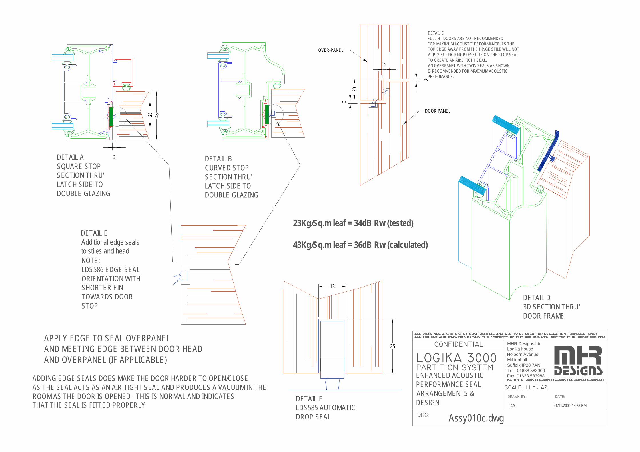
25
13
APPLY EDGE TO SEAL OVERPANELAND MEETING EDGE BETWEEN DOOR HEADAND OVERPANEL (IF APPLICABLE)
ADDING EDGE SEALS DOES MAKE THE DOOR HARDER TO OPEN/CLOSEAS THE SEAL ACTS AS AN AIR TIGHT SEAL AND PRODUCES A VACUUM IN THEROOM AS THE DOOR IS OPENED - THIS IS NORMAL AND INDICATES THAT THE SEAL IS FITTED PROPERLY
DETAIL EAdditional edge sealsto stiles and headNOTE:LDS586 EDGE SEALORIENTATION WITHSHORTER FIN TOWARDS DOOR STOP
DETAIL ASQUARE STOPSECTION THRU'LATCH SIDE TODOUBLE GLAZING
4525
DETAIL BCURVED STOPSECTION THRU'LATCH SIDE TODOUBLE GLAZING
DETAIL FLDS585 AUTOMATICDROP SEAL
DETAIL D3D SECTION THRU'DOOR FRAME
DETAIL CFULL HT DOORS ARE NOT RECOMMENDEDFOR MAXIMUM ACOUSTIC PEFORMANCE, AS THETOP EDGE AWAY FROM THE HINGE STILE WILL NOTAPPLY SUFFICIENT PRESSURE ON THE STOP SEALTO CREATE AN AIRE TIGHT SEAL.AN OVERPANEL WITH TWIN SEALS AS SHOWN IS RECOMMENDED FOR MAXIMUM ACOUSTICPERFOMANCE.
DOOR PANEL
OVER-PANEL
23Kg/Sq.m leaf = 34dB Rw (tested)
43Kg/Sq.m leaf = 36dB Rw (calculated)
ENHANCED ACOUSTIC PERFORMANCE SEALARRANGEMENTS & DESIGN
3
3
3
3
20
MHR Designs LtdLogika houseHolborn AvenueMildenhallSuffolk IP28 7ANTel: 01638 583900Fax: 01638 583988
RECESSED HINGE DETAIL
DETAIL SHOWING DOOR FRAME
LOGIKA 3000 PARTITION SYSTEM
MULLIONS − CURVED AND SQUARE
DRG:
CONFIDENTIAL
DRAWN BY:
SCALE: 1:1 on A2
DATE:
FRAMESSTANDARD HT.
mhrdesigns
MHR Designs LtdLogika houseHolborn AvenueMildenhallSuffolk IP28 7ANTel: 01638 583900Fax: 01638 583988
DRAWN BY:
SCALE: 1:1 on A2
DATE:
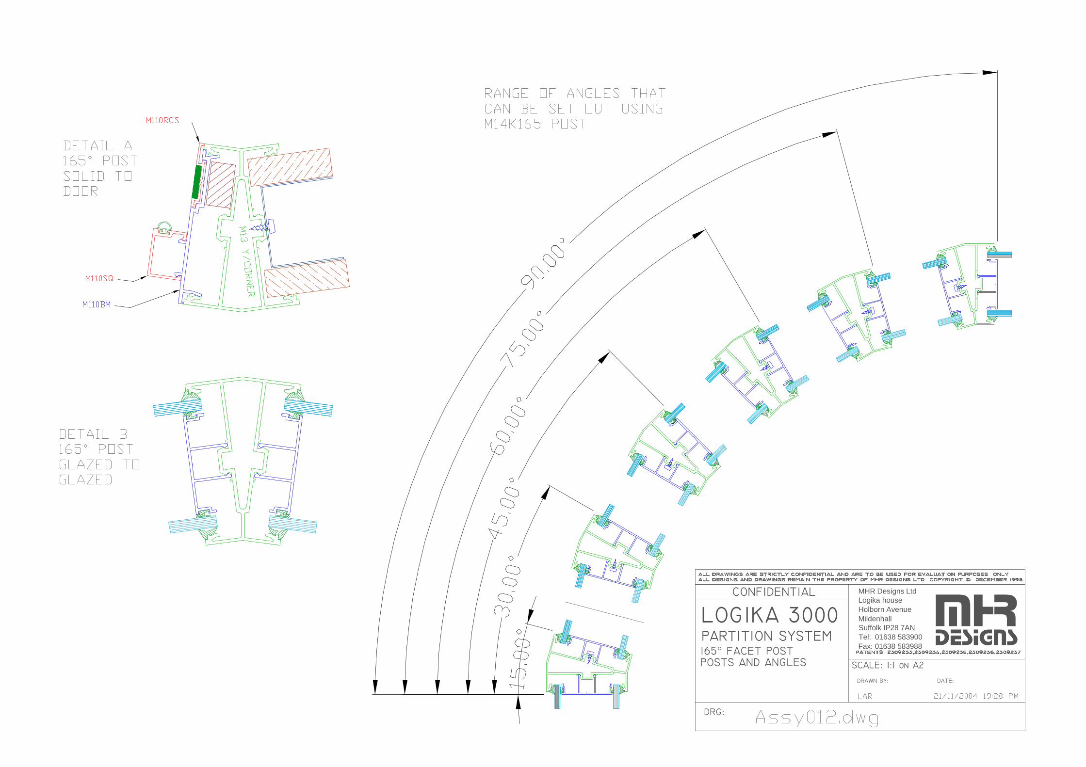
LOGIKA 3000
POSTS AND ANGLES165° FACET POSTPARTITION SYSTEM
CONFIDENTIAL
DRG:
mhrdesigns
MHR Designs LtdLogika houseHolborn AvenueMildenhallSuffolk IP28 7ANTel: 01638 583900Fax: 01638 583988
mhrdesigns
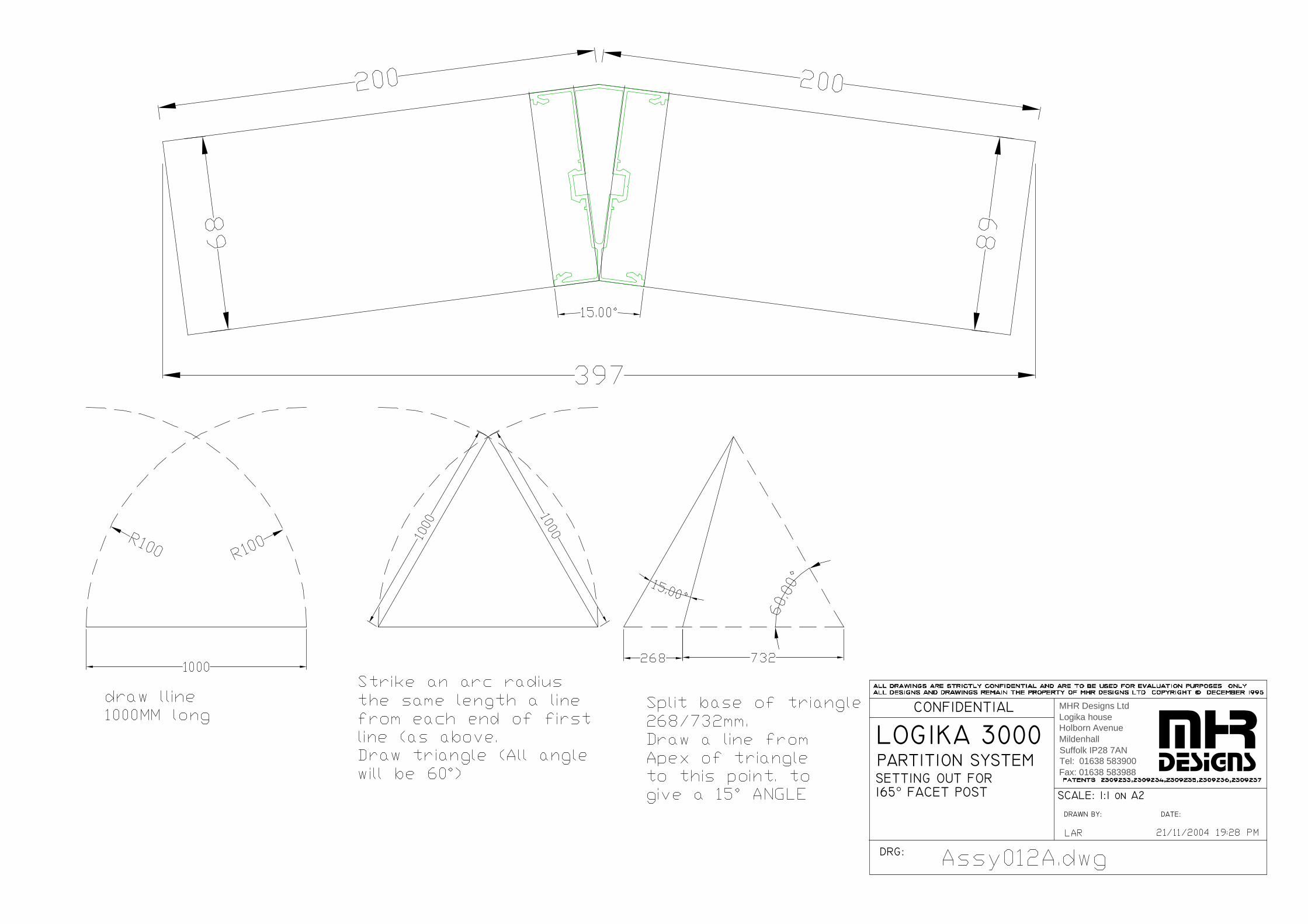
LOGIKA 3000 PARTITION SYSTEMSETTING OUT FOR165° FACET POST
DRG:
CONFIDENTIAL
DRAWN BY:
SCALE: 1:1 on A2
DATE:
MHR Designs LtdLogika houseHolborn AvenueMildenhallSuffolk IP28 7ANTel: 01638 583900Fax: 01638 583988

DOOR HEADDETAIL C
TRANSOMTO SOLID
SEAL CARRIER& SEAL LOCATION
SECTION B − DOOR TO SOLID
SECTION A − DOOR TO SOLID
LOCK POSITIONAT HINGE ANDTHRU DOOR STILES
BETWEEN HINGESTHRU’ DOOR STILES
A = DOOR WIDTH +12mm
TO HEADCHANNEL
DETAIL DDOOR HEAD
45mm DOORDIMS FOR
HINGE DIMS
FIXINGS OMITTED FOR CLARITY
AND SETTING OUT
DOOR FRAME
LOGIKA 3000 PARTITION SYSTEM
KEY DIMENSIONS
DRG:
CONFIDENTIAL
DRAWN BY:
SCALE: 1:1 on A2
DATE:
mhrdesigns
MHR Designs LtdLogika houseHolborn AvenueMildenhallSuffolk IP28 7ANTel: 01638 583900Fax: 01638 583988
Dim A - Post to Post826 door A = 838838 door A = 850900 door A = 912
LOGIKA 3000 PARTITION SYSTEM
DRG:
CONFIDENTIAL
DRAWN BY:
SCALE: 1:5 on A2
DATE:
MHR Designs LtdLogika houseHolborn AvenueMildenhallSuffolk IP28 7ANTel: 01638 583900Fax: 01638 583988
DDA REQUIRES 750mm CLEARANCE
MINIUM DOOR PANEL WIDTH = 750 + 88mm = 838mmWITH DOOR @ 3° ADJECENT WALL AS SHOWN
DDA DOORWIDTH CALCULATION
DDA REQUIRES 750mm CLEARANCE BETWEEN STOP & HANDLE
MINIUM DOOR PANEL WIDTH = 750 + 178mm = 922mmWITH DOOR @ 4° TO ADJACENT WALL AS SHOWN.
BASED ON LOCK WITH 57mm BACKSET
RECOMMENDED DOOR WIDTH TO COVER ALL DDA INSTANCESWOULD BE 925mmAs shown below door can be hung directly from corner/3 way post
838MM WIDE DOOR ONLY DDA COMPLIANT IN NON-CORNER/NON-3 WAY LOCATIONSOR WITH A 130mm NIB TO DOOR FRAME AT CORNERS & 3 WAY POSTS.
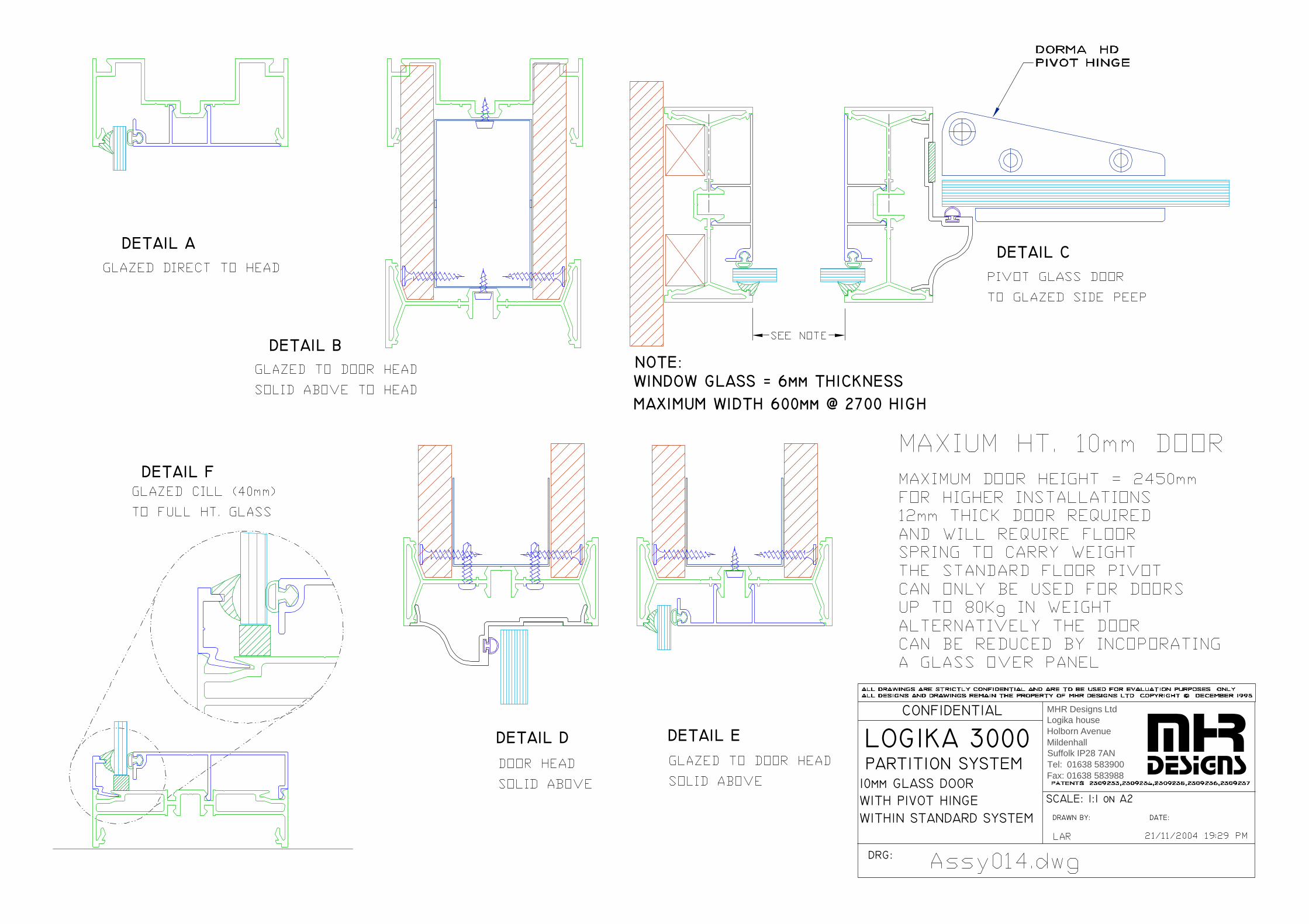
DETAIL A
DETAIL B
DETAIL C
DETAIL D DETAIL E
DETAIL F
NOTE:WINDOW GLASS = 6mm THICKNESSMAXIMUM WIDTH 600mm @ 2700 HIGH
WITHIN STANDARD SYSTEM
10mm GLASS DOOR
LOGIKA 3000 PARTITION SYSTEM
WITH PIVOT HINGE
DRG:
CONFIDENTIAL
DRAWN BY:
SCALE: 1:1 on A2
DATE:
mhrdesigns
MHR Designs LtdLogika houseHolborn AvenueMildenhallSuffolk IP28 7ANTel: 01638 583900Fax: 01638 583988

KEY DIMENSIONS
10mm PIVOT HINGED
LOGIKA 3000 PARTITION SYSTEM
GLASS DOOR
DRG:
CONFIDENTIAL
DRAWN BY:
SCALE: 1:1 on A2
DATE:
& SETTING OUT
mhrdesigns
MHR Designs LtdLogika houseHolborn AvenueMildenhallSuffolk IP28 7ANTel: 01638 583900Fax: 01638 583988
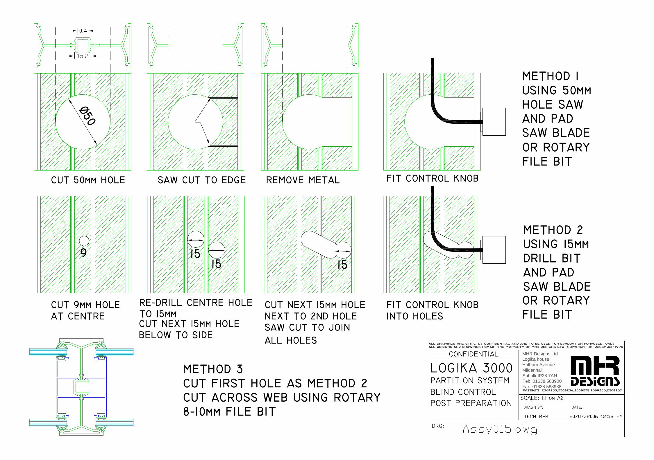
BLIND CONTROL
LOGIKA 3000 PARTITION SYSTEM
POST PREPARATION
DRG:
CONFIDENTIAL
DRAWN BY:
SCALE: 1:1 on A2
DATE:
mhrdesigns
Ø50
1515 15
METHOD 1USING 50mmHOLE SAWAND PADSAW BLADE
USING 15mm
SAW BLADEAND PADDRILL BIT
METHOD 2
CUT 9mm HOLEAT CENTRE
BELOW TO SIDECUT NEXT 15mm HOLE
CUT NEXT 15mm HOLENEXT TO 2ND HOLESAW CUT TO JOINALL HOLES
FIT CONTROL KNOBINTO HOLES
CUT 50mm HOLE SAW CUT TO EDGE REMOVE METAL FIT CONTROL KNOB
METHOD 3CUT FIRST HOLE AS METHOD 2CUT ACROSS WEB USING ROTARY8−10mm FILE BIT
FILE BITOR ROTARY
FILE BITOR ROTARYRE−DRILL CENTRE HOLE
TO 15mm
9
MHR Designs LtdLogika houseHolborn AvenueMildenhallSuffolk IP28 7ANTel: 01638 583900Fax: 01638 583988

SECTION THRU HEAD SHOWINGDETAIL d
RETAININGGLAND
TO HEADCHANNEL
DETAIL CDOOR HEAD
SECTION a − DOOR TO DOUBLE GLAZEDTHRU’ DOOR STILESABOVE LOCK BOX
SECTION b − DOOR TO SINGLE GLAZEDTHRU’ DOOR STILESABOVE LOCK BOX
DETAILS SHOWINGPOSITIONING OF 22mm O/DFLEXIBLE CONDUIT
CONDUIT LOCATION
LOGIKA 3000 PARTITION SYSTEM
ADJACENT TO DOORS
DRG:
CONFIDENTIAL
DRAWN BY:
SCALE: 1:1 on A2
DATE:
mhrdesigns
MHR Designs LtdLogika houseHolborn AvenueMildenhallSuffolk IP28 7ANTel: 01638 583900Fax: 01638 583988
SEE ASSY016A - A16E FOR DETAILS USING"KOPEX" MINI CONDUIT

LOGIKA 3000 PARTITION SYSTEM
DRG:
CONFIDENTIAL
SUFFOLK CB9 7YH
DRAWN BY:
FAX: 01440 710801TEL: 01440 710800
SCALE: 1:2
DATE:
MHR DESIGNS LTDBOUNDARY ROADHAVERHILL mhr
designs
1. Clip switch into switch plate and Fit drop wires to switch terminals using shielded spade connectors
2. Fit 222K142-3-0Heat shrink Shroud
3. Feed into 16mm Kopexmini conduit and apply heatto seal shroud to Kopex
4. Prepare post or use pre-prepared post fromMHR
5. Feed assembly in to postand fix switch plate
Fitting instructionsfor conduit fed Rocker-switch
SWITCH POST WITH KopexCONDUIT FEED TOROCKER-SWITCH
Gypsum may requirenotching in region ofswitch shroud
6 . Location OPTIONS of Kopex within post to feed up to headNOTE- LOCK SIDE OF DOOR SHOWN

LOGIKA 3000 PARTITION SYSTEM
DRG:
CONFIDENTIAL
SUFFOLK CB9 7YH
DRAWN BY:
FAX: 01440 710801TEL: 01440 710800
SCALE: 1:2
DATE:
MHR DESIGNS LTDBOUNDARY ROADHAVERHILL mhr
designs
1. Clip switch into switch plate and Fit drop wires to switch terminals using shielded spade connectors
2. Fit 222K142-3-0Heat shrink Shroud
3. Feed into 16mm Kopexmini conduit and apply heatto seal shroud to SWITCH and wires 4. Prepare post or use
pre-prepared post fromMHR
5. Feed assembly in to postand fix switch plate
Fitting instructionsfor WIRE ONLY fed Rocker-switch
SWITCH POST WITHWIRE ONLY FEED TOROCKER-SWITCH
NOTE:location of shroud loop
6 . Location OPTIONS of Kopex within post to feed up to headNOTE- LOCK SIDE OF DOOR SHOWN
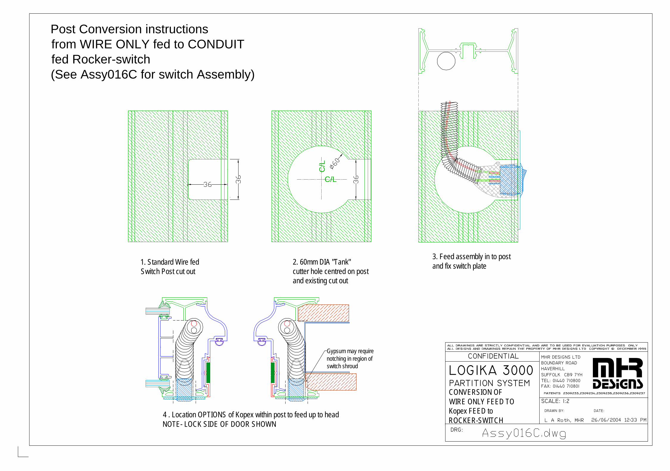
LOGIKA 3000 PARTITION SYSTEM
DRG:
CONFIDENTIAL
SUFFOLK CB9 7YH
DRAWN BY:
FAX: 01440 710801TEL: 01440 710800
SCALE: 1:2
DATE:
MHR DESIGNS LTDBOUNDARY ROADHAVERHILL mhr
designs
1. Standard Wire fedSwitch Post cut out
3. Feed assembly in to postand fix switch plate
Post Conversion instructionsfrom WIRE ONLY fed to CONDUIT fed Rocker-switch(See Assy016C for switch Assembly)
CONVERSION OF WIRE ONLY FEED TOKopex FEED to ROCKER-SWITCH
C/L
C/L
2. 60mm DIA "Tank"cutter hole centred on postand existing cut out
Gypsum may requirenotching in region ofswitch shroud
4 . Location OPTIONS of Kopex within post to feed up to headNOTE- LOCK SIDE OF DOOR SHOWN
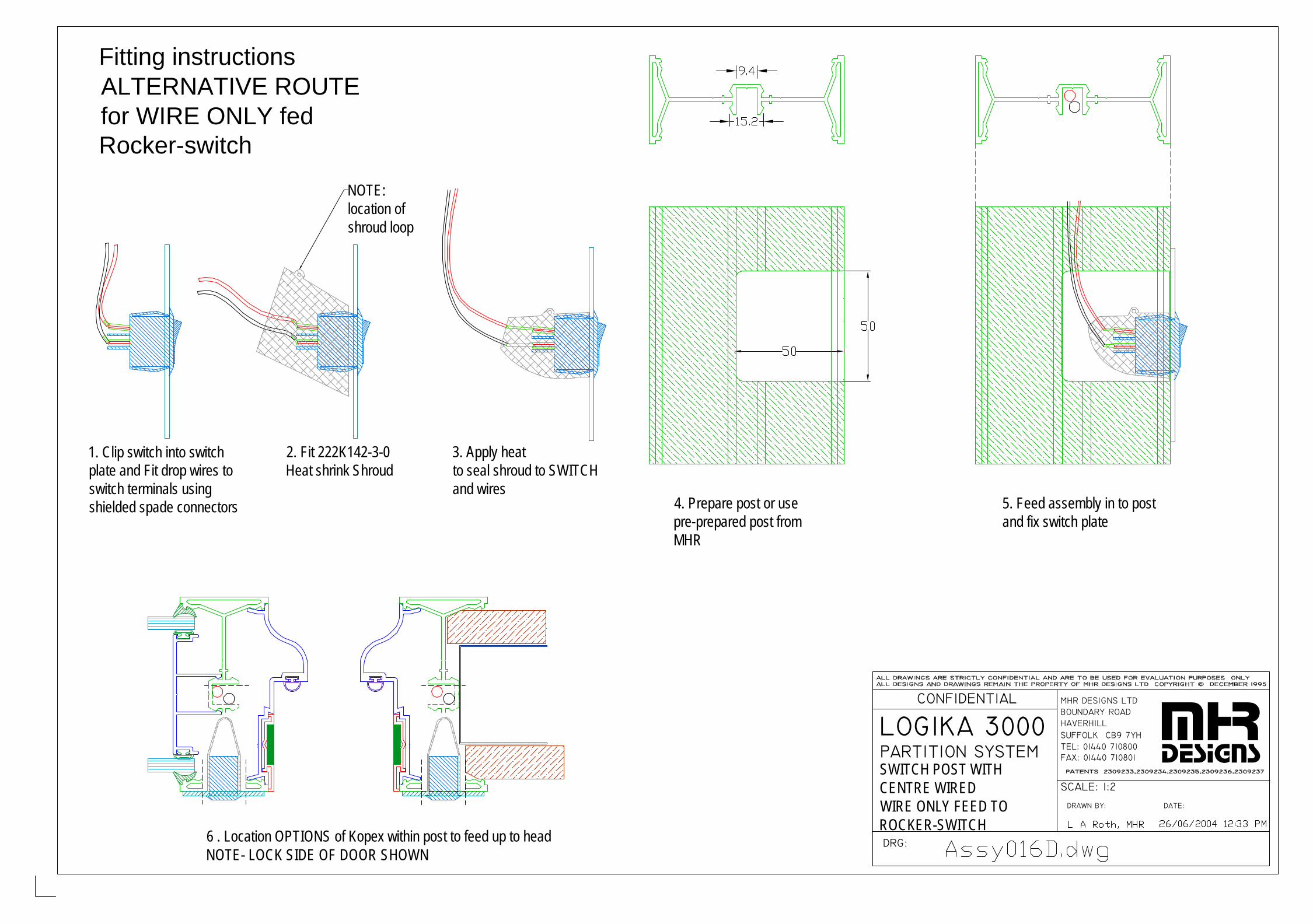
LOGIKA 3000 PARTITION SYSTEM
DRG:
CONFIDENTIAL
SUFFOLK CB9 7YH
DRAWN BY:
FAX: 01440 710801TEL: 01440 710800
SCALE: 1:2
DATE:
MHR DESIGNS LTDBOUNDARY ROADHAVERHILL mhr
designs
1. Clip switch into switch plate and Fit drop wires to switch terminals using shielded spade connectors
2. Fit 222K142-3-0Heat shrink Shroud
3. Apply heatto seal shroud to SWITCH and wires
4. Prepare post or use pre-prepared post fromMHR
5. Feed assembly in to postand fix switch plate
Fitting instructionsALTERNATIVE ROUTEfor WIRE ONLY fed Rocker-switch
SWITCH POST WITHCENTRE WIREDWIRE ONLY FEED TOROCKER-SWITCH
NOTE:location of shroud loop
6 . Location OPTIONS of Kopex within post to feed up to headNOTE- LOCK SIDE OF DOOR SHOWN

LOGIKA 3000 PARTITION SYSTEM
DRG:
CONFIDENTIAL
SUFFOLK CB9 7YH
DRAWN BY:
FAX: 01440 710801TEL: 01440 710800
SCALE: 1:2
DATE:
MHR DESIGNS LTDBOUNDARY ROADHAVERHILL mhr
designs
1. Clip switch into switch plate and Fit drop wires to switch terminals using shielded spade connectors
2. Fit 222K142-3-0Heat shrink Shroud
3. Apply heatto seal shroud to SWITCH and wires
4. Prepare post or use pre-prepared post fromMHR
5. Feed assembly in to postand fix switch plate
Fitting instructionsALTERNATIVE ROUTEfor WIRE ONLY fed Rocker-switch
SWITCH POST WITHCENTRE WIREDWIRE ONLY FEED TOTWIN ROCKER-SWITCHES
NOTE:location of shroud loop
6 . Location OPTIONS of Kopex within post to feed up to headNOTE- LOCK SIDE OF DOOR SHOWN
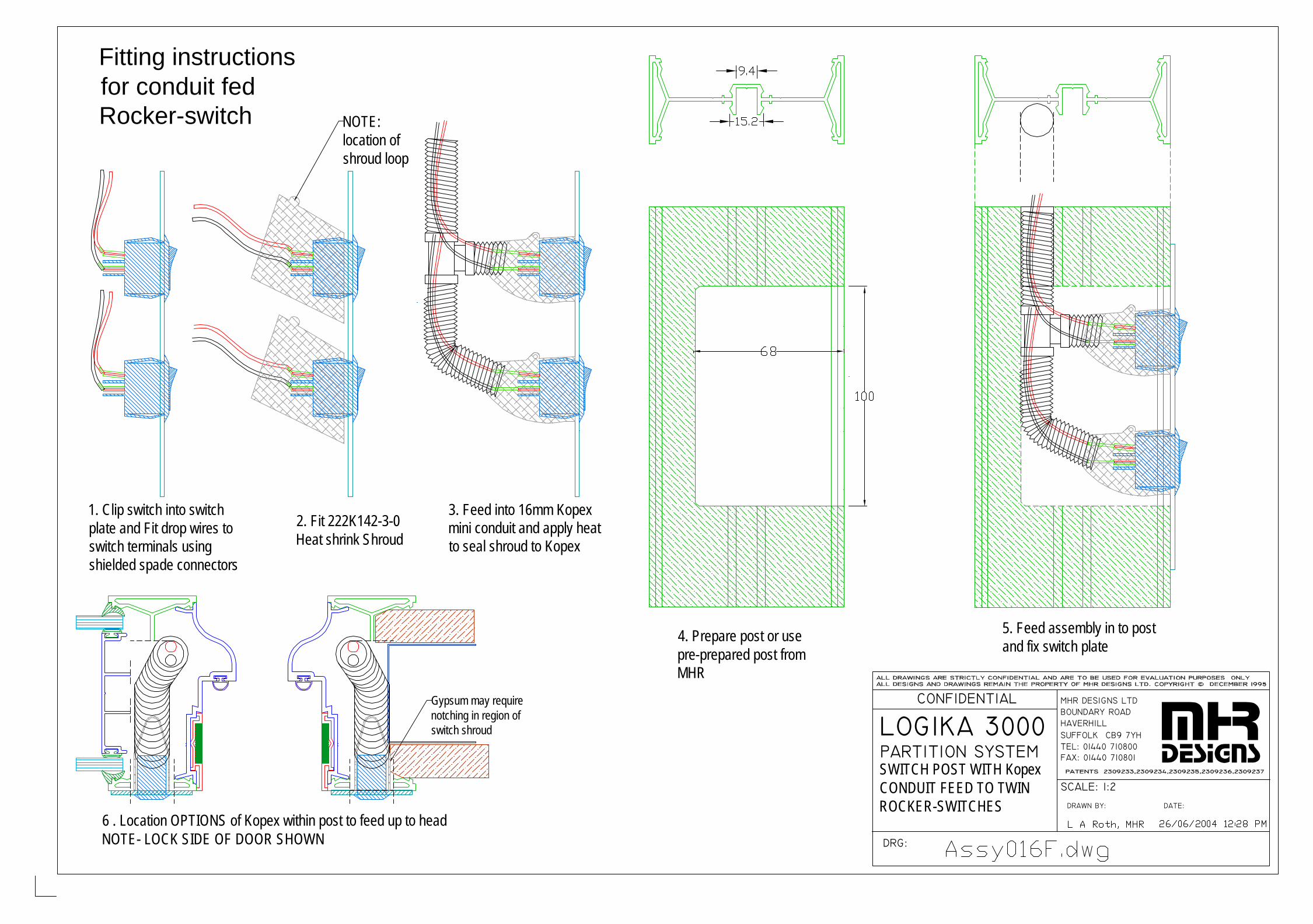
LOGIKA 3000 PARTITION SYSTEM
DRG:
CONFIDENTIAL
SUFFOLK CB9 7YH
DRAWN BY:
FAX: 01440 710801TEL: 01440 710800
SCALE: 1:2
DATE:
MHR DESIGNS LTDBOUNDARY ROADHAVERHILL mhr
designs
1. Clip switch into switch plate and Fit drop wires to switch terminals using shielded spade connectors
2. Fit 222K142-3-0Heat shrink Shroud
3. Feed into 16mm Kopexmini conduit and apply heatto seal shroud to Kopex
4. Prepare post or use pre-prepared post fromMHR
5. Feed assembly in to postand fix switch plate
Fitting instructionsfor conduit fed Rocker-switch
SWITCH POST WITH KopexCONDUIT FEED TO TWINROCKER-SWITCHES
Gypsum may requirenotching in region ofswitch shroud
6 . Location OPTIONS of Kopex within post to feed up to headNOTE- LOCK SIDE OF DOOR SHOWN
NOTE:location of shroud loop

DOOR HEADDETAIL C
TRANSOMTO SOLID
CONSTRUCTION
FIRE RATED
LOGIKA 3000 PARTITION SYSTEM
DOOR FRAME
DRG:
CONFIDENTIAL
DRAWN BY:
SCALE: 1:1 on A2
DATE:
mhrdesigns
MHR Designs LtdLogika houseHolborn AvenueMildenhallSuffolk IP28 7ANTel: 01638 583900Fax: 01638 583988
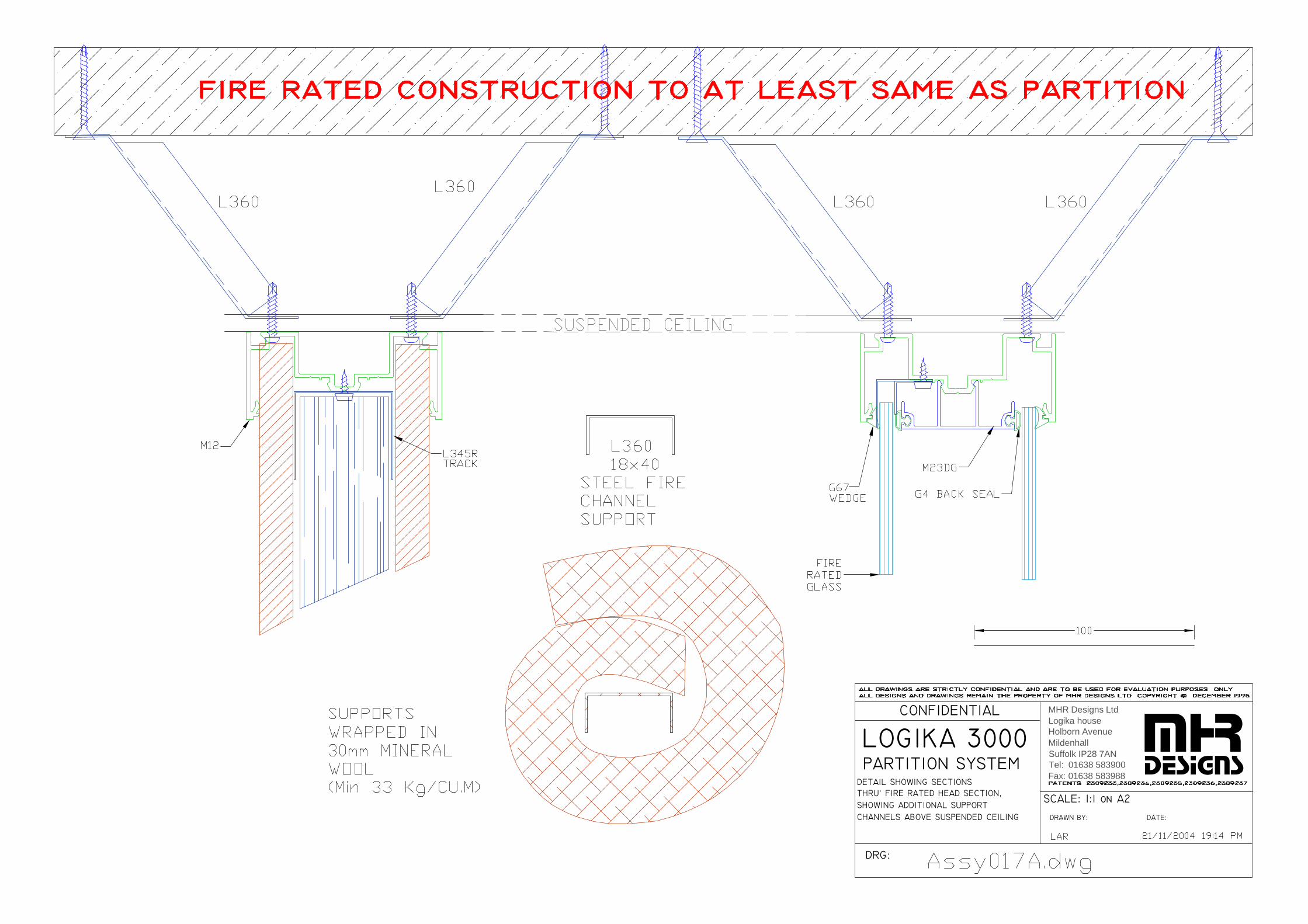
SHOWING ADDITIONAL SUPPORT
DETAIL SHOWING SECTIONS
LOGIKA 3000 PARTITION SYSTEM
THRU’ FIRE RATED HEAD SECTION,
DRG:
CONFIDENTIAL
DRAWN BY:
SCALE: 1:1 on A2
DATE:CHANNELS ABOVE SUSPENDED CEILING
mhrdesigns
MHR Designs LtdLogika houseHolborn AvenueMildenhallSuffolk IP28 7ANTel: 01638 583900Fax: 01638 583988

DOOR HEADDETAIL C
CONSTRUCTION
FIRE RATED
LOGIKA 3000 PARTITION SYSTEM
DOOR FRAME
DRG:
CONFIDENTIAL
DRAWN BY:
SCALE: 1:1 on A2
DATE:
mhrdesigns
DOOR HEADDETAIL D
TO DBLE GLAZING
MHR Designs LtdLogika houseHolborn AvenueMildenhallSuffolk IP28 7ANTel: 01638 583900Fax: 01638 583988

FIRE RATED
LOGIKA 3000 PARTITION SYSTEM
SINGLE GLAZING
DRG:
CONFIDENTIAL
DRAWN BY:
SCALE: 1:1 on A2
DATE:
mhrdesigns
MHR Designs LtdLogika houseHolborn AvenueMildenhallSuffolk IP28 7ANTel: 01638 583900Fax: 01638 583988
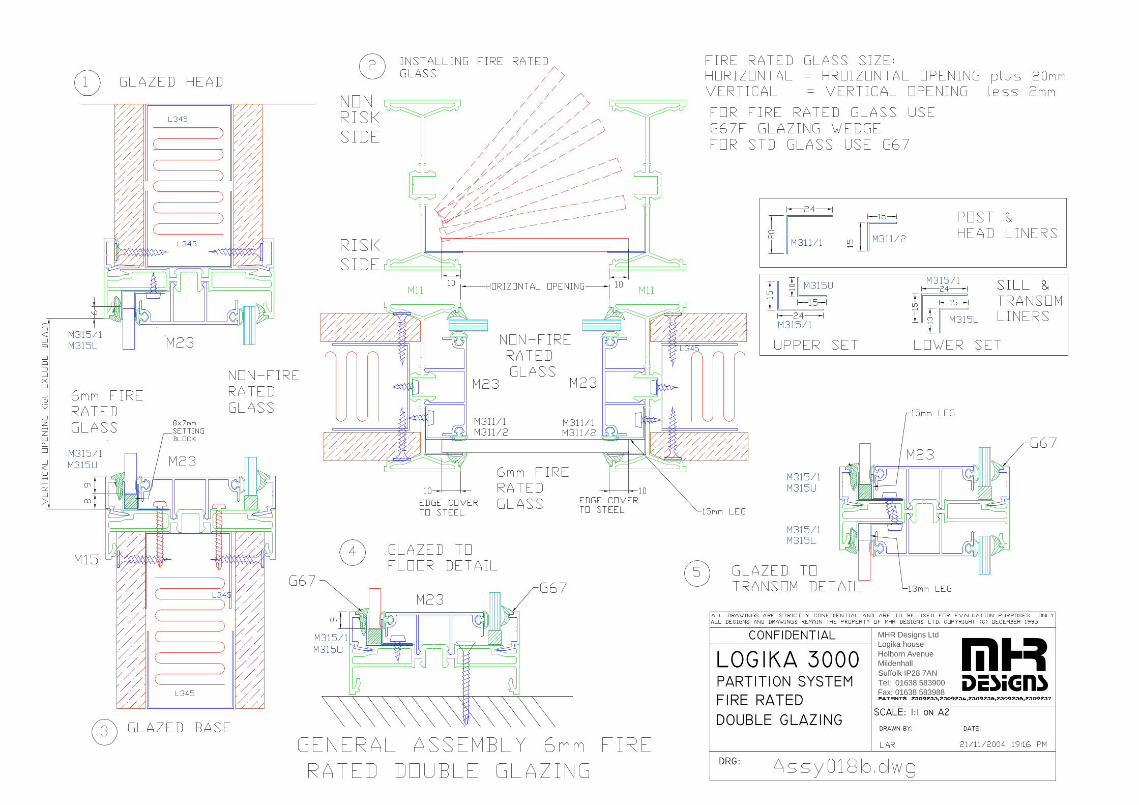
FIRE RATED
LOGIKA 3000 PARTITION SYSTEM
DOUBLE GLAZING
DRG:
CONFIDENTIAL
DRAWN BY:
SCALE: 1:1 on A2
DATE:
mhrdesigns
MHR Designs LtdLogika houseHolborn AvenueMildenhallSuffolk IP28 7ANTel: 01638 583900Fax: 01638 583988
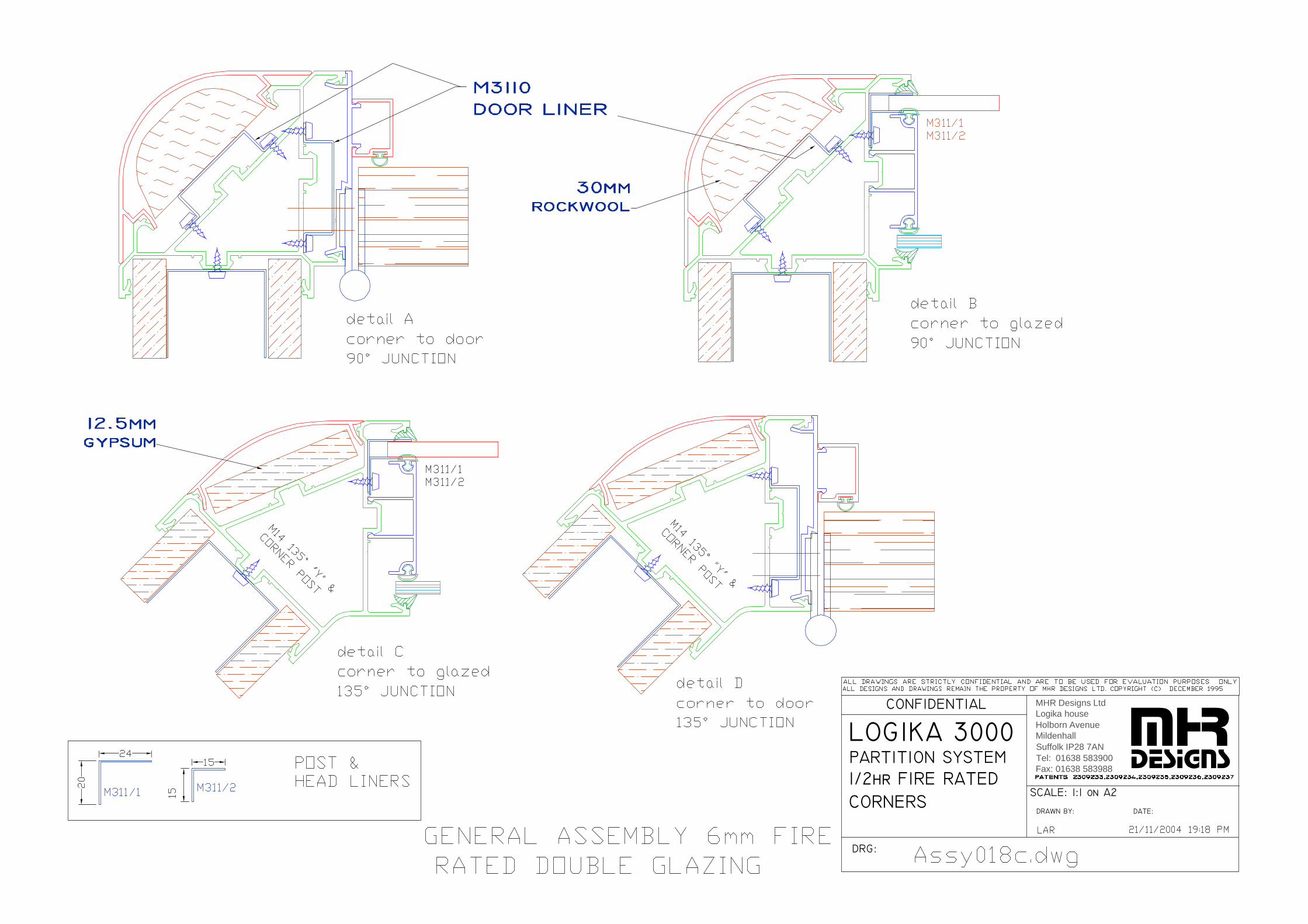
1/2hr FIRE RATED
LOGIKA 3000 PARTITION SYSTEM
CORNERS
DRG:
CONFIDENTIAL
DRAWN BY:
SCALE: 1:1 on A2
DATE:
mhrdesigns
MHR Designs LtdLogika houseHolborn AvenueMildenhallSuffolk IP28 7ANTel: 01638 583900Fax: 01638 583988
LOGIKA 3000 & LOGIKA 5000 SPECIFCATIONS LOGIKA 3000 & 5000-V7B.doc 26/09/2006
MHR DESIGNS LTD. Logika House, Holborn Avenue, Mildenhall, Suffolk, IP28 7AN Tel: 01638 583900 Fax: 01638 583988
Appendix 1
Section B
LOGIKA 5000
FRAMELESS Single glazed
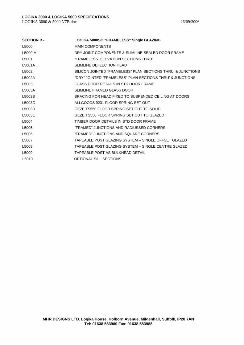
LOGIKA 3000 & LOGIKA 5000 SPECIFCATIONS LOGIKA 3000 & 5000-V7B.doc 26/09/2006
MHR DESIGNS LTD. Logika House, Holborn Avenue, Mildenhall, Suffolk, IP28 7AN Tel: 01638 583900 Fax: 01638 583988
SECTION B - LOGIKA 5000SG “FRAMELESS” Single GLAZING
L5000 MAIN COMPONENTS
L5000-A DRY JOINT COMPONENTS & SLIMLINE SEALED DOOR FRAME
L5001 “FRAMELESS” ELEVATION SECTIONS THRU’
L5001A SLIMLINE DEFLECTION HEAD
L5002 SILICON JOINTED “FRAMELESS” PLAN SECTIONS THRU’ & JUNCTIONS
L5002A “DRY” JOINTED “FRAMELESS” PLAN SECTIONS THRU’ & JUNCTIONS
L5003 GLASS DOOR DETAILS IN STD DOOR FRAME
L5003A SLIMLINE FRAMED GLASS DOOR
L5003B BRACING FOR HEAD FIXED TO SUSPENDED CEILING AT DOORS
L5003C ALLGOODS 9231 FLOOR SPRING SET OUT
L5003D GEZE TS550 FLOOR SPRING SET OUT TO SOLID
L5003E GEZE TS550 FLOOR SPRING SET OUT TO GLAZED
L5004 TIMBER DOOR DETAILS IN STD DOOR FRAME
L5005 “FRAMED” JUNCTIONS AND RADIUSSED CORNERS
L5006 “FRAMED” JUNCTIONS AND SQUARE CORNERS
L5007 TAPEABLE POST GLAZING SYSTEM – SINGLE OFFSET GLAZED
L5008 TAPEABLE POST GLAZING SYSTEM – SINGLE CENTRE GLAZED
L5009 TAPEABLE POST AS BULKHEAD DETAIL
L5010 OPTIONAL SILL SECTIONS

PARTITION GLAZING
LOGIKA 5000 "FRAMELESS"
MAIN COMPONENTS
DRG:
CONFIDENTIAL
SUFFOLK CB9 7YH
DRAWN BY:
FAX: 01440 710801TEL: 01440 710800
SCALE: 1:1 ON A4DATE:
MHR DESIGNS LTDBOUNDARY ROADHAVERHILL
L A Roth, MHR 29/09/2004 10:39 PM
L5000.dwg
M5001SLIMLINE HEADABUTMENT/POST
M5125INFILL FOR
M5001/M5012H
L231INSERT FORM5125/M5111
G4BACKSEAL
G67GLAZINGWEDGE
G2412SETTINGBLOCK
M5002SLIMLINEBASE &END POST
M5003SLIMLINEGLAZINGBEAD
M5001PVTDOOR PIVOTFor M5001Slimine head
M24SG12OFFSET GLAZING ADAPTERFOR LOGIKA 3000 HEAD & POSTS(M11,M12,M13,M14)& LOWER FACE OF M15 ONLY
M24SG12CENTRE GLAZED ADAPTER FORLOGIKA 3000 HEAD & POSTS(M11,M12,M13,M14)NOT M15
M125BBLANK INFILLFOR LOGIKA 3000 HEAD/POST
M51112PVTDOOR PIVOT
For M11/M12Standard head
LOGIKA 5000 - SLIMLINE 12mm GLAZING 12mm GLAZING COMPONENTS for LOGIKA 3000M5012HSLIMLINE DEFLECTION HEAD/ABUTMENT POST
M5012PVTDOOR PIVOTFor deflectionSlimine head
WE
DG
E F
AC
E
LH DOOR
WE
DG
E F
AC
E
RH DOOR
M500CAP/L & M500CAP/RLH & RH END CAPS FOR M5002 SILL@ DOOR OPENINGS
M15CTR12CENTRE GLAZED ADAPTER FORLOGIKA 3000 SILL M15
PATENTS: 2309233,2309234,2309235,2309236,2309237,2387856
M5123CHECK for AVAILABILITY BULLNOSE CAPPING FOR M5001/M5012H
M15SG12OFFSET 12mm GLAZINGUPPER ADAPTER FORLOGIKA 3000 SILL M15

LOGIKA 5000
DRG:
CONFIDENTIAL
SUFFOLK CB9 7YH
DRAWN BY:
FAX: 01440 710801TEL: 01440 710800
SCALE: 1:1DATE:
MHR DESIGNS LTDBOUNDARY ROADHAVERHILL
Lee A Roth 05/02/2004 07:43 PM
L5000-A.dwg
"DRY JOINT" COMPONENTS "SEALED" DOOR FRAME COMPONENTS
DETAIL Bdetail at "Frameless" dry joint 90° CORNER(sill level shown)NOTE:INNER SECTION BONDEDTO GLASS WITH CLEARUV CURE ADHESIVE atmid height
DETAIL Adetail at "Frameless" STRAIGHT JOINT(sill level shown)
DETAIL Cdetail at "Frameless" GHOST "dry joint" 3 way(sill level shown)
L231INSERT FORL5125 & M5111
G4PGLAZING/DOORFRAME SEAL
DRY JOINT COMPONENTSAND SLIMLINE DOORFRAME
FRAME ASSEMBLYMULLION - DOORSUPPORTED ONFLOOR PIVOT ANDTOP PIVOT ONLYside hung not applicable
Mullion lock or LatchAVAILABLE TO ORDER.
Floor lock available
PATENTS: 2309233,2309234,2309235,2309236,2309237,2387856
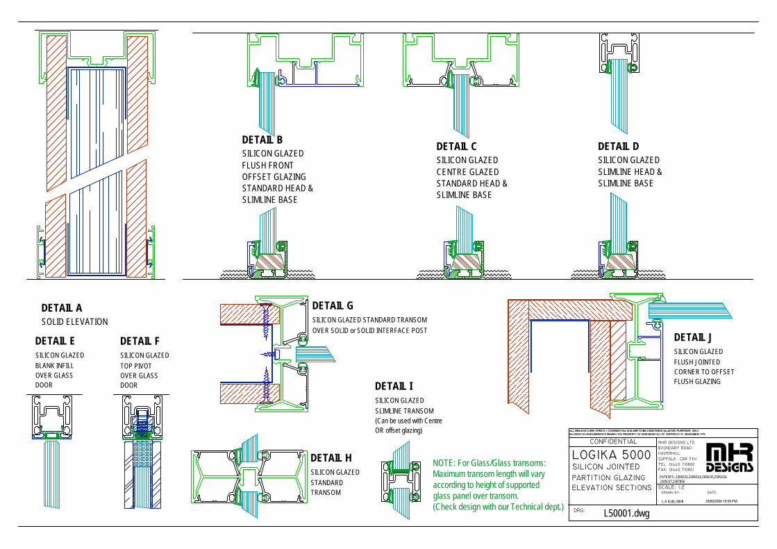
PARTITION GLAZING
LOGIKA 5000 SILICON JOINTED
ELEVATION SECTIONS
DRG:
CONFIDENTIAL
SUFFOLK CB9 7YH
DRAWN BY:
FAX: 01440 710801TEL: 01440 710800
SCALE: 1:2DATE:
MHR DESIGNS LTDBOUNDARY ROADHAVERHILL
L A Roth, MHR 20/09/2004 19:59 PM
L50001.dwg
DETAIL BSILICON GLAZEDFLUSH FRONTOFFSET GLAZINGSTANDARD HEAD &SLIMLINE BASE
DETAIL CSILICON GLAZEDCENTRE GLAZEDSTANDARD HEAD &SLIMLINE BASE
DETAIL DSILICON GLAZEDSLIMLINE HEAD &SLIMLINE BASE
DETAIL ESILICON GLAZEDBLANK INFILLOVER GLASSDOOR
DETAIL ASOLID ELEVATION
DETAIL FSILICON GLAZEDTOP PIVOTOVER GLASSDOOR DETAIL I
SILICON GLAZEDSLIMLINE TRANSOM(Can be used with CentreOR offset glazing)
DETAIL HSILICON GLAZEDSTANDARDTRANSOM
NOTE: For Glass/Glass transoms:Maximum transom length will varyaccording to height of supportedglass panel over transom.(Check design with our Technical dept.)
DETAIL GSILICON GLAZED STANDARD TRANSOMOVER SOLID or SOLID INTERFACE POST
DETAIL JSILICON GLAZEDFLUSH JOINTEDCORNER TO OFFSETFLUSH GLAZING
PATENTS: 2309233,2309234,2309235,2309236,2309237,2387856

LOGIKA 5000
DRG:
CONFIDENTIAL
SUFFOLK CB9 7YH
DRAWN BY:
FAX: 01440 710801TEL: 01440 710800
SCALE: 1:2 on A4DATE:
MHR DESIGNS LTDBOUNDARY ROADHAVERHILL
L A Roth, MHR 20/09/2004 19:58 PM
L50001A.dwg
DETAIL ATHE HIGHEST GLASSLEVEL IS DETERMINEDBY:MINIMUM EDGE CLEARANCE (3mm)specified in table 20 BS6262FIXING CLEARANCE to preventglass to fixing contact during installation (7.5mm)
DETAIL BWith Floor loaded and a10mm deflectionTHE LOWEST GLASSLEVEL IS DETERMINEDBY:MINIMUM EDGE COVER (9mm)as specified in table 14 of BS6262
CONCLUSIONThe minimum rebate depthto comply with the StandardsAND provide a 10mm vertical deflection tolerance is 22.5 mm.To prevent any fixing head coming into contact with the glass edge during installation an additional7.5mm fixing head clearance is required.The overall profile height must beat least 30mm to fully comply.
NOTE:This deflection detail can only apply to SILICON JOINTED glass runsDoors will follow the floor patch downward (varying the top clearanceof the door panel). Alternatively designers should consider the incorporationof a glass overpanel above a standard height door leaf.Over time it is assumed both Ceiling and floor will settle to a common level.
recess forhead fixing
DEFLECTION HEAD Silicon jointed glazingONLY
REV 1
PATENTS: 2309233,2309234,2309235,2309236,2309237,2387856
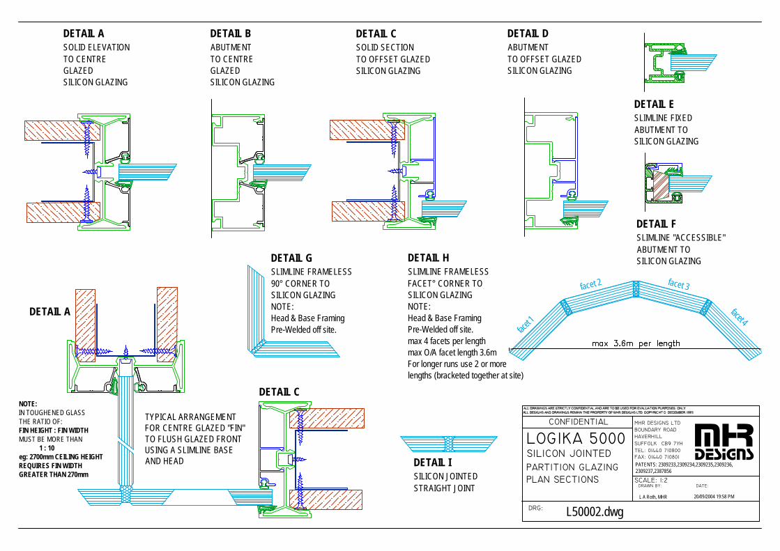
PARTITION GLAZING
LOGIKA 5000 SILICON JOINTED
PLAN SECTIONS
DRG:
CONFIDENTIAL
SUFFOLK CB9 7YH
DRAWN BY:
FAX: 01440 710801TEL: 01440 710800
SCALE: 1:2DATE:
MHR DESIGNS LTDBOUNDARY ROADHAVERHILL mhr
designs
L A Roth, MHR 20/09/2004 19:58 PM
L50002.dwg
DETAIL ASOLID ELEVATIONTO CENTREGLAZEDSILICON GLAZING
DETAIL BABUTMENTTO CENTREGLAZEDSILICON GLAZING
DETAIL CSOLID SECTIONTO OFFSET GLAZEDSILICON GLAZING
DETAIL DABUTMENTTO OFFSET GLAZEDSILICON GLAZING
DETAIL ESLIMLINE FIXEDABUTMENT TOSILICON GLAZING
DETAIL FSLIMLINE "ACCESSIBLE"ABUTMENT TOSILICON GLAZING
DETAIL A
DETAIL C
TYPICAL ARRANGEMENTFOR CENTRE GLAZED "FIN"TO FLUSH GLAZED FRONTUSING A SLIMLINE BASEAND HEAD
DETAIL GSLIMLINE FRAMELESS90° CORNER TOSILICON GLAZINGNOTE:Head & Base FramingPre-Welded off site.
NOTE:IN TOUGHENED GLASSTHE RATIO OF:FIN HEIGHT : FIN WIDTHMUST BE MORE THAN 1 : 10eg: 2700mm CEILING HEIGHTREQUIRES FIN WIDTHGREATER THAN 270mm
DETAIL HSLIMLINE FRAMELESSFACET° CORNER TOSILICON GLAZINGNOTE:Head & Base FramingPre-Welded off site.max 4 facets per lengthmax O/A facet length 3.6mFor longer runs use 2 or morelengths (bracketed together at site)
facet 1
facet 2 facet 3
facet 4
PATENTS: 2309233,2309234,2309235,2309236,2309237,2387856
DETAIL ISILICON JOINTEDSTRAIGHT JOINT
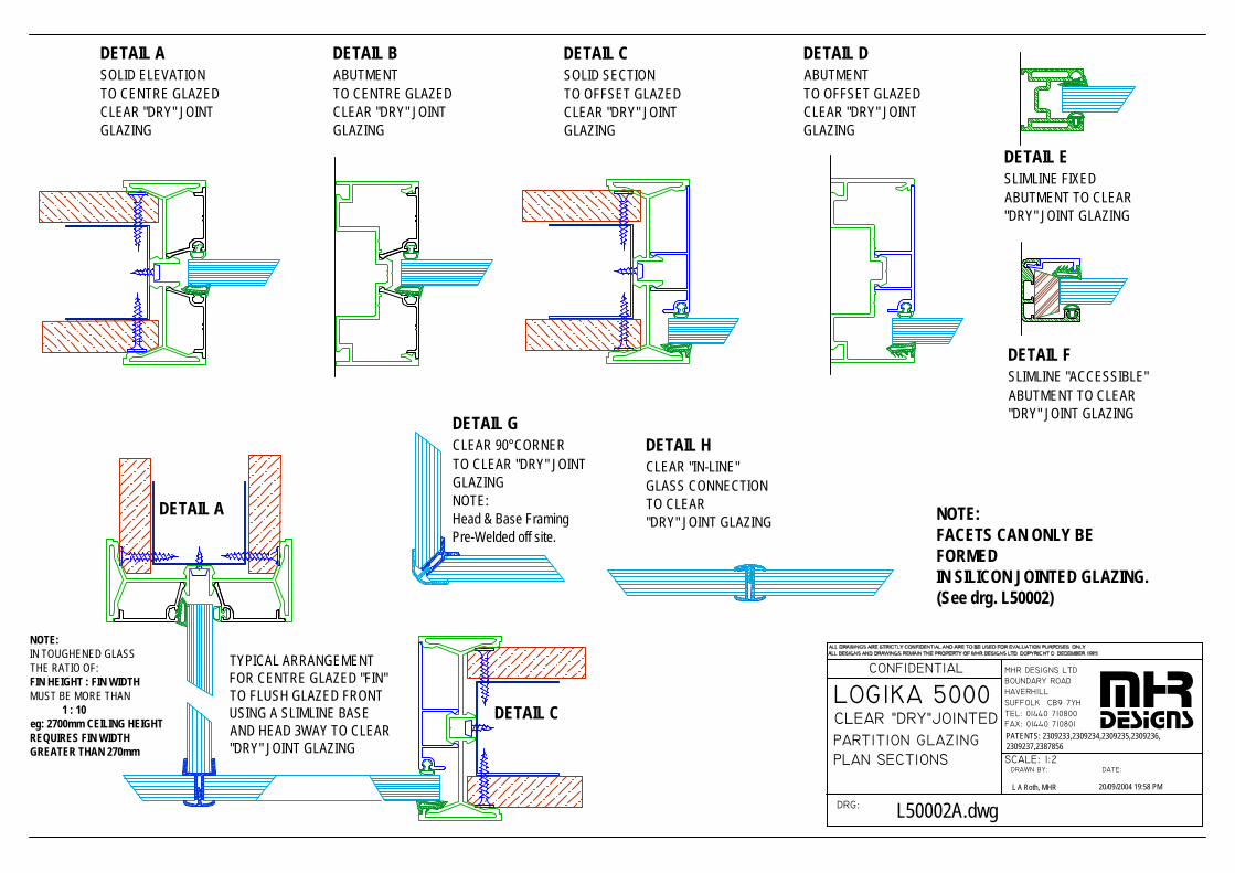
PARTITION GLAZING
LOGIKA 5000 CLEAR "DRY"JOINTED
PLAN SECTIONS
DRG:
CONFIDENTIAL
SUFFOLK CB9 7YH
DRAWN BY:
FAX: 01440 710801TEL: 01440 710800
SCALE: 1:2DATE:
MHR DESIGNS LTDBOUNDARY ROADHAVERHILL mhr
designs
L A Roth, MHR 20/09/2004 19:58 PM
L50002A.dwg
DETAIL ASOLID ELEVATIONTO CENTRE GLAZEDCLEAR "DRY" JOINTGLAZING
DETAIL BABUTMENTTO CENTRE GLAZEDCLEAR "DRY" JOINTGLAZING
DETAIL CSOLID SECTIONTO OFFSET GLAZEDCLEAR "DRY" JOINTGLAZING
DETAIL DABUTMENTTO OFFSET GLAZEDCLEAR "DRY" JOINTGLAZING
DETAIL ESLIMLINE FIXEDABUTMENT TO CLEAR"DRY" JOINT GLAZING
DETAIL FSLIMLINE "ACCESSIBLE"ABUTMENT TO CLEAR"DRY" JOINT GLAZING
DETAIL A
DETAIL C
TYPICAL ARRANGEMENTFOR CENTRE GLAZED "FIN"TO FLUSH GLAZED FRONTUSING A SLIMLINE BASEAND HEAD 3WAY TO CLEAR"DRY" JOINT GLAZING
DETAIL GCLEAR 90°CORNERTO CLEAR "DRY" JOINTGLAZINGNOTE:Head & Base FramingPre-Welded off site.
NOTE:IN TOUGHENED GLASSTHE RATIO OF:FIN HEIGHT : FIN WIDTHMUST BE MORE THAN 1 : 10eg: 2700mm CEILING HEIGHTREQUIRES FIN WIDTHGREATER THAN 270mm
DETAIL HCLEAR "IN-LINE"GLASS CONNECTIONTO CLEAR"DRY" JOINT GLAZING
PATENTS: 2309233,2309234,2309235,2309236,2309237,2387856
NOTE:FACETS CAN ONLY BEFORMEDIN SILICON JOINTED GLAZING.(See drg. L50002)
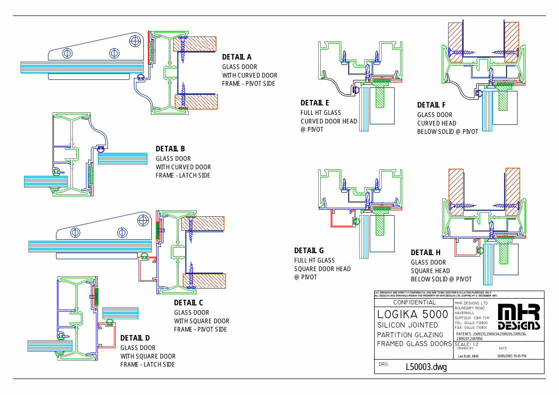
PARTITION GLAZING
LOGIKA 5000 SILICON JOINTED
FRAMED GLASS DOORS
DRG:
CONFIDENTIAL
SUFFOLK CB9 7YH
DRAWN BY:
FAX: 01440 710801TEL: 01440 710800
SCALE: 1:2DATE:
MHR DESIGNS LTDBOUNDARY ROADHAVERHILL mhr
designs
Lee Roth, MHR 30/06/2003 10:45 PM
L50003.dwg
DETAIL AGLASS DOORWITH CURVED DOORFRAME - PIVOT SIDE
DETAIL EFULL HT GLASSCURVED DOOR HEAD@ PIVOT
DETAIL FGLASS DOOR CURVED HEADBELOW SOLID @ PIVOT
DETAIL BGLASS DOORWITH CURVED DOORFRAME - LATCH SIDE
DETAIL CGLASS DOORWITH SQUARE DOORFRAME - PIVOT SIDE
DETAIL DGLASS DOORWITH SQUARE DOORFRAME - LATCH SIDE
DETAIL GFULL HT GLASSSQUARE DOOR HEAD@ PIVOT
DETAIL HGLASS DOOR SQUARE HEADBELOW SOLID @ PIVOT
PATENTS: 2309233,2309234,2309235,2309236,2309237,2387856
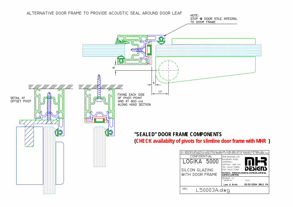
WITH DOOR FRAME
DRG:
CONFIDENTIAL
SUFFOLK CB9 7YH
DRAWN BY:SCALE: 1:1
TEL: 01440 710800FAX: 01440 710801
DATE:
HAVERHILLBOUNDARY ROADMHR DESIGNS LTD
SILCON GLAZING
ALTERNATIVE DOOR FRAME TO PROVIDE ACOUSTIC SEAL AROUND DOOR LEAF
"SEALED" DOOR FRAME COMPONENTS(CHECK availabilty of pivots for slimline door frame with MHR )
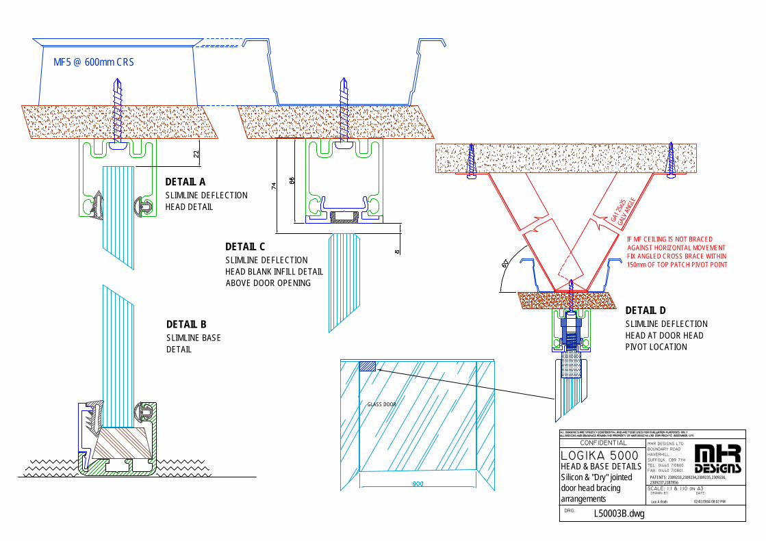
LOGIKA 5000
DRG:
CONFIDENTIAL
SUFFOLK CB9 7YH
DRAWN BY:
FAX: 01440 710801TEL: 01440 710800
SCALE: 1:1 & 1:10 on A3DATE:
MHR DESIGNS LTDBOUNDARY ROADHAVERHILL
Lee A Roth 02/02/2004 08:02 PM
L50003B.dwg
DETAIL ASLIMLINE DEFLECTIONHEAD DETAIL
HEAD & BASE DETAILS Silicon & "Dry" jointed door head bracingarrangements
DETAIL CSLIMLINE DEFLECTIONHEAD BLANK INFILL DETAILABOVE DOOR OPENING
DETAIL DSLIMLINE DEFLECTIONHEAD AT DOOR HEADPIVOT LOCATION
DETAIL BSLIMLINE BASE DETAIL
MF5 @ 600mm CRS
GA1 2
5x25
GALV
ANG
LE
IF MF CEILING IS NOT BRACEDAGAINST HORIZONTAL MOVEMENTFIX ANGLED CROSS BRACE WITHIN150mm OF TOP PATCH PIVOT POINT
GLASS DOOR
PATENTS: 2309233,2309234,2309235,2309236,2309237,2387856
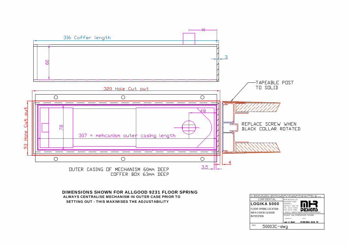
DIMENSIONS SHOWN FOR ALLGOOD 9231 FLOOR SPRINGALWAYS CENTRALISE MECHANISM IN OUTER CASE PRIOR TO
SETTING OUT - THIS MAXIMISES THE ADJUSTABILITY
DRG:
CONFIDENTIAL
SUFFOLK CB9 7YH
DRAWN BY:
FAX: 01440 710801TEL: 01440 710800
SCALE: use DIMENSIONS SHOWN
DATE:
MHR DESIGNS LTDBOUNDARY ROADHAVERHILLLOGIKA 5000
FLOOR SPRING LOCATIONWITH COVERS & DOORIN POSITION
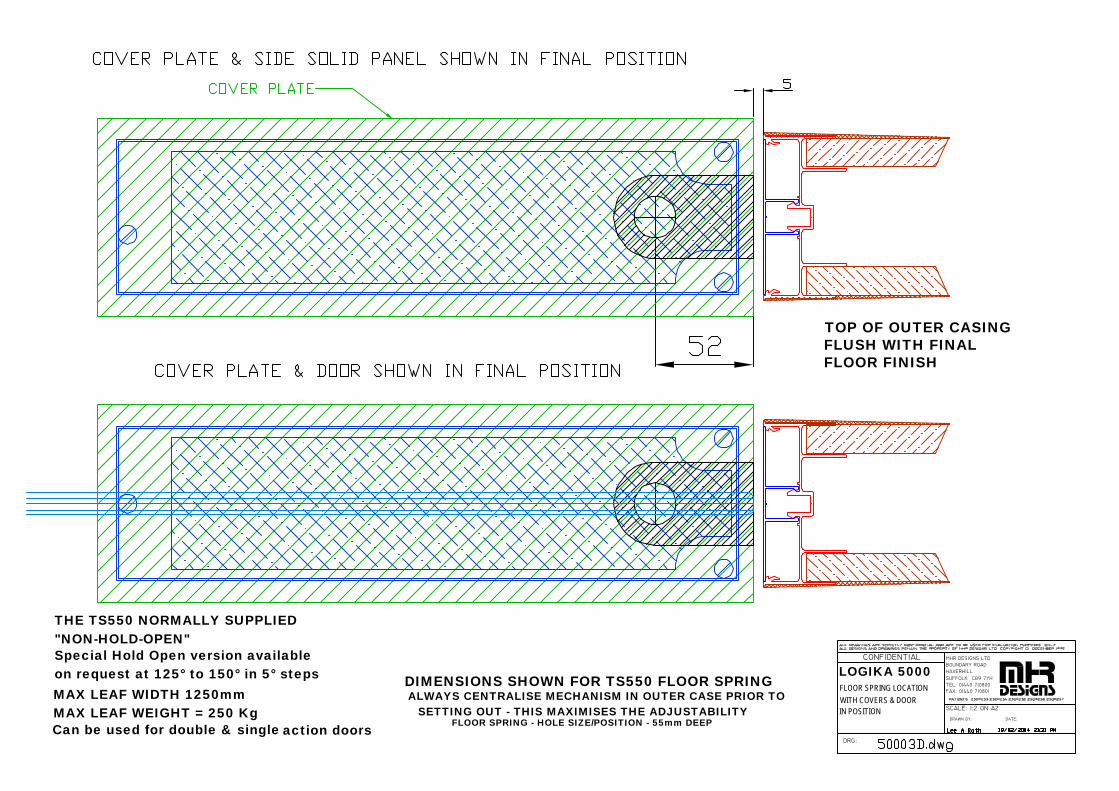
TOP OF OUTER CASINGFLUSH WITH FINALFLOOR FINISH
THE TS550 NORMALLY SUPPLIED"NON-HOLD-OPEN"Special Hold Open version availableon request at 125° to 150° in 5° stepsMAX LEAF WIDTH 1250mmMAX LEAF WEIGHT = 250 KgCan be used for double & single action doors
DRG:
CONFIDENTIAL
SUFFOLK CB9 7YH
DRAWN BY:
FAX: 01440 710801TEL: 01440 710800
SCALE: 1:2 ON A2
DATE:
MHR DESIGNS LTDBOUNDARY ROADHAVERHILL
FLOOR SPRING - HOLE SIZE/POSITION - 55mm DEEP
DIMENSIONS SHOWN FOR TS550 FLOOR SPRINGALWAYS CENTRALISE MECHANISM IN OUTER CASE PRIOR TO
SETTING OUT - THIS MAXIMISES THE ADJUSTABILITY
LOGIKA 5000FLOOR SPRING LOCATIONWITH COVERS & DOORIN POSITION
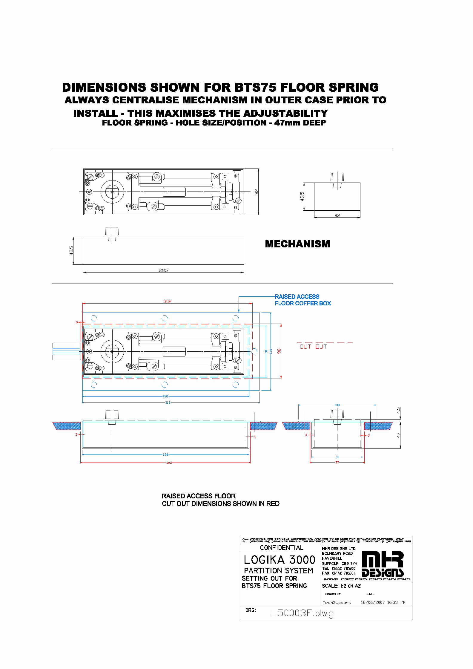
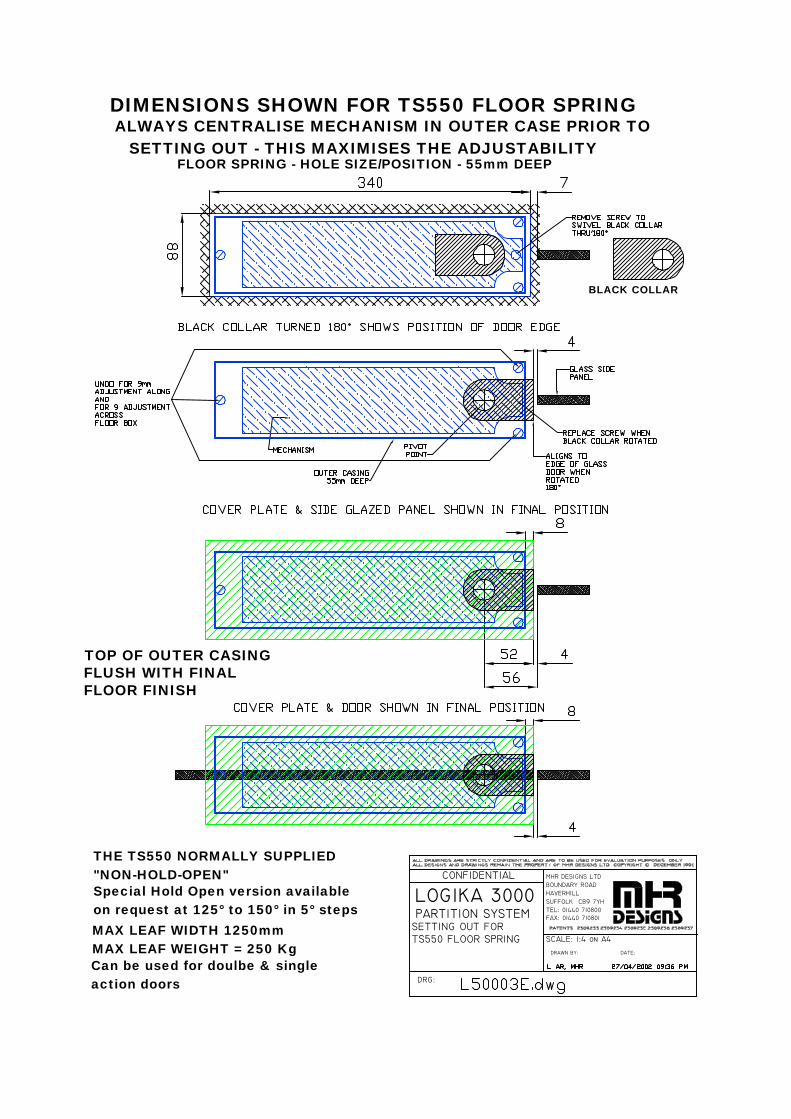
TS550 FLOOR SPRINGSETTING OUT FOR
LOGIKA 3000 PARTITION SYSTEM
DRG:
CONFIDENTIAL
SUFFOLK CB9 7YH
DRAWN BY:
FAX: 01440 710801TEL: 01440 710800
SCALE: 1:4 on A4
DATE:
MHR DESIGNS LTDBOUNDARY ROADHAVERHILL
FLOOR SPRING - HOLE SIZE/POSITION - 55mm DEEP
DIMENSIONS SHOWN FOR TS550 FLOOR SPRING
BLACK COLLAR
TOP OF OUTER CASINGFLUSH WITH FINALFLOOR FINISH
THE TS550 NORMALLY SUPPLIED"NON-HOLD-OPEN"Special Hold Open version availableon request at 125° to 150° in 5° stepsMAX LEAF WIDTH 1250mmMAX LEAF WEIGHT = 250 KgCan be used for doulbe & singleaction doors
ALWAYS CENTRALISE MECHANISM IN OUTER CASE PRIOR TO SETTING OUT - THIS MAXIMISES THE ADJUSTABILITY
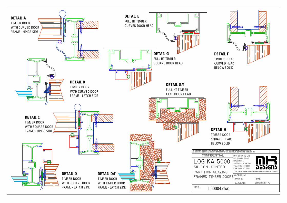
PARTITION GLAZING
LOGIKA 5000 SILICON JOINTED
FRAMED TIMBER DOORS
DRG:
CONFIDENTIAL
SUFFOLK CB9 7YH
DRAWN BY:
FAX: 01440 710801TEL: 01440 710800
SCALE: 1:2
DATE:
MHR DESIGNS LTDBOUNDARY ROADHAVERHILL mhr
designs
L A Roth, MHR 20/09/2004 20:11 PM
L50004.dwg
DETAIL ATIMBER DOORWITH CURVED DOORFRAME - HINGE SIDE
DETAIL EFULL HT TIMBERCURVED DOOR HEAD
DETAIL FTIMBER DOOR CURVED HEADBELOW SOLID
DETAIL BTIMBER DOORWITH CURVED DOORFRAME - LATCH SIDE
DETAIL CTIMBER DOORWITH SQUARE DOORFRAME - HINGE SIDE
DETAIL DTIMBER DOORWITH SQUARE DOORFRAME - LATCH SIDE
DETAIL GFULL HT TIMBERSQUARE DOOR HEAD
DETAIL HTIMBER DOOR SQUARE HEADBELOW SOLID
DETAIL G/TFULL HT TIMBERCLAD DOOR HEAD
DETAIL D/TTIMBER DOORWITH TIMBER DOORFRAME - LATCH SIDE
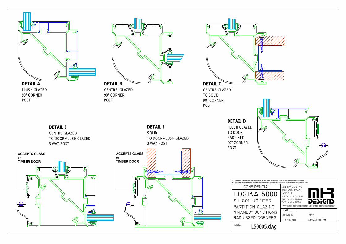
PARTITION GLAZING
LOGIKA 5000 SILICON JOINTED
"FRAMED" JUNCTIONS
DRG:
CONFIDENTIAL
SUFFOLK CB9 7YH
DRAWN BY:
FAX: 01440 710801TEL: 01440 710800
SCALE: 1:2
DATE:
MHR DESIGNS LTDBOUNDARY ROADHAVERHILL mhr
designs
L A Roth, MHR 20/09/2004 20:07 PM
L50005.dwg
DETAIL AFLUSH GLAZED90° CORNERPOST
DETAIL BCENTRE GLAZED90° CORNERPOST
DETAIL CCENTRE GLAZEDTO SOLID90° CORNERPOST
DETAIL DFLUSH GLAZEDTO DOORRADIUSED 90° CORNERPOST
DETAIL ECENTRE GLAZEDTO DOOR/FLUSH GLAZED3 WAY POST
DETAIL FSOLIDTO DOOR/FLUSH GLAZED3 WAY POST
RADIUSSED CORNERS
ACCEPTS GLASSorTIMBER DOOR
ACCEPTS GLASSorTIMBER DOOR
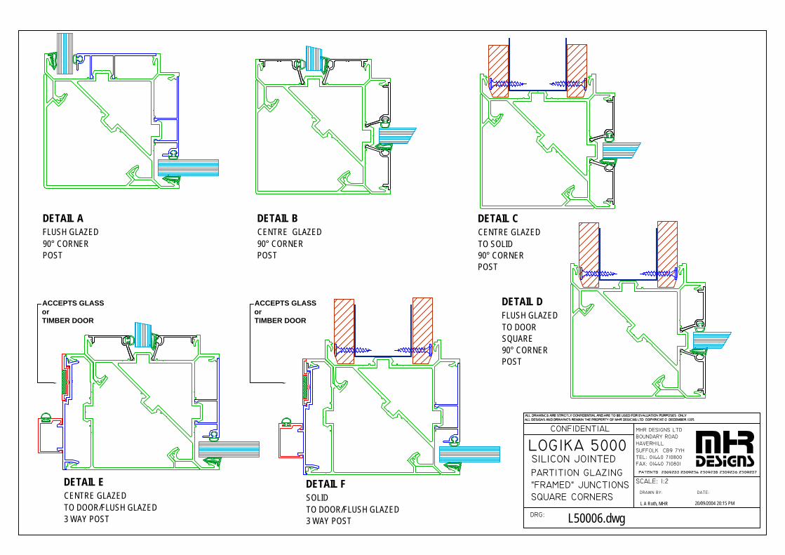
LOGIKA 5000
DRG:
CONFIDENTIAL
SUFFOLK CB9 7YH
DRAWN BY:
FAX: 01440 710801TEL: 01440 710800
SCALE: 1:2
DATE:
MHR DESIGNS LTDBOUNDARY ROADHAVERHILL mhr
designs
L A Roth, MHR 20/09/2004 20:15 PM
L50006.dwg
DETAIL AFLUSH GLAZED90° CORNERPOST
DETAIL BCENTRE GLAZED90° CORNERPOST
DETAIL CCENTRE GLAZEDTO SOLID90° CORNERPOST
DETAIL DFLUSH GLAZEDTO DOORSQUARE90° CORNERPOST
DETAIL FSOLIDTO DOOR/FLUSH GLAZED3 WAY POST
DETAIL ECENTRE GLAZEDTO DOOR/FLUSH GLAZED3 WAY POST
ACCEPTS GLASSorTIMBER DOOR
ACCEPTS GLASSorTIMBER DOOR
"FRAMED" JUNCTIONSSQUARE CORNERS
SILICON JOINTEDPARTITION GLAZING
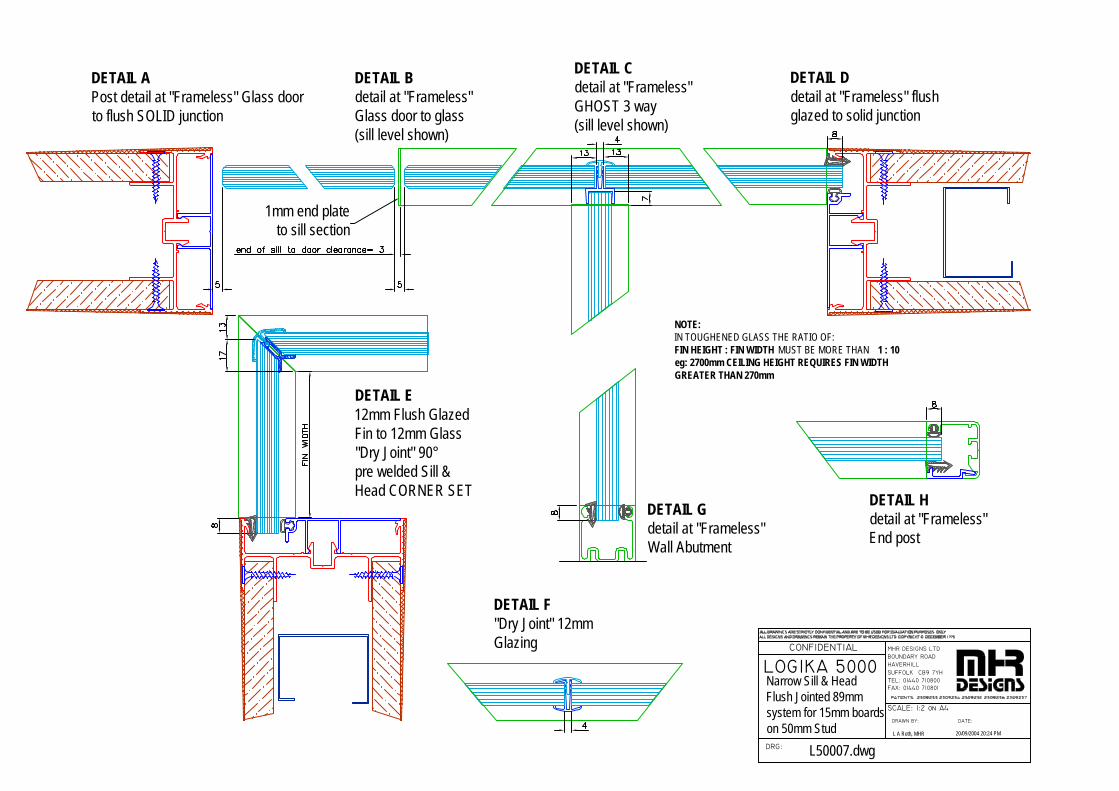
LOGIKA 5000
DRG:
CONFIDENTIAL
SUFFOLK CB9 7YH
DRAWN BY:
FAX: 01440 710801TEL: 01440 710800
SCALE: 1:2 on A4
DATE:
MHR DESIGNS LTDBOUNDARY ROADHAVERHILL
L A Roth, MHR 20/09/2004 20:24 PM
L50007.dwg
Narrow Sill & HeadFlush Jointed 89mmsystem for 15mm boardson 50mm Stud
NOTE:IN TOUGHENED GLASS THE RATIO OF:FIN HEIGHT : FIN WIDTH MUST BE MORE THAN 1 : 10eg: 2700mm CEILING HEIGHT REQUIRES FIN WIDTHGREATER THAN 270mm
DETAIL APost detail at "Frameless" Glass door to flush SOLID junction
1mm end plateto sill section
DETAIL F"Dry Joint" 12mmGlazing
DETAIL E12mm Flush GlazedFin to 12mm Glass "Dry Joint" 90°pre welded Sill &Head CORNER SET
DETAIL Bdetail at "Frameless"Glass door to glass(sill level shown)
DETAIL Cdetail at "Frameless" GHOST 3 way(sill level shown)
DETAIL Ddetail at "Frameless" flushglazed to solid junction
DETAIL Gdetail at "Frameless" Wall Abutment
DETAIL Hdetail at "Frameless" End post

LOGIKA 5000
DRG:
CONFIDENTIAL
SUFFOLK CB9 7YH
DRAWN BY:
FAX: 01440 710801TEL: 01440 710800
SCALE: 1:2 on A4
DATE:
MHR DESIGNS LTDBOUNDARY ROADHAVERHILL
L A Roth, MHR 20/09/2004 20:19 PM
L50008.dwg
Narrow Sill & HeadFlush Jointed 89mmsystem for 15mm boardson 50mm Stud
NOTE:IN TOUGHENED GLASS THE RATIO OF:FIN HEIGHT : FIN WIDTH MUST BE MORE THAN 1 : 10eg: 2700mm CEILING HEIGHT REQUIRES FIN WIDTHGREATER THAN 270mm
DETAIL APost detail at "Frameless" Glass door to flush SOLID junction
1mm end plateto sill section
DETAIL F"Dry Joint" 12mmGlazing
DETAIL E12mm Centre GlazedFin to 12mm Glass "Dry Joint" 90°pre welded Sill &Head
DETAIL Bdetail at "Frameless"Glass door to glass(sill level shown)
DETAIL Cdetail at "Frameless" GHOST 3 way(sill level shown)
DETAIL Ddetail at "Frameless" fluish centre glazed to solid junction
DETAIL Gdetail at "Frameless" Wall Abutment
DETAIL Hdetail at "Frameless" End post

LOGIKA 5000
DRG:
CONFIDENTIAL
SUFFOLK CB9 7YH
DRAWN BY:
FAX: 01440 710801TEL: 01440 710800
SCALE: 1:1 on A4
DATE:
MHR DESIGNS LTDBOUNDARY ROADHAVERHILL
L A Roth, MHR 20/09/2004 20:21 PM
L50009.dwg
Bulkhead Detail
DETAIL AModified TapeablePost as Bulkhead detailCompatible with allLogika 3000 & 5000components
M53100FLUSH GLAZING
ADAPTER FORLOGIKA 5000/3000SOLID MULLION POSTBULKHEAD TRANSOM
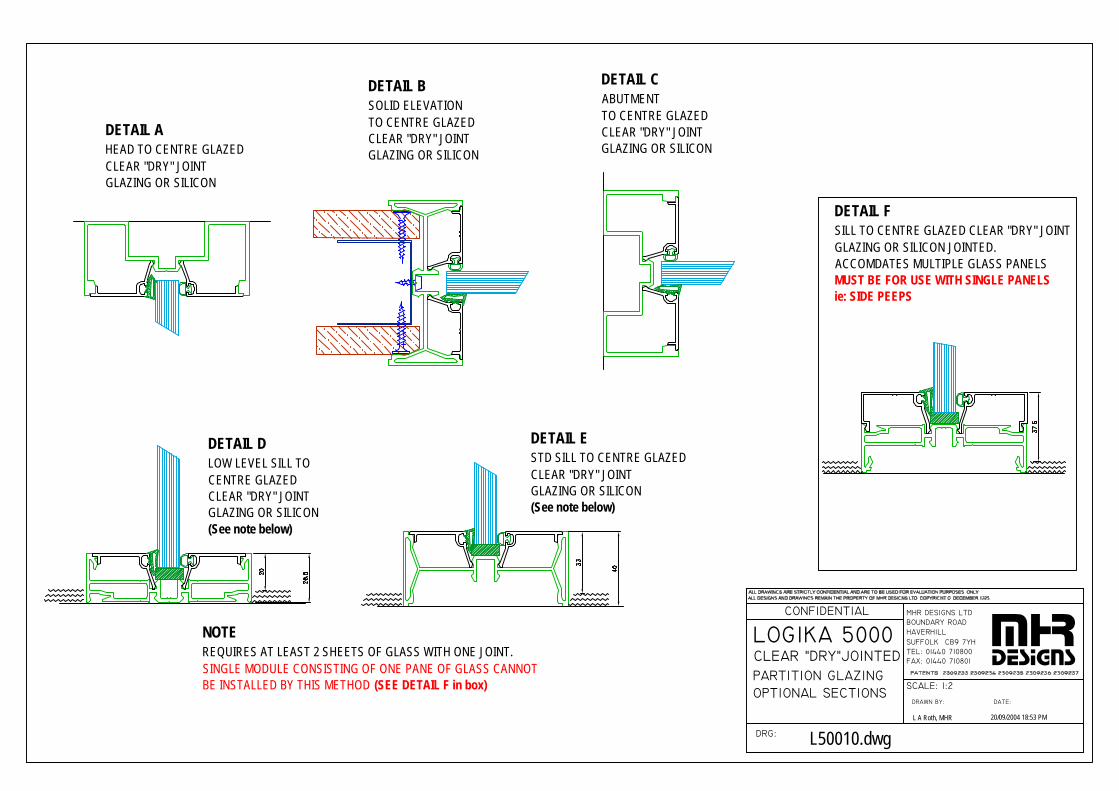
PARTITION GLAZING
LOGIKA 5000 CLEAR "DRY"JOINTED
OPTIONAL SECTIONS
DRG:
CONFIDENTIAL
SUFFOLK CB9 7YH
DRAWN BY:
FAX: 01440 710801TEL: 01440 710800
SCALE: 1:2
DATE:
MHR DESIGNS LTDBOUNDARY ROADHAVERHILL mhr
designs
L A Roth, MHR 20/09/2004 18:53 PM
L50010.dwg
DETAIL BSOLID ELEVATIONTO CENTRE GLAZEDCLEAR "DRY" JOINTGLAZING OR SILICON
DETAIL CABUTMENTTO CENTRE GLAZEDCLEAR "DRY" JOINTGLAZING OR SILICON
DETAIL AHEAD TO CENTRE GLAZEDCLEAR "DRY" JOINTGLAZING OR SILICON
DETAIL ESTD SILL TO CENTRE GLAZEDCLEAR "DRY" JOINTGLAZING OR SILICON(See note below)
DETAIL DLOW LEVEL SILL TO CENTRE GLAZEDCLEAR "DRY" JOINTGLAZING OR SILICON(See note below)
NOTEREQUIRES AT LEAST 2 SHEETS OF GLASS WITH ONE JOINT.SINGLE MODULE CONSISTING OF ONE PANE OF GLASS CANNOTBE INSTALLED BY THIS METHOD (SEE DETAIL F in box)
DETAIL FSILL TO CENTRE GLAZED CLEAR "DRY" JOINTGLAZING OR SILICON JOINTED.ACCOMDATES MULTIPLE GLASS PANELSMUST BE FOR USE WITH SINGLE PANELSie: SIDE PEEPS
LOGIKA 3000 & LOGIKA 5000 SPECIFCATIONS LOGIKA 3000 & 5000-V7B.doc 26/09/2006
MHR DESIGNS LTD. Logika House, Holborn Avenue, Mildenhall, Suffolk, IP28 7AN Tel: 01638 583900 Fax: 01638 583988
Appendix 1
Section C
LOGIKA 50000
DOUBLE GLAZED
LOGIKA 3000 & LOGIKA 5000 SPECIFCATIONS LOGIKA 3000 & 5000-V7B.doc 26/09/2006
MHR DESIGNS LTD. Logika House, Holborn Avenue, Mildenhall, Suffolk, IP28 7AN Tel: 01638 583900 Fax: 01638 583988
SECTION C - LOGIKA 5000DG “FRAMELESS” DOUBLE GLAZING COMPONENTS
WITH “Spectar ®” Ghost post
L5000DG MAIN COMPONENTS
L5001DG “FRAMELESS” ELEVATION SECTIONS THRU’
L5002DG-A “FRAMELESS” PLAN SECTIONS THRU’ & JUNCTIONS
L5002DG-B “FRAMELESS” PLAN SECTIONS WITH “DDA” JUNCTIONS
L5003DG JUNCTION POSTS AND FIN JOINT DETAILS
L5004DG 3 WAY AND CORNER POSTS FOR FRAMED DOORS
L5005DG-A FRAMELESS GLASS DOOR IN ACOUSTIC DOOR FRAME
L5005DG-B FRAMED DOUBLE GLASS DOOR IN STD FRAME
L5006DG TIMBER DOOR DETAILS IN TIMBER DOOR FRAME

DOUBLE GLAZING
LOGIKA 5000 GHOST POST
MAIN COMPONENTS
DRG:
CONFIDENTIAL
SUFFOLK CB9 7YH
DRAWN BY:
FAX: 01440 710801TEL: 01440 710800
SCALE: 1:1 ON A4
DATE:
MHR DESIGNS LTDBOUNDARY ROADHAVERHILL
Lee A Roth 19/02/2004 01:19 PM
5000DG.dwg
G4PGLAZING SEAL
G67TGLAZINGWEDGE
M53100TAPEABLE FLUSH GLAZING
ADAPTER FORLOGIKA 5000/3000SOLID MULLION POSTBULKHEAD TRANSOM
M12HSTANDARD HEADSECTION
M11GP"CLEAR" GHOST POSTincl DRY JOINT PROFILES
M23PDOUBLE GLAZINGINNER
M15STANDARD SILLSECTION
M513KCLEAR 90°DRY JOINTCORNER
G888 x 8 SETTINGBLOCK
M11STANDARD POST
FOR LOGIKA 3000
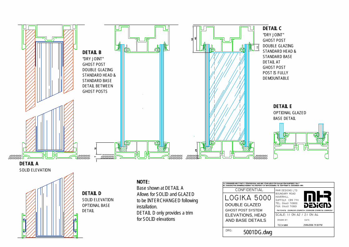
LOGIKA 5000
DRG:
CONFIDENTIAL
SUFFOLK CB9 7YH
DRAWN BY:
FAX: 01440 710801TEL: 01440 710800
SCALE: 1:1 ON A2 / 2:1 ON A4
DATE:
MHR DESIGNS LTDBOUNDARY ROADHAVERHILL mhr
designs
TECH MHR 29/06/2006 19:38 PM
5001DG.dwg
DETAIL ASOLID ELEVATION
DETAIL C"DRY JOINT"GHOST POSTDOUBLE GLAZINGSTANDARD HEAD &STANDARD BASEDETAIL ATGHOST POSTPOST IS FULLYDEMOUNTABLE
DETAIL B"DRY JOINT"GHOST POSTDOUBLE GLAZINGSTANDARD HEAD &STANDARD BASEDETAIL BETWEENGHOST POSTS
DETAIL DSOLID ELEVATIONOPTIONAL BASEDETAIL
NOTE:Base shown at DETAIL AAllows for SOLID and GLAZEDto be INTERCHANGED followinginstallation.DETAIL D only provides a trimfor SOLID elevations
DOUBLE GLAZEDGHOST POST SYSTEM
ELEVATIONS, HEADAND BASE DETAILS
DETAIL EOPTIONAL GLAZED BASE DETAIL
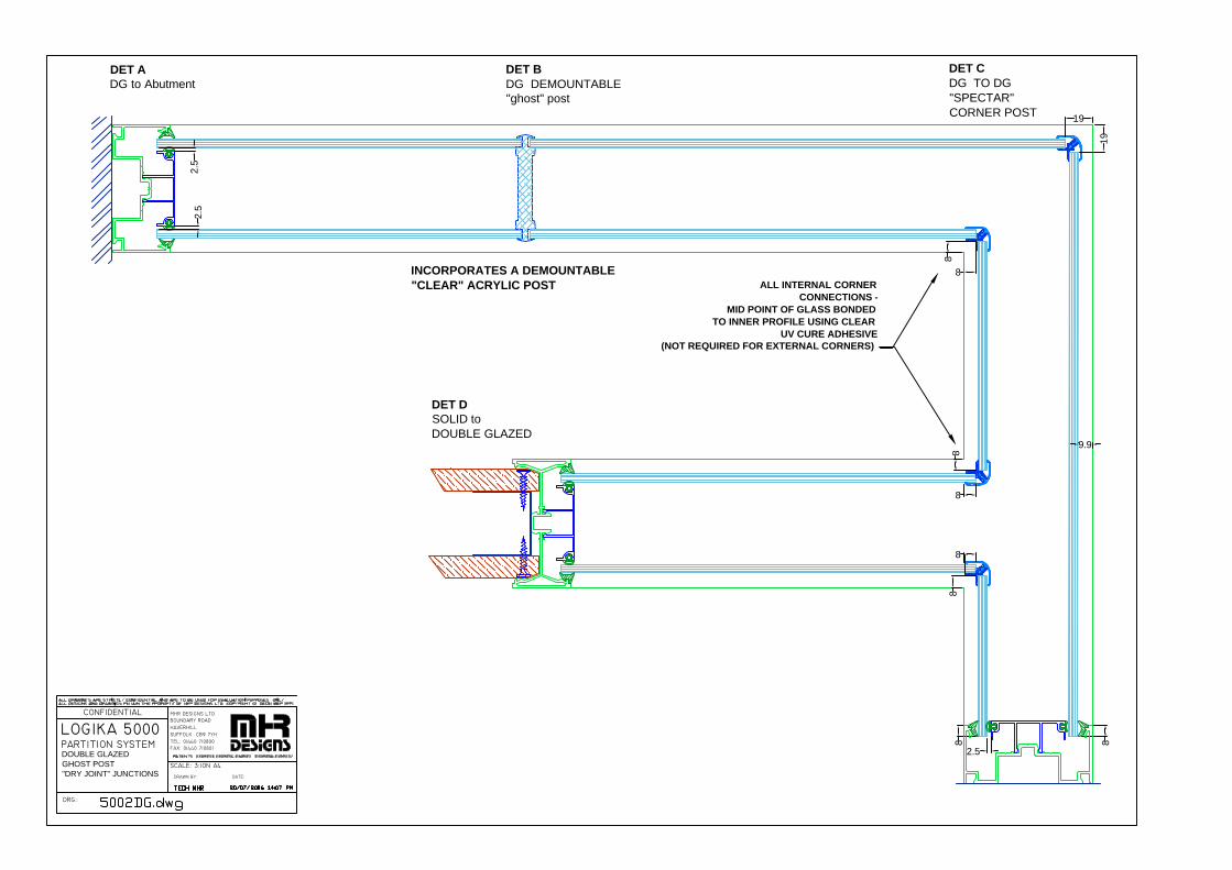
LOGIKA 5000 PARTITION SYSTEM
DRG:
CONFIDENTIAL
SUFFOLK CB9 7YH
DRAWN BY:
SCALE: 3:1ON A4
TEL: 01440 710800FAX: 01440 710801
DATE:
HAVERHILLBOUNDARY ROADMHR DESIGNS LTD
DET ADG to Abutment
DET BDG DEMOUNTABLE"ghost" post
INCORPORATES A DEMOUNTABLE"CLEAR" ACRYLIC POST
DET CDG TO DG"SPECTAR"CORNER POST
DOUBLE GLAZEDGHOST POST"DRY JOINT" JUNCTIONS
8 8
2.5
8
8
8
8
2.5
2.5
8
8
19
19
9.9
ALL INTERNAL CORNERCONNECTIONS -
MID POINT OF GLASS BONDEDTO INNER PROFILE USING CLEAR
UV CURE ADHESIVE(NOT REQUIRED FOR EXTERNAL CORNERS)
DET DSOLID toDOUBLE GLAZED
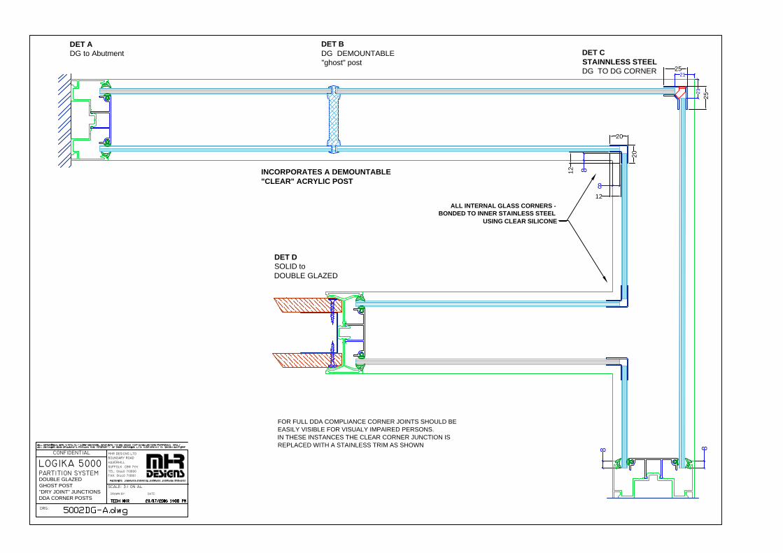
LOGIKA 5000 PARTITION SYSTEM
DRG:
CONFIDENTIAL
SUFFOLK CB9 7YH
DRAWN BY:
SCALE: 3:1 ON A4
TEL: 01440 710800FAX: 01440 710801
DATE:
HAVERHILLBOUNDARY ROADMHR DESIGNS LTD
DET ADG to Abutment
DET BDG DEMOUNTABLE"ghost" post
INCORPORATES A DEMOUNTABLE"CLEAR" ACRYLIC POST
DET CSTAINNLESS STEELDG TO DG CORNER
DOUBLE GLAZEDGHOST POST"DRY JOINT" JUNCTIONSDDA CORNER POSTS
8 8
ALL INTERNAL GLASS CORNERS -BONDED TO INNER STAINLESS STEEL
USING CLEAR SILICONE
DET DSOLID toDOUBLE GLAZED
25
25
21
21
8
8
20
20
12
12
FOR FULL DDA COMPLIANCE CORNER JOINTS SHOULD BEEASILY VISIBLE FOR VISUALY IMPAIRED PERSONS.IN THESE INSTANCES THE CLEAR CORNER JUNCTION ISREPLACED WITH A STAINLESS TRIM AS SHOWN
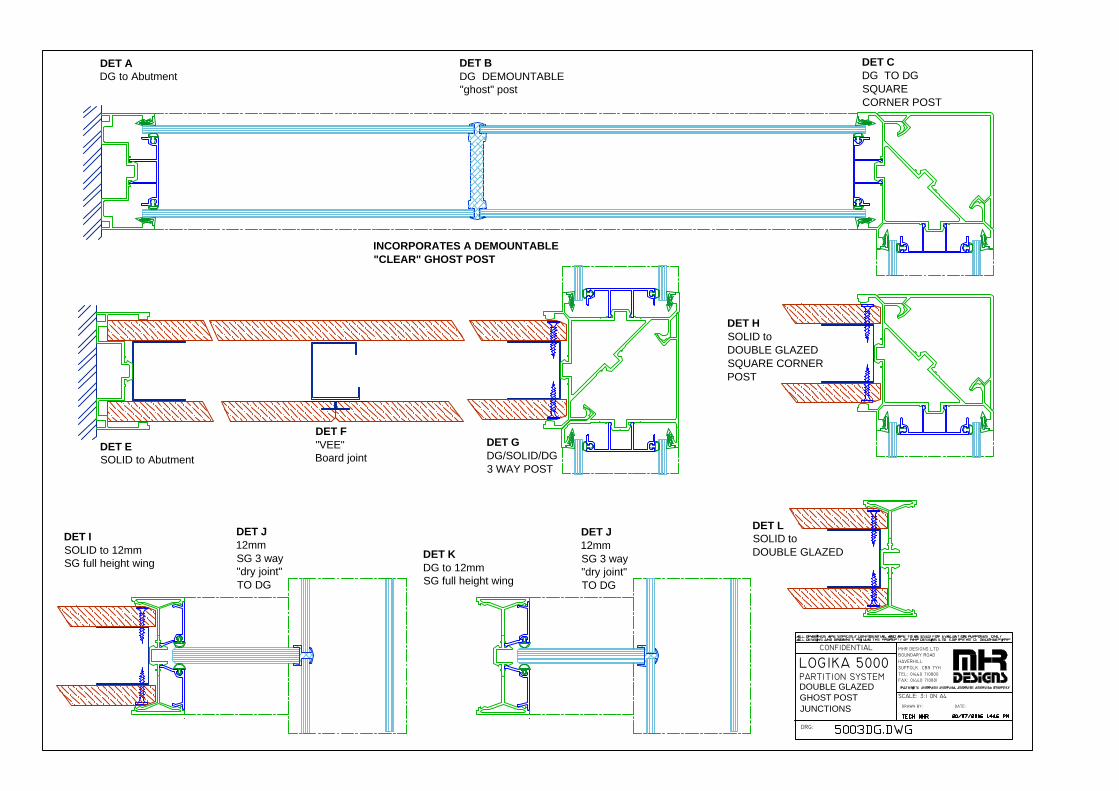
LOGIKA 5000 PARTITION SYSTEM
DRG:
CONFIDENTIAL
SUFFOLK CB9 7YH
DRAWN BY:
SCALE: 3:1 ON A4
TEL: 01440 710800FAX: 01440 710801
DATE:
HAVERHILLBOUNDARY ROADMHR DESIGNS LTD
DET ADG to Abutment
DET BDG DEMOUNTABLE"ghost" post
DET ESOLID to Abutment
DET F"VEE"Board joint
INCORPORATES A DEMOUNTABLE"CLEAR" GHOST POST
DET KDG to 12mmSG full height wing
DET CDG TO DGSQUARECORNER POST
DET GDG/SOLID/DG3 WAY POST
DET J12mmSG 3 way"dry joint"TO DG
DET ISOLID to 12mmSG full height wing
DET J12mmSG 3 way"dry joint"TO DG
DOUBLE GLAZEDGHOST POSTJUNCTIONS
DET LSOLID toDOUBLE GLAZED
DET HSOLID toDOUBLE GLAZEDSQUARE CORNERPOST

LOGIKA 5000 PARTITION SYSTEM
DRG:
CONFIDENTIAL
SUFFOLK CB9 7YH
DRAWN BY:
SCALE: 3:1 ON A4
TEL: 01440 710800FAX: 01440 710801
DATE:
HAVERHILLBOUNDARY ROADMHR DESIGNS LTD
DET BDG TO DGSQUARECORNER POSTTO GLASS DOOR(also accepts aside hung doorin glass OR timber)
DET A2 GLAZED DOORSOFF SOLID3 WAY POST(also accepts aside hung doorin glass OR timber)
DET CSOLID to GLASS DOORSQUARE CORNER POST(also accepts aside hung doorin glass OR timber)
DET DF.HT GLASS DOORto F.HT "dry joint"DOUBLE GLAZED MULLION(ONLY accepts a TOP/BOTTOMPIVOTTED door glass OR timber)
OPTIONALRADIUSSEDCORNER INFILL
OPTIONAL TIMBERDOOR PANEL
(DETAILS A,B &C ONLY)
DOUBLE GLAZEDGHOST POST SYSTEM
DOOR JUNCTIONS

LOGIKA 5000 PARTITION SYSTEM
DRG:
CONFIDENTIAL
DRAWN BY:
SCALE: 2:1 on A4
DATE:
MHR Designs LtdLogika houseHolborn AvenueMildenhallSuffolk IP28 7ANTel: 01638 583900Fax: 01638 583988FRAMELSS GLASS DOOR
IN LOGIKA 3000 ACOUSTIC FRAME

GLAZING HEAD
DETAIL AFULL HT DOUBLEGLAZING
DOOR HEAD
DETAIL BFULL HEIGHT"FRAMED"GLAZED SMOKEDOOR
DETAIL CDOUBLE GLAZEDMULLION
DETAIL DDOOR TO GLAZEDLATCH MULLION
DETAIL EWALL ABUTMENT TODOUBLE GLAZING6mm GLASS
M12
M15
M15GM23DG
G4 BACK SEAL
M23DGWEDGEG67
20/07/2006 14:51 PMTECH MHR
L5005DG-B.dwg
MHR Designs LtdLogika houseHolborn AvenueMildenhallSuffolk IP28 7ANTel: 01638 583900Fax: 01638 583988
DRAWN BY:
SCALE: 1:2 on A4
ALL DRAWINGS ARE STRICTLY CONFIDENTIAL AND ARE TO BE USED FOR EVALUATION PURPOSES ONLYALL DESIGNS AND DRAWINGS REMAIN THE PROPERTY OF MHR DESIGNS LTD. COPYRIGHT © DECEMBER 1995
DETAIL SHOWING DOUBLE GLAZING WITH ALUMINIUM FRAMED FULLY GLAZED DOORS WITH SEALED UNITS & FLOOR THRESHOLD
DRG:
CONFIDENTIAL
mhrdesigns
DATE:

LOGIKA 3000 & LOGIKA 5000 SPECIFCATIONS LOGIKA 3000 & 5000-V7B.doc 26/09/2006
MHR DESIGNS LTD. Logika House, Holborn Avenue, Mildenhall, Suffolk, IP28 7AN Tel: 01638 583900 Fax: 01638 583988
APPENDIX 2
Load Support recommendations
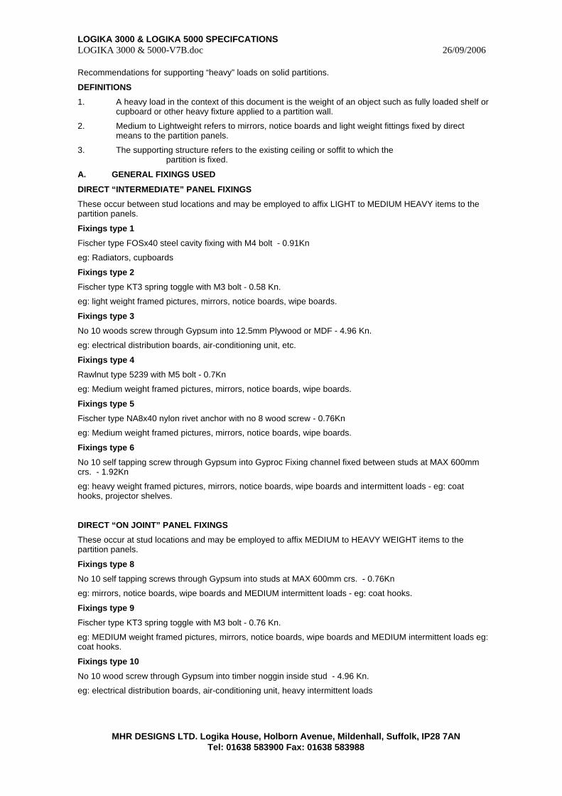
LOGIKA 3000 & LOGIKA 5000 SPECIFCATIONS LOGIKA 3000 & 5000-V7B.doc 26/09/2006
MHR DESIGNS LTD. Logika House, Holborn Avenue, Mildenhall, Suffolk, IP28 7AN Tel: 01638 583900 Fax: 01638 583988
Recommendations for supporting “heavy” loads on solid partitions.
DEFINITIONS
1. A heavy load in the context of this document is the weight of an object such as fully loaded shelf or cupboard or other heavy fixture applied to a partition wall.
2. Medium to Lightweight refers to mirrors, notice boards and light weight fittings fixed by direct means to the partition panels.
3. The supporting structure refers to the existing ceiling or soffit to which the partition is fixed.
A. GENERAL FIXINGS USED
DIRECT “INTERMEDIATE” PANEL FIXINGS
These occur between stud locations and may be employed to affix LIGHT to MEDIUM HEAVY items to the partition panels.
Fixings type 1
Fischer type FOSx40 steel cavity fixing with M4 bolt - 0.91Kn
eg: Radiators, cupboards
Fixings type 2
Fischer type KT3 spring toggle with M3 bolt - 0.58 Kn.
eg: light weight framed pictures, mirrors, notice boards, wipe boards.
Fixings type 3
No 10 woods screw through Gypsum into 12.5mm Plywood or MDF - 4.96 Kn.
eg: electrical distribution boards, air-conditioning unit, etc.
Fixings type 4
Rawlnut type 5239 with M5 bolt - 0.7Kn
eg: Medium weight framed pictures, mirrors, notice boards, wipe boards.
Fixings type 5
Fischer type NA8x40 nylon rivet anchor with no 8 wood screw - 0.76Kn
eg: Medium weight framed pictures, mirrors, notice boards, wipe boards.
Fixings type 6
No 10 self tapping screw through Gypsum into Gyproc Fixing channel fixed between studs at MAX 600mm crs. - 1.92Kn
eg: heavy weight framed pictures, mirrors, notice boards, wipe boards and intermittent loads - eg: coat hooks, projector shelves.
DIRECT “ON JOINT” PANEL FIXINGS
These occur at stud locations and may be employed to affix MEDIUM to HEAVY WEIGHT items to the partition panels.
Fixings type 8
No 10 self tapping screws through Gypsum into studs at MAX 600mm crs. - 0.76Kn
eg: mirrors, notice boards, wipe boards and MEDIUM intermittent loads - eg: coat hooks.
Fixings type 9
Fischer type KT3 spring toggle with M3 bolt - 0.76 Kn.
eg: MEDIUM weight framed pictures, mirrors, notice boards, wipe boards and MEDIUM intermittent loads eg: coat hooks.
Fixings type 10
No 10 wood screw through Gypsum into timber noggin inside stud - 4.96 Kn.
eg: electrical distribution boards, air-conditioning unit, heavy intermittent loads
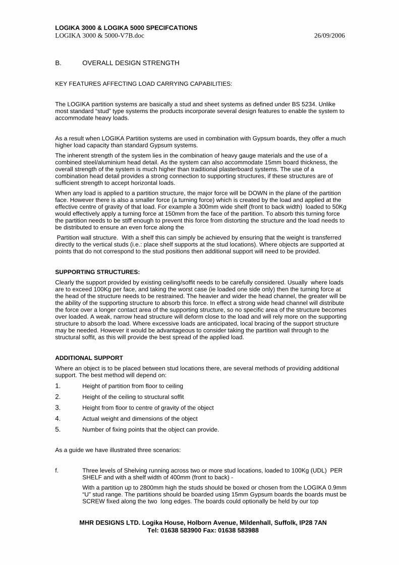
LOGIKA 3000 & LOGIKA 5000 SPECIFCATIONS LOGIKA 3000 & 5000-V7B.doc 26/09/2006
MHR DESIGNS LTD. Logika House, Holborn Avenue, Mildenhall, Suffolk, IP28 7AN Tel: 01638 583900 Fax: 01638 583988
B. OVERALL DESIGN STRENGTH
KEY FEATURES AFFECTING LOAD CARRYING CAPABILITIES:
The LOGIKA partition systems are basically a stud and sheet systems as defined under BS 5234. Unlike most standard “stud” type systems the products incorporate several design features to enable the system to accommodate heavy loads.
As a result when LOGIKA Partition systems are used in combination with Gypsum boards, they offer a much higher load capacity than standard Gypsum systems.
The inherent strength of the system lies in the combination of heavy gauge materials and the use of a combined steel/aluminium head detail. As the system can also accommodate 15mm board thickness, the overall strength of the system is much higher than traditional plasterboard systems. The use of a combination head detail provides a strong connection to supporting structures, if these structures are of sufficient strength to accept horizontal loads.
When any load is applied to a partition structure, the major force will be DOWN in the plane of the partition face. However there is also a smaller force (a turning force) which is created by the load and applied at the effective centre of gravity of that load. For example a 300mm wide shelf (front to back width) loaded to 50Kg would effectively apply a turning force at 150mm from the face of the partition. To absorb this turning force the partition needs to be stiff enough to prevent this force from distorting the structure and the load needs to be distributed to ensure an even force along the
Partition wall structure. With a shelf this can simply be achieved by ensuring that the weight is transferred directly to the vertical studs (i.e.: place shelf supports at the stud locations). Where objects are supported at points that do not correspond to the stud positions then additional support will need to be provided.
SUPPORTING STRUCTURES:
Clearly the support provided by existing ceiling/soffit needs to be carefully considered. Usually where loads are to exceed 100Kg per face, and taking the worst case (ie loaded one side only) then the turning force at the head of the structure needs to be restrained. The heavier and wider the head channel, the greater will be the ability of the supporting structure to absorb this force. In effect a strong wide head channel will distribute the force over a longer contact area of the supporting structure, so no specific area of the structure becomes over loaded. A weak, narrow head structure will deform close to the load and will rely more on the supporting structure to absorb the load. Where excessive loads are anticipated, local bracing of the support structure may be needed. However it would be advantageous to consider taking the partition wall through to the structural soffit, as this will provide the best spread of the applied load.
ADDITIONAL SUPPORT
Where an object is to be placed between stud locations there, are several methods of providing additional support. The best method will depend on:
1. Height of partition from floor to ceiling
2. Height of the ceiling to structural soffit
3. Height from floor to centre of gravity of the object
4. Actual weight and dimensions of the object
5. Number of fixing points that the object can provide.
As a guide we have illustrated three scenarios:
f. Three levels of Shelving running across two or more stud locations, loaded to 100Kg (UDL) PER SHELF and with a shelf width of 400mm (front to back) -
With a partition up to 2800mm high the studs should be boxed or chosen from the LOGIKA 0.9mm “U” stud range. The partitions should be boarded using 15mm Gypsum boards the boards must be SCREW fixed along the two long edges. The boards could optionally be held by our top
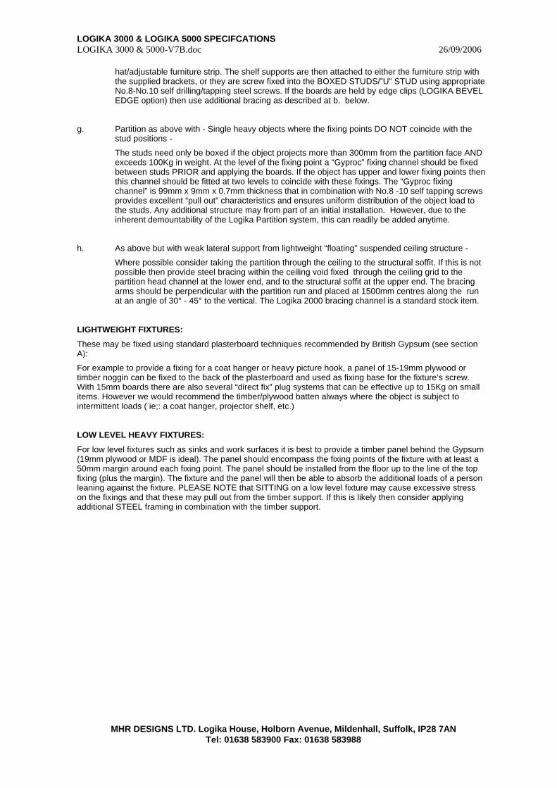
LOGIKA 3000 & LOGIKA 5000 SPECIFCATIONS LOGIKA 3000 & 5000-V7B.doc 26/09/2006
MHR DESIGNS LTD. Logika House, Holborn Avenue, Mildenhall, Suffolk, IP28 7AN Tel: 01638 583900 Fax: 01638 583988
hat/adjustable furniture strip. The shelf supports are then attached to either the furniture strip with the supplied brackets, or they are screw fixed into the BOXED STUDS/”U” STUD using appropriate No.8-No.10 self drilling/tapping steel screws. If the boards are held by edge clips (LOGIKA BEVEL EDGE option) then use additional bracing as described at b. below.
g. Partition as above with - Single heavy objects where the fixing points DO NOT coincide with the stud positions -
The studs need only be boxed if the object projects more than 300mm from the partition face AND exceeds 100Kg in weight. At the level of the fixing point a “Gyproc” fixing channel should be fixed between studs PRIOR and applying the boards. If the object has upper and lower fixing points then this channel should be fitted at two levels to coincide with these fixings. The “Gyproc fixing channel” is 99mm x 9mm x 0.7mm thickness that in combination with No.8 -10 self tapping screws provides excellent “pull out” characteristics and ensures uniform distribution of the object load to the studs. Any additional structure may from part of an initial installation. However, due to the inherent demountability of the Logika Partition system, this can readily be added anytime.
h. As above but with weak lateral support from lightweight “floating” suspended ceiling structure -
Where possible consider taking the partition through the ceiling to the structural soffit. If this is not possible then provide steel bracing within the ceiling void fixed through the ceiling grid to the partition head channel at the lower end, and to the structural soffit at the upper end. The bracing arms should be perpendicular with the partition run and placed at 1500mm centres along the run at an angle of 30° - 45° to the vertical. The Logika 2000 bracing channel is a standard stock item.
LIGHTWEIGHT FIXTURES:
These may be fixed using standard plasterboard techniques recommended by British Gypsum (see section A):
For example to provide a fixing for a coat hanger or heavy picture hook, a panel of 15-19mm plywood or timber noggin can be fixed to the back of the plasterboard and used as fixing base for the fixture’s screw. With 15mm boards there are also several “direct fix” plug systems that can be effective up to 15Kg on small items. However we would recommend the timber/plywood batten always where the object is subject to intermittent loads ( ie;: a coat hanger, projector shelf, etc.)
LOW LEVEL HEAVY FIXTURES:
For low level fixtures such as sinks and work surfaces it is best to provide a timber panel behind the Gypsum (19mm plywood or MDF is ideal). The panel should encompass the fixing points of the fixture with at least a 50mm margin around each fixing point. The panel should be installed from the floor up to the line of the top fixing (plus the margin). The fixture and the panel will then be able to absorb the additional loads of a person leaning against the fixture. PLEASE NOTE that SITTING on a low level fixture may cause excessive stress on the fixings and that these may pull out from the timber support. If this is likely then consider applying additional STEEL framing in combination with the timber support.
LOGIKA 3000 & LOGIKA 5000 SPECIFCATIONS LOGIKA 3000 & 5000-V7B.doc 26/09/2006
MHR DESIGNS LTD. Logika House, Holborn Avenue, Mildenhall, Suffolk, IP28 7AN Tel: 01638 583900 Fax: 01638 583988
APPENDIX 3
Summary Acoustic
& FIRE Tests
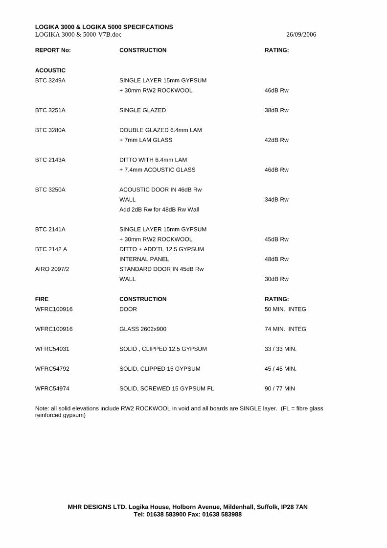
LOGIKA 3000 & LOGIKA 5000 SPECIFCATIONS LOGIKA 3000 & 5000-V7B.doc 26/09/2006
MHR DESIGNS LTD. Logika House, Holborn Avenue, Mildenhall, Suffolk, IP28 7AN Tel: 01638 583900 Fax: 01638 583988
REPORT No: CONSTRUCTION RATING:
ACOUSTIC
BTC 3249A SINGLE LAYER 15mm GYPSUM
+ 30mm RW2 ROCKWOOL 46dB Rw
BTC 3251A SINGLE GLAZED 38dB Rw
BTC 3280A DOUBLE GLAZED 6.4mm LAM
+ 7mm LAM GLASS 42dB Rw
BTC 2143A DITTO WITH 6.4mm LAM
+ 7.4mm ACOUSTIC GLASS 46dB Rw
BTC 3250A ACOUSTIC DOOR IN 46dB Rw
WALL 34dB Rw
Add 2dB Rw for 48dB Rw Wall
BTC 2141A SINGLE LAYER 15mm GYPSUM
+ 30mm RW2 ROCKWOOL 45dB Rw
BTC 2142 A DITTO + ADD’TL 12.5 GYPSUM
INTERNAL PANEL 48dB Rw
AIRO 2097/2 STANDARD DOOR IN 45dB Rw
WALL 30dB Rw
FIRE CONSTRUCTION RATING:
WFRC100916 DOOR 50 MIN. INTEG
WFRC100916 GLASS 2602x900 74 MIN. INTEG
WFRC54031 SOLID , CLIPPED 12.5 GYPSUM 33 / 33 MIN.
WFRC54792 SOLID, CLIPPED 15 GYPSUM 45 / 45 MIN.
WFRC54974 SOLID, SCREWED 15 GYPSUM FL 90 / 77 MIN
Note: all solid elevations include RW2 ROCKWOOL in void and all boards are SINGLE layer. (FL = fibre glass reinforced gypsum)

LOGIKA 3000 & LOGIKA 5000 SPECIFCATIONS LOGIKA 3000 & 5000-V7B.doc 26/09/2006
MHR DESIGNS LTD. Logika House, Holborn Avenue, Mildenhall, Suffolk, IP28 7AN Tel: 01638 583900 Fax: 01638 583988
APPENDIX 4
PROJECT SPECIFIC
DETAILS

LOGIKA 3000 & LOGIKA 5000 SPECIFCATIONS LOGIKA 3000 & 5000-V7B.doc 26/09/2006
MHR DESIGNS LTD. Logika House, Holborn Avenue, Mildenhall, Suffolk, IP28 7AN Tel: 01638 583900 Fax: 01638 583988
INDEX TO PROJECT SPECIFIC DETAILS
TO BE READ IN CONJUCTION WITH
LOGIKA 3000 & 5000 SPECIFICATION & TECHNICAL MANUAL
DRAWINGS
DOCUMENTS
LOGIKA 3000 & LOGIKA 5000 SPECIFCATIONS LOGIKA 3000 & 5000-V7B.doc 26/09/2006
MHR DESIGNS LTD. Logika House, Holborn Avenue, Mildenhall, Suffolk, IP28 7AN Tel: 01638 583900 Fax: 01638 583988
APPENDIX 4A
Project specific
CALCULATIONS
(Where applicable)
LOGIKA 3000 & LOGIKA 5000 SPECIFCATIONS LOGIKA 3000 & 5000-V7B.doc 26/09/2006
MHR DESIGNS LTD. Logika House, Holborn Avenue, Mildenhall, Suffolk, IP28 7AN Tel: 01638 583900 Fax: 01638 583988
APPENDIX 5
Installation Sequence & Training
LOGIKA 3000 & LOGIKA 5000 SPECIFCATIONS LOGIKA 3000 & 5000-V7B.doc 26/09/2006
MHR DESIGNS LTD. Logika House, Holborn Avenue, Mildenhall Suffolk, IP28 7AN
Tel: 01638 583900 Fax: 01638 583988
FOREWORD
PRODUCT LIABILITY
SKILL and STANDARDS:
LOGIKA 3000/5000 is a bespoke high performance partition system which is only installed by personnel who are skilled in the working of all materials used in the product and have a working knowledge of partition installation. Installers must be provided with the correct tools and safety equipment. The Installing Sub Contractors Site Supervisor will have ultimate responsibility for safety and ensuring that all foremen and supervisors of installers have as a minimum requirement a working knowledge of the relevant sections of:
BS5234 Part 1
BS6262
BS8233
BS6206
BS8212
BS8000
BS6180
And ALL related British Standards and codes of Practice
In addition due regard must be made to ensure compliance with
Building Regulations and local regulations together with the relevant regulations regarding lifting and manual handling.
DISCLAIMER:
MHR Designs Ltd. will not accept liability for site performance or any breach of the above standards or regulations when the product is installed, modified or dismantled by any person or organisation that has not been appointed as an APPROVED CONTRACTOR or has not satisfied the company that they are skilled in the installation of the product. All installers should be supervised by personnel who have a full appraisal of the relevant standards and regulations including HSE.
PRODUCT TRAINING:
Product training assumes that personnel are professional installers skilled in the installation of partition systems and only covers specific details directly related to the installation of Logika products
Logika 3000 / 5000 Product training does not cover the basic skills required for the processing of aluminium, steel and PVC products or those related to the handling of Gypsum and mineral fibre product. It is recommended that all installers of our products have attended a training seminar at MHR.
The following installation information is not intended as a definitive method of installation for our products and may be adapted to suit the particular requirements of The Installing Sub Contractors fixing team or to suit particular site requirements specific to the project. For experienced partition installers it will be inevitable that they will have their own preferred way of installing our products and whist this may not concur in all aspects with the following recommendations it is essential that The Installing Sub Contractor ensures that the final installed product complies with the recommendations given in this manual and that performance of the product is not compromised through poor installation. It is The Installing Sub Contractors responsibility to ensure that the product performance is not compromised by poor installation or by exceeding the limitations of the system as detailed in this manual.

LOGIKA 3000 & LOGIKA 5000 SPECIFCATIONS LOGIKA 3000 & 5000-V7B.doc 26/09/2006
MHR DESIGNS LTD. Logika House, Holborn Avenue, Mildenhall
Suffolk, IP28 7AN Tel: 01638 583900 Fax: 01638 583988
1.0 INSTALLATION:
1.1 GENERAL REQUIREMENTS:
1.2 To be read in conjunction with Method Statements in APPENIX 6F & 6G
The quality of any partition installation is directly influenced by the quality of cut and neatness of the joints between adjacent profiles. It is assumed that the installer is familiar with aluminium cutting and has the appropriate tools for the accurate measuring, cutting and installation of the materials used in LOGIKA 3000. To assist the installer, the design has reduced the number of VISIBLE joints to a minimum, by ensuring that all secondary profiles to fit WITHIN the PRIMARY section. This also means that setting out is simplified as no allowance is needed for adding these components.
To ensure a good quality of cut on VISIBLE joints, it is recommended that a portable aluminium site saw is used. From trials with various models, the ELU TGS176 is probably the most versatile and provides an excellent finish, although a Makita and De-Walt models are also available. It is essential that the saw is cutting true and the blade is sharp if an acceptable joint between profiles is to be achieved. In addition to aluminium cutting saw the following tools are essential for the installation of LOGIKA 3000.
1.3 TOOLS & EQUIPMENT:
Steel engineers square, water level, long spirit level, measuring rods, accurate tape measure, chalk line, plumb line, electric screwdriver gun with POZI bits, electric drill (including switchable hammer action) with 3000m and 3.5mm high speed drill bits, 6mm masonry bit, mastic gun, clamps, router, pop-rivet gun, hacksaw, flat file, steel cutters, chisels, plane, board saw, retractable knife, lambswool roller, bucket, full set of taping and jointing tools, adjustable supports for saw, steps, clip insertion tool, router jigs, spare chalk, safety hat, goggles, protective clothing, gloves, cleaning materials, cloths, brush, masking tape, oil stone, spiral ratchet screwdriver (Yankee), spare screws and rivets, hammer, flat knife, 13mm cold chisel, 50mm cold chisel, board lifter, seam roller, glass lifters (2 No.), workmate, wire wool, wood filler, polish, resin "W" adhesive, wall covering paste, site lighting (if required), transformers, ll0V extension leads, spare batteries and charger, steps, scaffolding, access tower.
The above list is by no means exhaustive and will depend on the installers own requirements and the partition type being installed
Refer to Drawings in Appendix 1 Section A for Logika 3000 and sections 2 - 8 and 10 - 11 below
Refer to Drawings in Appendix 1 Sections B and C for Logika 5000 and section 9 below.
2 LOGIKA 3000
2.1 SETTING OUT – APPLIES TO BOTH NON-FIRE RATED AND FIRE RATED CONSTRUCTIONS
A. Mark out runs
Mark positions of partition runs on the floor using the centre line of the walls.
Mark the position of junctions, end posts and doorways.
TIP When setting out junctions, it is useful to use small off cuts of sections as guides/templates. (Note: all sections are 50mm oversize to allow for trimming so the offcut generated can be used for setting out).
B. Mark out Abutments
Plumb down abutment positions on existing walls and check for obstructions.
C. Useful Dimensions:
M110 SINGLE DOOR FRAME OPENING (M11 post to M11 post Ali face to Ali face) = DOOR WIDTH + 12mm.
M110 DOUBLE DOOR FRAME OPENING (Ali face to Ali face) = DOOR WIDTH + 15mm.
TIP: Use 100mm wide timber batten, square cut to door opening size to aid setting out.
NOTE: The M110 Door frame adds 6mm in addition to the clearances added to the door width. ie: adds 12mm.
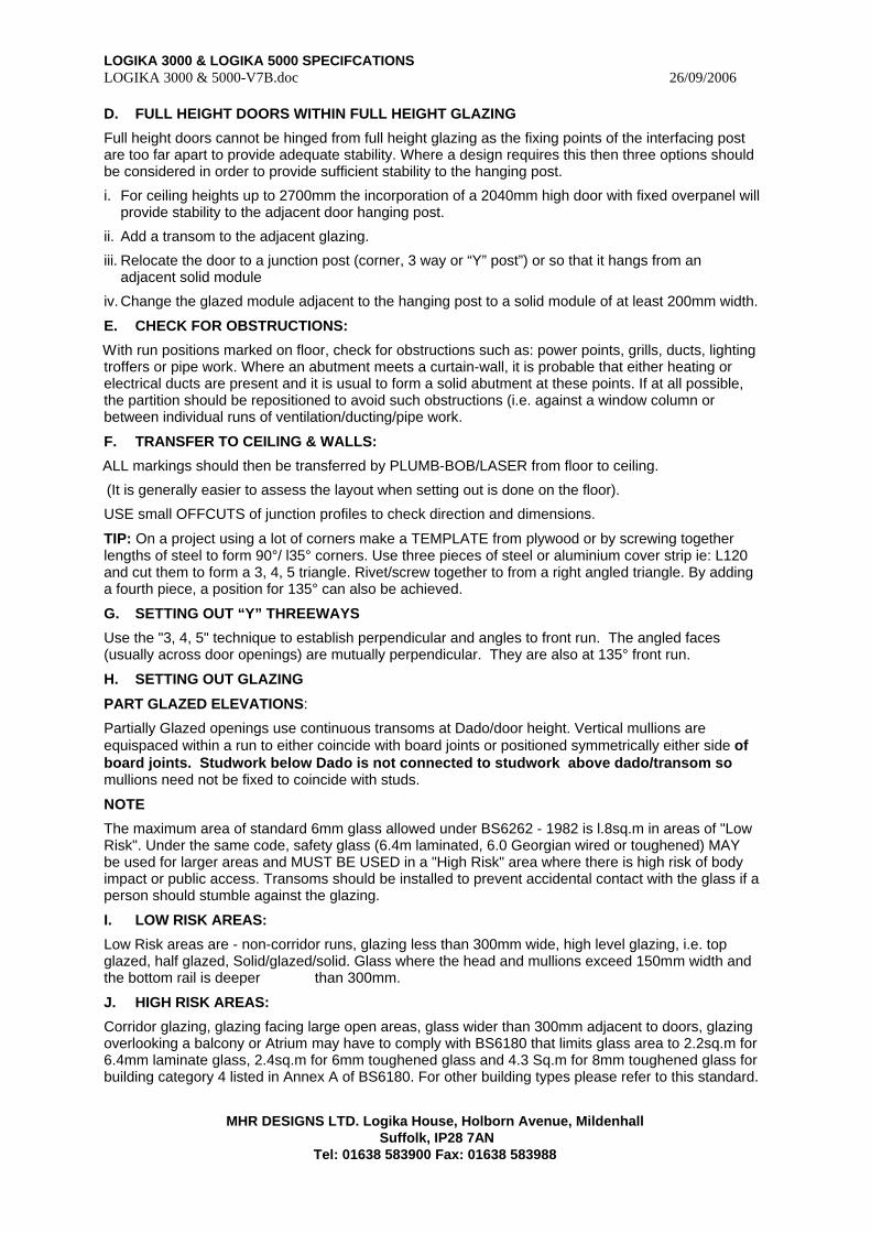
LOGIKA 3000 & LOGIKA 5000 SPECIFCATIONS LOGIKA 3000 & 5000-V7B.doc 26/09/2006
MHR DESIGNS LTD. Logika House, Holborn Avenue, Mildenhall
Suffolk, IP28 7AN Tel: 01638 583900 Fax: 01638 583988
D. FULL HEIGHT DOORS WITHIN FULL HEIGHT GLAZING
Full height doors cannot be hinged from full height glazing as the fixing points of the interfacing post are too far apart to provide adequate stability. Where a design requires this then three options should be considered in order to provide sufficient stability to the hanging post.
i. For ceiling heights up to 2700mm the incorporation of a 2040mm high door with fixed overpanel will provide stability to the adjacent door hanging post.
ii. Add a transom to the adjacent glazing.
iii. Relocate the door to a junction post (corner, 3 way or “Y” post”) or so that it hangs from an adjacent solid module
iv. Change the glazed module adjacent to the hanging post to a solid module of at least 200mm width.
E. CHECK FOR OBSTRUCTIONS:
With run positions marked on floor, check for obstructions such as: power points, grills, ducts, lighting troffers or pipe work. Where an abutment meets a curtain-wall, it is probable that either heating or electrical ducts are present and it is usual to form a solid abutment at these points. If at all possible, the partition should be repositioned to avoid such obstructions (i.e. against a window column or between individual runs of ventilation/ducting/pipe work.
F. TRANSFER TO CEILING & WALLS:
ALL markings should then be transferred by PLUMB-BOB/LASER from floor to ceiling.
(It is generally easier to assess the layout when setting out is done on the floor).
USE small OFFCUTS of junction profiles to check direction and dimensions.
TIP: On a project using a lot of corners make a TEMPLATE from plywood or by screwing together lengths of steel to form 90°/ l35° corners. Use three pieces of steel or aluminium cover strip ie: L120 and cut them to form a 3, 4, 5 triangle. Rivet/screw together to from a right angled triangle. By adding a fourth piece, a position for 135° can also be achieved.
G. SETTING OUT “Y” THREEWAYS
Use the "3, 4, 5" technique to establish perpendicular and angles to front run. The angled faces (usually across door openings) are mutually perpendicular. They are also at 135° front run.
H. SETTING OUT GLAZING
PART GLAZED ELEVATIONS:
Partially Glazed openings use continuous transoms at Dado/door height. Vertical mullions are equispaced within a run to either coincide with board joints or positioned symmetrically either side of board joints. Studwork below Dado is not connected to studwork above dado/transom so mullions need not be fixed to coincide with studs.
NOTE
The maximum area of standard 6mm glass allowed under BS6262 - 1982 is l.8sq.m in areas of "Low Risk". Under the same code, safety glass (6.4m laminated, 6.0 Georgian wired or toughened) MAY be used for larger areas and MUST BE USED in a "High Risk" area where there is high risk of body impact or public access. Transoms should be installed to prevent accidental contact with the glass if a person should stumble against the glazing.
I. LOW RISK AREAS:
Low Risk areas are - non-corridor runs, glazing less than 300mm wide, high level glazing, i.e. top glazed, half glazed, Solid/glazed/solid. Glass where the head and mullions exceed 150mm width and the bottom rail is deeper than 300mm.
J. HIGH RISK AREAS:
Corridor glazing, glazing facing large open areas, glass wider than 300mm adjacent to doors, glazing overlooking a balcony or Atrium may have to comply with BS6180 that limits glass area to 2.2sq.m for 6.4mm laminate glass, 2.4sq.m for 6mm toughened glass and 4.3 Sq.m for 8mm toughened glass for building category 4 listed in Annex A of BS6180. For other building types please refer to this standard.
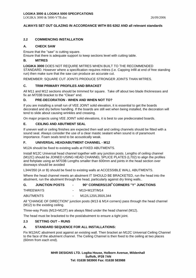
LOGIKA 3000 & LOGIKA 5000 SPECIFCATIONS LOGIKA 3000 & 5000-V7B.doc 26/09/2006
MHR DESIGNS LTD. Logika House, Holborn Avenue, Mildenhall
Suffolk, IP28 7AN Tel: 01638 583900 Fax: 01638 583988
ALWAYS SET OUT GLAZING IN ACCORDANCE WITH BS 6262 AND all relevant standards
2.2 COMMENCING INSTALLATION
A. CHECK SAW
Ensure that the "saw" is cutting square. Ensure that there is adequate support to keep sections level with cutting table. B. MITRES
LOGIKA 3000 DOES NOT REQUIRE MITRES WHEN BUILT TO THE RECOMMENDED STANDARD. However where a specification requires mitres (i.e. Capping Infill at end of free standing run) then make sure that the saw can produce an accurate cut.
REMEMBER: SQUARE CUT JOINTS PRODUCE STRONGER JOINTS THAN MITRES.
C. TRIM PRIMARY PROFILES AND BRACKET
All M11 and M12 sections should be trimmed for square. Take off about two blade thicknesses and fix an M703B bracket to the “Clean” end. D. PRE-DECORATION - WHEN AND WHEN NOT TO?
If you are installing a small run of VEE JOINT solid elevation, it is essential to get the boards decorated and dry before handling. If the boards are still wet when being installed, the decoration will tend to slide about causing wrinkles and creasing.
On major projects using VEE JOINT solid elevations, it is best to use predecorated boards.
E. CEILING AND ABUTMENT SEAL
If uneven wall or ceiling finishes are expected then wall and ceiling channels should be fitted with a sound seal. Always consider the use of a clear mastic sealant when sound is of paramount importance. Foam seals tend to be acoustically weak.
F. UNIVERSAL HEAD/ABUTMENT CHANNEL - M12
M12A should be fixed to existing walls at FIXED ABUTMENTS.
Install M12C Universal head channel together with any junction posts. Lengths of ceiling channel (M12C) should be JOINED USING HEAD CHANNEL SPLICE PLATES (L702) to align the profiles and fishplate using an M703B Lengths smaller than 600mm and joints in the head section over doorways should be avoided
L344/350 (A or B) should be fixed to existing walls at ACCESSIBLE WALL ABUTMENTS.
Where the head channel meets an abutment IT SHOULD BE BRACKETED, run the head into the abutment, run the abutment through the head, particularly against dry lining walls..
G. JUNCTION POSTS - 90° CORNERS/1350 CORNERS "Y" JUNCTIONS
THREEWAYS - M13+M13T/M14
ABUTMENTS - M12/L120/L350/L344
All "CHANGE OF DIRECTION" junction posts (M13 & M14 corners) pass through the head channel (M12) to the existing ceiling.
Three-way Posts (M13+M13T) are always fitted under the head channel (M12).
The head must be bracketed to the post/abutment to ensure a tight joint.
2.3 SETTING OUT – RUNS
A. STANDARD SEQUENCE FOR ALL INSTALLATIONS:
Fix M12A/C abutment post against an existing wall. Then bracket an M12C Universal Ceiling Channel to the face of the abutment channel. The Ceiling Channel is then fixed to the ceiling at two places (60mm from each end).
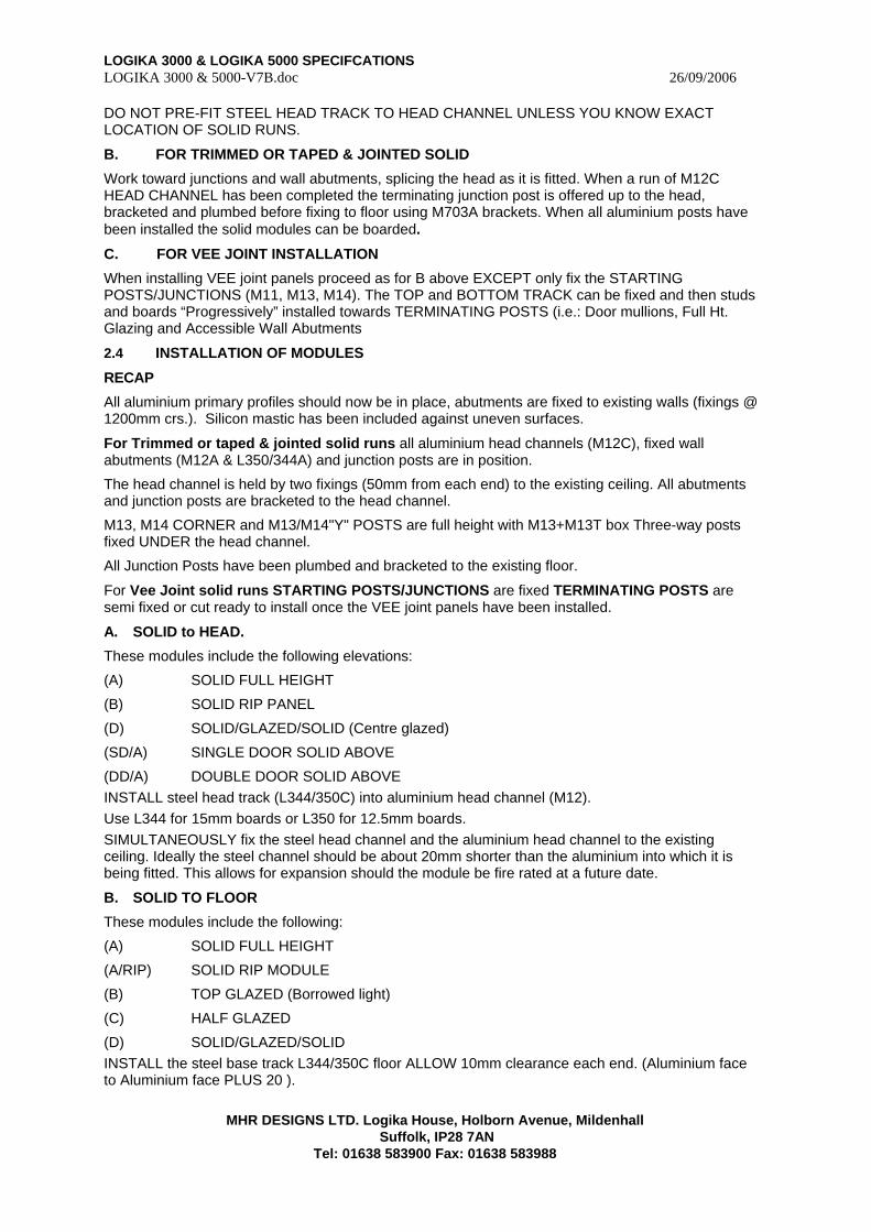
LOGIKA 3000 & LOGIKA 5000 SPECIFCATIONS LOGIKA 3000 & 5000-V7B.doc 26/09/2006
MHR DESIGNS LTD. Logika House, Holborn Avenue, Mildenhall
Suffolk, IP28 7AN Tel: 01638 583900 Fax: 01638 583988
DO NOT PRE-FIT STEEL HEAD TRACK TO HEAD CHANNEL UNLESS YOU KNOW EXACT LOCATION OF SOLID RUNS.
B. FOR TRIMMED OR TAPED & JOINTED SOLID
Work toward junctions and wall abutments, splicing the head as it is fitted. When a run of M12C HEAD CHANNEL has been completed the terminating junction post is offered up to the head, bracketed and plumbed before fixing to floor using M703A brackets. When all aluminium posts have been installed the solid modules can be boarded.
C. FOR VEE JOINT INSTALLATION
When installing VEE joint panels proceed as for B above EXCEPT only fix the STARTING POSTS/JUNCTIONS (M11, M13, M14). The TOP and BOTTOM TRACK can be fixed and then studs and boards “Progressively” installed towards TERMINATING POSTS (i.e.: Door mullions, Full Ht. Glazing and Accessible Wall Abutments
2.4 INSTALLATION OF MODULES
RECAP
All aluminium primary profiles should now be in place, abutments are fixed to existing walls (fixings @ 1200mm crs.). Silicon mastic has been included against uneven surfaces.
For Trimmed or taped & jointed solid runs all aluminium head channels (M12C), fixed wall abutments (M12A & L350/344A) and junction posts are in position.
The head channel is held by two fixings (50mm from each end) to the existing ceiling. All abutments and junction posts are bracketed to the head channel.
M13, M14 CORNER and M13/M14"Y" POSTS are full height with M13+M13T box Three-way posts fixed UNDER the head channel.
All Junction Posts have been plumbed and bracketed to the existing floor.
For Vee Joint solid runs STARTING POSTS/JUNCTIONS are fixed TERMINATING POSTS are semi fixed or cut ready to install once the VEE joint panels have been installed.
A. SOLID to HEAD.
These modules include the following elevations:
(A) SOLID FULL HEIGHT
(B) SOLID RIP PANEL
(D) SOLID/GLAZED/SOLID (Centre glazed)
(SD/A) SINGLE DOOR SOLID ABOVE
(DD/A) DOUBLE DOOR SOLID ABOVE INSTALL steel head track (L344/350C) into aluminium head channel (M12). Use L344 for 15mm boards or L350 for 12.5mm boards. SIMULTANEOUSLY fix the steel head channel and the aluminium head channel to the existing ceiling. Ideally the steel channel should be about 20mm shorter than the aluminium into which it is being fitted. This allows for expansion should the module be fire rated at a future date.
B. SOLID TO FLOOR
These modules include the following:
(A) SOLID FULL HEIGHT
(A/RIP) SOLID RIP MODULE
(B) TOP GLAZED (Borrowed light)
(C) HALF GLAZED
(D) SOLID/GLAZED/SOLID INSTALL the steel base track L344/350C floor ALLOW 10mm clearance each end. (Aluminium face to Aluminium face PLUS 20 ).
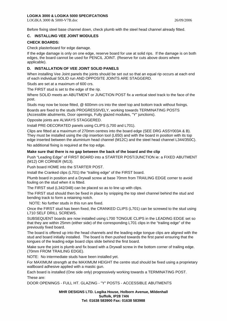
LOGIKA 3000 & LOGIKA 5000 SPECIFCATIONS LOGIKA 3000 & 5000-V7B.doc 26/09/2006
MHR DESIGNS LTD. Logika House, Holborn Avenue, Mildenhall
Suffolk, IP28 7AN Tel: 01638 583900 Fax: 01638 583988
Before fixing steel base channel down, check plumb with the steel head channel already fitted.
C. INSTALLING VEE JOINT MODULES
CHECK BOARDS: Check plasterboard for edge damage. If the edge damage is only on one edge, reserve board for use at solid rips. If the damage is on both edges, the board cannot be used for PENCIL JOINT. (Reserve for cuts above doors where applicable).
D. INSTALLATION OF VEE JOINT SOLID PANELS When installing Vee Joint panels the joints should be set out so that an equal rip occurs at each end of each individual SOLID run AND OPPOSITE JOINTS ARE STAGGERD. Studs are set at a maximum of 600 crs. The FIRST stud is set to the edge of the rip. Where SOLID meets an ABUTMENT or JUNCTION POST fix a vertical steel track to the face of the post. Studs may now be loose fitted, @ 600mm crs into the steel top and bottom track without fixings. Boards are fixed to the studs PROGRESSIVELY, working towards TERMINATING POSTS (Accessible abutments, Door openings, Fully glazed modules, "Y" junctions). Opposite joints are ALWAYS STAGGERED. Install PRE-DECORATED panels using CLIPS (L700 and L701). Clips are fitted at a maximum of 270mm centres into the board edge (SEE DRG ASSY003A & B). They must be installed using the clip insertion tool (L650) and with the board in position with its top edge inserted between the aluminium head channel (M12C) and the steel head channel L344/350C). No additional fixing is required at the top edge.
Make sure that there is no gap between the back of the board and the clip Push “Leading Edge” of FIRST BOARD into a STARTER POST/JUNCTION ie: a FIXED ABUTMENT (M12) OR CORNER (M13). Push board HOME into the STARTER POST. Install the Cranked clips (L701) the “trailing edge” of the FIRST board. Plumb board in position and a Drywall screw at base 70mm from TRAILING EDGE corner to avoid fouling on the stud when it is fitted. The FIRST stud (L342/348) can be placed so as to line up with clips. The FIRST stud should then be fixed in place by snipping the top steel channel behind the stud and bending track to form a retaining notch. NOTE: No further studs in this run are fixed. Once the FIRST stud has been fixed, the CRANKED CLIPS (L701) can be screwed to the stud using L710 SELF DRILL SCREWS. SUBSEQUENT boards are now installed using L700 TONGUE CLIPS in the LEADING EDGE set so that they are within 25mm (either side) of the corresponding L701 clips in the “trailing edge” of the previously fixed board. The board is offered up into the head channels and the leading edge tongue clips are aligned with the stud and board initially installed. The board is then pushed towards the first panel ensuring that the tongues of the leading edge board clips slide behind the first board. Make sure the joint is plumb and fix board with a Drywall screw in the bottom corner of trailing edge. (70mm FROM TRAILING EDGE). NOTE: No intermediate studs have been installed yet. For MAXIMUM strength at the MAXIMUM HEIGHT the centre stud should be fixed using a proprietary wallboard adhesive applied with a mastic gun. Each board is installed (One side only) progressively working towards a TERMINATING POST. These are: DOOR OPENINGS - FULL HT. GLAZING - "Y" POSTS - ACCESSIBLE ABUTMENTS
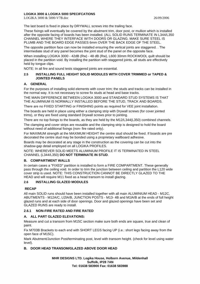
LOGIKA 3000 & LOGIKA 5000 SPECIFCATIONS LOGIKA 3000 & 5000-V7B.doc 26/09/2006
MHR DESIGNS LTD. Logika House, Holborn Avenue, Mildenhall
Suffolk, IP28 7AN Tel: 01638 583900 Fax: 01638 583988
The last board is fixed in place by DRYWALL screws into the trailing face. These fixings will eventually be covered by the abutment trim, door post, or mullion which is installed after the opposite facing of boards has been installed. (ALL SOLID RUNS TERMINATE IN L344/L350 CHANNEL WHERE THEY INTERFACE WITH DOORS OR GLAZING. MAKE SURE STEEL IS PLUMB AND THE BOARD EDGE PASSES 6mm OVER THE BACK EDGE OF THE STEEL. The opposite partition face can now be installed ensuring the vertical joints are staggered. . The intermediate stud of any panel becomes the joint stud of the panel on the opposite face. When installing LOGIKA 3000 - 42dB (Rw) - 48 dB (Rw), L600 30mm ROCKWOOL quilt should be placed in the partition void. By installing the partition with staggered joints, all studs are effectively held by tongue clips. NOTE: In all fire and sound tests staggered joints are essential.
2.5 INSTALLING FULL HEIGHT SOLID MODULES WITH COVER TRIMMED or TAPED & JOINTED PANELS
A. GENERAL For the purposes of installing solid elements with cover trim; the studs and tracks can be installed in the normal way. It is not necessary to screw fix studs at head and base tracks. THE MAIN DIFFERENCE BETWEEN LOGIKA 3000 and STANDARD STUD SYSTEMS IS THAT THE ALUMINIUM IS NORMALLY INSTALLED BEFORE THE STUD, TRACK AND BOARDS. There are no FIXED STARTING or FINISHING points as required for VEE joint installation. The boards are held in place using either a clamping strip with Drywall screws (for cover jointed trims), or they are fixed using standard Drywall screws prior to jointing. There are no top fixings to the boards, as they are held by the M12/L344(L350) combined channels. The clamping and cover strips are reusable and the clamping strip is designed to hold the board without need of additional fixings (non- fire rated only). For MAXIMUM strength at the MAXIMUM HEIGHT the centre stud should be fixed. If boards are pre decorated the centre stud may be bonded using a proprietary wallboard adhesive. Boards may be decorated at any stage in the construction as the covering can be cut into the shadow-gap detail employed on all LOGIKA PROFILES. NOTE: WHEREVER SOLID MEETS ALUMINIUM PROFILE IT IS TERMINATED IN STEEL CHANNEL (L344/L350) DO NOT TERMINATE IN STUD.
B. COMPARTMENT WALLS In certain cases a "FIXED" partition is installed to form a FIRE COMPARTMENT. These generally pass through the ceiling void. In order to trim the junction between ceiling and partition the L120 wide cover strip is used. NOTE: THIS CONSTRUCTION CANNOT BE DIRECTLY GLAZED TO THE HEAD and will require M11 fixed as a head transom to install glazing. 2.6 INSTALLING GLAZED MODULES
RECAP All main SOLID runs should have been installed together with all main ALUMINIUM HEAD - M12C, ABUTMENTS - M12A/C, Ll2lA/B, JUNCTION POSTS - M13- 4B and M1lA/B at the ends of full height glazed runs and at each side of door openings. Door and glazed openings have been set and GLAZED RUNS are ready to install.
2.6.1 NON-FIRE RATED AND FIRE RATED
A. ALL PART GLAZED ELEVATIONS: Measure and cut a transom from M15C section make sure both ends are square, true and clean of paint. Fix M703B Brackets to each end with SHORT LEGS facing UP (i.e.: short legs facing away from the open face of M15C). Mark Abutment/Junction Post/terminating post, level with transom height. (check for level using water level).
B. DOOR HEAD TRANSOM/GLAZED ABOVE DOOR HEAD
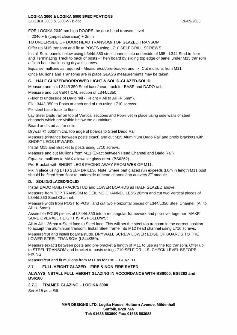
LOGIKA 3000 & LOGIKA 5000 SPECIFCATIONS LOGIKA 3000 & 5000-V7B.doc 26/09/2006
MHR DESIGNS LTD. Logika House, Holborn Avenue, Mildenhall
Suffolk, IP28 7AN Tel: 01638 583900 Fax: 01638 583988
FOR LOGIKA 2040mm high DOORS the door head transom level = 2040 + 5 (carpet clearance) + 2mm TO UNDERSIDE OF DOOR HEAD TRANSOM/ TOP GLAZED TRANSOM. Offer up M15 transom and fix to POSTS using L710 SELF DRILL SCREWS Install Solid panels below using L344/L350 steel channel into underside of Ml5 - L344 Stud to floor and Terminating Track to back of posts - Then board by sliding top edge of panel under M15 transom a fix to base track using drywall screws. Equalise mullions as required - Measure/cut/pre-bracket and fix. Cut mullions from M11. Once Mullions and Transoms are in place GLASS measurements may be taken.
C. HALF GLAZED/BORROWED LIGHT & SOLID-GLAZED-SOLID Measure and cut L344/L350 Steel base/head track for BASE and DADO rail. Measure and cut VERTICAL section of L344/L350 (Floor to underside of Dado rail - Height = Ali to Ali +/- 5mm). Fix L344/L350 to Posts at each end of run using L710 screws. Fix steel base track to floor. Lay Steel Dado rail on top of Vertical sections and Pop-rivet in place using side walls of steel channels which are visible below the aluminium. Board and stud as for solid. Drywall @ 600mm crs. top edge of boards to Steel Dado Rail. Measure (distance between posts exact) and cut M15 Aluminium Dado Rail and prefix brackets with SHORT LEGS UPWARD. Install M15 and Bracket to posts using L710 screws. Measure and cut Mullions from M11 (Exact between Head Channel and Dado Rail). Equalise mullions to MAX allowable glass area. (BS6262). Pre-Bracket with SHORT LEGS FACING AWAY FROM WEB OF M11. Fix in place using L710 SELF DRILLS. Note: where part glazed run exceeds 3.6m in length M11 post should be fitted from floor to underside of head channel/top at every 3rd module.
D. SOLID/GLAZED/SOLID Install DADO RAIL/TRACK/STUD and LOWER BOARDS as HALF GLAZED above. Measure from TOP TRANSOM to CEILING CHANNEL LESS 26mm and cut two Vertical pieces of L344/L350 Steel Channel. Measure width from POST to POST and cut two Horizontal pieces of L344/L350 Steel Channel. (Ali to Ali +/- 5mm) Assemble FOUR pieces of L344/L350 into a rectangular framework and pop-rivet together. MAKE SURE OVERALL HEIGHT IS AS FOLLOWS: Ali to Ali + 26mm = Steel face to Steel face. This will set the steel top transom in the correct position to accept the aluminium transom. Install Steel frame into M12 head channel using L710 screws. Measure/cut and install boards/studs. DRYWALL SCREW LOWER EDGE OF BOARDS TO THE LOWER STEEL TRANSOM (L344/350).
Measure (exact) between posts and pre-bracket a length of M11 to use as the top transom. Offer up to STEEL TRANSOM and bracket to posts using L710 SELF DRILLS. CHECK LEVEL BEFORE FIXING Measure/cut and fit mullions from M11 as for HALF GLAZED.
2.7 FULL HEIGHT GLAZED – FIRE & NON-FIRE RATED
ALWAYS INSTALL FULL HEIGHT GLAZING IN ACCORDANCE WITH BS8000, BS6262 and BS6180
2.7.1 FRAMED GLAZING – LOGIKA 3000 Set M15 as a Sill.
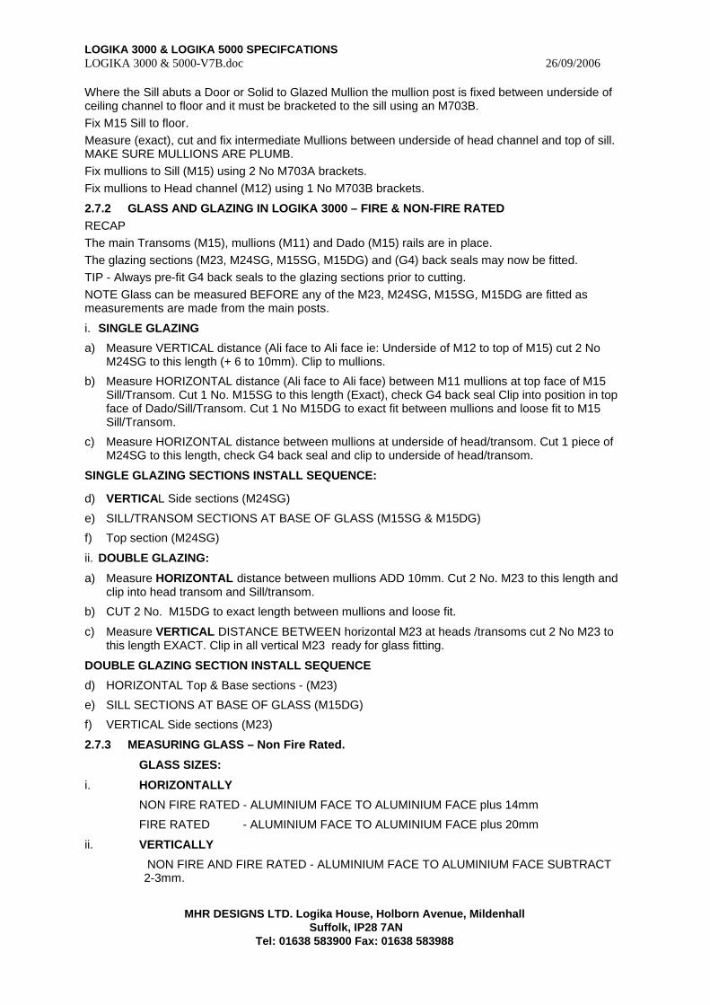
LOGIKA 3000 & LOGIKA 5000 SPECIFCATIONS LOGIKA 3000 & 5000-V7B.doc 26/09/2006
MHR DESIGNS LTD. Logika House, Holborn Avenue, Mildenhall
Suffolk, IP28 7AN Tel: 01638 583900 Fax: 01638 583988
Where the Sill abuts a Door or Solid to Glazed Mullion the mullion post is fixed between underside of ceiling channel to floor and it must be bracketed to the sill using an M703B. Fix M15 Sill to floor. Measure (exact), cut and fix intermediate Mullions between underside of head channel and top of sill. MAKE SURE MULLIONS ARE PLUMB. Fix mullions to Sill (M15) using 2 No M703A brackets. Fix mullions to Head channel (M12) using 1 No M703B brackets.
2.7.2 GLASS AND GLAZING IN LOGIKA 3000 – FIRE & NON-FIRE RATED RECAP The main Transoms (M15), mullions (M11) and Dado (M15) rails are in place. The glazing sections (M23, M24SG, M15SG, M15DG) and (G4) back seals may now be fitted. TIP - Always pre-fit G4 back seals to the glazing sections prior to cutting. NOTE Glass can be measured BEFORE any of the M23, M24SG, M15SG, M15DG are fitted as measurements are made from the main posts.
i. SINGLE GLAZING
a) Measure VERTICAL distance (Ali face to Ali face ie: Underside of M12 to top of M15) cut 2 No M24SG to this length (+ 6 to 10mm). Clip to mullions.
b) Measure HORIZONTAL distance (Ali face to Ali face) between M11 mullions at top face of M15 Sill/Transom. Cut 1 No. M15SG to this length (Exact), check G4 back seal Clip into position in top face of Dado/Sill/Transom. Cut 1 No M15DG to exact fit between mullions and loose fit to M15 Sill/Transom.
c) Measure HORIZONTAL distance between mullions at underside of head/transom. Cut 1 piece of M24SG to this length, check G4 back seal and clip to underside of head/transom.
SINGLE GLAZING SECTIONS INSTALL SEQUENCE:
d) VERTICAL Side sections (M24SG)
e) SILL/TRANSOM SECTIONS AT BASE OF GLASS (M15SG & M15DG)
f) Top section (M24SG)
ii. DOUBLE GLAZING:
a) Measure HORIZONTAL distance between mullions ADD 10mm. Cut 2 No. M23 to this length and clip into head transom and Sill/transom.
b) CUT 2 No. M15DG to exact length between mullions and loose fit.
c) Measure VERTICAL DISTANCE BETWEEN horizontal M23 at heads /transoms cut 2 No M23 to this length EXACT. Clip in all vertical M23 ready for glass fitting.
DOUBLE GLAZING SECTION INSTALL SEQUENCE
d) HORIZONTAL Top & Base sections - (M23)
e) SILL SECTIONS AT BASE OF GLASS (M15DG)
f) VERTICAL Side sections (M23)
2.7.3 MEASURING GLASS – Non Fire Rated.
GLASS SIZES:
i. HORIZONTALLY
NON FIRE RATED - ALUMINIUM FACE TO ALUMINIUM FACE plus 14mm
FIRE RATED - ALUMINIUM FACE TO ALUMINIUM FACE plus 20mm
ii. VERTICALLY
NON FIRE AND FIRE RATED - ALUMINIUM FACE TO ALUMINIUM FACE SUBTRACT 2-3mm.
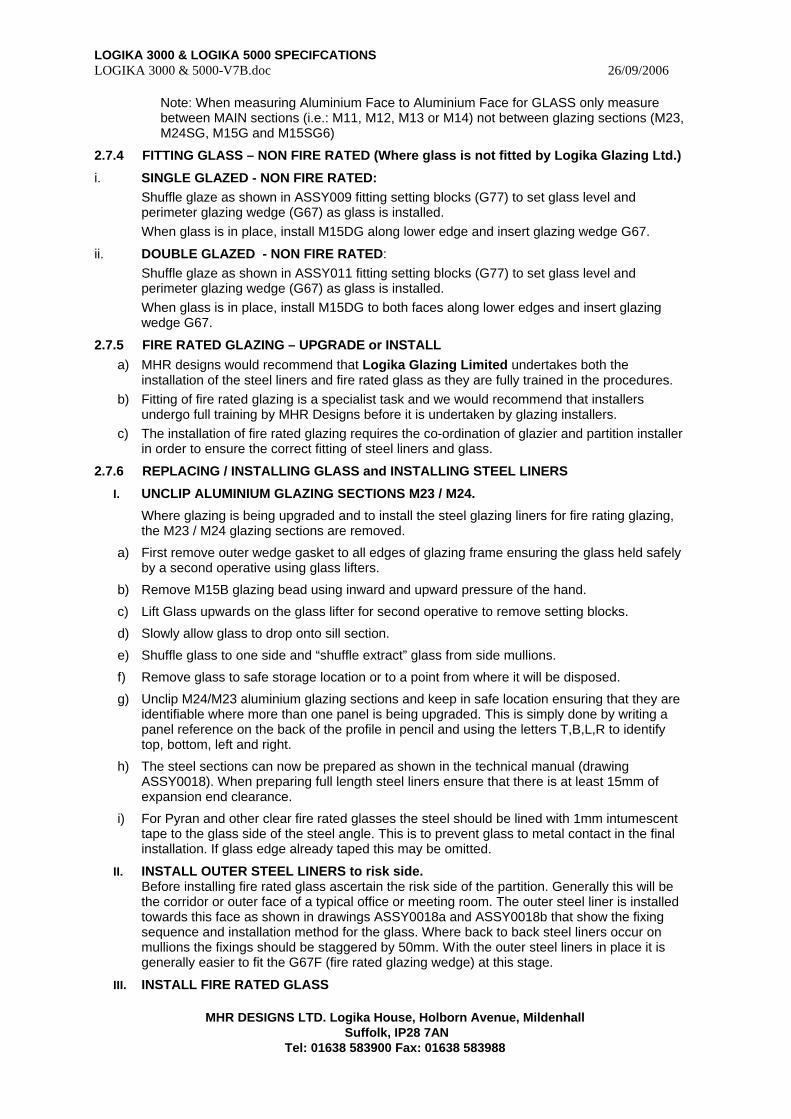
LOGIKA 3000 & LOGIKA 5000 SPECIFCATIONS LOGIKA 3000 & 5000-V7B.doc 26/09/2006
MHR DESIGNS LTD. Logika House, Holborn Avenue, Mildenhall
Suffolk, IP28 7AN Tel: 01638 583900 Fax: 01638 583988
Note: When measuring Aluminium Face to Aluminium Face for GLASS only measure between MAIN sections (i.e.: M11, M12, M13 or M14) not between glazing sections (M23, M24SG, M15G and M15SG6)
2.7.4 FITTING GLASS – NON FIRE RATED (Where glass is not fitted by Logika Glazing Ltd.)
i. SINGLE GLAZED - NON FIRE RATED: Shuffle glaze as shown in ASSY009 fitting setting blocks (G77) to set glass level and perimeter glazing wedge (G67) as glass is installed. When glass is in place, install M15DG along lower edge and insert glazing wedge G67.
ii. DOUBLE GLAZED - NON FIRE RATED: Shuffle glaze as shown in ASSY011 fitting setting blocks (G77) to set glass level and
perimeter glazing wedge (G67) as glass is installed. When glass is in place, install M15DG to both faces along lower edges and insert glazing
wedge G67.
2.7.5 FIRE RATED GLAZING – UPGRADE or INSTALL a) MHR designs would recommend that Logika Glazing Limited undertakes both the
installation of the steel liners and fire rated glass as they are fully trained in the procedures. b) Fitting of fire rated glazing is a specialist task and we would recommend that installers
undergo full training by MHR Designs before it is undertaken by glazing installers. c) The installation of fire rated glazing requires the co-ordination of glazier and partition installer
in order to ensure the correct fitting of steel liners and glass.
2.7.6 REPLACING / INSTALLING GLASS and INSTALLING STEEL LINERS
I. UNCLIP ALUMINIUM GLAZING SECTIONS M23 / M24.
Where glazing is being upgraded and to install the steel glazing liners for fire rating glazing, the M23 / M24 glazing sections are removed.
a) First remove outer wedge gasket to all edges of glazing frame ensuring the glass held safely by a second operative using glass lifters.
b) Remove M15B glazing bead using inward and upward pressure of the hand.
c) Lift Glass upwards on the glass lifter for second operative to remove setting blocks.
d) Slowly allow glass to drop onto sill section.
e) Shuffle glass to one side and “shuffle extract” glass from side mullions.
f) Remove glass to safe storage location or to a point from where it will be disposed.
g) Unclip M24/M23 aluminium glazing sections and keep in safe location ensuring that they are identifiable where more than one panel is being upgraded. This is simply done by writing a panel reference on the back of the profile in pencil and using the letters T,B,L,R to identify top, bottom, left and right.
h) The steel sections can now be prepared as shown in the technical manual (drawing ASSY0018). When preparing full length steel liners ensure that there is at least 15mm of expansion end clearance.
i) For Pyran and other clear fire rated glasses the steel should be lined with 1mm intumescent tape to the glass side of the steel angle. This is to prevent glass to metal contact in the final installation. If glass edge already taped this may be omitted.
II. INSTALL OUTER STEEL LINERS to risk side. Before installing fire rated glass ascertain the risk side of the partition. Generally this will be the corridor or outer face of a typical office or meeting room. The outer steel liner is installed towards this face as shown in drawings ASSY0018a and ASSY0018b that show the fixing sequence and installation method for the glass. Where back to back steel liners occur on mullions the fixings should be staggered by 50mm. With the outer steel liners in place it is generally easier to fit the G67F (fire rated glazing wedge) at this stage.
III. INSTALL FIRE RATED GLASS
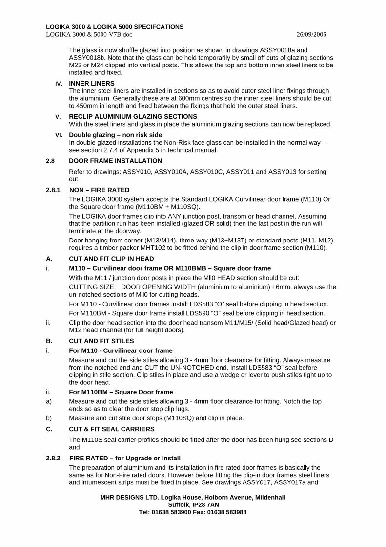
LOGIKA 3000 & LOGIKA 5000 SPECIFCATIONS LOGIKA 3000 & 5000-V7B.doc 26/09/2006
MHR DESIGNS LTD. Logika House, Holborn Avenue, Mildenhall
Suffolk, IP28 7AN Tel: 01638 583900 Fax: 01638 583988
The glass is now shuffle glazed into position as shown in drawings ASSY0018a and ASSY0018b. Note that the glass can be held temporarily by small off cuts of glazing sections M23 or M24 clipped into vertical posts. This allows the top and bottom inner steel liners to be installed and fixed.
IV. INNER LINERS The inner steel liners are installed in sections so as to avoid outer steel liner fixings through the aluminium. Generally these are at 600mm centres so the inner steel liners should be cut to 450mm in length and fixed between the fixings that hold the outer steel liners.
V. RECLIP ALUMINIUM GLAZING SECTIONS With the steel liners and glass in place the aluminium glazing sections can now be replaced.
VI. Double glazing – non risk side. In double glazed installations the Non-Risk face glass can be installed in the normal way – see section 2.7.4 of Appendix 5 in technical manual.
2.8 DOOR FRAME INSTALLATION
Refer to drawings: ASSY010, ASSY010A, ASSY010C, ASSY011 and ASSY013 for setting out.
2.8.1 NON – FIRE RATED The LOGIKA 3000 system accepts the Standard LOGIKA Curvilinear door frame (M110) Or the Square door frame (M110BM + M110SQ). The LOGIKA door frames clip into ANY junction post, transom or head channel. Assuming that the partition run has been installed (glazed OR solid) then the last post in the run will terminate at the doorway. Door hanging from corner (M13/M14), three-way (M13+M13T) or standard posts (M11, M12) requires a timber packer MHT102 to be fitted behind the clip in door frame section (M110).
A. CUT AND FIT CLIP IN HEAD i. M110 – Curvilinear door frame OR M110BMB – Square door frame
With the M11 / junction door posts in place the Mll0 HEAD section should be cut: CUTTING SIZE: DOOR OPENING WIDTH (aluminium to aluminium) +6mm. always use the un-notched sections of Mll0 for cutting heads. For M110 - Curvilinear door frames install LDS583 “O” seal before clipping in head section. For M110BM - Square door frame install LDS590 “O” seal before clipping in head section.
ii. Clip the door head section into the door head transom M11/M15/ (Solid head/Glazed head) or M12 head channel (for full height doors).
B. CUT AND FIT STILES i. For M110 - Curvilinear door frame
Measure and cut the side stiles allowing 3 - 4mm floor clearance for fitting. Always measure from the notched end and CUT the UN-NOTCHED end. Install LDS583 “O” seal before clipping in stile section. Clip stiles in place and use a wedge or lever to push stiles tight up to the door head.
ii. For M110BM – Square Door frame a) Measure and cut the side stiles allowing 3 - 4mm floor clearance for fitting. Notch the top
ends so as to clear the door stop clip lugs. b) Measure and cut stile door stops (M110SQ) and clip in place.
C. CUT & FIT SEAL CARRIERS
The M110S seal carrier profiles should be fitted after the door has been hung see sections D and
2.8.2 FIRE RATED – for Upgrade or Install The preparation of aluminium and its installation in fire rated door frames is basically the same as for Non-Fire rated doors. However before fitting the clip-in door frames steel liners and intumescent strips must be fitted in place. See drawings ASSY017, ASSY017a and
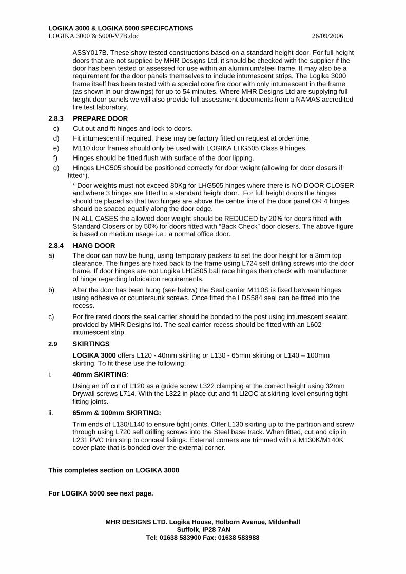
LOGIKA 3000 & LOGIKA 5000 SPECIFCATIONS LOGIKA 3000 & 5000-V7B.doc 26/09/2006
MHR DESIGNS LTD. Logika House, Holborn Avenue, Mildenhall
Suffolk, IP28 7AN Tel: 01638 583900 Fax: 01638 583988
ASSY017B. These show tested constructions based on a standard height door. For full height doors that are not supplied by MHR Designs Ltd. it should be checked with the supplier if the door has been tested or assessed for use within an aluminium/steel frame. It may also be a requirement for the door panels themselves to include intumescent strips. The Logika 3000 frame itself has been tested with a special core fire door with only intumescent in the frame (as shown in our drawings) for up to 54 minutes. Where MHR Designs Ltd are supplying full height door panels we will also provide full assessment documents from a NAMAS accredited fire test laboratory.
2.8.3 PREPARE DOOR c) Cut out and fit hinges and lock to doors. d) Fit intumescent if required, these may be factory fitted on request at order time. e) M110 door frames should only be used with LOGIKA LHG505 Class 9 hinges. f) Hinges should be fitted flush with surface of the door lipping. g) Hinges LHG505 should be positioned correctly for door weight (allowing for door closers if
fitted*). * Door weights must not exceed 80Kg for LHG505 hinges where there is NO DOOR CLOSER and where 3 hinges are fitted to a standard height door. For full height doors the hinges should be placed so that two hinges are above the centre line of the door panel OR 4 hinges should be spaced equally along the door edge. IN ALL CASES the allowed door weight should be REDUCED by 20% for doors fitted with Standard Closers or by 50% for doors fitted with “Back Check” door closers. The above figure is based on medium usage i.e.: a normal office door.
2.8.4 HANG DOOR a) The door can now be hung, using temporary packers to set the door height for a 3mm top
clearance. The hinges are fixed back to the frame using L724 self drilling screws into the door frame. If door hinges are not Logika LHG505 ball race hinges then check with manufacturer of hinge regarding lubrication requirements.
b) After the door has been hung (see below) the Seal carrier M110S is fixed between hinges using adhesive or countersunk screws. Once fitted the LDS584 seal can be fitted into the recess.
c) For fire rated doors the seal carrier should be bonded to the post using intumescent sealant provided by MHR Designs ltd. The seal carrier recess should be fitted with an L602 intumescent strip.
2.9 SKIRTINGS
LOGIKA 3000 offers L120 - 40mm skirting or L130 - 65mm skirting or L140 – 100mm skirting. To fit these use the following:
i. 40mm SKIRTING:
Using an off cut of L120 as a guide screw L322 clamping at the correct height using 32mm Drywall screws L714. With the L322 in place cut and fit Ll2OC at skirting level ensuring tight fitting joints.
ii. 65mm & 100mm SKIRTING:
Trim ends of L130/L140 to ensure tight joints. Offer L130 skirting up to the partition and screw through using L720 self drilling screws into the Steel base track. When fitted, cut and clip in L231 PVC trim strip to conceal fixings. External corners are trimmed with a M130K/M140K cover plate that is bonded over the external corner.
This completes section on LOGIKA 3000
For LOGIKA 5000 see next page.
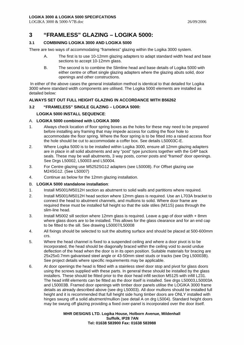
LOGIKA 3000 & LOGIKA 5000 SPECIFCATIONS LOGIKA 3000 & 5000-V7B.doc 26/09/2006
MHR DESIGNS LTD. Logika House, Holborn Avenue, Mildenhall
Suffolk, IP28 7AN Tel: 01638 583900 Fax: 01638 583988
3 “FRAMLESS” GLAZING – LOGIKA 5000: 3.1 COMBINING LOGIKA 3000 AND LOGIKA 5000
There are two ways of accommodating “frameless” glazing within the Logika 3000 system.
A. The first is to use 10-12mm glazing adapters to adapt standard width head and base sections to accept 10-12mm glass.
B. The second is to combine the Slimline head and base details of Logika 5000 with either centre or offset single glazing adapters where the glazing abuts solid, door openings and other constructions.
In either of the above cases the general installation method is identical to that detailed for Logika 3000 where standard width components are utilised. The Logika 5000 elements are installed as detailed below:
ALWAYS SET OUT FULL HEIGHT GLAZING IN ACCORDANCE WITH B56262
3.2 “FRAMELESS” SINGLE GLAZING – LOGIKA 5000:
LOGIKA 5000 INSTALL SEQUENCE:
A. LOGIKA 5000 combined with LOGIKA 3000 1. Always check location of floor spring boxes as the holes for these may need to be prepared
before installing any framing that may impede access for cutting the floor hole to accommodate the floor spring. Where the floor spring is to be fitted into a raised access floor the hole should be cut to accommodate a coffer box. See details L50003C-E.
2. Where Logika 5000 is to be installed within Logika 3000, ensure all 12mm glazing adapters are in place in all solid abutments and any “post” type junctions together with the G4P back seals. These may be wall abutments, 3 way posts, corner posts and “framed” door openings. See Drgs L50002, L50003 and L50004.
3. For Centre glazing use M5252SG12 adapters (see L50008). For Offset glazing use M24SG12. (See L50007)
4. Continue as below for the 12mm glazing installation.
B. LOGIKA 5000 standalone installation: 1. Install M5001/M5012H section as abutment to solid walls and partitions where required. 2. Install M5001/M5012H head section where 12mm glass is required. Use an L703A bracket to
connect the head to abutment channels, and mullions to solid. Where door frame are required these must be installed full height so that the side stiles (M11S) pass through the slim-line head.
3. Install M5002 sill section where 12mm glass is required. Leave a gap of door width + 8mm where glass doors are to be installed. This allows for the glass clearance and for an end cap to be fitted to the sill. See drawing L50007/L50008
4. All fixings should be selected to suit the abutting surface and should be placed at 500-600mm crs.
5. Where the head channel is fixed to a suspended ceiling and where a door pivot is to be incorporated, the head should be diagonally braced within the ceiling void to avoid undue deflection of the head when the door is in its open position. Suitable materials for bracing are 25x25x0.7mm galvanised steel angle or 43-50mm steel studs or tracks (see Drg L50003B). See project details where specific requirements may be applicable.
6. At door openings the head is fitted with a stainless steel door stop and pivot for glass doors using the screws supplied with these parts. In general these should be installed by the glass installers. These should be fitted prior to the door head infill section M5125 with infill L231. The head infill elements can be fitted as the door itself is installed. See drgs L50003,L50003A and L50003B. Framed door openings with timber door panels utilise the LOGIKA 3000 frame details as already described above (see drg L50003). All door mullions should be installed full height and it is recommended that full height side hung timber doors are ONLY installed with hinges swung off a solid abutment/mullion (see detail A on drg L5004). Standard height doors may be swung off glazing providing a fixed over-panel is incorporated over the door itself.

LOGIKA 3000 & LOGIKA 5000 SPECIFCATIONS LOGIKA 3000 & 5000-V7B.doc 26/09/2006
MHR DESIGNS LTD. Logika House, Holborn Avenue, Mildenhall
Suffolk, IP28 7AN Tel: 01638 583900 Fax: 01638 583988
3.3 GLASS AND GLAZING IN LOGIKA 5000
THE LOGIKA 5000 SYSTEM IS ONLY AVAILABLE WITH GLASS SUPPLIED & INSTALLED LOGIKA GLAZING LTD.
The following section is for information only.
RECAP
The main heads and abutments (M5001/M5012H), sills (M5002) and beads (M5003) rails are in place.
The glazing adapter sections (M24SG12, M525SG12 and G4 back seals are in place.
TIP - Always pre-fit G4 back seals to the glazing sections prior to cutting.
NOTE Glass can be measured BEFORE any of the adapters are fitted as measurements are made from the main posts, heads and sills.
1. The glass will be measured by LOGIKA GLAZING LTD or by a glazing specialist approved by MHR Designs Ltd.
2. There are two options for the glass installation:
a. Silicon bonded glazing.
b. Dry jointed using clear “Spectar” extrusions.
3. All glass will be installed in accordance with the relevant standards and in compliance with current Health and Safety requirements.
4. Manifestation will be applied to recommendations of the current building regulations requirements.
D. SINGLE GLAZING
MEASURING GLASS – THIS IS UNDERTAKEN BY LOGIKA GLAZING LTD
GLASS SIZES:
HORIZONTALLY
ALUMINIUM FACE TO ALUMINIUM FACE ADD 16mm for each glass run.
Allow 4mm per vertical joint and refer to drawing L5007 for allowances at corners and 3 way junctions.
VERTICALLY
ALUMINIUM FACE TO ALUMINIUM FACE ADD 20mm.
FITTING GLASS
Shuffle glaze and level glass using appropriate setting blocks. Fit perimeter glazing wedges to retain glass in position and silicon bond joints or fit dry joint trims at glazing joints as required. 90° dry joint corners should be bonded at the mid point using clear UV cure adhesive.
E. DOUBLE GLAZING – GHOST POST
Framework is installed in the same sequence as Logika 3000. The Glass and Ghost post profiles are supplied and installed by LOGIKA GLAZING LTD. following installation of framework by an approved Logika installer.
3.4 CLEAN DOWN:
With the installation complete remove all pencil marks and scuffs from the framework using Amberclens. Clean glass using supplied glass cleaner. Clean all handling marks from partition using Amberclens on Aluminium, PVC, and Vinyl etc.
3.5 DISMANTLE and RELOCATION

LOGIKA 3000 & LOGIKA 5000 SPECIFCATIONS LOGIKA 3000 & 5000-V7B.doc 26/09/2006
MHR DESIGNS LTD. Logika House, Holborn Avenue, Mildenhall
Suffolk, IP28 7AN Tel: 01638 583900 Fax: 01638 583988
LOGIKA 3000 and LOGIKA 5000 are both site assembled systems and dismantlement can be done at any time following installation by a qualified and approved installer of our products. Relocation of the system will depend on many factors, but key to this is the difference in floor levels between the existing location and the proposed location. The vertical tolerance of a system is almost entirely governed by the door opening where FULL height doors are employed, as whilst the head detail will have up to 12mm vertical tolerance over glazing there is always a limit at the door opening. To assist it is always worth considering a shadow head detail that runs over the entire partition at solid, glazing and door openings. It is also wise to ensure that floor ceiling heights are kept uniform within a project.
All Logika 3000 and Logika 5000 components are reusable as all fixing locations are hidden and all visible adapter sections are of a “clip-in” design. This provides maximum potential for the re-use of the main components during any relocation.
LOGIKA 3000 & LOGIKA 5000 SPECIFCATIONS LOGIKA 3000 & 5000-V7B.doc 26/09/2006
MHR DESIGNS LTD. Logika House, Holborn Avenue, Mildenhall
Suffolk, IP28 7AN Tel: 01638 583900 Fax: 01638 583988
APPENDIX 6
C.O.S.H.H
SAFETY INFORMATION
And General Method Statements
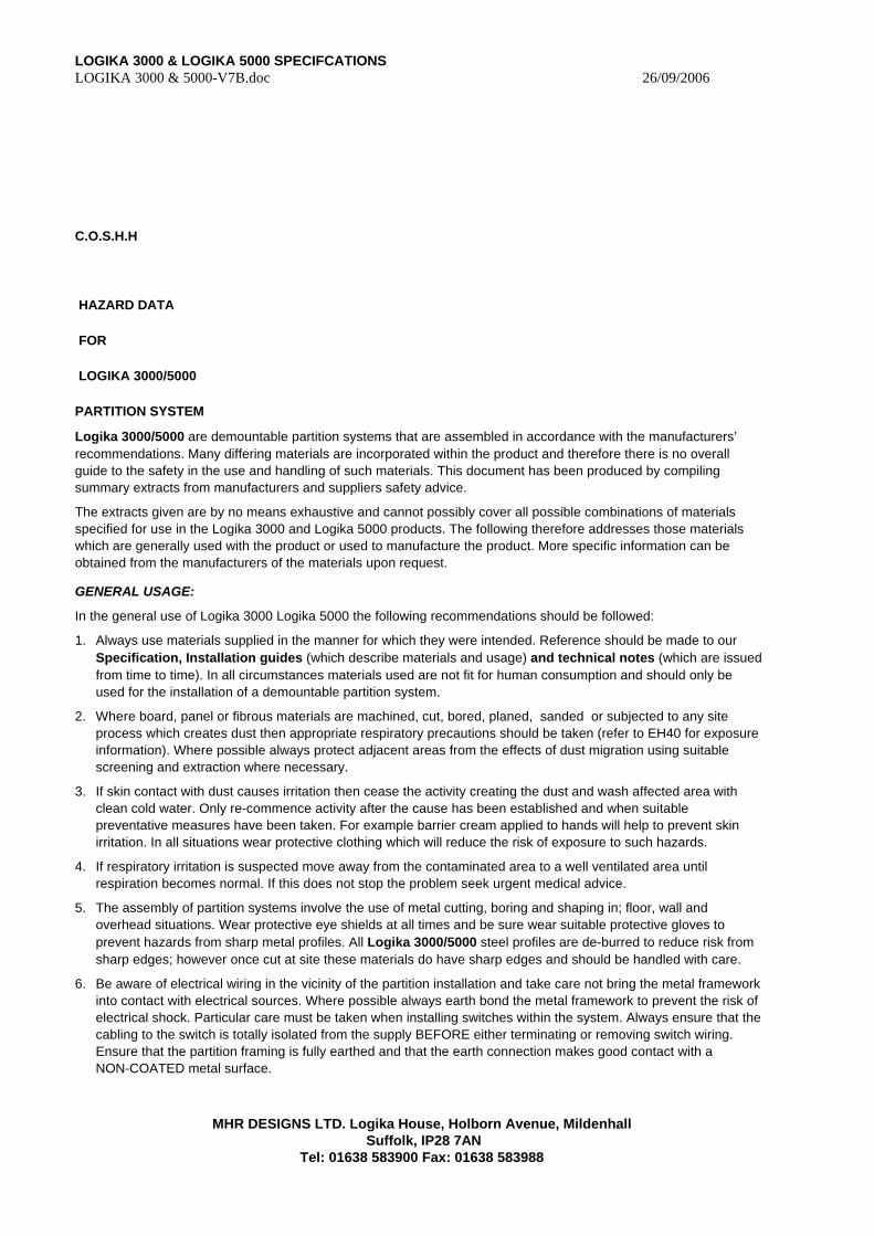
LOGIKA 3000 & LOGIKA 5000 SPECIFCATIONS LOGIKA 3000 & 5000-V7B.doc 26/09/2006
MHR DESIGNS LTD. Logika House, Holborn Avenue, Mildenhall
Suffolk, IP28 7AN Tel: 01638 583900 Fax: 01638 583988
C.O.S.H.H
HAZARD DATA
FOR
LOGIKA 3000/5000
PARTITION SYSTEM
Logika 3000/5000 are demountable partition systems that are assembled in accordance with the manufacturers’ recommendations. Many differing materials are incorporated within the product and therefore there is no overall guide to the safety in the use and handling of such materials. This document has been produced by compiling summary extracts from manufacturers and suppliers safety advice.
The extracts given are by no means exhaustive and cannot possibly cover all possible combinations of materials specified for use in the Logika 3000 and Logika 5000 products. The following therefore addresses those materials which are generally used with the product or used to manufacture the product. More specific information can be obtained from the manufacturers of the materials upon request.
GENERAL USAGE:
In the general use of Logika 3000 Logika 5000 the following recommendations should be followed:
1. Always use materials supplied in the manner for which they were intended. Reference should be made to our Specification, Installation guides (which describe materials and usage) and technical notes (which are issued from time to time). In all circumstances materials used are not fit for human consumption and should only be used for the installation of a demountable partition system.
2. Where board, panel or fibrous materials are machined, cut, bored, planed, sanded or subjected to any site process which creates dust then appropriate respiratory precautions should be taken (refer to EH40 for exposure information). Where possible always protect adjacent areas from the effects of dust migration using suitable screening and extraction where necessary.
3. If skin contact with dust causes irritation then cease the activity creating the dust and wash affected area with clean cold water. Only re-commence activity after the cause has been established and when suitable preventative measures have been taken. For example barrier cream applied to hands will help to prevent skin irritation. In all situations wear protective clothing which will reduce the risk of exposure to such hazards.
4. If respiratory irritation is suspected move away from the contaminated area to a well ventilated area until respiration becomes normal. If this does not stop the problem seek urgent medical advice.
5. The assembly of partition systems involve the use of metal cutting, boring and shaping in; floor, wall and overhead situations. Wear protective eye shields at all times and be sure wear suitable protective gloves to prevent hazards from sharp metal profiles. All Logika 3000/5000 steel profiles are de-burred to reduce risk from sharp edges; however once cut at site these materials do have sharp edges and should be handled with care.
6. Be aware of electrical wiring in the vicinity of the partition installation and take care not bring the metal framework into contact with electrical sources. Where possible always earth bond the metal framework to prevent the risk of electrical shock. Particular care must be taken when installing switches within the system. Always ensure that the cabling to the switch is totally isolated from the supply BEFORE either terminating or removing switch wiring. Ensure that the partition framing is fully earthed and that the earth connection makes good contact with a NON-COATED metal surface.
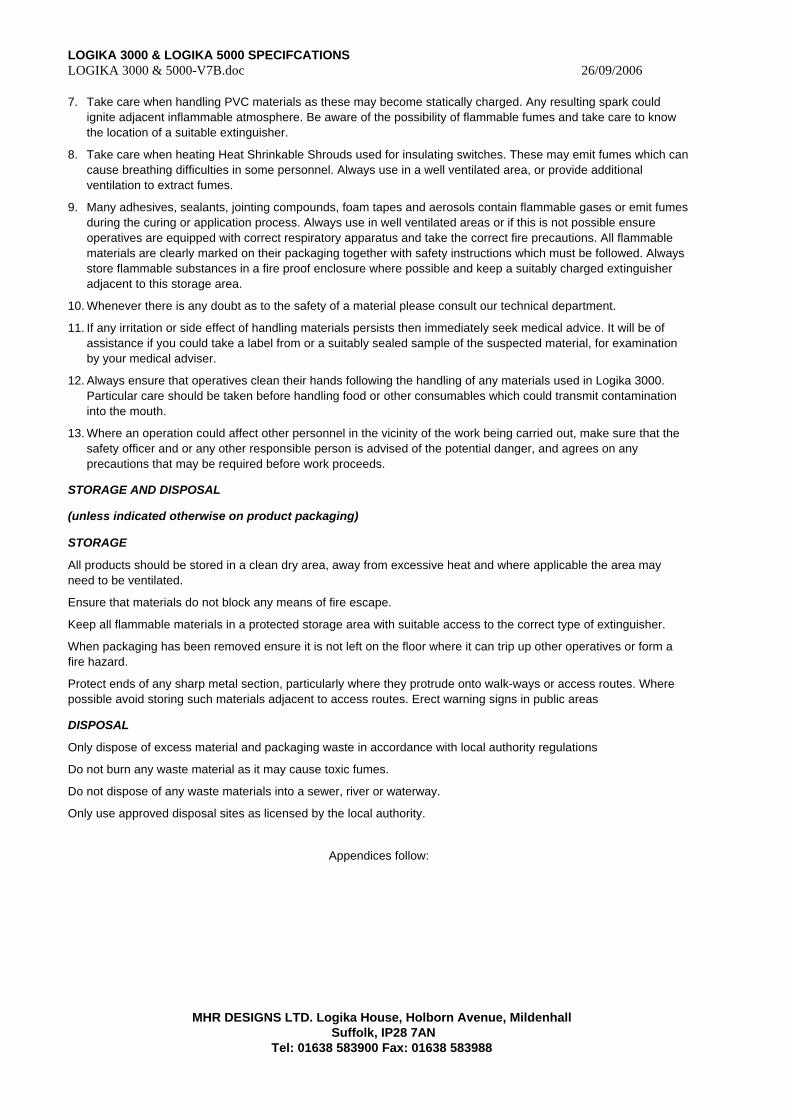
LOGIKA 3000 & LOGIKA 5000 SPECIFCATIONS LOGIKA 3000 & 5000-V7B.doc 26/09/2006
MHR DESIGNS LTD. Logika House, Holborn Avenue, Mildenhall
Suffolk, IP28 7AN Tel: 01638 583900 Fax: 01638 583988
7. Take care when handling PVC materials as these may become statically charged. Any resulting spark could ignite adjacent inflammable atmosphere. Be aware of the possibility of flammable fumes and take care to know the location of a suitable extinguisher.
8. Take care when heating Heat Shrinkable Shrouds used for insulating switches. These may emit fumes which can cause breathing difficulties in some personnel. Always use in a well ventilated area, or provide additional ventilation to extract fumes.
9. Many adhesives, sealants, jointing compounds, foam tapes and aerosols contain flammable gases or emit fumes during the curing or application process. Always use in well ventilated areas or if this is not possible ensure operatives are equipped with correct respiratory apparatus and take the correct fire precautions. All flammable materials are clearly marked on their packaging together with safety instructions which must be followed. Always store flammable substances in a fire proof enclosure where possible and keep a suitably charged extinguisher adjacent to this storage area.
10. Whenever there is any doubt as to the safety of a material please consult our technical department.
11. If any irritation or side effect of handling materials persists then immediately seek medical advice. It will be of assistance if you could take a label from or a suitably sealed sample of the suspected material, for examination by your medical adviser.
12. Always ensure that operatives clean their hands following the handling of any materials used in Logika 3000. Particular care should be taken before handling food or other consumables which could transmit contamination into the mouth.
13. Where an operation could affect other personnel in the vicinity of the work being carried out, make sure that the safety officer and or any other responsible person is advised of the potential danger, and agrees on any precautions that may be required before work proceeds.
STORAGE AND DISPOSAL
(unless indicated otherwise on product packaging)
STORAGE
All products should be stored in a clean dry area, away from excessive heat and where applicable the area may need to be ventilated.
Ensure that materials do not block any means of fire escape.
Keep all flammable materials in a protected storage area with suitable access to the correct type of extinguisher.
When packaging has been removed ensure it is not left on the floor where it can trip up other operatives or form a fire hazard.
Protect ends of any sharp metal section, particularly where they protrude onto walk-ways or access routes. Where possible avoid storing such materials adjacent to access routes. Erect warning signs in public areas
DISPOSAL
Only dispose of excess material and packaging waste in accordance with local authority regulations
Do not burn any waste material as it may cause toxic fumes.
Do not dispose of any waste materials into a sewer, river or waterway.
Only use approved disposal sites as licensed by the local authority.
Appendices follow:
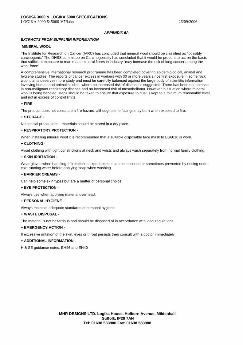
LOGIKA 3000 & LOGIKA 5000 SPECIFCATIONS LOGIKA 3000 & 5000-V7B.doc 26/09/2006
MHR DESIGNS LTD. Logika House, Holborn Avenue, Mildenhall
Suffolk, IP28 7AN Tel: 01638 583900 Fax: 01638 583988
APPENDIX 6A
EXTRACTS FROM SUPPLIER INFORMATION
MINERAL WOOL
The Institute for Research on Cancer (IARC) has concluded that mineral wool should be classified as "possibly carcinogenic" The DHSS committee on Carcinogenicity has concluded that it would be prudent to act on the basis that sufficient exposure to man made mineral fibres in industry "may increase the risk of lung cancer among the work-force"
A comprehensive international research programme has been completed covering epidemiological, animal and hygiene studies. The reports of cancer excess in workers with 30 or more years since first exposure in some rock wool plants deserves more study and must be carefully balanced against the large body of scientific information involving human and animal studies, where no increased risk of disease is suggested. There has been no increase in non-malignant respiratory disease and no increased risk of mesothelioma. However in situation where mineral wool is being handled, steps should be taken to ensure that exposure to dust is kept to a minimum reasonable level and not in excess of control limits.
+ FIRE -
The product does not constitute a fire hazard, although some facings may burn when exposed to fire.
+ STORAGE -
No special precautions - materials should be stored in a dry place.
+ RESPIRATORY PROTECTION -
When installing mineral wool it is recommended that a suitable disposable face mask to BS6016 is worn.
+ CLOTHING -
Avoid clothing with tight constrictions at neck and wrists and always wash separately from normal family clothing.
+ SKIN IRRITATION -
Wear gloves when handling. If irritation is experienced it can be lessened or sometimes prevented by rinsing under cold running water before applying soap when washing.
+ BARRIER CREAMS -
Can help some skin types but are a matter of personal choice.
+ EYE PROTECTION -
Always use when applying material overhead.
+ PERSONAL HYGIENE -
Always maintain adequate standards of personal hygiene.
+ WASTE DISPOSAL -
The material is not hazardous and should be disposed of in accordance with local regulations.
+ EMERGENCY ACTION -
If excessive irritation of the skin, eyes or throat persists then consult with a doctor immediately
+ ADDITIONAL INFORMATION -
H & SE guidance notes: EH46 and EH40

LOGIKA 3000 & LOGIKA 5000 SPECIFCATIONS LOGIKA 3000 & 5000-V7B.doc 26/09/2006
MHR DESIGNS LTD. Logika House, Holborn Avenue, Mildenhall
Suffolk, IP28 7AN Tel: 01638 583900 Fax: 01638 583988
APPENDIX 6B
EXTRACTS FROM SUPPLIER INFORMATION
PLASTERBOARD
+ FIRE -
The product does not constitute a fire hazard, although facings may burn when exposed to fire.
+ STORAGE -
Always carry boards singly on one edge, do not drag one board over the other - materials should be stored in a dry place protected against damp on a level surface. Maximum stack height should be 1000mm.
+ RESPIRATORY PROTECTION -
When cutting or sanding plasterboard in confined spaces it is recommended that a suitable disposable face mask to BS6016 is worn. Use dust extraction if dust levels cannot be controlled by ventilation.
+ CLOTHING -
Avoid clothing with tight constrictions at neck and wrists and always wash separately from normal family clothing.
+ SKIN IRRITATION -
Wear gloves when handling. If irritation is experienced it can be lessened or sometimes prevented by rinsing under cold running water before applying soap when washing.
+ BARRIER CREAMS -
Can help some skin types but are a matter of personal choice.
+ EYE PROTECTION -
Always use when cutting or sanding plaster boards. If dust enters eye then wash with plenty of clean water.
+ PERSONAL HYGIENE -
Always maintain adequate standards of personal hygiene. If gypsum dust is swallowed wash out mouth and drink plenty of water. There are no biological hazards from the intake of Gypsum dust.
+ WASTE DISPOSAL -
The material is not hazardous and should be disposed of in accordance with local regulations at a tip designated for building products.
+ EMERGENCY ACTION -
If excessive irritation of the skin, eyes or throat persist then consult with a doctor immediately.
+ ADDITIONAL INFORMATION -
H & SE guidance notes: EH40
+ EXPOSURE LIMITS -
Total inhalable dust = 10mg/m3 hour time weighted average Respirable dust = 5mg/m3 hour time weighted average
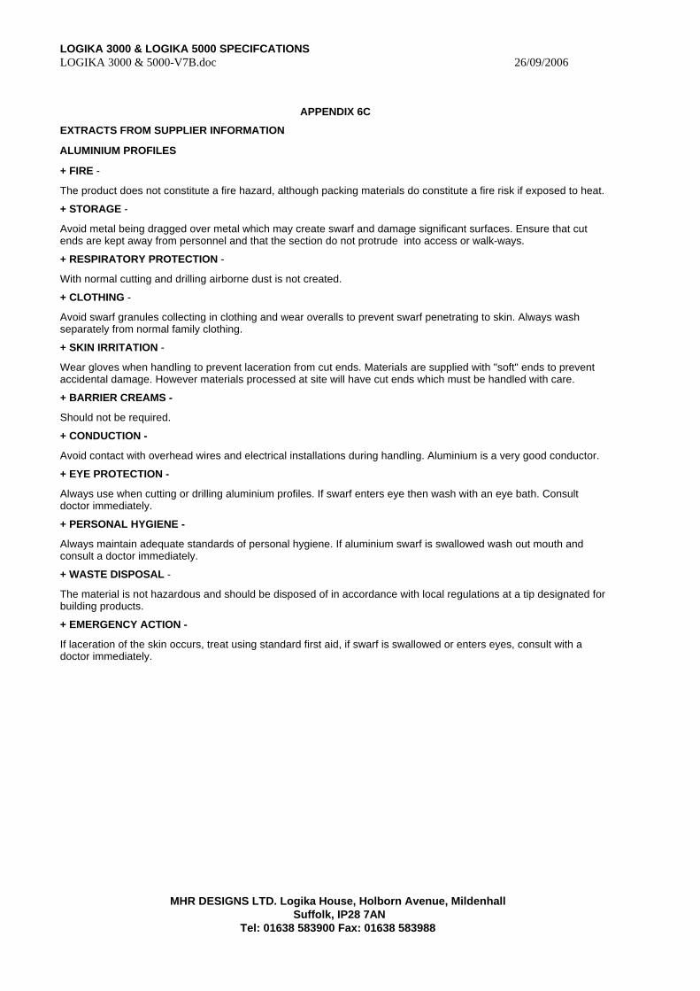
LOGIKA 3000 & LOGIKA 5000 SPECIFCATIONS LOGIKA 3000 & 5000-V7B.doc 26/09/2006
MHR DESIGNS LTD. Logika House, Holborn Avenue, Mildenhall
Suffolk, IP28 7AN Tel: 01638 583900 Fax: 01638 583988
APPENDIX 6C
EXTRACTS FROM SUPPLIER INFORMATION
ALUMINIUM PROFILES
+ FIRE -
The product does not constitute a fire hazard, although packing materials do constitute a fire risk if exposed to heat.
+ STORAGE -
Avoid metal being dragged over metal which may create swarf and damage significant surfaces. Ensure that cut ends are kept away from personnel and that the section do not protrude into access or walk-ways.
+ RESPIRATORY PROTECTION -
With normal cutting and drilling airborne dust is not created.
+ CLOTHING -
Avoid swarf granules collecting in clothing and wear overalls to prevent swarf penetrating to skin. Always wash separately from normal family clothing.
+ SKIN IRRITATION -
Wear gloves when handling to prevent laceration from cut ends. Materials are supplied with "soft" ends to prevent accidental damage. However materials processed at site will have cut ends which must be handled with care.
+ BARRIER CREAMS -
Should not be required.
+ CONDUCTION -
Avoid contact with overhead wires and electrical installations during handling. Aluminium is a very good conductor.
+ EYE PROTECTION -
Always use when cutting or drilling aluminium profiles. If swarf enters eye then wash with an eye bath. Consult doctor immediately.
+ PERSONAL HYGIENE -
Always maintain adequate standards of personal hygiene. If aluminium swarf is swallowed wash out mouth and consult a doctor immediately.
+ WASTE DISPOSAL -
The material is not hazardous and should be disposed of in accordance with local regulations at a tip designated for building products.
+ EMERGENCY ACTION -
If laceration of the skin occurs, treat using standard first aid, if swarf is swallowed or enters eyes, consult with a doctor immediately.

LOGIKA 3000 & LOGIKA 5000 SPECIFCATIONS LOGIKA 3000 & 5000-V7B.doc 26/09/2006
MHR DESIGNS LTD. Logika House, Holborn Avenue, Mildenhall
Suffolk, IP28 7AN Tel: 01638 583900 Fax: 01638 583988
APPENDIX 6D
EXTRACTS FROM SUPPLIER INFORMATION
STEEL SECTIONS
+ FIRE -
The product does not constitute a fire hazard.
+ STORAGE -
Avoid metal being dragged over metal which may create swarf Ensure that cut ends are protected and do not protrude into access or walk-ways.
+ RESPIRATORY PROTECTION -
With normal cutting and drilling airborne dust is not created.
+ CLOTHING -
Avoid swarf granules collecting in clothing and wear overalls to prevent swarf penetrating to skin. Always wash separately from normal family clothing.
+ SKIN IRRITATION -
Wear gloves when handling to prevent laceration from cut ends. Materials are supplied with "soft" ends to prevent accidental damage. However materials processed at site will have cut ends which must be handled with care. The sections may be covered with residual oils from the manufacturing process. Avoid contact with skin.
+ BARRIER CREAMS -
Can help some skin types but are a matter of personal choice.
+ CONDUCTION -
Avoid contact with overhead wires and electrical installations during handling. Steel is a very good conductor.
+ EYE PROTECTION -
Always use when cutting or drilling aluminium profiles. If swarf enters eye then wash with an eye bath. Consult doctor immediately. Take care when cutting away strapping which binds steel profiles as it may cause injury as the tension is released. Sparks from mechanical cutting may be hazardous.
+ PERSONAL HYGIENE -
Always maintain adequate standards of personal hygiene. If steel swarf is swallowed wash out mouth and consult a doctor immediately.
+ WASTE DISPOSAL -
The material is not hazardous and should be disposed of in accordance with local regulations at a tip designated for building products.
+ EMERGENCY ACTION -
If laceration of the skin occurs treat using standard first aid, if swarf is swallowed or enters eyes, consult with a doctor immediately.
LOGIKA 3000 & LOGIKA 5000 SPECIFCATIONS LOGIKA 3000 & 5000-V7B.doc 26/09/2006
MHR DESIGNS LTD. Logika House, Holborn Avenue, Mildenhall
Suffolk, IP28 7AN Tel: 01638 583900 Fax: 01638 583988
APPENDIX 6E
EXTRACTS FROM SUPPLIER INFORMATION
PVC SECTIONS
+ Although not hazardous in normal use the hazards resulting as a consequence of cutting or fire in relation to PVC are significant. The full information is given on the attached data sheet provided by Hydro Polymers see APPENDIX 7
OTHER ASSOCIATED PRODUCTS
Logika 3000 can incorporate many other products subject to specification, for information on these items please consult the supplier/manufacturer providing these materials.:
DOOR PANELS, IRONMONGERY, GLASS, BLINDS, ELECTRICAL ITEMS, WALL COVERINGS, VENEERED PANELS, PERIMETER SEALS ASSOCIATED WITH EXISTING FLOOR/CEILING VOIDS, ADHESIVES, FIXINGS, etc.
IF IN DOUBT PLEASE CONTACT OUR TECHNICAL DEPARTMENT:
TEL: 01638 583900 FAX: 01638 583988
LOGIKA 3000 & LOGIKA 5000 SPECIFCATIONS LOGIKA 3000 & 5000-V7B.doc 26/09/2006
MHR DESIGNS LTD. Logika House, Holborn Avenue, Mildenhall
Suffolk, IP28 7AN Tel: 01638 583900 Fax: 01638 583988
APPENDIX 6F
GENERAL METHOD STATEMENT FOR THE INSTALLATION OF LOGIKA PARITITON SYSTEMS.
This statement should be read in conjunction with the attached Technical Manual and COSSH Safety Information.
MHR provides this statement on the basis that MHR Designs Ltd. is a “supply only” company and that the information detailed below is for incorporation within an overall “Method Statement” prepared by the individual sub-contractor who has been contracted to install our products (The installing Sub Contractor).
MHR Designs Ltd operates a policy of training for all our products and it assumed that the sub contract installation team has undergone training either at our own premises, or by way of on-site training supervised by MHR personnel. Subject to the complexity of an intended installation MHR Designs Ltd may require the sub contract installation team to attend detailed training at our premises to cover specific construction elements where site program OR other constraints prevent adequate training of the sub contactor installation team.
It is assumed that sub contractor responsible for the installation of our products has appointed a suitably qualified or experienced Site Supervisor who is conversant with the relevant installation issues of our products, and is familiar with all relevant standards and codes of practice for the carrying out of the installation. The Site Supervisor will be ultimately responsible for ensuring that all the requirements of this Method Statement are met and that the “As built” assembly is consistent with the clients’ layout and performance requirements.
Description of Works
1.1 The installation of Logika 3000 or Logika 5000 partition system by an approved installer and subsequent installation of glass by Logika Glazing Ltd (See separate Method Statement for Logika Glazing Ltd in Appendix 6G attached).
2. Sequence of Operations
2.1 At commencement The Installing Sub Contractors will appoint a Site Supervisor who will have ultimate responsibility for safety and coordination of material deliveries, off-loading and site access.
2.2 The Installing Sub Contractor should arrange for adequate access to the site by our delivery vehicle and for unloading equipment and suitably trained personnel for the unloading of our materials. It is recommended that veneered doors are delivered after the initial phase of installation has been completed to avoid damage and unnecessary handling.
2.3 The Installing Sub Contractor will provide labour for safely distributing the materials from the unloading point to a location of safe, secure and dry storage close to the point of installation.
2.4 The Installing Sub Contractor will set up a safe working area for preparation of the Logika 3000/5000 materials, and provide adequate lighting, ventilation and guarding for any equipment used for the preparation of the materials.
2.5 Where required The Installing Sub Contractor will provide protection to existing surfaces.
2.6 All operatives engaged in the manoeuvring of the materials shall be fully competent and aware of the risks associated with the manual handling aspects of the task.
2.7 It is in the interest of safety during handling and to limit damage to completed framing by following trades, that the partition is installed as late a possible in the site programme and when the number of other trades operating in the vicinity of the installation point or along the distribution route between the off loading area and the installation point is at a minimum. In particular partition installation should be programmed to avoid areas where :
i. Flooring or screeding is being laid.
ii. Ceilings are incomplete.
iii. The building envelope is not fully sealed against damp and moisture.
2.8 Installation of the Logika 3000 / Logika 5000 partition system shall be carried out in accordance with APPENDIX 5 of the Technical Manual in conjunction with any special details shown in APPENDIX 4 for Project Specific Details.
2.9 Refuse bags of the correct type shall be provisioned at locations within the work area to enable ease of access. The Site Supervisor shall ensure that waste and debris levels are continually monitored and cleared away at the earliest opportunities.
2.10 Where debris and other materials are transported to alternative floors for storage or removal via a lift or hoist care will be taken so as to avoid exceeding the safe working load of the lift or hoist.
LOGIKA 3000 & LOGIKA 5000 SPECIFCATIONS LOGIKA 3000 & 5000-V7B.doc 26/09/2006
MHR DESIGNS LTD. Logika House, Holborn Avenue, Mildenhall
Suffolk, IP28 7AN Tel: 01638 583900 Fax: 01638 583988
2.11 When debris is being cleared, care shall be taken to ensure that dust and noise is kept to a minimum thereby reducing the disturbance to any of the buildings current occupants. The Installing Sub Contractor will provide refuse bags of the correct type that shall be provisioned at locations within the work area to enable ease of access. The Site Supervisor shall ensure that waste and debris levels are continually monitored and cleared away at the earliest opportunities.
2.12 If any large items or lengths of waste material (over 2 metres long) are required to be removed then two persons shall undertake the task with the lead person co-ordinating the lift, whilst maintaining a high level of visual awareness for obstructions and pedestrian movements.
2.13 If due to space restrictions, the siting of a refuse skip is impossible, The Installing Sub Contractor will arrange to remove the bagged waste and dispose of it in safe manner by transferring the waste to licensed tips accepting builders waste. This method of removing rubbish will be supported, in extreme circumstances only, by the removal and transfer of non-hazardous waste and debris via the Main Contractors vehicles to a licensed tip accepting Builders waste with any transfer documentation being retained by the parties concerned.
2.14 When work is completed all protective coverings shall be removed and all areas left clean and tidy.
3. SUPERVISION CONTROLS AND MONITORING
3.1 All work will be directly controlled by the Site Supervisor, who will ensure that the safe means of working, as given by this method statement are complied with.
4. OPERATOR TRAINING AND PLANT
4.1 All operatives employed or sub-contracted to The Installing Sub Contractor will be experienced and trained in the work that they are undertaking. Further training will be provided by MHR Design on request from The Installing Sub Contractor.
4.2 Plant and machinery will be operated only by those competent and adequately trained in its use.
4.3 Power tools will be checked at regular intervals and a visual inspection carried out before use. Power tools will be 110 volts or less and shall be subject to portable appliance testing at 3 monthly intervals.
5. SAFETY OF THIRD PARTIES
5.1 The Installing Sub Contractor will ensure all employees and sub-contractors will be made aware of any risks their work can impose on others in the vicinity. Work will only be undertaken so as to minimise these risks or when adequate protection is in place.
5.2 The Site Supervisor will liaise with the employees and sub-contractors to ensure that protection against all potential risks concerned with this activity is adequate.
6. ENVIRONMENTAL CONTROLS
6.1 Every effort will be made to keep noise, dust and waste levels to a minimum, and to ensure that they do not cause a hazard or become a nuisance to others. Working areas will be tidied regularly and waste removed to a temporary storage area provided.
7. PERSONAL PROTECTIVE EQUIPMENT
7.1 All operatives engaged on this operation shall be provided with appropriate personal protective equipment where necessary, operatives involved with the task contained within this method statement shall wear suitable hand, eye and respiratory protection and safety footwear when necessary.
7.2 All operatives shall be made aware of first-aid and emergency procedures on their arrival to site.
8. NON-STANDARD ACTIVITIES
8.1 Should any non-standard activities arise out of these operations they shall be addressed immediately on site by the trade foreman who will notify head office management immediately who will advise on the preparation of any required additional risk assessments prior to the works commencing.
LOGIKA 3000 & LOGIKA 5000 SPECIFCATIONS LOGIKA 3000 & 5000-V7B.doc 26/09/2006
MHR DESIGNS LTD. Logika House, Holborn Avenue, Mildenhall
Suffolk, IP28 7AN Tel: 01638 583900 Fax: 01638 583988
APPENDIX 6G
GENERAL METHOD STATEMENT FOR A GLAZING INSTALLATION BY LOGIKA GLAZING LIMITED (LGL)
1. DESCRIPTION/SCOPE OF THE WORKS The works contained within this method statement consist of: 1.1 Handling glazed panels from the delivery point to the point of installation through areas of the premises
that may be occupied by other contractors or by clients personnel 1.2 The installation of glazed panels and glass doors into a pre-installed framing system. 1.3 (where applicable) The installation of blinds or The application of Manifestation film.
2. Pre-delivery and Installation requirements. 2.1 It is the installing sub contractors’ responsibility to arrange for the preparation holes to accommodate raised
floor coffer boxes for glass doors on floor springs. Where this is delegated to LGL the installing sub contractors must ensure that the location of the proposed coffer boxes is not impeded by any pre-existing cabling, paperwork or ductwork and that the floor construction is adequate to support the coffer box and weight of the installed glass door.
2.2 It is the installing sub contractors’ responsibility to ensure that (where applicable) all free issue ironmongery for glass doors is available to LGL for installation at least 24 hours ahead of the agreed commencement date for glass installation. NOTE: Any delay to installation due to the late arrival of “free issue” glass door ironmongery will be charged at LGL’s standard day work rates.
3. ACCESS for DELIVERY and DISTRIBUTION OF GLASS PANELS 3.1 The installing sub contractor should arrange for adequate access to the site by the delivery vehicle and for
unloading equipment and suitably trained personnel for the unloading of our materials to the DELIVERY POINT
3.2 THE DELIVERY POINT is a location where glass sheets can be safely stored during the time it takes for distribution of the glass panels to the INSTALLATION POINT. The installing sub contractor will supervise and arrange all aspects of the unloading procedure and ensure that adequate provision is made for the safe handling of the glass sheets from the delivery location to the point of installation by LGL.
3.3 It is the installing sub contractor responsibility to arrange for adequate lifting equipment to lift glass delivered on “A” frames onto the floor level of the INSTALLATION POINT. Where this is not possible then provision must be made for clear access to either a hoist or lift of adequate capacity and dimensions to accept the largest glass panel size being delivered.
3.4 Where there is a high risk of damage from following trades, It is recommended that Glass doors are delivered and installed after the initial phase of installation has been completed to avoid damage by following trades and unnecessary replacement of glass doors.
3.5 Access routes to the INSTALLATION POINTS concerned will be need to be clear, free of any obstructions and level so as to allow glass panels to be distributed using wheeled trolleys designed to safely transfer panels from the off-loading point to the point of installation.
3.6 Manual transfer of glass from the point of delivery to the installation location should be avoided if at all possible.
3.7 The installing sub contractor should arrange for all other trades and sub contractors to be aware of the movement of glass and arrange that the routes between the off-loading point and installation point to be vacated of all other trades that could create a risk of damage or breakage to the glass as it is being transported between the delivery point and the installation point.
3.8 The Installing Sub contractor will arrange for the positioning of suitable signage and hazard safety tape to indicate the access route where the risk of damage to the glass by other trades is considered to be high risk.
3.9 The Installing Sub Contractor will arrange for adequate lighting for both the Access route and the Installation points so as to enable the safe handling of glass and to allow proper cleaning of the glass following installation.
4. SEQUENCE OF OPERATIONS 4.1 At commencement our working on-site foreman will liaise with The Installing Sub Contractors Site Supervisor
who will have ultimate responsibility for safety. 4.2 Where necessary, prior to the work commencing The Site Supervisor will arrange for suitable floor protection
shall be laid with any paint work or fragile surfaces adequately protected with jointed coverings along any access routes that glass will be transported.
4.3 Where the ONLY access route is also a fire escape route LGL recommended that the installation should take place when the building is unoccupied or as other wise agreed with The Installing Sub Contractors Site Supervisor.

LOGIKA 3000 & LOGIKA 5000 SPECIFCATIONS LOGIKA 3000 & 5000-V7B.doc 26/09/2006
MHR DESIGNS LTD. Logika House, Holborn Avenue, Mildenhall
Suffolk, IP28 7AN Tel: 01638 583900 Fax: 01638 583988
4.4 Where the access route to one of at least two fire escape routes LGL will ensure that only one escape route is be used for the transport of glass panels from the delivery point to the installation location point.
4.5 All operatives engaged in the manoeuvring of the glazing shall be fully competent and aware of the risks associated with the manual handling aspects of the task.
4.6 Glass will be installed in accordance with the recommendations of the glazing frame manufacturer. It is the responsibility of The Installing Sub Contractors Site Supervisor to ensure Logika Glazing Ltd is provided with all necessary information relevant to the installed framing system.
4.7 Clear and level access must be provided to both faces of the glazing to enable safe installation of the glass. Where glass is being installed at high level (e.g. in an Atrium location) The Installing Sub Contractors Site Supervisor will arrange for suitable scaffolding and access equipment complying with the relevant safety standards to be provided for the exclusive use of Logika Glazing Ltd. operatives.
4.8 It is in the interest of safety during handling and to limit damage to completed glazing by following trades, that the glass should be installed as late a possible in the site programme and when the number of other trades operating in the vicinity of the installation point or along the Access route between the off loading area and the installation point is at a minimum.
4.9 In the interests of safety glass installation should not be programmed to occur at the same time as furniture is being fitted or manoeuvred in the installation area or along the Access Route .
4.10 Film applied Manifestation and the glass will be cleaned by LGL. Any follow-up cleaning should only be carried out after the film has FULLY cured. See Section 4 below
4.11 The Installing Sub Contractors Site Supervisor will be responsible for the inspection and signing off of completed areas and for arranging protection of completed works.
4.12 Where installation is phased over a number of visits or locations each completed phase will be inspected and signed off by the Installing Sub Contractors Site Supervisor and will arrange each completed phase to be protected from following trades.
4.13 When work is completed all protective coverings shall be removed and all areas left clean and tidy.
5. Film Applied Manifestation 5.1 Film applied manifestation MUST be installed in a dust free atmosphere to avoid contamination of the
adhesive bond. The installing subcontractors Site Supervisor will ensure that all dust creating activities are ceased during the period of film application and for at least 24 hours “DRYING TIME”
5.2 ‘CURING TIME’ will be approximately 30 days, whilst thicker grades of film could increase the drying period. Glazing should not be touched or washed during this period.
5.3 Where an installation of Double glazing incorporates film manifestation within a double glazing void, the a film must be allowed at least 24 hours “DRYING TIME” before the second layer of glass is installed.
6. Blind installation 6.1 Blinds MUST be installed in a dust free atmosphere to avoid contamination of the glazing void in double
glazing. The installing subcontractors Site Supervisor will ensure that all dust creating activities are ceased during the period of blind installation until the glazed modules is fully closed by the second panel of glass.
6.2 Cleaning of the Blinds in a single glazed configuration will the responsibility of The Installing Sub Contractor.
7. Waste Disposal 7.1 Refuse bags of the correct type shall be provisioned at locations within the work area to enable ease of
access. The Site Supervisor shall ensure that waste and debris levels are continually monitored and cleared away at the earliest opportunities.
7.2 The Site Supervisor will designate a safe disposal point for any glass breakages and will liaise with LGL for the safe disposal of any broken glass.
7.3 Where glass is broken by following trades or non-LGL personnel it is the responsibility of that trade or persons Supervisor to arrange for the safe collection and disposal of any broken glass fragments.
7.4 Where debris and other materials are transported to alternative floors for storage or removal via lift or hoist care will be taken so as to avoid exceeding the safe working load of the lift/hoist.
7.5 When debris is being cleared, care shall be taken to ensure that dust and noise is kept to a minimum thereby reducing the disturbance to any of the buildings current occupants.
7.6 If any large items or lengths of waste material (over 2 mtr long) are required to be removed then two persons shall undertake the task with the lead person coordinating the lift, whilst maintaining a high level of visual awareness for obstructions and pedestrian movements.
7.7 If due to space restrictions, the siting of a refuse skip is impossible, arrangements will be made to remove the bagged waste and dispose of it in safe manner by transferring the waste to licensed tips accepting builders waste.
8. SUPERVISION CONTROLS AND MONITORING
LOGIKA 3000 & LOGIKA 5000 SPECIFCATIONS LOGIKA 3000 & 5000-V7B.doc 26/09/2006
MHR DESIGNS LTD. Logika House, Holborn Avenue, Mildenhall
Suffolk, IP28 7AN Tel: 01638 583900 Fax: 01638 583988
8.1 The Installing Sub Contractors Site Supervisor will have ultimate responsibility for safety and supervision. 8.2 All work carried out by Logika Glazing Ltd will be directly controlled by the LGL on-site trade foreman, who
will ensure that the safe means of working, as given by this method statement are complied with. 8.3 Additional supervision will be on hand from the offices of Logika Glazing Ltd when required.
9. OPERATOR TRAINING AND PLANT 9.1 All operatives employed or sub-contracted to LGL will be experienced and trained in the work that they are
undertaking. Further training will be provided if found to be required. 9.2 Plant and machinery will be operated only by those competent and adequately trained in its use. 9.3 Power tools will be checked at regular intervals and a visual inspection carried out before use. Power tools
will be 110 volts or less and shall be subject to portable appliance testing at 6 monthly intervals.
10. SAFETY OF THIRD PARTIES 10.1 All LGL employees and sub-contractors will be made aware of any risks their work can impose on others in
the vicinity. Work will only be undertaken when these risks are minimised or adequate protection is in place. 10.2 The on-site trade foreman will liaise with the employees and sub-contractors to ensure that protection against
all potential risks concerned with this activity is adequate.
11. ENVIRONMENTAL CONTROLS 11.1 Every effort will be made to keep noise, dust and waste levels to a minimum, and to ensure that they do not
cause a hazard or become a nuisance to others. Working areas will be tidied regularly and waste removed to a temporary storage area provided.
12. PERSONAL PROTECTIVE EQUIPMENT 12.1 All LGL operatives shall be provided with appropriate personal protective equipment where necessary,
operatives involved with the task contained within this method statement shall wear suitable hand protection and safety footwear when necessary.
12.2 All operatives shall be made aware of first-aid and emergency procedures on their arrival to site.
13. NON-STANDARD ACTIVITIES 13.1 Should any non-standard activities arise out of these operations they shall be addressed immediately on site
by the trade foreman who will notify head office management immediately who will advise on the preparation of any required additional risk assessments prior to the works commencing.
LOGIKA 3000 & LOGIKA 5000 SPECIFCATIONS LOGIKA 3000 & 5000-V7B.doc 26/09/2006
MHR DESIGNS LTD. Logika House, Holborn Avenue, Mildenhall
Suffolk, IP28 7AN Tel: 01638 583900 Fax: 01638 583988
APPENDIX 7
PVC INFORMATION SHEETS
LOGIKA 3000 & LOGIKA 5000 SPECIFCATIONS LOGIKA 3000 & 5000-V7B.doc 26/09/2006
MHR DESIGNS LTD. Logika House, Holborn Avenue, Mildenhall
Suffolk, IP28 7AN Tel: 01638 583900 Fax: 01638 583988
UPvc Components
1. INTRODUCTION
This publication outlines the precautions which should be taken in the handling of compositions made from vinyl chloride polymers (PVC) andco-polymers, and has been prepared in conjunction with the British Plastics Federation. The compositions are made from PVC polymers and/or co-polymers by blending with a variety of additives such as stabilisers, plasticisers, fillers, pigments etc. They should not be confused with PVC polymers which may require different precautions in handling. Further information on PVC polymers can be found in Hydro Polymers Limited publication "A Guide to the handling of PVC Resins". PVC compositions are described in several ways, the most common being:
Physical Form
Description
Powder PVC dry blend, powder blend, colour powder concentrate Pellet PVC granulate, pellet, compound, masterbatch, colour concentrate. Liquid/Paste PVC plastisol . organosol Dough/Jelly Hot melt compound (H.M C.) ,Extrusion Formed PVC
Additional Health and Safety information relating to specific compositions will be found in the appropriate technical literature.
2. POTENTIAL HAZARDS
2.1 Toxicity
2.1.1 Inhalation
2.1.1.1 Residual Monomer
The release of VCM from PVC compositions may occur into processing plant atmospheres such as in extrusion and moulding shops where it will only produce trace levels, very considerably lower than the limits quoted below. provided that simple ventilation is employed in areas where compositions are stored, handled and processed.
Since there is accepted evidence linking the inhalation of high concentrations of VCM over prolonged periods with carcinogenic effects, precautions are necessary to avoid inhalation exposure.
An EEC Directive' has been issued on the protection of the health of workers exposed to vinyl chloride monomer. This Directive limits VCM to a technical long term limit value (TLTLV) of 3ppm, the reference period being the year, allowing that wherever practicable, exposures should be brought as near as possible to zero Concentrations. The rigorous monitoring and control measures of the Directive do not apply to the handling of compositions, although it is recommended that the exposure requirements should be met. Analytical techniques to measure VCM levels in the atmosphere can be found in a manual published by the Chemical Industries Association.
Compositions based on vinyl chloride/vinyl acetate co-polymers also contain trace residues of vinyl acetate which, although much less volatile than VCM, will be slowly released to the surrounding atmosphere. There is no evidence of carcinogenic effects from vinyl acetate at
any concentration. The provision of adequate ventilation, as indicated above for VCM will serve to minimise vinyl acetate concentration in the working atmosphere also.
2.1.1.2 Powder and Dust
PVC pellets, dice, pastes and dough’s do not present any inhalation hazards because of their physical form. However, the handling of PVC powder compositions or cutting/grinding of PVC extrusions may give rise to airborne dust concentrations and steps should be taken to avoid inhalation of such airborne material. PVC compositions may contain toxic stabilisers pigments etc., and such compositions may be harmful if Inhaled Notice of the presence of such toxic ingredients will be found on the bags or other containers In which the material is supplied where appropriate.
PVC dust has hitherto been considered a "nuisance dust" (defined as producing no irreversible change in living tissues when exposures are kept under reasonable control, e.g. to a hygiene standard of 10mg. per cubic metre). This classification has been supported by a number of surveys of workers who have had pro- longed exposure to PVC dust.
However, some recent papers published in medical journals have suggested that PVC dust affected health through lung damage. This was so different from the industry observations that the Edinburgh Institute of Occupational Medicine (IOM) was commissioned to carry out a major study of the lung health of past and present employees at a major UK factory where PVC has been manufactured for thirty five years.
The IOM has reported that there is no evidence of serious lung damage from inhalation of PVC dust. The IOM did detect a small but measurable effect on the ventilatory capacity of lungs related to the degree of exposure to PVC dust and to cigarette smoking habits. The IOM also found some slight abnormalities in some chest X-rays. They concluded that "there is no evidence that PVC dust has caused serious illness among the work force although the possibility of a rare idiosyncratic response to the dust cannot be excluded. In the UK, the Government Health & Safety Executive (HSE) have issued a Guidance Note "Control of Exposure to PVC Dust" (1982) in which they draw attention to possible health risks which could result from exposure to PVC dust and in which they recommend exposure limits.
The HSE Guidance Note has made the following recommendations for control limits: -
a) Exposure to PVC dust should be kept as low as is reasonably practicable.
b) In any case exposure should not exceed 10 mg/m3 for total PVC dust in air and 5 mg/m3 for respirable dust in air.
The Guidance Note gives details of methods of sampling and measurement. The need for good industrial hygiene and compliance with the HSE control limits are emphasised. The exposure of operators to PVC dust should be minimised by the proper design of storage and handling facilities, by proper works practice, by good housekeeping and by the use of suitable protective clothing including face masks capable of excluding very fine particles (ref. 7). The use of efficient and
LOGIKA 3000 & LOGIKA 5000 SPECIFCATIONS LOGIKA 3000 & 5000-V7B.doc 26/09/2006
MHR DESIGNS LTD. Logika House, Holborn Avenue, Mildenhall
Suffolk, IP28 7AN Tel: 01638 583900 Fax: 01638 583988
appropriately sited ventilation and extraction systems will enable low atmospheric concentrations to be maintained. (See Section 3.1 Health Considerations).
2.1.2 Ingestion
Some PVC compositions may contain certain ingredients which are toxic if ingested. This particularly applies to some of the stabilising and pigment systems used. For this reason the ingestion of PVC compositions may be harmful. To a degree, the risk is related to the physical form of the PVC composition. Thus any toxic ingredients which might be present in a pelletized composition are not readily extracted while in a powder blend, or more particularly in colour powder concentrate, the risk is greater. The presence of a toxic ingredient in a PVC composition will be indicated by cautionary notices on containers. Appropriate protective measures are given in sections 3 and 4.
2.2 Dermatology
PVC polymers and co-polymers are not normally considered to be skin irritants or sensitizing agents in their own right. PVC compositions in powder form can have an abrasive effect on the skin, particularly at collars and cuffs, and this can give rise to dermatitic problems if sensitizing ingredients are present in the composition. The presence of an ingredient in a PVC composition which is known to have an irritant or sensitizing effect in contact with the skin will be indicated in the technical literature or label referring to that specific grade. Irrespective of whether special dermatitic hazards are known to exist, it is recommended good practice that all persons handling PVC compositions should wash exposed areas after work and before eating (see section 5).
2.3 Fire
2.3.1 Ignition and burning characteristics
Most PVC compositions, under normal conditions of storage and use, are not flammable, but in common with other organic materials they can be consumed by fire. The ease with which compositions will burn under these circumstances will depend on their composition, but in general, ease of burning will increase with increasing plasticiser content. Some plastisol compositions contain flammable diluents, which can constitute a fire hazard. This information will be given in the appropriate technical data sheet, and containers marked accordingly. When PVC compositions are stored in palletised sacks, it must be recognised that the packages and the pallets themselves are a fire risk and are generally a much more likely route for rapid fire spread.
2.3.2 Decomposition products
The major products of combustion/decomposition of PVC compositions are carbon dioxide, carbon monoxide and hydrogen chloride. Additionally, many other minor decomposition products have been identified. Carbon monoxide and hydrogen chloride are toxic with threshold limit values - 50 ppm and 5 ppm respectively, and inhalation must be avoided. In addition hydrogen chloride is corrosive in the presence of moisture.
The nature and proportion of such decomposition products will vary according to the formulation. though there will not normally be additional hazard, toxic or
corrosive, to that associated with carbon monoxide and hydrogen chloride. It should be noted that Hy-vin PVC compositions possess adequate stability for the intended application and therefore decomposition resulting in the evolution of significant quantities of the above gases does not occur under typical processing conditions. The action to be taken in the event of a fire is given in Section 3.2.
2.4 Dust
PVC granulated compositions do not, under normal conditions of storage and use, constitute a dust hazard. However the handling of PVC powder compositions can give rise to air-borne dust concentrations and reference should be made to section 2.1.1.2. In addition. some PVC powder compositions and colour powder concentrates can contain toxic ingredients such as heavy metal salt stabilisers and pigments, which may be harmful if inhaled. See Section 3.1.1. It is possible that dust may be formed during grinding of scrap PVC materials, in which case the same considerations will apply as to powder compositions. See Section 2.1.1.2.
For advice on good housekeeping practice and avoidance of dust, contact your local factory inspector.
2.5 Explosion
2.5.1 PVC Powder Compositions
PVC polymers are rated as a low order dust explosion risk, as defined in work carried out by the Fire Research Station, and PVC powder compositions would be expected to be therefore also of low risk .
2.5.2 PVC Plastisol
Some PVC plastisols may give rise to concentration of vapours which are flammable and potentially explosive.
3. RECOMMENDED PRECAUTIONS FOR
TRANSPORTATION, HANDLING AND STORAGE.
3.1 Health Considerations
3.1. 1 Powders
PVC powder compositions can contain toxic ingredients and particular attention should be paid to minimising exposure to such materials. However for all PVC Powder compositions the following precautions should be adopted:
Silos and bulk containers should be sampled by means of a long handled scoop to avoid exposure to air-borne ingredients.
When it is necessary to enter the confined space of a bulk container, silo, etc., there is a risk of exposure to concentrations of VCM above the Hygiene Standard 1, and all requirements as Stated in the section relating to "Entry into Confined Spaces" of the Vinyl Chloride Code of Practice for Health Precautions must be followed. Reference is also made to section 30 of the Factories Act 1961 'g and TDN 47 "Entry into Confined Spaces: Hazards and Precautions''. Suitable extraction and protective the clothing should be available in all areas where a person is exposed to PVC dust during handling or processing. All extraction facilities should be positioned so that they exhaust away from the natural
LOGIKA 3000 & LOGIKA 5000 SPECIFCATIONS LOGIKA 3000 & 5000-V7B.doc 26/09/2006
MHR DESIGNS LTD. Logika House, Holborn Avenue, Mildenhall
Suffolk, IP28 7AN Tel: 01638 583900 Fax: 01638 583988
working environment The exhaust air should be filtered so that fine dust does not pass into the atmosphere.
Dust masks (fitted with fine particle filter pads), eye protection, overalls and gloves should be used when PVC powder compositions are being handled. In automatic handling all reasonable pre-cautions should be taken to prevent and contain dust.
Exposure to dust should be minimised at all times by maintaining a good standard of housekeeping. Washing and showering area should be provided for workers who have been exposed to dusts particularly powder compositions containing toxic ingredients. Also arrangements should be made for collection of contaminated clothing. Smoking, eating and drinking should be prohibited in areas where compositions containing toxic ingredient are being handled, and workers should be encouraged to wash and don clean clothing before eating. The advice of the local HM Factory Inspectorate should be sought as necessary.
3.1.2 Granulate and extrusions
No additional precautions are necessary unless stated on a label or in the individual technical data sheet, other than those concerned with subsequent processing (see section 4).
3.1.3 Pastes and Doughs
These often contain diluents which are flammable and should be stored in well ventilated conditions as advised by the local Fire
Authority.
Where a person is handling pastes or doughs suitable protective clothing, including eye protection, should be worn and the area ventilated.
3.2 Fire Fighting Precautions
Most available fire extinguishers are effective in fighting fires involving PVC, although due note should be taken of the particular situation (e.g. when live electrical equipment is nearby) which may restrict the use of some media. Advice should be sought from the local Fire Authority as to the most suitable types of extinguisher to be installed. In the event of a small localised fire, immediate action should be taken by personnel in the vicinity using available fire extinguishers. Care should be taken to avoid inhalation of decomposition fumes. When the fire has been extinguished ventilation should be increased to clear the fumes as quickly as possible. It is important to advise the fire fighting personnel, including the fire brigade, to wear acid resistant protective clothing and full facemasks. The fire brigade should also be notified that PVC compositions are involved. Suitable breathing equipment should be worn by fire fighters exposed to the products of combustion. Qualified medical aid should be sought in the event that anything more than very temporary irritation to the skin, eyes, throat, etc., is experienced. As highly corrosive hydrogen chloride is given off during the combustion of PVC, directly affected areas should be cleaned down to remove corrosive decomposition on equipment etc., as soon as possible.