Location of berth: Lat: 39º 38´20” North Long: 00º 12´80” West … · The terminal allows...
30
DOC SIGTTO Sagunto Port V5 1 Port Name: SAGUNTO PORT Location of berth: Lat: 39º 38´20” North Long: 00º 12´80” West Country: SPAIN Terminal Name: SAGGAS General Description of Terminal Sagunto port is situated on the Mediterranean coast, about 10 miles north of Valencia Port with a road distance of 18 km. Location is shown in figure 1. The terminal allows operations of ship with a minimum of 30.000 m 3 of LNG and a maximum of 267.000 m 3 of LNG. Figure 1.- Detailed Nautical chart, Sagunto Port.
Transcript of Location of berth: Lat: 39º 38´20” North Long: 00º 12´80” West … · The terminal allows...
DOC SIGTTO Sagunto Port V5 1
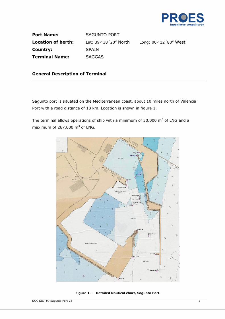
Port Name: SAGUNTO PORT
Location of berth: Lat: 39º 38´20” North Long: 00º 12´80” West
Country: SPAIN
Terminal Name: SAGGAS
General Description of Terminal
Sagunto port is situated on the Mediterranean coast, about 10 miles north of Valencia
Port with a road distance of 18 km. Location is shown in figure 1.
The terminal allows operations of ship with a minimum of 30.000 m3 of LNG and a
maximum of 267.000 m3 of LNG.
Figure 1.- Detailed Nautical chart, Sagunto Port.

DOC SIGTTO Sagunto Port V5 2
General Port Information
Geographic location
Latitude 39º 38' 20'' North
Longitude 00º 12' 80'' West
Winds
Frequent: SE
Extreme: NE ¼ E
Tides
The Sagunto Port and levels take as 0,00 level sea water in Alicante Vertical Datum, zero
CD.
Tidal Range, maximum: 0,65 m
Highest astronomical tide (HAT): 0,22 m
Lowest astronomical tide (LAT): -0,43 m
Harbour entrance conditions
Sagunto port is accessible from several routes; vessels are advised to approach through
the south side.
Only daylight berthing operation will be permitted. Unberthing operation will be permited
without daylight
Other traffic in the area (incoming or out-going) is not allowed during LNG operation,
therefore a minimum safety distance of 2 nautical miles must be observed between LNG
carriers and other vessel. No navigation is allowed at the basins when LNG carrier is
turning until is safely moored at the jetty.
Crossing manoeuvres at the inner or outer port are strictly prohibited.

DOC SIGTTO Sagunto Port V5 3
.
Figure 2.- Chart for vessel entrance. Sagunto Port.
Pilot Service
Pilotage is compulsory for all LNG carriers proceeding to Sagunto port. Pilot boarding
point is located 2 miles outside the port breakwater.

DOC SIGTTO Sagunto Port V5 4
All communication during incoming manoeuvres must be through VHF channel 16-12.
Anchoring
There is a designated Hazardous vessel area applicable for LNG. Please refer to figure 2.
Towage for manoeuvring
The use of tugs is obligatory for vessels going operation and the number of tugs to be
used will depend on vessel tonnage and metocean conditions.
Figure 3.- Nautical chart. LNG Jetty Location
Telephone Contact
Police: ............................................................................. 112
Ambulance: ...................................................................... 112
Fire: ................................................................................ 112
LNG Jetty
DOC SIGTTO Sagunto Port V5 5
Emergency coordination centre: .......................... +34963939573
Sagunto Port: ................................................... +34963939500
General Details of Terminal
Year LNG operations commenced: 2006
Name of Terminal operating company: SAGGAS
Name or job title of person to contact regarding terminal information:
Name or Title: Antonio Alegre
Address: www.saggas.com
Name of Port Authority: VALENCIA PORT
Name or job title of person to contact regarding port regulations:
Name or Title: Harbour Master
Address: Port Authority of Valencia
Avda. del Muelle del Turia, s/n
Valencia (Spain)
Tel:+34963939500 Fax: +34963939599 E-mail: [email protected]
Number of Berths: 1
Maximum size of vessel acceptable at Terminal:
Max Length*: 345,00 m Max Draught*: 12,00 m
Max Displacement*: 177.000 tonnes Max Beam*: 55,00 m
* Dimensions allows normal operation without restriction. Other figures would require
additional checking.
Dock water density: 1,027
Port Datum: Chart Datum
Please confirm that all depths, tidal heights and structure heights are all referenced to
the Port Datum: YES
LNG tank storage details:

DOC SIGTTO Sagunto Port V5 6
Nº of Tanks Capacity of Tanks
m³
Above ground or Below ground
Outside Diameter of Tank (metres)
Outside Height of Tank (metres)
Materials Used
3 x 150.000 m3 Above ground 76,50 m 54,31 m
Inner tank 9% Ni steel
Outer tank prestressed
concrete
For all loading / receiving Terminals Outer shell dimension
Regasification Vaporizers
Total Flow Tonnes / hr
Number of units / Type Remarks
200.000 Nm3/hr (per unit) 5 ORV
150.000 Nm3/hr 1 SCV
Details of each berth
Berth Name or Number: LNG Quay
Name of berth operator (if different):
Maximum size of vessel acceptable at berth: LOA*: 345,00 m
Draught*: 12,00
Max Beam*: 55,00 m
Maximum berthing displacement allowed: 177.000* tonnes
* Dimensions allows normal operation without restriction. Other figures would require
additional checking.
Depth of water alongside berth at zero rise of tide: 14 m below CD.
Type of berth: Quay
Normal side for berthing: Starboard
DOC SIGTTO Sagunto Port V5 7
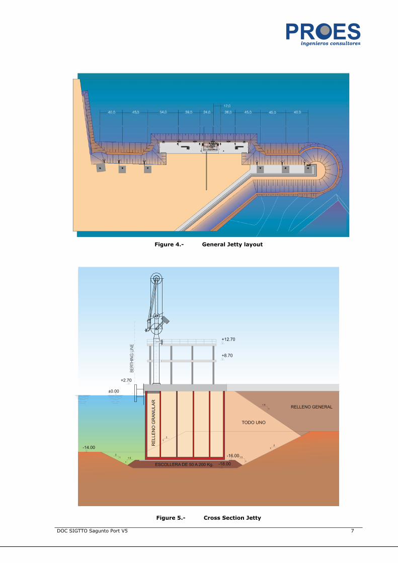
Figure 4.- General Jetty layout
Figure 5.- Cross Section Jetty

DOC SIGTTO Sagunto Port V5 8
Arrangement of Loading / Discharging Arms
(Looking to seaward)
1 2 3 4
Liquid or Vapour L L/V V L
Fuel Oil or Diesel
Other Liquid
Nitrogen
PERC fitted Yes Yes Yes Yes
QC/DC fitted Yes/manual Yes/manual Yes/manual Yes/manual
Nominal Diameter (cm/ins) 16” 16” 16” 16”
Flange standard ANSI B 16,5
150# RF
ANSI B 16,5
150# RF
ANSI B 16,5
150# RF
ANSI B 16,5
150# RF
If PERC fitted state distance or angle required to initiate:
ESD 1 Forward: 9,7 Aft: 9,7 Seawards: 5,6
ESD 2 Forward: 10,1 Aft: 10,1 Seawards: 6,2
Figure 6.- Loading arms location
DOC SIGTTO Sagunto Port V5 9
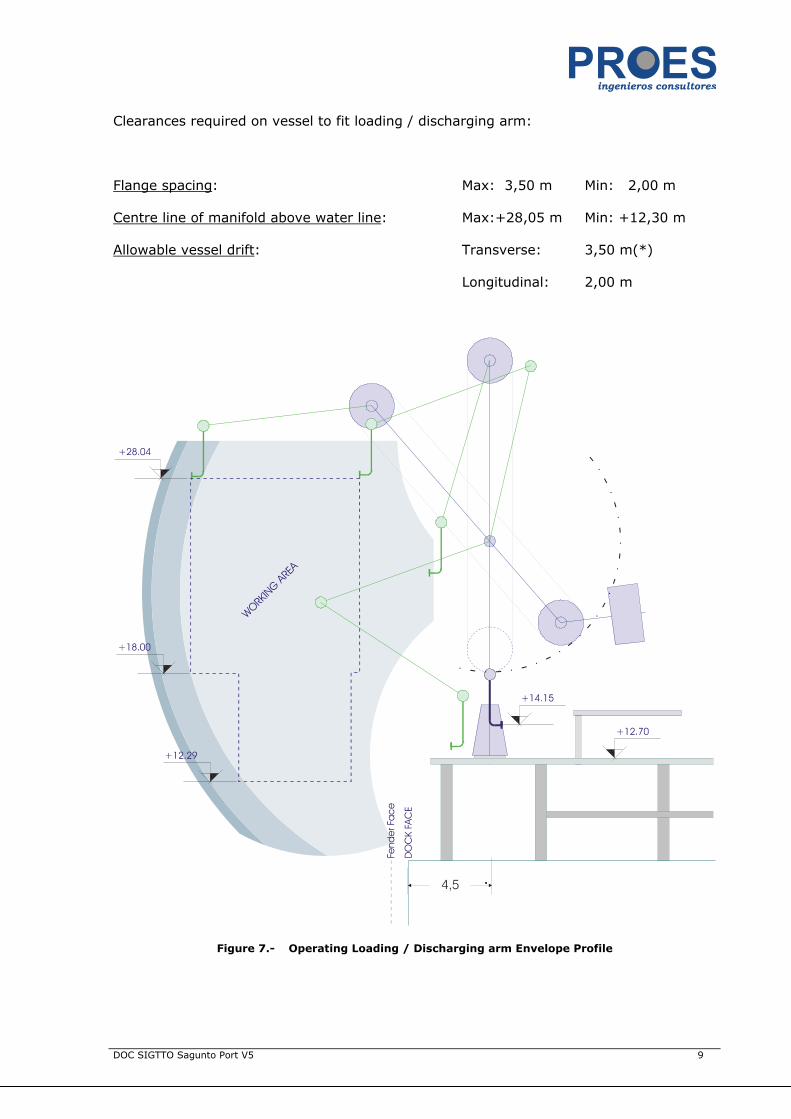
Clearances required on vessel to fit loading / discharging arm:
Flange spacing: Max: 3,50 m Min: 2,00 m
Centre line of manifold above water line: Max:+28,05 m Min: +12,30 m
Allowable vessel drift: Transverse: 3,50 m(*)
Longitudinal: 2,00 m
Figure 7.- Operating Loading / Discharging arm Envelope Profile

DOC SIGTTO Sagunto Port V5 10
Figure 8.- Operating Loading / Discharging arm Envelope
Details of terminal gangway arrangements
Type of gangway: Jetty is equipped with two electro hydraulic gangways located at both
sides of the unloading platform.
Manufacturer / Supplier: PROSERTEK
Working range at ship’s rail.
Height above Datum: Max: 19,50 Min: 7,00
Special arrangement required to attach gangway to vessel:
Removable rails No
Strengthened rails No
Strongback No
Other

DOC SIGTTO Sagunto Port V5 11
Distance between gangway and vapour return arm: Ford at 40 m. and aft at 45 m.
Figure 9.- Gangway location at jetty
Figure 10.- Plan Operating Gangway Envelope

DOC SIGTTO Sagunto Port V5 12
Details of umbilical connections between ship and shore
Number of connections: 2 ship to shore connector optical and electrical
Type of Service and Plug:
Core Service Distance from vapour
return L/D arm Forward Aftward
X ESD Optical 8,5 m X
X ESD electric 8,5 m X
ESD Pneumatic
X Phone Optical 8,5 m X
X Phone electric 8,5 m X
Tension Monitor Optical
Pneumatic Hose ESD Link NO
Is ESD primary link fitted? YES
Is ESD secondary link fitted? YES
Are test procedures carried out under:
Warm conditions X
Cold conditions X
Further comments on ship/shore communications, ship/shore links etc: appendix A

DOC SIGTTO Sagunto Port V5 13
Mooring Arrangements (Looking to seaward)
Forward ← Position of vapour return → Aft ward
Mooring massive blocks Ext 2 Ext 1 Inner Inner Ext 1 Ext 2
Number of Hooks 3 3 3 3 3 3
Rating (tonnes) 125 100 100 100 100 125
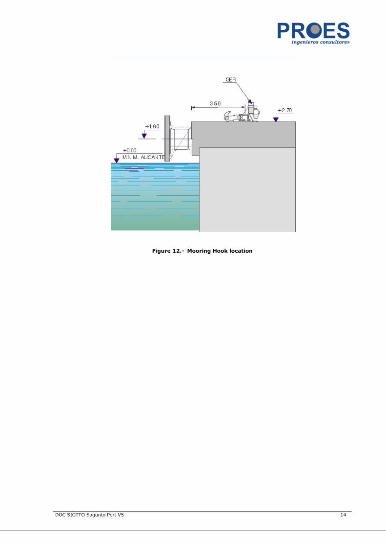
Height above datum (m) 2,7 2,7 2,7 2,7 2,7 2,7
Distance from vapour
return 168 128 83 117 162 202
Distance from berth face 46,8 46,8 46,8 46,8 46,8 46,8
Platform Ext Platform Platform Inner
Number of Hooks 3 3 3 3
Rating (tonnes) 100 100 100 100
Height above datum (m) 2,7 2,7 2,7 2,7
Distance from vapour
return 38 12 24 63
Distance from berth face 3,5 3,5 3,5 3,5
(Minimum) Mooring Requirements: (Example: For LNG Project Vessels)
Figure 11.- Mooring Arrangements
DOC SIGTTO Sagunto Port V5 14
Figure 12.- Mooring Hook location
DOC SIGTTO Sagunto Port V5 15
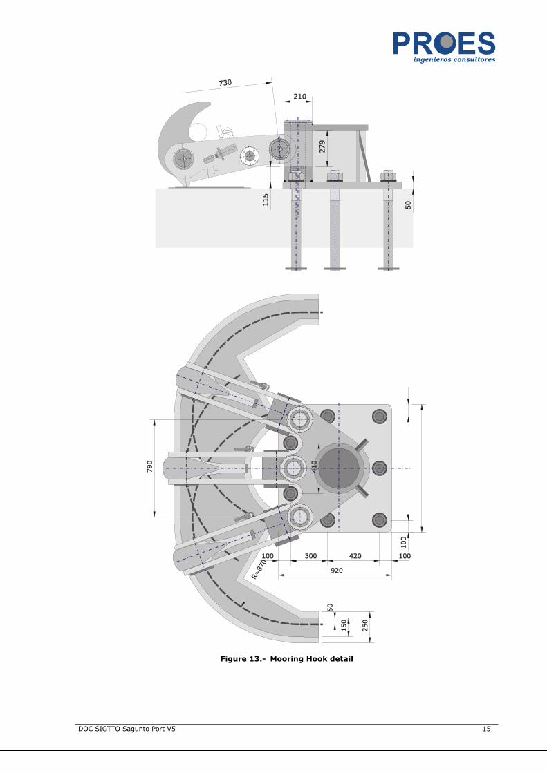
Figure 13.- Mooring Hook detail

DOC SIGTTO Sagunto Port V5 16
Drawing showing Mooring Arrangement for LNG Ship
Moorings Head Lines
For´d Breasts
For´d Springs
Aft Springs
Aft Breasts
Stern Lines
Total
Recommended mooring configuration. Vessel range over 200.000m3.
Number of lines 3 4 2 2 4 3 18
Figure 14.- Recommended mooring layout for unloading (vessels up to 140.500 m3)
Moorings Head Lines
For´d Breasts
For´d Springs
Aft Springs
Aft Breasts
Stern Lines
Total
Recommended mooring configuration. Vessel range within 90.000 m3 to 200.000m3.
Number of lines 2 3 2 2 3 2 14
Figure 15.- Recommended mooring layout for unloading (vessels up to 140.500 m3)
DOC SIGTTO Sagunto Port V5 17
Moorings Head Lines
For´d Breasts
For´d Springs
Aft Springs
Aft Breasts
Stern Lines
Total
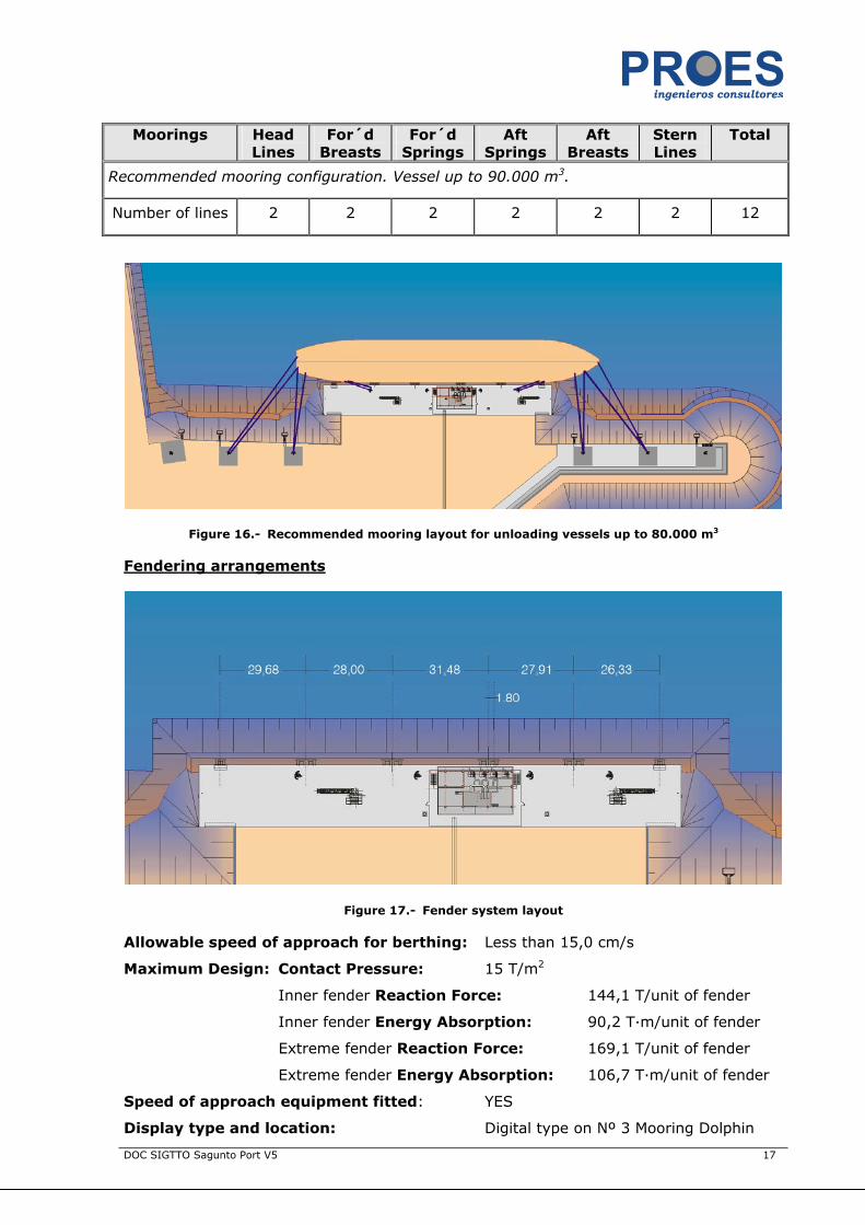
Recommended mooring configuration. Vessel up to 90.000 m3.
Number of lines 2 2 2 2 2 2 12
Figure 16.- Recommended mooring layout for unloading vessels up to 80.000 m3
Fendering arrangements
Figure 17.- Fender system layout
Allowable speed of approach for berthing: Less than 15,0 cm/s
Maximum Design: Contact Pressure: 15 T/m2
Inner fender Reaction Force: 144,1 T/unit of fender
Inner fender Energy Absorption: 90,2 T·m/unit of fender
Extreme fender Reaction Force: 169,1 T/unit of fender
Extreme fender Energy Absorption: 106,7 T·m/unit of fender
Speed of approach equipment fitted: YES
Display type and location: Digital type on Nº 3 Mooring Dolphin
DOC SIGTTO Sagunto Port V5 18
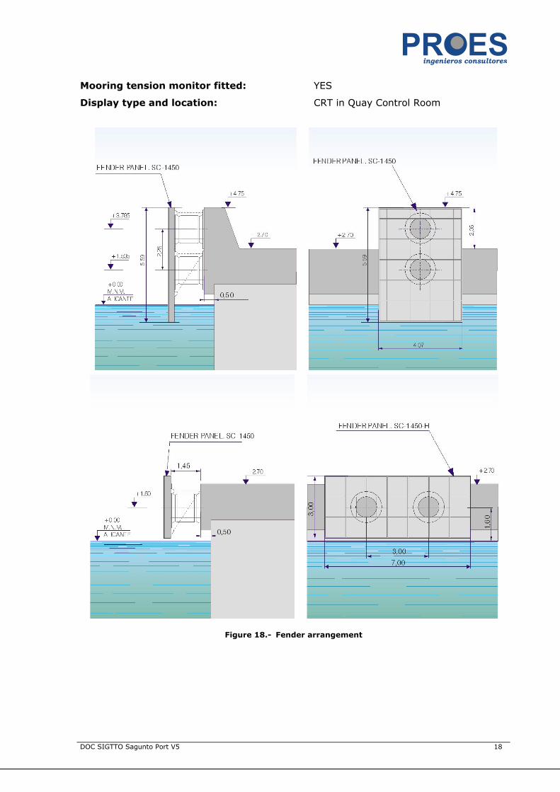
Mooring tension monitor fitted: YES
Display type and location: CRT in Quay Control Room
Figure 18.- Fender arrangement
DOC SIGTTO Sagunto Port V5 19
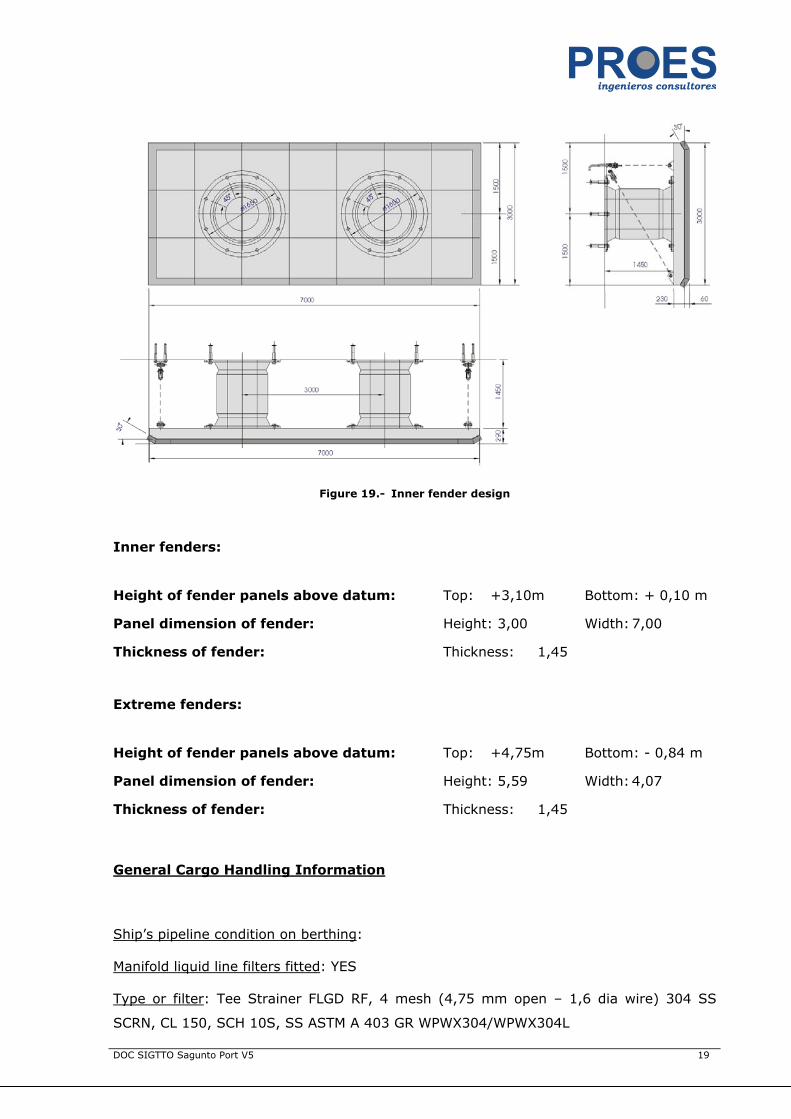
Figure 19.- Inner fender design
Inner fenders:
Height of fender panels above datum: Top: +3,10m Bottom: + 0,10 m
Panel dimension of fender: Height: 3,00 Width: 7,00
Thickness of fender: Thickness: 1,45
Extreme fenders:
Height of fender panels above datum: Top: +4,75m Bottom: - 0,84 m
Panel dimension of fender: Height: 5,59 Width: 4,07
Thickness of fender: Thickness: 1,45
General Cargo Handling Information
Ship’s pipeline condition on berthing:
Manifold liquid line filters fitted: YES
Type or filter: Tee Strainer FLGD RF, 4 mesh (4,75 mm open – 1,6 dia wire) 304 SS
SCRN, CL 150, SCH 10S, SS ASTM A 403 GR WPWX304/WPWX304L

DOC SIGTTO Sagunto Port V5 20
Bulk loading/discharging rate permitted: Vapour: 12.000 m3/h/total
(4.000m3/h /arm)
Liquid: 12.000 m3/h/arm
Average liquid flow rate available: 4.000 m3/h/arm
Max. Allowable volume of return gas: 12.000 m3/h/arm
Temperature or return gas: -140ºC
Max. Allowable cargo pressure on arrival: 1,17 bar
Ship’s stores and supplies
Is ship’s storing allowed? YES
What is location of stores loading platform on berth:
Availability of supplies YES/NO Line size Quantity available
Delivery Rate m3/H
Liquid nitrogen YES 2”. piggy back on vapour return arm
By truck 15 m3/h
Drinking water NO*
Fuel oil NO*
Diesel oil NO*
Other
* Port supplies bunkering and other general services. Bunkering is not allowed during
unloading operations
Vessel Operation conditions
Tugboats
Berthing – Minimum number of tugs required: 3/4
Unberthing – Minimum number of tugs required: 3/4
Tug fleet assigned will depend on vessel capacity and equipment.
TUGS: 4 tugs of 2.236 h.p.- 2.400 h.p. available.
DOC SIGTTO Sagunto Port V5 21
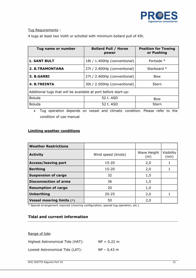
Tug Requirements :
4 tugs at least two Voith or schottel with minimum bollard pull of 45t.
Tug name or number Bollard Pull / Horse power
Position for Towing or Pushing
1. SANT BULT 18t / 1.400Hp (conventional) Portside *
2. B.TRAMONTANA 27t / 2.400Hp (conventional) Starboard *
3. B.GARBI 27t / 2.400Hp (conventional) Bow
4. B.TREINTA 30t / 2.500Hp (conventional) Stern
Additional tugs that will be available at port before start-up:
Boluda 52 t. ASD Bow
Boluda 52 t. ASD Stern
• Tug operation depends on vessel and climatic condition. Please refer to the
condition of use manual
Limiting weather conditions
Weather Restrictions
Activity Wind speed (knots) Wave Height
(m) Visibility
(nm)
Access/leaving port 15-20 2,0 1
Berthing 15-20 2,0 1
Suspension of cargo 32 1,5
Disconnection of arms 36 1,5
Resumption of cargo 20 1,0
Unberthing 20-25 2,0 1
Vessel mooring limits (*) 50 2,0 * Special arrangement required (mooring configuration, special tug operation, etc.)
Tidal and current information
Range of tide:
Highest Astronomical Tide (HAT): NP + 0,22 m
Lowest Astronomical Tide (LAT): NP – 0,43 m

DOC SIGTTO Sagunto Port V5 22
Are tides diurnal or semidiurnal: Semidiurnal
Currents: Quay is equipped with current meter that registers intensity and direction
Normal current alongside berths: worthless
Winds: Quay is equipped with a meteorological station that records intensity and
direction
Prevailing winds: E & W
Downtime expected: Below 5 days / year
Pilotage
Applicable sailing directions/Charts: Charts: 481, 4812.
Sea pilot boarding position: At the waiting area.
Harbour Pilot boarding position (if required): At breakwater
Distance – sea pilot to berth: Aprox. 2,5 nautical miles.
Arrival arrangements: ETA confirmation 24 hours before arrival
Communication channel: 16-12
Number of pilots boarded: 1 (before June 2006 2 pilots on board are required)
Traffic surveillance / monitoring service available: No
Other comments:

DOC SIGTTO Sagunto Port V5 23
Port Entry/Departure policy
Daylight/24 hours: Daylight
Special rules for LNG vessels YES See COU manual
Traffic separation scheme NO
Escorting craft YES See COU manual
Any restrictions for entering/departing
YES See COU manual
Disaster Protection Information
On or around berth:
Drypowder YES
Water curtain YES
Gas detection system YES
Oil fence around ship NO
Buoy markers NO
Standby vessels YES Suggested
Fire-fighting support vessel YES Connection provided
Figure 20.- Firefighting equipment. Monitor tower location

DOC SIGTTO Sagunto Port V5 24
Terminal LNG Production/Demand information (confirmar)
Year Production (b.c.m) Demand (b.c.m.) Ship Visits
2005
2006 6,6 4,0 63
2007 6,6 4,0 97
2008 6,6 4,97 97
2009 8 4,96 100
Aerial view of port
Figure 21.- Aerial view of Sagunto Port
SAGGAS FACILITIES

DOC SIGTTO Sagunto Port V5 25
LNG Carriers regularly calling al Terminal
Ship Name / Type Tank Type Berth Used Coming From
Construction Projects
Please add information here on approved projects expected to be completed within the
next three years.
1. Improvements to existing waterfront? No
2. New waterfront facilities? No
3. Improvements to existing storage tank?
4. New storage tanks? Yes (4th)
5. Others?
APPENDIX A:
SHIP-SHORE COMMUNICATION SISTEM DATA
APPENDIX A
SHIP-SHORE COMMUNICATION SISTEM DATA
Manufacturer/interconnection sistem model: Sea Technik NFI, compatible with the
Sumitomo–Furukawa system.
Optical fibre interchanged signals: 2 audio, 2 emergency shut down.
Optical fibre cable & signals in connector grouping description: Channel 1, vessel-
land modulated and multiplex audio; channel 2, land-vessel modulated and multiplex
audio; channel 3, no volt connection for vessel initiated emergency shut down; channel
4, no volt connection for land initiated emergency shut down; channels 5 and 6, ship-
land and land-ship extra signal reserve.
Connector type and optical fibre cable: Six channels Furukawa connector. Channels
are placed circularly in the connector, up down and anticlockwise numerated.(fig. 1)
Electrical wire interchanged signals: Communications panel, and 2 for emergency
shut down, these are no volt connections, usually closed system, turn into broken circuit
in case of emergency, vessel or land initiated respectively.
Electrical wire and connector signals grouping description: Pyle National 37 pins
connector EX’d Cenelec certified. Pairs 3-4, 5-6, 7-8, 9-10 lead communication signals.
Pins nº 13-14 are no volt connections, usually closed that open in case of emergency
(land emergency). Pins nº 15-16 are no volt connections, usually closed, that open in
case of emergency (vessel emergency). Pin nº rises as follows: up down and left-hand
spiral from without inwards. (fig 2)
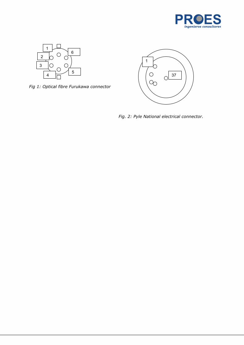
Fig 1: Optical fibre Furukawa connector
Fig. 2: Pyle National electrical connector.
1
2
3
4 5
6
1
37

CONTENTS
GENERAL DESCRIPTION OF TERMINAL ................................................1
GENERAL PORT INFORMATION ............................................................2
GEOGRAPHIC LOCATION ................................................................................................................2 WINDS....................................................................................................................................2 TIDES .....................................................................................................................................2 HARBOUR ENTRANCE CONDITIONS....................................................................................................2 PILOT SERVICE ..........................................................................................................................3 ANCHORING ..............................................................................................................................4 TOWAGE FOR MANOEUVRING ..........................................................................................................4 TELEPHONE CONTACT...................................................................................................................4
GENERAL DETAILS OF TERMINAL.........................................................5
REGASIFICATION VAPORIZERS ........................................................................................................6 DETAILS OF EACH BERTH ...............................................................................................................6 ARRANGEMENT OF LOADING / DISCHARGING ARMS ...............................................................................8
DETAILS OF TERMINAL GANGWAY ARRANGEMENTS..........................10
DETAILS OF UMBILICAL CONNECTIONS BETWEEN SHIP AND SHORE ............................................................12 MOORING ARRANGEMENTS (LOOKING TO SEAWARD)............................................................................13
DRAWING SHOWING MOORING ARRANGEMENT FOR LNG SHIP ........16
FENDERING ARRANGEMENTS.........................................................................................................17 GENERAL CARGO HANDLING INFORMATION .......................................................................................19 SHIP’S STORES AND SUPPLIES.......................................................................................................20
VESSEL OPERATION CONDITIONS .....................................................20
TUGBOATS..............................................................................................................................20 LIMITING WEATHER CONDITIONS ...................................................................................................21
TIDAL AND CURRENT INFORMATION.................................................21
PILOTAGE...............................................................................................................................22 PORT ENTRY/DEPARTURE POLICY ...................................................................................................23 DISASTER PROTECTION INFORMATION.............................................................................................23 TERMINAL LNG PRODUCTION/DEMAND INFORMATION (CONFIRMAR) .........................................................24
AERIAL VIEW OF PORT ......................................................................24
LNG CARRIERS REGULARLY CALLING AL TERMINAL ..............................................................................25
CONSTRUCTION PROJECTS ................................................................25
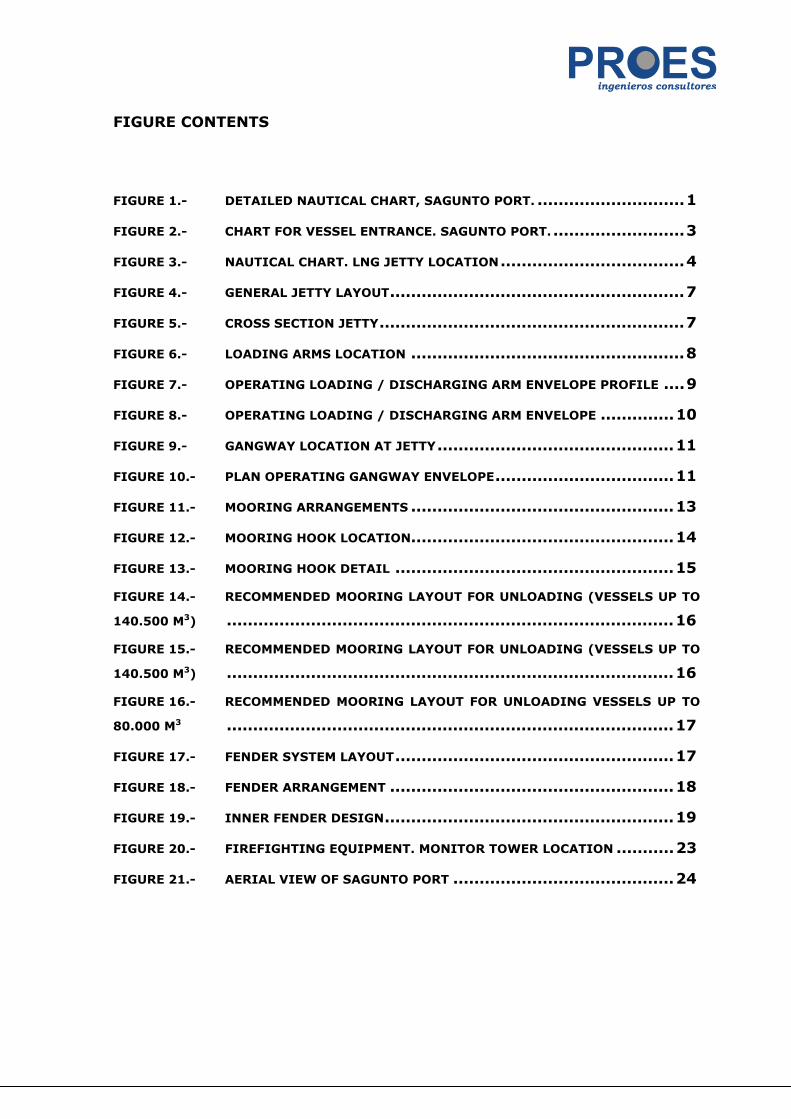
FIGURE CONTENTS
FIGURE 1.- DETAILED NAUTICAL CHART, SAGUNTO PORT. ............................1
FIGURE 2.- CHART FOR VESSEL ENTRANCE. SAGUNTO PORT. .........................3
FIGURE 3.- NAUTICAL CHART. LNG JETTY LOCATION...................................4
FIGURE 4.- GENERAL JETTY LAYOUT........................................................7
FIGURE 5.- CROSS SECTION JETTY..........................................................7
FIGURE 6.- LOADING ARMS LOCATION ....................................................8
FIGURE 7.- OPERATING LOADING / DISCHARGING ARM ENVELOPE PROFILE ....9
FIGURE 8.- OPERATING LOADING / DISCHARGING ARM ENVELOPE ..............10
FIGURE 9.- GANGWAY LOCATION AT JETTY.............................................11
FIGURE 10.- PLAN OPERATING GANGWAY ENVELOPE..................................11
FIGURE 11.- MOORING ARRANGEMENTS ..................................................13
FIGURE 12.- MOORING HOOK LOCATION..................................................14
FIGURE 13.- MOORING HOOK DETAIL .....................................................15
FIGURE 14.- RECOMMENDED MOORING LAYOUT FOR UNLOADING (VESSELS UP TO
140.500 M3) .....................................................................................16
FIGURE 15.- RECOMMENDED MOORING LAYOUT FOR UNLOADING (VESSELS UP TO
140.500 M3) .....................................................................................16
FIGURE 16.- RECOMMENDED MOORING LAYOUT FOR UNLOADING VESSELS UP TO
80.000 M3 .....................................................................................17
FIGURE 17.- FENDER SYSTEM LAYOUT.....................................................17
FIGURE 18.- FENDER ARRANGEMENT ......................................................18
FIGURE 19.- INNER FENDER DESIGN.......................................................19
FIGURE 20.- FIREFIGHTING EQUIPMENT. MONITOR TOWER LOCATION ...........23
FIGURE 21.- AERIAL VIEW OF SAGUNTO PORT ..........................................24