LOAD FACTOR RESISTANCE DESIGN - Louisiana … Kim.pdf · TEST LOAD = > USE FACTORED LOAD FOR BENTS...
38
LOAD FACTOR RESISTANCE DESIGN HOW CONSTRUCTION ACTIVITIES & SPECIFICATIONS ARE AFFECTED LOUISIANA TRANSPORTATION CONFERENCE 2009 Kim Martindale Garlington, P.E. LADOTD Pavement and Geotechnical Engineer LRFD
Transcript of LOAD FACTOR RESISTANCE DESIGN - Louisiana … Kim.pdf · TEST LOAD = > USE FACTORED LOAD FOR BENTS...

LOAD FACTOR RESISTANCE DESIGN
HOW CONSTRUCTION ACTIVITIES&
SPECIFICATIONS ARE AFFECTED
LOUISIANA TRANSPORTATION CONFERENCE
2009Kim Martindale Garlington, P.E.
LADOTD Pavement and Geotechnical Engineer
LRFD

LRFD IMPLEMENTATION
STARTED IN GEOTECHNICAL DESIGN SEPTEMBER 2007
MAJOR CHANGE
HOW DOES IT MAKE YOU FEEL???

Mad enough to break something!
Commit violence in the workplace?

THE OLD STAND BY
THING ARE GOING DOWN THE YOU KNOW WHAT!!!!

CHANGES
Many are already implemented
MORE BORINGS AND EXPLORATION DATA
MORE AND NEW LOAD TESTS
NEW INFORMATION ON LOAD TEST DATA TABLES
MORE MONITOR PILES DURING PRODUCTION PILE DRIVING
SECTION 804 AND 814 – SPECIFICATION CHANGES
DYNAMIC MONITORING - SPECIFICATION CHANGES
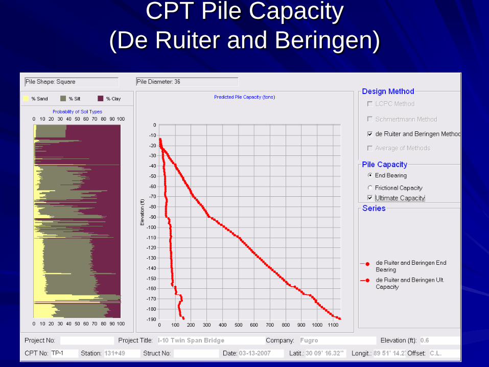
CPT Pile Capacity (De Ruiter and Beringen)
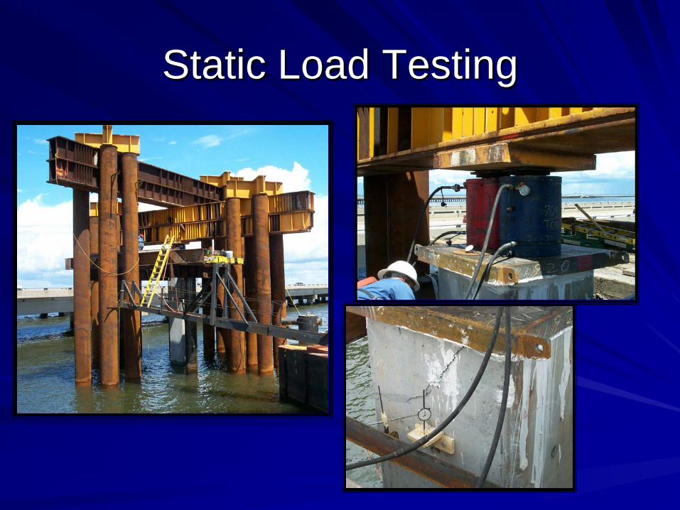
Static Load Testing

Static Load Test Results: TP-1

Dynamic Load Test (Pile Driving Analyzer - PDA)

CHANGES IN PLANS
NOTES ON BRIDGE PLANS AND FOUNDATION SHEETS
CHANGES IN THE PILE DATA TABLES THEMSELVES
SIMPLE STRUCTURES – FEW TEST PILES - LOW VARIETY IN PILE TYPES AND LOADS
COMPLEX STRUCTURES – MANY BENTS, PILE TYPES, VARIETY IN PILE LOADS, MANY TEST PILES AND MONITOR PILES

065-06-0040 - GRAND BAYOU BRIDGE - LA 20
BENT
FACTORED LOAD (TONS) RESISTANCE FACTOR
SCOUR ZONE
RESISTANCE (TONS)
TARGET PILE
CAPACITY (TONS)
ULTIMATE PILE
CAPACITY (TONS)
PLAN PILE LENGTHS
COMP TENCOMP.
COHESIVENON
COHESIVE
1 94 N/A 0.80 0.80 70 188 190 93.00
2 94 N/A 0.80 0.80 70 188 190 93.00
3 94 N/A 0.80 0.80 70 188 190 93.00
4 94 N/A 0.80 0.80 70 188 190 93.00
5 94 N/A 0.80 0.80 70 188 190 93.00
6 94 N/A 0.80 0.80 70 188 190 93.00
NOTE IN PLANS: TEST PILE LOADED TO FAILURE OR 180 TONS
ie: (FACTORED LOAD / RF) x 1.5 = TEST PILE LOAD SPECIFIED
94/0.8 x 1.5= 176 TONS SO USED 180 TONS
TARGET CAPACITY = FACTORED LOAD / RF + SCOUR ZONE RESISTANCE
TARGET CAPACITY = 94 / 0.8 + 70 = 188 TONS
FACTORED LOAD (TONS) RESISTANCE FACTOR
SCOUR ELEV.
SCOUR ZONE
RESISTANCE
(TONS)
TARGET PILE CAP.
(TONS)
ULT PILE CAP.
(TONS)
COMP. TEN
COMP.
TEN.COHESIVE
NON COHESIVE
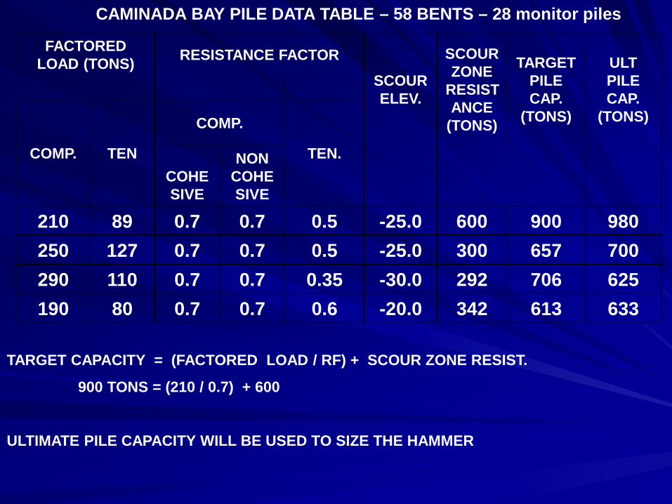
210 89 0.7 0.7 0.5 -25.0 600 900 980250 127 0.7 0.7 0.5 -25.0 300 657 700290 110 0.7 0.7 0.35 -30.0 292 706 625190 80 0.7 0.7 0.6 -20.0 342 613 633
TARGET CAPACITY = (FACTORED LOAD / RF) + SCOUR ZONE RESIST.
900 TONS = (210 / 0.7) + 600
ULTIMATE PILE CAPACITY WILL BE USED TO SIZE THE HAMMER
CAMINADA BAY PILE DATA TABLE – 58 BENTS – 28 monitor piles

TEST PILE DATA – 36” PPC PILES
Test Pile No. Tip Elev. Bottom Casing Elev.
Test Load (tons) (Comp.)
1 -60.0 -25.0 5402 -130.0 -34.0 6253 -145.0 -60.0 6254 -160.0 -79.0 5805 -140.00 -50.0 5806 -125.00 -30.0 6257 -65.00 -20.0 410
TEST LOAD = > USE FACTORED LOAD FOR BENTS REPRESENTED
EX: Test pile #1 factored load = 250 tons
Test load = (250 / 0.7) X 1.5 = 535 tons - Use 540 as TEST LOAD
TP#7 Test load = (190 / 0.7) X 1.5 = 407 tons - Use 410 tons as TEST LOAD
TP#3 Test Load = (290 / 0.7) X 1.5 = 621 tons – Use 625 tons as TEST LOAD
CAMINADA BAY BRIDGE TEST PILE DATA TABLE


SECTION 804
PROPOSED SPECIFICATION CHANGES
PULLED FROM 450-10-0108 AND APPROVED FOR THAT PROJECT
GEOTECHNICAL CONSULTANT PERFORMING THE FIELD MONITORING WORK FOR THE DEPARTMENT
This may be to some like pulling teeth but bear with us as we are learning also!!!

SECTION 804.05 - PILE DRIVING SYSTEM SUBMITTAL AND APPROVAL.
The geotechnical engineer will evaluate the Pile Installation Plan for conformance with the plans and specifications. Within 20 calendar days after receipt of the Pile installation Plan, the project engineer will notify the contractor of any additional information required and/or changes that may be necessary in the opinion of the geotechnical engineer to meet the plans and specification requirements.

804.05 PILE DRIVING SYSTEM SUBMITTAL AND APPROVAL.(b) Driven Pile Installation Plan:
(3) Drivability analyses using the wave equation method (WEAP)
The wave equation analysis shall consider all critical conditions to determine the estimated driving resistance (blows per foot), maximum tensile and compressive stresses during driving, and end-of-drive conditions. Splices, casing used, pilot holes, jetting, and other driving methods, if proposed, shall be analyzed. Sufficient analyses shall be performed to verify driving conditions at various locations, if the soil conditions change within the project area.

DELETED
ALTERNATE HAMMER APPROVAL METHOD
DELETED TABLE 804-1

SECTION 804.05 - SYSTEM SUBMITTALS
(c) Pile Driving Equipment Approval: Approval of the contractor's pile driving equipment will be based on the wave equation analysis computer program (FHWA WEAP87 or newer version) and as required elsewhere in this subsection. The contractor is responsible to provide the analysis and results to the Geotechnical Engineer for review for each pile type and size required in the plans. Approval of the pile driving system by the Geotechnical Engineer does not relinquish the contractor's responsibility from driving the piles to the required pile tip elevation without damage.


Section 804.06 Pile Driving Equipment
(b) Drive System Components
(3) Pile Cushion:
The pile cushion shall be stored to prevent wetting. Wet or cracked cushions shall not be used. The minimum pile cushion thickness shall be established with the WEAP analysis and modified as necessary by the engineer based on field observation and/or dynamic monitoring results.

NEW TECHNOLOGY
ELECTRIC CONE PENETROMETER

SECTION 804.07 PREPARATION FOR INSTALLATION OF DRIVEN PILES
(a) SITE PREPARATION
(5) Cone Penetrometer Test (CPT) Probings: The contractor shall make arrangements with the geotechnical engineer to have the CPT probings taken at least 30 calendar days prior to driving test piles or indicator piles. When necessary, the contractor shall provide equipment to assist in moving the Cone Penetrometer Test truck around the site. The site for the probings shall be level as directed. The contractor shall assist the department in surveying the location and elevation of the CPT probing locations.

Section 804.08 – CONSTRUCTION REQUIREMENTS
(a) Preboring
Prebored holes shall have a maximum diameter of 80 percent of the minimum pile dimension unless written approval to do otherwise is received from the geotechnical engineer.
(b) Jetting: Geotechnical Engineer more involved in jetting plan

SECTION 804.08– CONSTRUCTION REQUIREMENTS
(g) Pile Driving Stresses: The piles shall be driven in a manner as not to exceed the maximum driving stresses allowed in the Pile Driving Contractor Association’s “Design and Construction of Driven Pile Foundations”……….
(Eliminated Table 804-2)
The plans shall indicate if the allowable tensile driving stress of precast- prestressed concrete piles shall be computed for corrosive environments. Pile driving criteria may be provided by the Geotechnical Engineer to maintain pile driving stresses within the maximum allowable driving stresses.

High TSX
Plywood Added
Lower Stress

SECTION 804.08– CONSTRUCTION REQUIREMENTS
(h) Extent of Driving:
Approval from the geotechnical engineer shall be required to terminate pile driving above the plan tip elevation or order list pile tip elevation. Piles shall be driven to the plan tip elevation or the order list pile tip elevation in accordance with these specifications. The following requirements shall be used to evaluate satisfactory pile penetration and pile bearing capacity.

SECTION 804.09 – UNSATISFACTORY PILESAny pile found to be unacceptable due to internal defects, by improper driving, driven out of proper location, or driven below required elevation shall be corrected at no direct pay by one of the following methods approved by the project engineer after consultation with the geotechnical engineer:
(e) Cracks in concrete piles shall be corrected as follows:
(3) Concrete piles with minor hairline surface cracks will not be cause for rejection or repair provided no change in the crack condition occurs during driving. This is not applicable to corrosive environments where salt water, water with high salinity, or existence of chemicals may reduce the pile service life.

804.10 DETERMINATION OF PILE BEARING CAPACITY.
The pile bearing capacity is the pile resistance obtained during the end-of-driving or pile restrike. The pile bearing capacity determination shall be made by use of the Wave Equation, Dynamic Load Testing (PDA), or the Test Pile Loading Results as specified in the plans. The Dynamic Formula may be used only with the geotechnical engineer’s approval.

804.10 DETERMINATION OF PILE BEARING CAPACITY.
(a) Dynamic Formula
If the end of driving capacity is not shown on the plans the required pile bearing capacity shall be 3 times the maximum load specified in the plans.
DYNAMIC FORMULA HAS NOT CHANGED!!

804.11 FIELD TESTING PILES.
(b)Test Piles: If the test pile is different than the anticipated permanent pile, prior approval must be received from the geotechnical engineer.
(e) Pile Restrikes: Restrike times may be adjusted at the geotechnical engineer’s discretion after a review of initial driving conditions as well as available restrike or load test results.

SECTION 804.11 – FIELD TESTING OF PILES
(9)Loading Permanent Piles:
Permanent piles shall be loaded to failure or until a load equal to the test load plus any additional soil resistance required by the Geotechnical Engineer.
(10)Dynamic Load Test:
This work consists of assisting the Department in obtaining dynamic measurements with the geotechnical engineer's Pile Driving Analyzer (PDA)

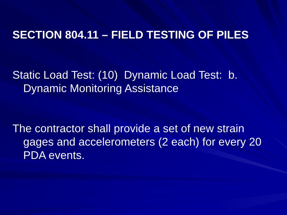
SECTION 804.11 – FIELD TESTING OF PILES
Static Load Test: (10) Dynamic Load Test:
a. Dynamic Monitoring Scheduling:
The project engineer will notify the geotechnical engineer to confirm that the pile and all associated pile driving equipment are on site, have been inspected and assembled, and are ready for driving operations at least 24 hours prior to dynamic monitoring.

STRAIN GAGES AND ACCELEROMETERS
MAJOR COST TO PURCHASE AND RECALIBRATE
SECTION 804.11 – FIELD TESTING OF PILES
Static Load Test: (10) Dynamic Load Test: b. Dynamic Monitoring Assistance
The contractor shall provide a set of new strain gages and accelerometers (2 each) for every 20 PDA events.

WE ALL KNOW TIME IS MONEY???

804.12 MEASUREMENT
(l) Dynamic Monitoring:
Contractor shall reimburse the geotechnical engineer for the expenses associated with the delays caused by the contractor at an hourly rate established in the contract, if the delay is more than one hour.

THANKS FOR LISTENING
PLEASE LET ME OR MY STAFF KNOW OF ANY COMMENTS