LNG Cargo Operating Manual
257
3J Cargo Operating Manual LNG AL WOSAIL (H1440) 1 st draft / 2004.10.29
-
Upload
asif-siddiqui -
Category
Documents
-
view
1.477 -
download
170
Transcript of LNG Cargo Operating Manual

8/12/2019 LNG Cargo Operating Manual
http://slidepdf.com/reader/full/lng-cargo-operating-manual 1/257
3J
Cargo Operating ManualLNG AL WOSAIL (H1440)
1 st draft / 2004.10.29

8/12/2019 LNG Cargo Operating Manual
http://slidepdf.com/reader/full/lng-cargo-operating-manual 2/257

8/12/2019 LNG Cargo Operating Manual
http://slidepdf.com/reader/full/lng-cargo-operating-manual 3/257

8/12/2019 LNG Cargo Operating Manual
http://slidepdf.com/reader/full/lng-cargo-operating-manual 4/257
8/12/2019 LNG Cargo Operating Manual
http://slidepdf.com/reader/full/lng-cargo-operating-manual 5/257

8/12/2019 LNG Cargo Operating Manual
http://slidepdf.com/reader/full/lng-cargo-operating-manual 6/257

8/12/2019 LNG Cargo Operating Manual
http://slidepdf.com/reader/full/lng-cargo-operating-manual 7/257
3J LNG AL WOSAIL Cargo Operating Manual
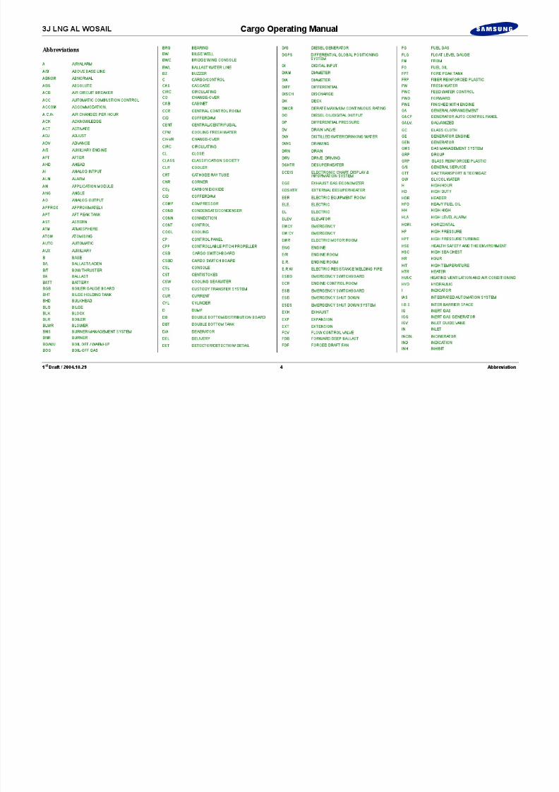
1 st Draft / 2004.10.29 6 Abbreviation
VL VERY LOW
VPR VAPOUR
VRC VALVE REMOTE CONTROL
V/V VALVE
WTR WATER
W/H WHEELHOUSE
WHC WHEELHOUSE CONSOLE
WIND WINDING
WO WASTE OIL
WS WORKSHOP
WU WARM UP
X CROSS/TRANSMITTER

8/12/2019 LNG Cargo Operating Manual
http://slidepdf.com/reader/full/lng-cargo-operating-manual 8/257
3J LNG AL WOSAIL Cargo Operating Manual
1 st Draft / 2004.10.29 Part 1 Design Concept of the Vessel
Part 1 : Design Concept of the Vessel1.1 Principal Particulars...........................................................................1 - 1
1.1.1 Principal Particulars of the Ship ........... ............. ............ ......... 1 - 1 1.1.2 Principal Particulars of Cargo Machinery...............................1 - 3 1.1.3 Maker List...............................................................................1 - 5 1.1.4 General Arrangement..............................................................1 - 7 1.1.5 Tanks and Capacity Plan.........................................................1 - 8
1.2 Classification, Rules and Regulations..............................................1 - 10 1.3 Design Concept of the Cargo System ........... ............ ........... ............ 1 - 14
1.3.1 Cargo Containment System Principle..... ............ ............ ...... 1 - 14 1.3.2 Membrane Cargo Containment.............................................1 - 22 1.3.3 Deterioration or Failure ............ ............ ............ ............ ........ 1 - 24
1.4 Hazardous Areas and Gas Dangerous Zone.....................................1 - 26
Part 1Design Concept of the Vessel

8/12/2019 LNG Cargo Operating Manual
http://slidepdf.com/reader/full/lng-cargo-operating-manual 9/257
8/12/2019 LNG Cargo Operating Manual
http://slidepdf.com/reader/full/lng-cargo-operating-manual 10/257

8/12/2019 LNG Cargo Operating Manual
http://slidepdf.com/reader/full/lng-cargo-operating-manual 11/257

8/12/2019 LNG Cargo Operating Manual
http://slidepdf.com/reader/full/lng-cargo-operating-manual 12/257

8/12/2019 LNG Cargo Operating Manual
http://slidepdf.com/reader/full/lng-cargo-operating-manual 13/257

8/12/2019 LNG Cargo Operating Manual
http://slidepdf.com/reader/full/lng-cargo-operating-manual 14/257

8/12/2019 LNG Cargo Operating Manual
http://slidepdf.com/reader/full/lng-cargo-operating-manual 15/257
3J LNG AL WOSAIL Cargo Operating Manual
1 st Draft / 2004.10.29 1 - 7 Part 1 Design Concept of the Vessel
1.1.4 General Arrangement
AIRDRAUGHT(apprx. 50MA/B)
UP
DNTOE/R
UP
UP
UP
UP
VENT. VEN T.CRO SS VENT .
VENT. VEN T.CRO SSVENT .
UP
*
HL
HL
EL.TRUNK
ESCAPETRUNKFOR ECR
ELEVAT OR W . C
AIR HANDLINGUNITROO M
OXY.RM
ACE.RM
HYD. PO WERUNIT ROOM
*
**
*
*
*
*
*
*
*
*
*
*
*
*
LOBBY
PAINT STORE
DECKSTORE
MEATROOMVEGET.
ROOM
DAIRYROOM
LOBBY
FISHROOM
S T O R E
W.C
DRY PRO V.STORE
*
DUMBWAITER
L O C K E R
WORKERSCABIN(6 P) SAFETY
EQUIP.ROOM
CRE W'SCHA NGROOM FIRE
CONTRO LSTATION
NO 1CARGO
SWITCHBOARDROOM
OFFICERS'CHANG ING ROOM
NO 2 .CARGO
SWITCHBOARDROOM
ENGINE CASI NG
CO2RELEASE
CHE M-ICAL
STORE
OILGREASESTORE
LOBBY
LO-BBY
W / B
W/B
W / B
W / T
MIDSHIP SECTION
UPPER DECK
PROFILE
A.P. T .
A.P.
C.L.
N O. 3 W. B. T
. ( P & S )
N O. 2 W. B. T
. ( P & S )
N O. 1 W
. B. T. ( P &
S )
A.P.
B.L.
C O F F E R D A M
C O F F E R D A M
C O F F E R D A M
C O F F E R D A M
C O F F E R D A M
NO.3 TRUNK NO.2 TRUNK NO.1 TRUNK
C.W.T
S I D E T AN G E N T LI N E
D.L.W.L.EM'CYEXIT
ENGINE ROOM
NO. 4 CARGO TANK NO. 3 CARGO TANK NO. 2 CARGO TANK NO. 1 CARGO TANK
DECK STORE
NO.4 TRUNK
ELEC.MOTORROOM
CARGOMACH.ROOM
CARGOMACH.ROOM
ELEC.MOTORROOM
FS :800
2900
F W D W
. B . T . ( P &
S )
F . W . T . ( P &
S )
D I S T . W
. T . ( P &
S )
2900
FWD.PUMPRM.
N O. 4 W. B. T
. ( P & S )
13600 44000 2650 2900 2650
FS :800
20800
N O. 2 H
. F. O. T. ( S )
NO.1H.F.O.SETT.T.(S)
LOWSULPHURH.F.O.T.(P)
D . O . S
T O R
.
T . ( S )
E / R W. B. T
. ( P & S ) H.F.O.
OVERFLOWT.(P)
NO.2H.F.O.SETT.T.(S)
D.O.SERV.T.(S)
10 20 30 40 50 60 70
10 20 30 40 50 60 70
130 140150
N O . 1 H
. F . O . T . ( C )
8090 100 110 120
130 140 150
3080 3075 3250 3225 3250 3225 2990 2925
40035 45475 45475 29835
80 90 100 110 120
B.WS/TL.ODRAIN TK.
MAINL.OSUMPTK B.W B.W
B.W B.W B.W
685
AIRDRAUGHT(apprx. 50MA/B)
PRINCIPAL PARTICULARS
Length Overall 283.0 mLength Between Perpendiculars 270.0 mBreadth (mld) 43.4 mDepth (mld) 26.0 mDraft Design (mld) 11.4 m Scantling (mld) 12.4 m
SERVICE SPEED 20.5 Knots at MCR with 15% S.M.
MAIN ENGINE TYPE : MARINE STEAM TURBINEMCR : 39,500 SHP x 90.0 RPM
CLASSIFICATION
American Bureau of Shipping : A1, Liquefied gas carrier, Ship type 2G,(Membrane Tank, Maximum Pressure 25 kPaG andMinimum Temperature -163 , Specific Gravity 500 kg/m 3)SH-DLA, SHCM, AMS, ACCU, UWILD, PMS includingCMS, NIBS, NBLES.
COMPLEMENT : Total 39 persons + 6 workers
8/12/2019 LNG Cargo Operating Manual
http://slidepdf.com/reader/full/lng-cargo-operating-manual 16/257
8/12/2019 LNG Cargo Operating Manual
http://slidepdf.com/reader/full/lng-cargo-operating-manual 17/257
8/12/2019 LNG Cargo Operating Manual
http://slidepdf.com/reader/full/lng-cargo-operating-manual 18/257

8/12/2019 LNG Cargo Operating Manual
http://slidepdf.com/reader/full/lng-cargo-operating-manual 19/257
3J LNG AL WOSAIL Cargo Operating Manual
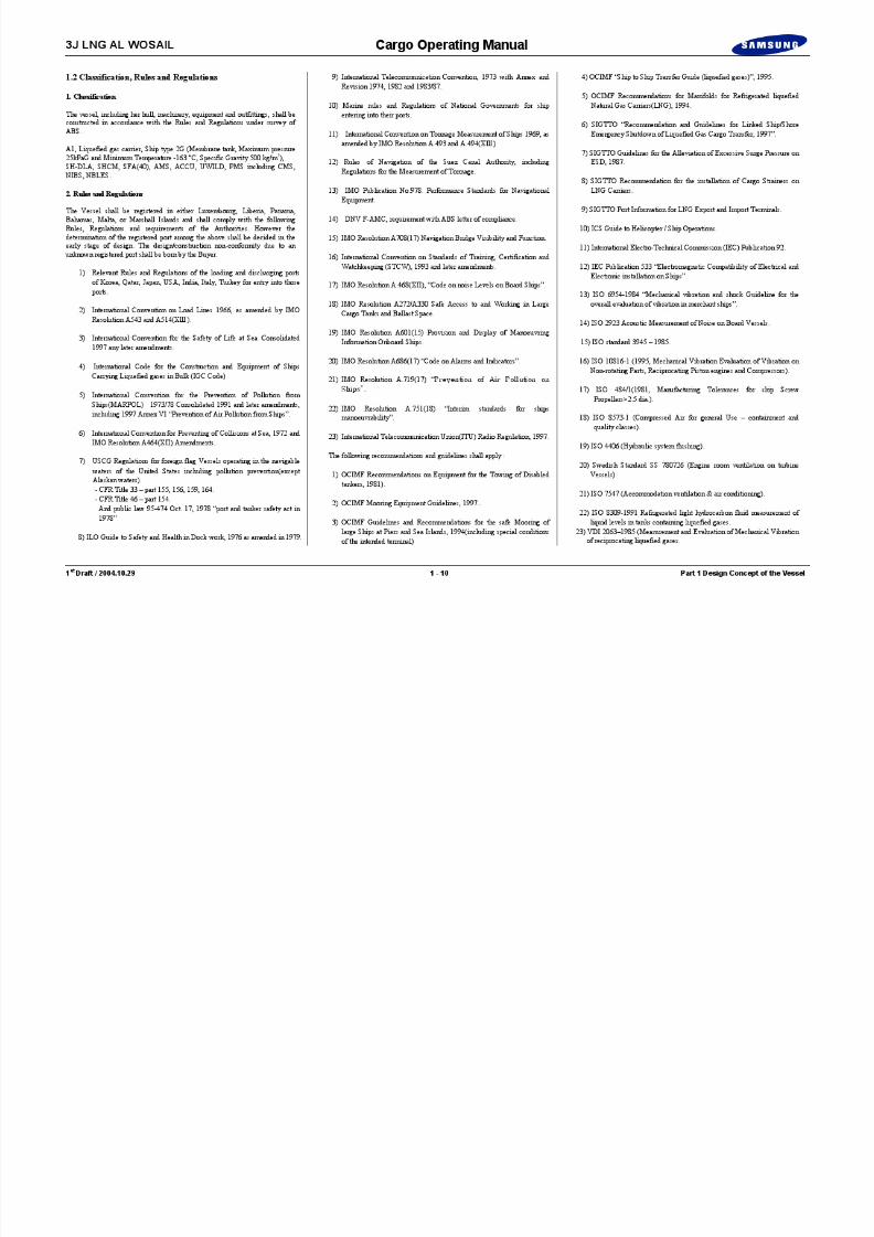
1 st Draft / 2004.10.29 1 - 11 Part 1 Design Concept of the Vessel
24) BS 1807-1981.
25) VDI 2056 Criteria for Assessment of Mechanical Vibration in Machines.
26) IMO Resolution A343(ix) Recommendation on method of measuringnoise levels at listening posts.
27) ILO Convention Concerning Crew Accommodation on Board Ships(No.92&133)
28) IMPA Recommendations for Pilot ladders.
29) Council Directive 96/98/EC on Marine Equipment as amended byCommission
30) Maritime Traffic Safety Law of Japan (Minimum applicable for foreignflag vessels to visit Japanese seaway.
31) IMO Resolution A868(XX) – Guidelines for the control andmanagement of ship ballast water to minimise the transfer ofharmful aquatic organisms and pathogens.
The Builder shall provide the necessary assistance in preparing for andobtaining approval from the government authorities of the loading anddischarging port for calibration of CTS and cargo tank tables.
If the formal certificate(s) are not obtained at the time of the Vessel’s delivery,the Builder shall furnish the Owner with the provisional certificate(s).In such case(s), the Builder shall deliver the formal certificate(s) to the Owneras soon as available after the Vessel’s delivery.
8/12/2019 LNG Cargo Operating Manual
http://slidepdf.com/reader/full/lng-cargo-operating-manual 20/257
3J LNG AL WOSAIL Cargo Operating Manual
1 st Draft / 2004.10.29 1 - 12 Part 1 Design Concept of the Vessel
Blank Page

8/12/2019 LNG Cargo Operating Manual
http://slidepdf.com/reader/full/lng-cargo-operating-manual 21/257
3J LNG AL WOSAIL Cargo Operating Manual
1 st Draft / 2004.10.29 1 - 13 Part 1 Design Concept of the Vessel
Illustration 1.3.1a Cargo Tank Lining Reinforcement
Ballast
Void
Cofferdam
Duct Keel
Inter Barrier Space Panel
Insulation Space Panel
Secondary Membrane
Primary Membrane
Cofferdam
Void Area
Ballast Tank
Duct Keel
Membrane Sheet

8/12/2019 LNG Cargo Operating Manual
http://slidepdf.com/reader/full/lng-cargo-operating-manual 22/257

8/12/2019 LNG Cargo Operating Manual
http://slidepdf.com/reader/full/lng-cargo-operating-manual 23/257

8/12/2019 LNG Cargo Operating Manual
http://slidepdf.com/reader/full/lng-cargo-operating-manual 24/257
3J LNG AL WOSAIL Cargo Operating Manual
1 st Draft / 2004.10.29 1 - 16 Part 1 Design Concept of the Vessel
Ultimate tensile strength : 600 Kg/cm2 parallel to face grain400 Kg/cm2 perpendicular to face grain
Tensile strength perpendicular to the bonding plane : 2 MPa Shearing strength under tension : 3.5 MPa
92 mm plywood
The 92mm plywood shall be made by the bonding of several plywood panels of15mm nominal thickness. This plywood shall be used for the fabrication ofhardwood keys.
5. Adhesive products
Three (3) different kids of adhesive product shall be supplied by manufacturersand approved by GTT.
Epoxy glue. Loading bearing epoxy mastic, Polyurethane glue.
Epoxy glue
Epoxy glue shall be used for assembling the insulating elementsProduct with two components : resin + hardenerVolumetric mass of mixture : 1.3
Load bearing mastic
Loading bearing mastic shall be used for the supporting of insulating panels.Product with two components : resin + hardenerMixing and application with automatic machineVolume mass of mixture : 1.5
Polyurethane glue
Polyurethane glue shall be used for the prefabrication of the insulation panels.Product with two components : resin + hardenerApplication by spraying system or automatic machine
Volume mass of mixture : 1.3

8/12/2019 LNG Cargo Operating Manual
http://slidepdf.com/reader/full/lng-cargo-operating-manual 25/257
3J LNG AL WOSAIL Cargo Operating Manual
1 st Draft / 2004.10.29 1 - 17 Part 1 Design Concept of the Vessel
Illustration 1.3.1b Cargo Tank General
Pipe Duct
Primary Barrier (Chromium Nical Stainless steel : 1.2mm)
Secondary Barrier (Triplex : Aluminium Foil + Glasscloth)
Hull
Primary Insulation (100mm)
Secondary Insulation (170mm)
Ballast Tanks
Side Passage Way
Inner Deck
Liquid Dome
Vapour Dome
Tripod Mast
Main Cargo Pumps
Stripping/Spray Pump
Filling Line
Discharge Line

8/12/2019 LNG Cargo Operating Manual
http://slidepdf.com/reader/full/lng-cargo-operating-manual 26/257
3J LNG AL WOSAIL Cargo Operating Manual
1 st Draft / 2004.10.29 1 - 18 Part 1 Design Concept of the Vessel
Illustration 1.3.2a Construction of Containment System
Angle Piece
Membrane Sheet
Top Bridge Pad
Secondary Barrier Joint
Flat Panel Anchoring Strip
Plugs
Flat Joint
Stud
Inner Hull
Load Bearing Mastic
Corner Panel
Retainer Levelling Weidge
Stud
8/12/2019 LNG Cargo Operating Manual
http://slidepdf.com/reader/full/lng-cargo-operating-manual 27/257
3J LNG AL WOSAIL Cargo Operating Manual
1 st Draft / 2004.10.29 1 - 19 Part 1 Design Concept of the Vessel
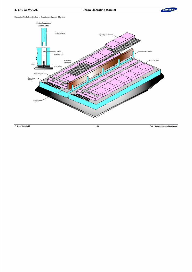
Illustration 1.3.2b Construction of Containment System – Flat Area
Cylindrical plug
Nut HM 10
Washer LL 10
Level wdege
Anchoring strip
Secondarybarrier joint
Top bridge pad
Cylindrical plug
Flat panel
Flat joint
Stud
Fitting Componets
for Flat Panel
Secondarybarrier

8/12/2019 LNG Cargo Operating Manual
http://slidepdf.com/reader/full/lng-cargo-operating-manual 28/257
3J LNG AL WOSAIL Cargo Operating Manual
1 st Draft / 2004.10.29 1 - 20 Part 1 Design Concept of the Vessel
Illustration 1.3.2c Construction of Containment System – Corner Part. 1
F l a t
p a n e
l
Large corrugation profile for B/A B/C D/A D/C
Flat Panel
5
2 5
XS P
X : Resine rope thickness 12.5mm
S: Secondary Insulation 170 mmP : Primary Insulation 10mm
S+P
T r a n s v e r s a
l B u
l k h e a
d
7 5 ± 4 0
340
210 210
± 40
510
525
± 40
340 340 340
1020
340
75 ± 40
30
140880
Longitudinal bulkhead90
S+P+210+210 = 690
40
120
70
55
(X+S+P)/tan(90 ˚/2)+210+210+40 = 742.5
Note :
Actual dimension of inner hull arecompensated by tolerance ± 40
A
A
A
A
ABlack PlywoodTh. 9mm
Insulating foam
Top plywood Th. 9mm
Secondary barrier Glass wool
Back plywood Th. 9mm
Junction band
Insulating foam
Plywood Th. 12mm
Secondary barrier curve joint
A : Bonding with PU GLUE
: Bonding with EPOXY GLUEB
Sandwich Panel
B
B
B

8/12/2019 LNG Cargo Operating Manual
http://slidepdf.com/reader/full/lng-cargo-operating-manual 29/257
3J LNG AL WOSAIL Cargo Operating Manual
1 st Draft / 2004.10.29 1 - 21 Part 1 Design Concept of the Vessel
Illustration 1.3.2.d Construction of Containment System – Corner Part. 2
340
X : Resine rope thickness 12.5mmS: Secondary Insulation 170 mmP : Primary Insulation 10mm
Actual dimension of inner hullare compensated by tolerance
Note :
+40-20
211
151 170
+40-20
45 +40-20
381
2 4 0 . 4
4 8 0 . 8
3 9 6
396
+40-20
340
Flat Panel
5570
321
15 F-J
20
40
70
(S+P)/Tan(135 ˚ /2)+321 = 432.8
(X+S+P)/Tan(135 ˚ /2)+321+15 = 453.1
4 5 + 4 0 - 2 0
F l a t P a n e l
E - G - H - K
S + P
S
X
P
340211
151 170
+40-20
45 +40-20
381
4 8 0 . 8
3 9 6
396
+40-20
340
Flat Panel
40
55
70
70
321
20
15 A-C
(S+P)/Tan(135 ˚ /2)+151+170 = 432.8
(X+S+P)/Tan(135 ˚ /2)+321+15 = 453.1
4 5 + 4 0 - 2 0
E - G - H - K
S + P
S
X
P Corner 3 Corner 3 BIS
Sandwich Panel
Secondary barrier curve joint
Secondary barrier
Top plywoodTh. 9mm
Insulating foam
Back plywoodTh. 9mm
Back plywoodTh. 9mm
Plywood Th. 12mm
Top plywoodTh. 9mm
Junction band
Insulating foam
A : Bonding with PU GLUE
: Bonding with EPOXY GLUEB
A A
A
A
A
A
B
B
B
A
A
A A

8/12/2019 LNG Cargo Operating Manual
http://slidepdf.com/reader/full/lng-cargo-operating-manual 30/257
3J LNG AL WOSAIL Cargo Operating Man al

8/12/2019 LNG Cargo Operating Manual
http://slidepdf.com/reader/full/lng-cargo-operating-manual 31/257
3J LNG AL WOSAIL Cargo Operating Manual
1 st Draft / 2004.10.29 1 - 23 Part 1 Design Concept of the Vessel
The cargo hold will be cleaned and all traces of rust, grease or pollution will beremoved from the inner hull surface before commencing insulation installation.
Fitting of insulation panels to cargo holds shall be done by means of special
handling and securing legs and tools and also special care shall be taken to protect the panels from damage.
Load bearing mastic application and corner panel installation shall be done.Bonding and putting the flat wall panels at their locations shall be done.The panels shall be kept in place with the studs.
5) Inserting of the joint between panelsThe gap between panels shall be filled with glass wool.Form plugs shall be inserted to cover the studs.
6) Bonding of the secondary barrier joints.
The completion of the secondary barrier shall be performed by bonding under pressure and with epoxy adhesive, flat Triplex scabs over the joints between flatwall panels and curved Triplex scabs between corner panels. Hot melt glue shall
be considered based on recommendation by GTT.The tightness of the cover joints shall be checked by visual inspection and localvacuum box test.
7) Installation of the top bridge pads.
Top bridge pads shall be installed between flat panels and also between two (2)adjacent corner panels which are fitted during bonding in the erection work stagein the cargo tanks.
8) Tracing
Tracing and membrane sheet positioning shall be done.
9) Installation of membrane sheets
Installation of the membrane sheets and temporary fixing by clamps shall bedone.
maximum fitting gap permissible shall be 0.3 mm.
10) Tack welding
Tack welding of the edge of membrane sheets onto the anchoring pieces and/oron the overlapped membrane sheet already in place shall be done.
11) Continuous welding operation
Continuous welding operation shall be achieved in order to ensure tightness ofthe primary barrier. This welding operation shall be performed either manually orautomatically.
Simultaneously, angle pieces shall be put in place and welded as for themembrane sheets.

8/12/2019 LNG Cargo Operating Manual
http://slidepdf.com/reader/full/lng-cargo-operating-manual 32/257
3J LNG AL WOSAIL Cargo Operating Manual

8/12/2019 LNG Cargo Operating Manual
http://slidepdf.com/reader/full/lng-cargo-operating-manual 33/257
3J LNG AL WOSAIL Cargo Operating Manual
1 st Draft / 2004.10.29 1 - 25 Part 1 Design Concept of the Vessel
Illustration 1.4a Hazardous Areas and Gas Dangerous Zone Plan

8/12/2019 LNG Cargo Operating Manual
http://slidepdf.com/reader/full/lng-cargo-operating-manual 34/257

8/12/2019 LNG Cargo Operating Manual
http://slidepdf.com/reader/full/lng-cargo-operating-manual 35/257
3J LNG AL WOSAIL Cargo Operating Manual
8/12/2019 LNG Cargo Operating Manual
http://slidepdf.com/reader/full/lng-cargo-operating-manual 36/257
g p g
1 st Draft / 2004.10.29 Part 2 Properties of Gases
Part 2 : Properties of Gases 2.1 Characteristics of LNG............ ............ ............ ............ ............ .......... 2 - 2
2.1.1 Physical Properties and Composition of LNG........ ............ .... 2 - 22.1.2 Flammability of Methane, Oxygen and Nitrogen Mixtures.... 2 - 3
2.1.3 Supplementary Characteristics of LNG ............ ............ .......... 2 - 42.1.4 Avoidance of Cold Shock to Metal ............ ........... ............ ...... 2 - 6
2.2 Properties of Nitrogen and Inert Gas... ............ ............ ............ .......... 2 - 7
Part 2Properties of Gases
3J LNG AL WOSAIL Cargo Operating Manual
8/12/2019 LNG Cargo Operating Manual
http://slidepdf.com/reader/full/lng-cargo-operating-manual 37/257
1 st Draft / 2004.10.29 2 - 1 Part 2 Properties of Gases
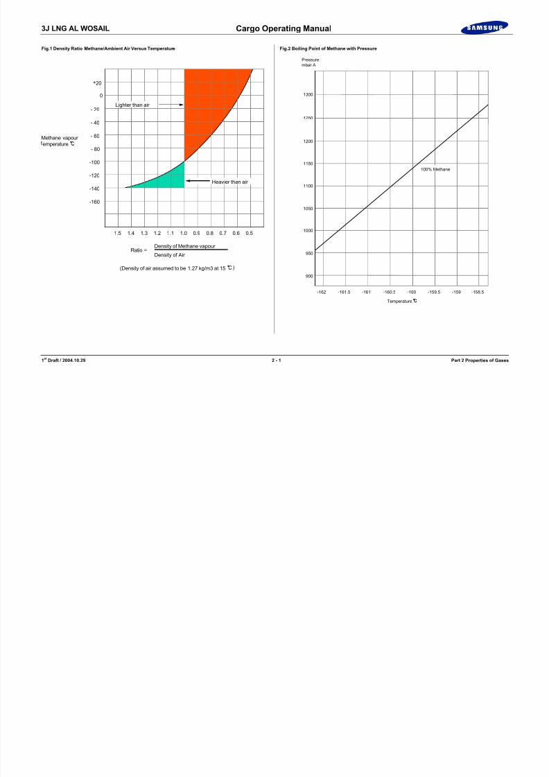
Fig.1 Density Ratio Methane/Ambient Air Versus Temperature
+20
0
- 20
- 40
- 60
1.5 1.4 1.3 1.2 1.1 1.0 0.9 0.8 0.7 0.6 0.5
- 80
-100
-120
-140
-160
Lighter than air
Ratio =Density of Methane vapour
Density of Air
(Density of air assumed to be 1.27 kg/m3 at 15
Methane vapour emperature
Heavier than air
)
Fig.2 Boiling Point of Methane with Pressure
900
950
1000
1050
1100
1150
1200
1250
1300
-162 -161.5 -161 -160.5 -160 -159.5 -159 -158.5
Pressurembar A
Temperature
100% Methane

8/12/2019 LNG Cargo Operating Manual
http://slidepdf.com/reader/full/lng-cargo-operating-manual 38/257

8/12/2019 LNG Cargo Operating Manual
http://slidepdf.com/reader/full/lng-cargo-operating-manual 39/257

8/12/2019 LNG Cargo Operating Manual
http://slidepdf.com/reader/full/lng-cargo-operating-manual 40/257
8/12/2019 LNG Cargo Operating Manual
http://slidepdf.com/reader/full/lng-cargo-operating-manual 41/257

8/12/2019 LNG Cargo Operating Manual
http://slidepdf.com/reader/full/lng-cargo-operating-manual 42/257

8/12/2019 LNG Cargo Operating Manual
http://slidepdf.com/reader/full/lng-cargo-operating-manual 43/257
3J LNG AL WOSAIL Cargo Operating Manual
8/12/2019 LNG Cargo Operating Manual
http://slidepdf.com/reader/full/lng-cargo-operating-manual 44/257
1 st Draft / 2004.10.29 Part 3 Integrated Automation System
Part 3 : Integrated Automation System (IAS) 3.1 General ............................................................................................. 3 - 4
3.2 IAS Overview................................................................................... 3 - 4
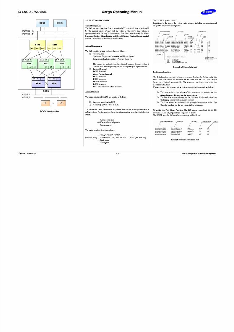
3.3 IAS Function Guide.......................................................................... 3 - 6
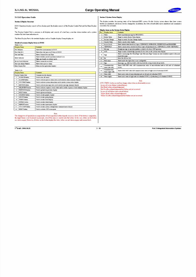
3.4 IAS Operation Guide ...................................................................... 3 - 10
Part 3Integrated Automation System (IAS)
3J LNG AL WOSAIL Cargo Operating Manual

8/12/2019 LNG Cargo Operating Manual
http://slidepdf.com/reader/full/lng-cargo-operating-manual 45/257
1 st Draft / 2004.10.29 3 - 1 Part 3 Integrated Automation System
Illustration 3.1.1a IAS Overview
DOHS
DOHSPER SONNEL
ALARM SYSTEM
ALARMPRINTER
LOGGINGPRINTER
COLOR HARDCOPIER
WHEEL HOUSE
EXTENSION VDUSYSTEM
EXT. VDU NET(ETHERNET)
DOGS
EXT. VDUSERVER
DOGS
EXT. VDUSERVER
DOPC
4 SETS
Cargo Control Console Engine control Console
DOGS
COLOR HARDCOPIER
ALARMPRINTER
LOGGINGPRINTER
DOSS DOSS DOSS DOSSDOSS DOSS DOSS DOSS
DEO-NET (ETHERNET)
RECEPTACLES FORPOTABLE EXTENSION VDU
- 2 IN SR OFF CABIN SPARE
- 4 IN JR OFF CABIN SPARE- 1 IN GENERAL OFFICE- 1 IN CONFERENCE ROOM- 1 IN DOCUMENT ROOM- 1 IN EER- 1 IN No.1 CSB ROOM- 1 IN No.1 MSB ROOM- 1 IN Electrical work shop- 1 IN ENGINE STORE
Electrical/E CABIN
SERIAL COMMUNICATION I/FFOR CARGO SYSTEM- CUSTODY TRANSFER SYSTEM (DUAL)- LOADING COMPUTER (DUAL)- FLOAT TYPE LEVEL GAUGE SYSTEM- INTEGRATED NAVIGATION SYSTEM (INS)- GAS DETECTION SYSTEM
FOR MACHINERY SYSTEM- FIRE DETECTION SYSTEM- SHIP PERFORMANCE MONITORING SYSTEM- VOYAGE DATA RECORDER(VDR)
DOHSEXTENSION
ALARM PANEL
27 PANELS
LEGEND
DOSS : DEO OPEN SUPERVISORY STATIONDOHS : DEO OPEN HISTORY STATIONDOPC : DEO PROCESS CONTROLLERDOGS : DEO OPEN GATEWAY STATION
CCR (Cargo Control Room) ECR (Engine Control Room)
PORTABLEEXTENSION VDU
3 SETS
DOSS DOSS
PlasmaDisplay
DOPC
DOHS
3 SETS
DOPCDOPC
3/E CABIN
2/E CABIN
Cargo/E DAY RM
1/E DAY RM
Ch/E DAY RM
3/O CABIN
2/O CABIN
1/O DAY RM
Captain DAY RMCh/O DAY RM
MACHINERY I/O CABINETCARGO I/O CABINETCARGO I/O CABINET
SERIAL COMMUNICATION I/ FOPC COMMUNICATIONFOR CARGO & MACHINERY SYSTEMSHIPBOARD MANAGEMENT SYSTEM
3J LNG AL WOSAIL Cargo Operating Manual

8/12/2019 LNG Cargo Operating Manual
http://slidepdf.com/reader/full/lng-cargo-operating-manual 46/257
1 st Draft / 2004.10.29 3 - 2 Part 3 Integrated Automation System
Illustration 3.1.1b IAS Overview
DOPC
CCC
DOSS DOSS DOSS DOSS
OPT.CONV.
OPT(2 FIBERS)
OPT(2 FIBERS)
ECC
DOSS DOSS DOSS DOSS
OPT(2 FIBERS)
DOPC DOPC
DOHS
W/H CONSOLE
DOSS DOSS
OPT.CONV.
OPT(2 FIBERS)
OPT(2 FIBERS)
DEO-NET(ETHERNET)
DOGS DOGS
CARGO I/O CABINET
EXT. VDU NET(ETHERNET)
EXTENSION & POTABLE VDUS
DOPC
I/O
DOPC
I/O I/O
DOPC DOPC
I/O I/O
DOHSDOHS
PERSONNEL ALARM SYSTEMDOHS
EXTENSION ALARM PANEL
MACHINERY I/O CABINET
LEGEND
DOSS : DEO OPEN SUPERVISORY STATIONDOHS : DEO OPEN HISTORY STATIONDOPC : DEO PROCESS CONTROLLERDOGS : DEO OPEN GATEWAY STATIONOPT. CONV. : OPTICAL CONVERTORSIM : SE RIAL INTERFACE MODULE
OPT(2 FIBERS)
OPT.CONV.
OPT.CONV.
OPT.CONV.
OPT.CONV.
OPT.CONV.
OPT.CONV.
I/O I/O I/O
I/O I/O I/O I/O I/O
I/O I/O I/O I/O
I/O SIM OPT(2 FIBERS)
OPT(2 FIBERS)
DOGS
To SMS(ETHERNET)
No.2 BLR CONTROL PANEL No.1 BLR CONTROL PANEL

8/12/2019 LNG Cargo Operating Manual
http://slidepdf.com/reader/full/lng-cargo-operating-manual 47/257

8/12/2019 LNG Cargo Operating Manual
http://slidepdf.com/reader/full/lng-cargo-operating-manual 48/257
8/12/2019 LNG Cargo Operating Manual
http://slidepdf.com/reader/full/lng-cargo-operating-manual 49/257
8/12/2019 LNG Cargo Operating Manual
http://slidepdf.com/reader/full/lng-cargo-operating-manual 50/257

8/12/2019 LNG Cargo Operating Manual
http://slidepdf.com/reader/full/lng-cargo-operating-manual 51/257

8/12/2019 LNG Cargo Operating Manual
http://slidepdf.com/reader/full/lng-cargo-operating-manual 52/257

8/12/2019 LNG Cargo Operating Manual
http://slidepdf.com/reader/full/lng-cargo-operating-manual 53/257
8/12/2019 LNG Cargo Operating Manual
http://slidepdf.com/reader/full/lng-cargo-operating-manual 54/257

8/12/2019 LNG Cargo Operating Manual
http://slidepdf.com/reader/full/lng-cargo-operating-manual 55/257

8/12/2019 LNG Cargo Operating Manual
http://slidepdf.com/reader/full/lng-cargo-operating-manual 56/257
8/12/2019 LNG Cargo Operating Manual
http://slidepdf.com/reader/full/lng-cargo-operating-manual 57/257

8/12/2019 LNG Cargo Operating Manual
http://slidepdf.com/reader/full/lng-cargo-operating-manual 58/257

8/12/2019 LNG Cargo Operating Manual
http://slidepdf.com/reader/full/lng-cargo-operating-manual 59/257

8/12/2019 LNG Cargo Operating Manual
http://slidepdf.com/reader/full/lng-cargo-operating-manual 60/257

8/12/2019 LNG Cargo Operating Manual
http://slidepdf.com/reader/full/lng-cargo-operating-manual 61/257

8/12/2019 LNG Cargo Operating Manual
http://slidepdf.com/reader/full/lng-cargo-operating-manual 62/257

8/12/2019 LNG Cargo Operating Manual
http://slidepdf.com/reader/full/lng-cargo-operating-manual 63/257

8/12/2019 LNG Cargo Operating Manual
http://slidepdf.com/reader/full/lng-cargo-operating-manual 64/257

8/12/2019 LNG Cargo Operating Manual
http://slidepdf.com/reader/full/lng-cargo-operating-manual 65/257

8/12/2019 LNG Cargo Operating Manual
http://slidepdf.com/reader/full/lng-cargo-operating-manual 66/257

8/12/2019 LNG Cargo Operating Manual
http://slidepdf.com/reader/full/lng-cargo-operating-manual 67/257
8/12/2019 LNG Cargo Operating Manual
http://slidepdf.com/reader/full/lng-cargo-operating-manual 68/257

8/12/2019 LNG Cargo Operating Manual
http://slidepdf.com/reader/full/lng-cargo-operating-manual 69/257
3J LNG AL WOSAIL Cargo Operating Manual
4.2. 3 Mode Selection
1. Ballast and Laden Mode
Fig. 1 Ballast and Laden Mode Logic
V H d M i P (Ab )

8/12/2019 LNG Cargo Operating Manual
http://slidepdf.com/reader/full/lng-cargo-operating-manual 70/257
1 st Draft / 2004. 10. 29 4 - 8 Part 4 Cargo System
There are two pressure controllers, one for Laden Voyage and one for BallastVoyage, in the GMS that tell the Boiler Management System (BMS) how much
boil-off gas is available to the burner or how much gas has to be released toatmosphere to keep the vapour header pressure at its set point.Manual inputs are the “Estimated BOG Flow” in Laden and Ballast mode and the
pressure selection switch that enables the operator to select between absolute orgauge pressure (for Laden mode).The pressure controllers will protect the cargo tanks and adjust the “AvailableBOG Flow” according to its set point. To control the vapour header pressureeither the ballast or laden pressure controller will be active at all times.The logic is the same for ballast and laden mode but separate controllers are usedfor the two.Switching between Laden and Ballast mode is performed during loading /
unloading.
1) Pressure Sensor Mode
Voyage Mode Pressure Sensor Pressure RangeBallast Gauge Only option.
Absolute When the vapour headerpressure is above 5 kPa.
LadenGauge When the vapour header
pressure is below 5 kPa.Switching between absolute and gauge pressure is bump-less and can bedone at any time.
2) Failsafe Handling Ballast Mode Controller
Cause Effect CommentsVapour header pressuremeasurement signalfailure.
Controller put in manualmode with the currentcontroller output.
Gaugepressure.
3) Failsafe Handling Laden Mode Controller
Cause Effect Comments
Vapour header pressuremeasurement signalFailure.
Controller put in manualmode with the currentcontroller output.
Gaugepressure.
Vapour header pressuremeasurement signalFailure.
Controller put in manualmode with the currentcontroller output.
Absolutepressure.
SetLaden mode press controller
FeedF
Available BOG Flow (kg/h)
Set
Est. BOG FlowBallast Mode (kg/h)
Ballast mode press controller
Ballast Laden
Gauge Abs
Est. BOG FlowLaden Mode (kg/h)
Vapor Header Main Pressure (Abs)
Vapor Header Main Pressure (Gauge)
FeedF
3J LNG AL WOSAIL Cargo Operating Manual
Illustration 4.3.1a Main Cargo Pumps

8/12/2019 LNG Cargo Operating Manual
http://slidepdf.com/reader/full/lng-cargo-operating-manual 71/257
1 st Draft / 2004. 10. 29 4 - 9 Part 4 Cargo System
0 500 1,000 1,500 2,000
100
200
300
400
500
0
20
40
60
80
100
120
140
160
180
200
0
1
2
3
4
Characteristic Curve ofCargo Pump
Capacity Q (m 3 /h)
T o t a l H e a d H ( m )
P u m p
E f f i c i e n c y E ( % )
S h a f t H o r s e P o w e r P ( k W )
N P S H R H s ( m )
P u m p
D o w n H d ( m )
H e i g h t f r o m I n d u c e r I n l e t
H
E
P
Hs Hd
PUMP Motor Capacity : 1,700 m 3 /h Output : 530 kWTotal Head : 155 m Synchronous Speed : 1,800 rpmSuc. Head : – m Electric Source : AC 6,600V 60 HzLiquid Name : LNGTemp erat ure : -16 3 ˚ CSpecific Gravity : 0.5Minimum F low : 650 m 3 /h
TERMINAL BOX
INDUCER
SUCTION TANK BOTTOM
SUCTION STRAINER
IMPELLER
BALL BEARING
SHAFT
CABLE
STATOR CORE
BALANCE SEAT
ROTOR CORE
STATOR COIL
BALL BEARING
2,270 mm
DISCHARGE
810 mm

8/12/2019 LNG Cargo Operating Manual
http://slidepdf.com/reader/full/lng-cargo-operating-manual 72/257

8/12/2019 LNG Cargo Operating Manual
http://slidepdf.com/reader/full/lng-cargo-operating-manual 73/257

8/12/2019 LNG Cargo Operating Manual
http://slidepdf.com/reader/full/lng-cargo-operating-manual 74/257
3J LNG AL WOSAIL Cargo Operating Manual
Illustration 4.3.2a Stripping/Spray Pumps
DISCHARGE

8/12/2019 LNG Cargo Operating Manual
http://slidepdf.com/reader/full/lng-cargo-operating-manual 75/257
1 st Draft / 2004. 10. 29 4 - 13 Part 4 Cargo System
PUMP Motor Capacity : 50 m 3 /h Output: 24 kWTotal Head : 145 m Synchronous Speed :3,600 rpmSuc. Head : – m Electric Source: AC 440V 60 HzLiquid Name : LNGTemp erat ure : -163 ˚ CSpecific Gravity : 0.5Minimum F low : 20 m 3 /h
0
5
10
15
0
20
40
60
120
140
160
0
0.5
1.0
1.5
Characteristic Curve ofStripping/Spray Pump
Capacity Q (m 3 /h)
T o t a l H e a d H ( m )
P u m p
E f f i c i e n c y E ( % )
S h a f t H o r s e P o w e r P
( k W )
N P S H R H s ( m )
P u m p
D o w n
H d ( m )
H e i g h t f r o m I n d u c e r I n l e t
H
E
P
HsHd
180
10 20 30 40 50 60
202.0
80
SUCTIONTANK BOTTOM
DISCHARGE
1,460 mm
TERMINAL BOX
INDUCER
SUCTION STRAINER
IMPELLER
BALL BEARING
SHAFT
CABLE
ROTOR CORE
BALANCE SEAT
STATOR CORE
STATOR COIL
BALL BEARING

8/12/2019 LNG Cargo Operating Manual
http://slidepdf.com/reader/full/lng-cargo-operating-manual 76/257
8/12/2019 LNG Cargo Operating Manual
http://slidepdf.com/reader/full/lng-cargo-operating-manual 77/257
3J LNG AL WOSAIL Cargo Operating Manual

8/12/2019 LNG Cargo Operating Manual
http://slidepdf.com/reader/full/lng-cargo-operating-manual 78/257
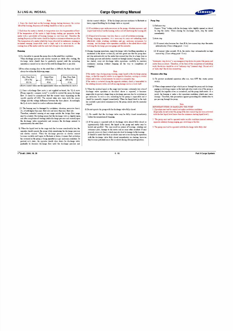
1 st Draft / 2004. 10. 29 4 - 16 Part 4 Cargo System
Blank Page
3J LNG AL WOSAIL Cargo Operating Manual
Illustration 4.3.3a Emergency Cargo Pump
Characteristic Curve of
TERMINAL HEADER

8/12/2019 LNG Cargo Operating Manual
http://slidepdf.com/reader/full/lng-cargo-operating-manual 79/257
1 st Draft / 2004. 10. 29 4 - 17 Part 4 Cargo System
0
0
50
100
150
0
20
40
60
120
140
160
180
0
1.0
2.0
3.0
Characteristic Curve of
Emergency Cargo Pump
Capacity Q (m 3 /h)
T o t a l H e a l H ( m )
P u m p
E f f i c i e n c y E ( % )
S h a f t H o r s e P o w e r P ( k W )
N P S H R H s ( m )
P u m p
D o w n H d ( m )
H e i g h t f r o m I n d u c e r I n l e t
H
E
P
Hs Hd
PUMP Motor Capacity : 550 m 3 /h Output: 200 kWTotal Head : 155 m Synchronous Speed : 3,600 rpmSuc. Head : – m Electric Source: AC 440V 60 HzLiquid Name : LNGTemp er at ur e : -16 3 ˚ CSpecific Gravi ty : 0 .5Minimum Flow : 220 m 3 /h
80
200
100 200 300 400 500 600 700
4.0
5.0 200
TANK BOTTOM
EMERG. C.PUMP
WORKING LEVELLIQUID DOME TOP
POWER CABLE
COLUME COVER
FLEXIBLE CABLE
JUNCTION BOXN2 GASINLET
TO SWITCHBOARD
SUPPORT WIRE ROPE
GUIDE ROLLER
POWER CABLE
FOOT VALVESUCTION
DISCHARGE
1,900 mm
520 mm

8/12/2019 LNG Cargo Operating Manual
http://slidepdf.com/reader/full/lng-cargo-operating-manual 80/257

8/12/2019 LNG Cargo Operating Manual
http://slidepdf.com/reader/full/lng-cargo-operating-manual 81/257
3J LNG AL WOSAIL Cargo Operating Manual

8/12/2019 LNG Cargo Operating Manual
http://slidepdf.com/reader/full/lng-cargo-operating-manual 82/257
1 st Draft / 2004. 10. 29 4 - 20 Part 4 Cargo System
Blank Page
3J LNG AL WOSAIL Cargo Operating Manual
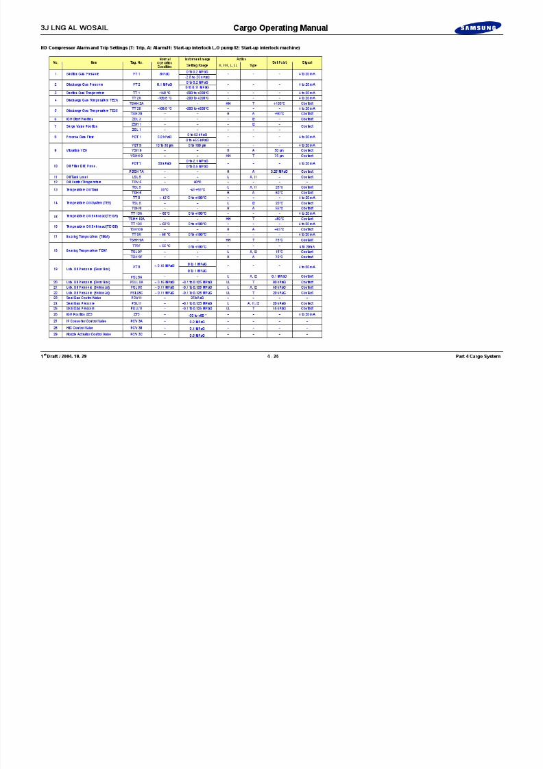
Illustration 4.4.1a HD Compressor
VENT
PLLL
PAL11
PI1A
PI2A
TAHH2A
TI2B
TAH2B
T PLLL
TLHHTT
PLLLT
TLHHT A
I2 I1
A A A
L15 5
PI8
PAL8
TAL8
TAH8
TI8
PALL8A
I2
TAL9F
TAHH
9APALL
8C
TLHHT
T
TAHH10A
TI10B
PAL8C
TAH9F
TI9F
TAH10B
A A
COMMONTRIP
T
PALL11
CUSTOMER
CRYOSTAR

8/12/2019 LNG Cargo Operating Manual
http://slidepdf.com/reader/full/lng-cargo-operating-manual 83/257
1 st Draft / 2004. 10. 29 4 - 21 Part 4 Cargo System
PSLL
PCV11
11PSL11
PI
3AZI
1PDI
1FIC
F
PCV
PCV3A
3B
PI
PI
11
I/P3HY
TSH
TSL
ZSHIC3 3
3
P
ZE
HS3 L/R
DAC3
3
ZSL3
ZI
1FE
LG
H5TCV
5
5A
5
5 TI
5
1
5LSL
DV
FY
ZSL
1
I/P
S
T
D5
PT8
8BPI
77B7APSV
DV5
F5A
F5B
HSH6
5CF
6AOP
1 . 5
6APSV6B
6CV
PSV6B
8 bar Set :
6BV
6A
HSL6
EMLH
6BCV
6A
1.5
V
C
PCV
SEALBULKHEAD
DRTD
B
58
BULKHEAD
C
CV
TE8
8APSLL
TE9A
TE9F
PSLPSLL8C 8C
PDI
TI8
F7
PDI PDT7A
PDT
PT2
TETE2A 2B2
PI1
TI2
LOCKEDOPEN
LOCKEDOPEN
AUX.L.O.
PUMP
COMPRESSOR ROOM
MOTOR ROOM
FILL
F3
PDI1A/1B
EM6
6
OP6B
DV6
EMY6
TI6A
PI6A
PI6B
TI6B
C6
TCV6
V6F
PT1
A
A
S TE AM IN LE T S TE AM OU TL ETREMOTE CONTROL SIGNALREMOTE
STARTREMOTE
STOP
AUX.L.O. PUMPRUNNING
READY TOSTART AUX.
L.O. PUMP
AUX. L.O. PUMPOVERLOAD
WATERIN
WATEROUT
OIL FILTER
OILCOOLER
POWER ONEMERGENCYSTOP
EMERGENCYSTOP
READY TOSTART
COMPRESSOR
READY TOSTART
AUX. L.O. PUMP
EMERGENCYSTOP
EXTERNALSHUTDOWN
LOCAL/REMOTECOMPRESSORRUNNING
GEAR BOX
E-MOTOR
OIL PUMPRUNNING
STARTL.O. PUMP
STOPL.O. PUMP
4-20mA
INSTRUMENT AIR
SEAL GAS
SURGE CONTROL
PROCESS GAS IN
PROCESS GAS OUT
COMPRESSOR
IGVMAIN
OIL PUMP
PCV3C
V3C
FI11
F11
PI11
11T 8A
T A
A A
9ATT 8CT2A T A A A
A A
A
A A
PT1A
PDT1
ZSH1
ZT3
PT2A
TSHH2A
TT2A
TSH2B
TT2B
PSL8A
PT8A
TT8
TSH8
TT9A
TSHH9A
TT9F TT
10ATT
10B
TE10A
TE10B
TSHH10A
TSH10B
L15.6
L15.4
L15.3
L15.2
CONTROLSYSTEM
ABNORMAL
L15.9
CONTROLMOTOR
ABNORMAL
L15.8
AUX. L.O. PUMPMOTOR FAIL
L
HS15.1
STARTCOMPRESSOR
HSH15.2
HORN
CA15
L15.1
COMMON ALARM
15.5
EMS15
EMS15
POWER ON
L15.1
TSL9F
TSH9F
TSL8
AI2 10AT
REMOTE STARTCOMPRESSOR
STOPCOMPRESSOR
HSL15.2
REMOTE STOPCOMPRESSOR
COMPRESSORMOTOR ABNORMAL
READY TO START AUX. L.O. PUMP
CRYOSTAR
CUSTOMER
LAMPTEST
HS15.4
HORNSILENCE
HS15.5
RESET
HS15.3
PDI7A
PDAH7A
PDSH7A
COMPRESSORRUNNING
CONTROL SYSTEMTROUBLE
REMOTE
READY TO STARTMOTOR
READY TO STARTCOMPRESSOR
YI9
YLHH9
YAHH
9
YI
9
YAH
9
TAL
5
TAH
5
LAL
5
ZLL
3
ZL
3
ZLL
1CLOSED
ZLH
1
ZI
3
TI
1OPEN
YT9
YSHH9
YSH9
YE9
YET9
OIL TANK
I1I2I2 I1
A
TT1
TE1
TI1
PDI1
B
F E E D B A C K
LNG Vapour Line
Steam Line
KeyLegend
Fresh Water Line
Instrument Air Line
LO Line
TCargo Control Room
Local Instrument
Local Panel Instrument
Remote Panel Instrument
Trip Circuit
Alarm Circuit
Start-up Interlock L.O Pump
Start-up Interlock Machine
A
I2
I1

8/12/2019 LNG Cargo Operating Manual
http://slidepdf.com/reader/full/lng-cargo-operating-manual 84/257

8/12/2019 LNG Cargo Operating Manual
http://slidepdf.com/reader/full/lng-cargo-operating-manual 85/257

8/12/2019 LNG Cargo Operating Manual
http://slidepdf.com/reader/full/lng-cargo-operating-manual 86/257
8/12/2019 LNG Cargo Operating Manual
http://slidepdf.com/reader/full/lng-cargo-operating-manual 87/257
3J LNG AL WOSAIL Cargo Operating Manual

8/12/2019 LNG Cargo Operating Manual
http://slidepdf.com/reader/full/lng-cargo-operating-manual 88/257
1 st Draft / 2004. 10. 29 4 - 26 Part 4 Cargo System
Blank Page
3J LNG AL WOSAIL Cargo Operating Manual
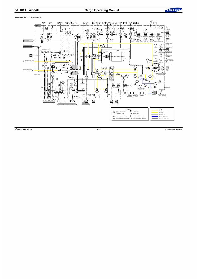
Illustration 4.4.2a LD Compressor
VENT
PLLL11
PAL11
PI1A
PI2A
TAHH2A
TI2B
TAH2B
T PLLL
8ATLHH
9ATT PLLL
8CTTLHH
2A T A
I2 I1
A A
A
A
A
PSL COMMON ALARM
L15.5
L
PI8
PAL8
TAL8
TAH8
TI8
PALL8A
AI2
I2
TAL9F
TAHH
9APALL
8C
TLHH10AT
T
TAHH10A
TI10B
PAL8C
TAH9F
TI9F
TAH10B
A A
COMMONTRIP
T
READY TO STARTMOTOR
PALL11
CUSTOMER
CRYOSTAR
8/12/2019 LNG Cargo Operating Manual
http://slidepdf.com/reader/full/lng-cargo-operating-manual 89/257
1 st Draft / 2004. 10. 29 4 - 27 Part 4 Cargo System
PSLL
PCV11
11PSL11
PI
3AZI
1PDI
1FIC
F
PCV
PCV3A
3B
PI
PI
11
I/P3HY
TSH
TSL
ZSHIC3 3
3
P
ZE
HS3 L/R
DAC3
3
ZSL3
ZI
1FE
LG
H5TCV
5
5A
5
5 TI
5
1
5LSL
DV
FY
ZSL
1
I/P
S
T
D5
PT8
8BPI
77B7APSV
DV5
F5A
F5B
HSH6
5CF
6AOP
1 . 5
6APSV6B
6C
V
PSV6B
8 bar Set :
6BV
6A
HSL6
EMLH
6BCV
6A
1.5
V
C
PCV
SEALBULKHEAD
DRTD
B
58
BULKHEAD
C
CV
TE8
8APSLL
TE9A
TE9F
PSLPSLL8C 8C
PDI
TI8
F7
PDI PDT7A
PDT
PT2
TETE2A 2B2
PI1
TI2
LOCKEDOPEN
LOCKEDOPEN
AUX.L.O.
PUMP
COMPRESSOR ROOM
MOTOR ROOM
FILL
F3
PDI1A/1B
EM6
6
OP6B
DV6
EMY6
TI6A
PI6A
PI6B
TI6B
C6
TCV6
V6F
PT1
A
A
S TE AM IN LE T S TE AM OU TL ETREMOTE CONTROL SIGNALREMOTE
STARTREMOTE
STOP
AUX.L.O. PUMPRUNNING
READY TOSTART AUX.
L.O. PUMP
AUX. L.O. PUMPOVERLOAD
WATERIN
WATEROUT
OIL FILTER
OILCOOLER
POWER ONEMERGENCYSTOP
EMERGENCYSTOP
READY TOSTART
COMPRESSOR
READY TOSTART
AUX. L.O. PUMP
EMERGENCYSTOP
EXTERNALSHUTDOWN
LOCAL/REMOTECOMPRESSORRUNNING
GEAR BOX
E-MOTOR
OIL PUMPRUNNING
STARTL.O. PUMP
STOPL.O. PUMP
4-20mA
INSTRUMENT AIR
SEAL GAS
SURGE CONTROL
PROCESS GAS IN
PROCESS GAS OUT
COMPRESSOR
IGVMAIN
OIL PUMP
PCV3C
V3C
FI11
F11
PI11
T A
A A
A A
A
A A
PT1A
PDT1
ZSH1
ZT3
PT2A
TSHH2A
TT2A
TSH2B
TT2B
PSL8A
PT8A
TT8
TSH8
TT9A
TSHH9A
TT9F TT
10ATT
10B
TE10A
TE10B
TSHH10A
TSH10B
L15.6
L15.4
L15.3
L15.2
CONTROLSYSTEM
ABNORMAL
L15.9
CONTROLMOTOR
ABNORMAL
L15.8
AUX. L.O. PUMPMOTOR FAIL
L
HS15.1
STARTCOMPRESSOR
HSH15.2
HORN
CA15
L15.1
EMS15
EMS15
POWER ON
15.1
TSL9F
TSH9F
TSL8
REMOTE STARTCOMPRESSOR
STOPCOMPRESSOR
HSL15.2
REMOTE STOPCOMPRESSOR
COMPRESSORMOTOR ABNORMAL
READY TO START AUX. L.O. PUMP
CRYOSTAR
CUSTOMER
LAMPTEST
HS15.4
HORNSILENCE
HS15.5
RESET
HS15.3
PDI7A
PDAH7A
PDSH7A
COMPRESSORRUNNING
CONTROL SYSTEMTROUBLE
REMOTE
READY TO STARTCOMPRESSOR
YI9
YLHH9
YAHH9
YI9
YAH9
TAL5
TAH5
LAL5
ZLL3
ZL3
ZLL1
CLOSED
ZLH1
ZI3
TI1
OPEN
YT9
YSHH9
YSH9
YE9
YET9
OIL TANK
I1I2I2 I1
A
TT1
TE1
TI1
PDI1
B
F E E D B A C K
LNG Vapour Line
Steam Line
KeyLegend
Fresh Water Line
Instrument Air Line
LO Line
TCargo Control Room
Local Instrument
Local Panel Instrument
Remote Panel Instrument
Trip Circuit
Alarm Circuit
Start-up Interlock L.O Pump
Start-up Interlock Machine
A
I2
I1

8/12/2019 LNG Cargo Operating Manual
http://slidepdf.com/reader/full/lng-cargo-operating-manual 90/257

8/12/2019 LNG Cargo Operating Manual
http://slidepdf.com/reader/full/lng-cargo-operating-manual 91/257

8/12/2019 LNG Cargo Operating Manual
http://slidepdf.com/reader/full/lng-cargo-operating-manual 92/257

8/12/2019 LNG Cargo Operating Manual
http://slidepdf.com/reader/full/lng-cargo-operating-manual 93/257
3J LNG AL WOSAIL Cargo Operating Manual

8/12/2019 LNG Cargo Operating Manual
http://slidepdf.com/reader/full/lng-cargo-operating-manual 94/257
1 st Draft / 2004. 10. 29 4 - 32 Part 4 Cargo System
Blank Page
3J LNG AL WOSAIL Cargo Operating Manual
Illustration 4.5a Boil off/Warm-up Heater
PT
PT1
PI1

8/12/2019 LNG Cargo Operating Manual
http://slidepdf.com/reader/full/lng-cargo-operating-manual 95/257
1 st Draft / 2004. 10. 29 4 - 33 Part 4 Cargo System
TE1
PT3
PT1
PI1
GAS INLET
TCV2
S
PI3
HIC1 PCV
6
HS1
ZS1
FC
S
STEAM INLET
INSTRUMENTAIR SUPPLY
GAS OUTLETTO DEMISTER
L/R
VENT
DRAIN
CONDENSATE OUT
F C
LNG VAPOUR LINE
STEAM LINE
KEY
CONDENSATE LINE
INSTRUMENT AIR LINE
SV2
PCV2
SV1
ZT1
ZI1
ZT2
ZI2
TCV1 HY
1
PCV1
LI4
LSHH4
LSH4
PI6
HIC2
HS2
ZS2
L/R
TE2
TSHH2
CG917CG918
CG921CG922
CS919CG920
CG923CG924
HY2
ST561FST563F
ST562FST564F
SD551FSD556F
SD552FSD557F
S D 7 0 1 F
S D 7 0 2 F
SD553FSD558F
SD554FSD559F
DRTD
DRTD
DRTD
DRTD
TSLL4
TE4

8/12/2019 LNG Cargo Operating Manual
http://slidepdf.com/reader/full/lng-cargo-operating-manual 96/257
3J LNG AL WOSAIL Cargo Operating Manual
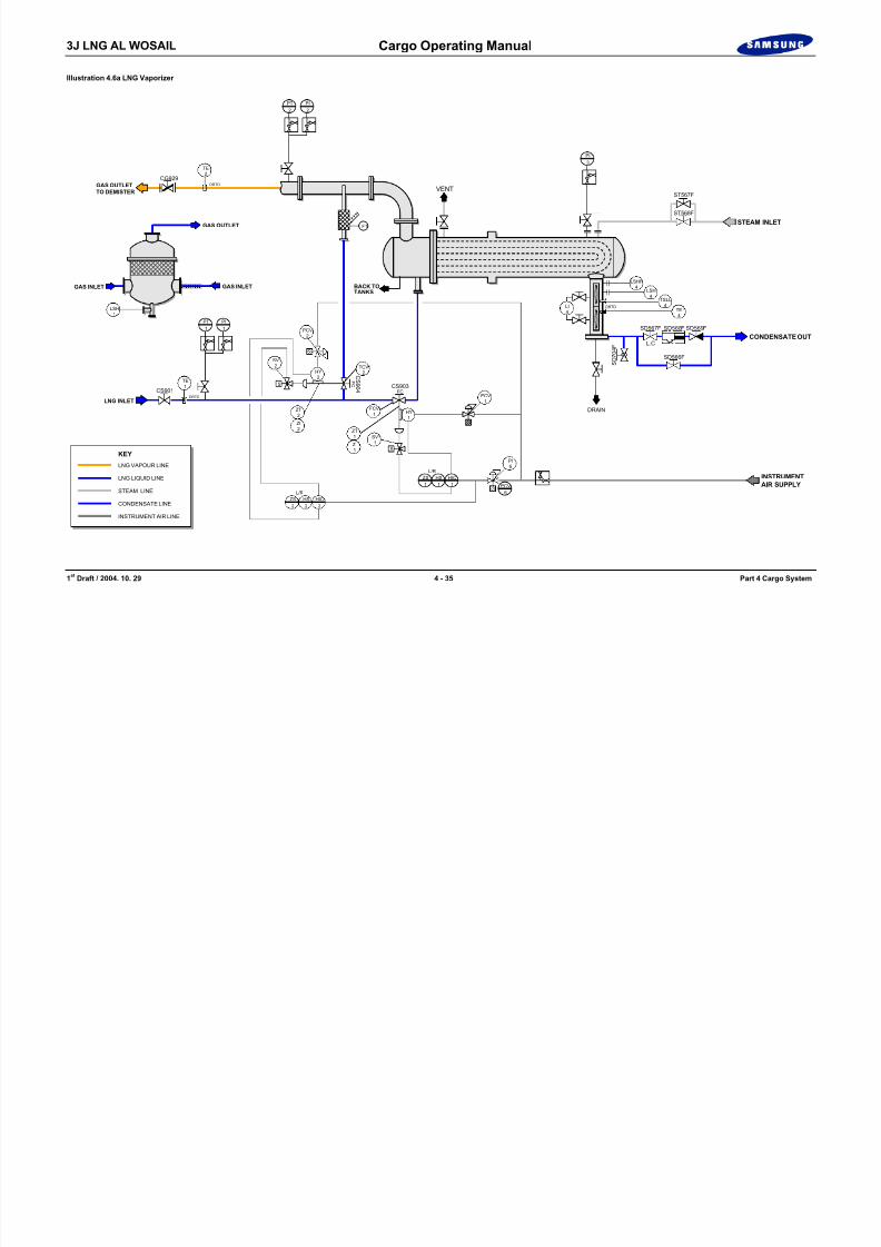
Illustration 4.6a LNG Vaporizer
PT2
PI2
8/12/2019 LNG Cargo Operating Manual
http://slidepdf.com/reader/full/lng-cargo-operating-manual 97/257
1 st Draft / 2004. 10. 29 4 - 35 Part 4 Cargo System
PT1
PI1
LNG INLET
TCV2
S
PI3
HIC1 PCV
6
HS1
ZS1
FC
S
INSTRUMENTAIR SUPPLY
F1
GAS OUTLETTO DEMISTER
L/R
VENT
DRAIN
F C
LNG VAPOUR LINE
STEAM LINE
KEY
CONDENSATE LINE
INSTRUMENT AIR LINE
LNG LIQUID LINE
GAS INLETGAS INLET
LSH1
SV2
PCV2
SV1
ZT1
ZI1
FCV1 HY
1
PCV1
LI4
LSHH4
LSH4
GAS OUTLET
PI6
HIC2
HS2
ZS2
L/R
TE2
CS901
C S 9 0 4
CS903
CG929
TE1
HY2
ZT2
ZI2
STEAM INLET
CONDENSATE OUT
ST567F
ST568F
SD566F
SD567F
L.C
S D 7 0 4 F
SD568F SD569F
BACK TOTANKS
DRTD
DRTD
DRTD
TSLL4
TE4

8/12/2019 LNG Cargo Operating Manual
http://slidepdf.com/reader/full/lng-cargo-operating-manual 98/257
3J LNG AL WOSAIL Cargo Operating Manual
Illustration 4.7a Forcing Vaporizer
PT2
PI2

8/12/2019 LNG Cargo Operating Manual
http://slidepdf.com/reader/full/lng-cargo-operating-manual 99/257
1 st Draft / 2004. 10. 29 4 - 37 Part 4 Cargo System
PT1
PI1
LNG INLET
TCV2
S
PI3
HIC1 PCV
6
HS1
ZS1
FC
S
INSTRUMENTAIR SUPPLY
F1
GAS OUTLETTO DEMISTER
L/R
VENT
DRAIN
F C
LNG VAPOUR LINE
STEAM LINE
KEY
CONDENSATE LINE
INSTRUMENT AIR LINE
LNG LIQUID LINE
GAS INLETGAS INLET
LSH1
SV2
PCV2
SV1
ZT1
ZI1
FCV1 HY
1
PCV1
LI4
LSHH4
LSH4
GAS OUTLET
PI6
HIC2
HS2
ZS2
L/R
TE2
TE1
HY2
ZT2
ZI2
STEAM INLET
CONDENSATE OUTL.C
BACK TOTANKS
DRTD
DRTD
DRTD
TSLL4
TE4
CS902
C S 9 0 6
CS905
CG928
ST565F
ST566F
SD561F
SD562F
S D 7 0 3 F
SD563F SD564F

8/12/2019 LNG Cargo Operating Manual
http://slidepdf.com/reader/full/lng-cargo-operating-manual 100/257
3J LNG AL WOSAIL Cargo Operating Manual
Illustration 4.8.1a Custody Transfer System
Local Displayw/Baragraph
Cargo ControlRoom
CabinetPS4685
1935x600x500HxWxD
GLK-100 Units

8/12/2019 LNG Cargo Operating Manual
http://slidepdf.com/reader/full/lng-cargo-operating-manual 101/257
1 st Draft / 2004. 10. 29 4 - 39 Part 4 Cargo System
Graphic DisplayNL-300
Printer
PointingDevice
g pNL-196
230 VAC
230 VAC
230 VAC
Cargo Computer
Printer
230 VAC
230 VAC
230 VAC
Safe Area
Hazardous Area
CabinetCK-292
760x600x350HxWxd
NL-190 Backup DisplayEA-Computer Power SuppliesZenerbarriersand Terminal boards
ATM Press.Transducer
GT302 UPS Power Unit
24 VDC230 VAC
110/230 VACSupply
1 pair 0.5mm2w/screen
2 pair 0.5mm2w/screen1 pair 1.5 mm2
2 pair twisted 0.5 mm2 w/screen
1 pair 1.5 mm2w/screen
Conn. Box
Pur Cable
PressureTransmitters
GT303Draft
Cargo Tanks
TemperatureSensorsMN3927
Vapour Pressure
Transmitter GT302
StandPipeSections
Radar GLA-100/5
Temp.Box
5 pair twisted 0.5 mm2 w/screen
5 pair twisted 0.5 mm2 w/screen
3 x 0.5 mm2
2 x 10 mm2
3 x 3 x 1.5 mm2
2 x 3 x 2.5 mm2

8/12/2019 LNG Cargo Operating Manual
http://slidepdf.com/reader/full/lng-cargo-operating-manual 102/257

8/12/2019 LNG Cargo Operating Manual
http://slidepdf.com/reader/full/lng-cargo-operating-manual 103/257
3J LNG AL WOSAIL Cargo Operating Manual
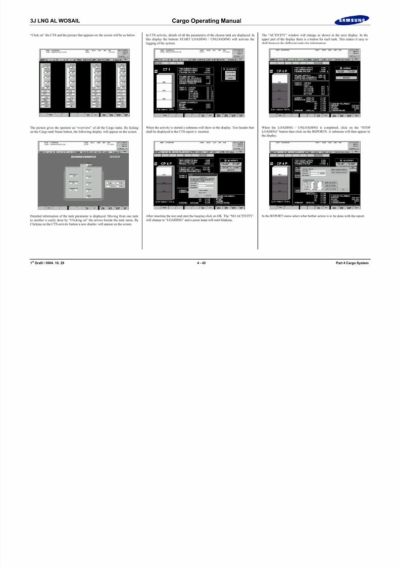
“Click on” the CTS and the picture that appears on the screen will be as below. In CTS activity, details of all the parameters of the chosen tank are displayed. Inthis display the buttons START LOADING / UNLOADING will activate thelogging of the system.
The “ACTIVITY” window will change as shown in the next display. In theupper part of the display there is a button for each tank. This makes it easy toshift between the different tanks for information.
8/12/2019 LNG Cargo Operating Manual
http://slidepdf.com/reader/full/lng-cargo-operating-manual 104/257
1 st Draft / 2004. 10. 29 4 - 42 Part 4 Cargo System
The picture gives the operator an “overview” of all the Cargo tanks. By lickingon the Cargo tank Name button, the following display will appear on the screen:
Detailed information of the tank parameter is displayed. Moving from one tankto another is easily done by “Clicking on” the arrows beside the tank name. ByClicking on the CTS activity button a new display will appear on the screen.
When the activity is started a submenu will show in the display. Text header thatshall be displayed in the CTS report is inserted.
After inserting the text and start the logging click on OK. The “NO ACTIVITY”will change to “LOADING” and a green lamp will start blinking.
When the LOADING / UNLOADING is completed, click on the “STOPLOADING” button then click on the REPORTS. A submenu will then appear inthe display.
In the REPORT menu select what further action is to be done with the report.
3J LNG AL WOSAIL Cargo Operating Manual
To get back to the MAIN MENU click on the button “MAIN MENU”. Click the button “SETUP CONFIG” to enter this display the user will be asked for a password. After inserting the password the following menu will appear on thescreen.
After selecting “SET IN AUTOMATIC” or “SET NEW VALUES” the systemreturns back to the menu display. A new selection of functions can then be made.If the operator selects “TEMP SENSOR CTS” the following display will comeon the screen.
Selecting the “CARGO TANKS” the display below will come on the screen.Changing of ALARM limits in the system can be done in t his display.

8/12/2019 LNG Cargo Operating Manual
http://slidepdf.com/reader/full/lng-cargo-operating-manual 105/257
1 st Draft / 2004. 10. 29 4 - 43 Part 4 Cargo System
In this menu different system parameters can be selected and changed. Thesystem also allows the user to enter manual values for some parameters that will
be used instead of automatically read values. If TRIM / LIST is selected thefollowing picture will appear.
Manually values for TRIM / LIST can be inserted and used in the system.
Normally two sets of temperature sensors are installed in the tank, one set asspare. In this picture the operator can select what sensors that shall be used in theCTS calculation on the different tank. Clicking on “PREV MENU” will return to“CONFIG MENU”. If “TEMP SENSORS MAN.SET” is selected the followingdisplay will show. In this display manually entered values can be inserted andused in the system.
Click on the “CARGO TANK DETAILS” in the config set up menu and thefollowing display will show. This picture gives information on radar parametersetting.
3J LNG AL WOSAIL Cargo Operating Manual
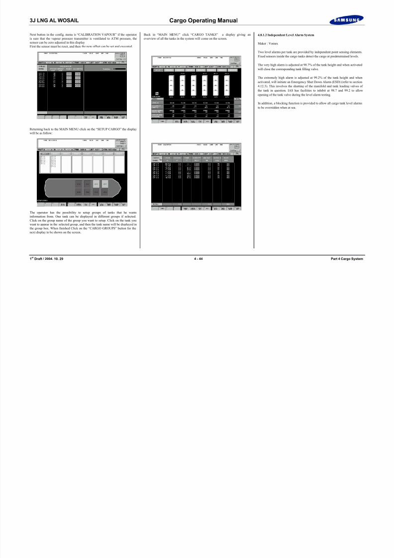
Next button in the config. menu is “CALIBRATION VAPOUR” if the operatoris sure that the vapour pressure transmitter is ventilated to ATM pressure, thesensor can be zero adjusted in this display.First the sensor must be reset, and then the new offset can be set and executed.
Back in “MAIN MENU” click “CARGO TANKS” a display giving anoverview of all the tanks in the system will come on the screen.
4.8.1.2 Independent Level Alarm System
Maker : Vomex
Two level alarms per tank are provided by independent point sensing elements.Fixed sensors inside the cargo tanks detect the cargo at predetermined levels.
The very high alarm is adjusted at 98.7% of the tank height and when activatedwill close the corresponding tank filling valve.
8/12/2019 LNG Cargo Operating Manual
http://slidepdf.com/reader/full/lng-cargo-operating-manual 106/257
1 st Draft / 2004. 10. 29 4 - 44 Part 4 Cargo System
Returning back to the MAIN MENU click on the “SETUP CARGO” the displaywill be as follow:
The operator has the possibility to setup groups of tanks that he wantsinformation from. One tank can be displayed in different groups if selected.Click on the group name of the group you want to setup. Click on the tank youwant to appear in the selected group, and then the tank name will be displayed inthe group box. When finished Click on the “CARGO GROUPS” button for thenext display to be shown on the screen.
The extremely high alarm is adjusted at 99.2% of the tank height and whenactivated, will initiate an Emergency Shut Down Alarm (ESD) (refer to section4.12.3). This involves the shutting of the manifold and tank loading valves ofthe tank in question. IAS has facilities to inhibit at 98.7 and 99.2 to allowopening of the tank valve during the level alarm testing.
In addition, a blocking function is provided to allow all cargo tank level alarmsto be overridden when at sea.
3J LNG AL WOSAIL Cargo Operating Manual
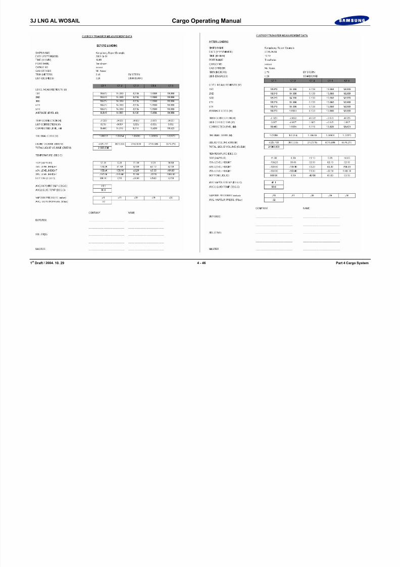
Computer Cargo Record Sheets

8/12/2019 LNG Cargo Operating Manual
http://slidepdf.com/reader/full/lng-cargo-operating-manual 107/257
1 st Draft / 2004. 10. 29 4 - 45 Part 4 Cargo System
3J LNG AL WOSAIL Cargo Operating Manual
8/12/2019 LNG Cargo Operating Manual
http://slidepdf.com/reader/full/lng-cargo-operating-manual 108/257
1 st Draft / 2004. 10. 29 4 - 46 Part 4 Cargo System
3J LNG AL WOSAIL Cargo Operating Manual
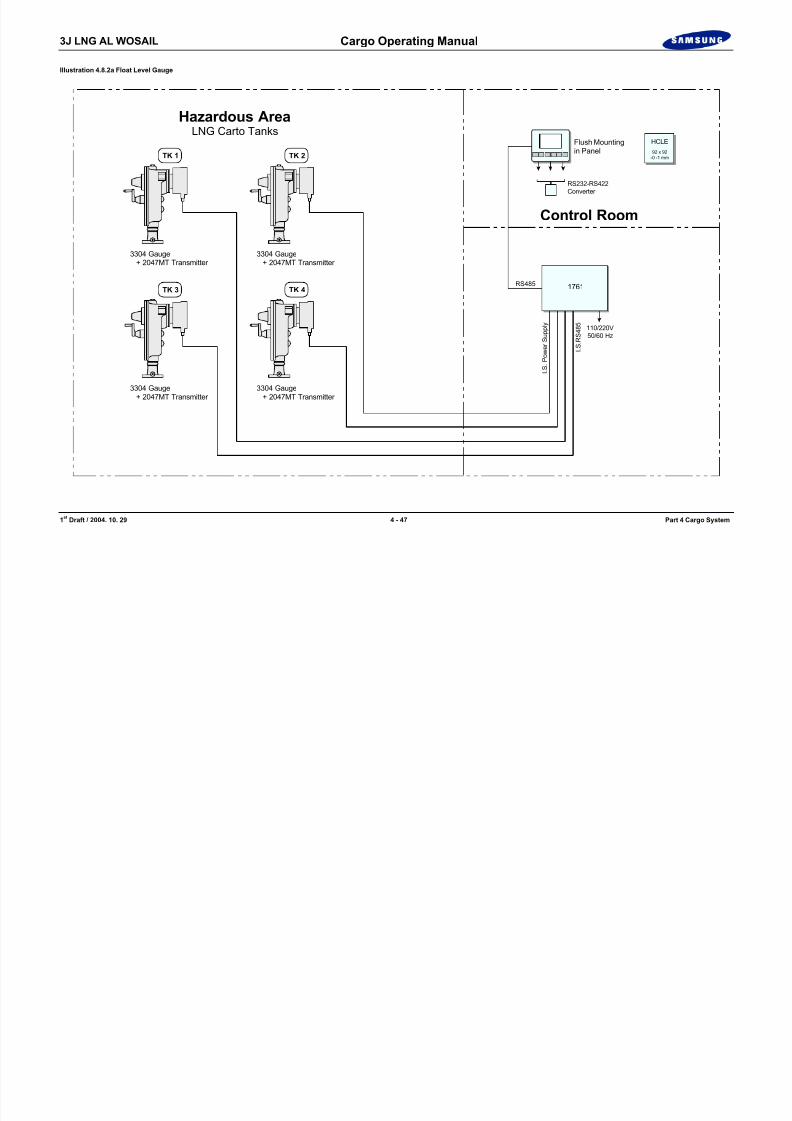
Illustration 4.8.2a Float Level Gauge
Hazardous AreaLNG Carto TanksFlush Mountingi P l
HCLE
8/12/2019 LNG Cargo Operating Manual
http://slidepdf.com/reader/full/lng-cargo-operating-manual 109/257
1 st Draft / 2004. 10. 29 4 - 47 Part 4 Cargo System
3304 Gauge + 2047MT Transmitter
TK 1
3304 Gauge + 2047MT Transmitter
TK 2
3304 Gauge + 2047MT Transmitter
TK 3
3304 Gauge + 2047MT Transmitter
TK 4
Control Room
RS232-RS422Converter
RS485
I . S
. P o w e r
S u p p
l y
I . S
. R S 4 8 5
110/220V50/60 Hz
in Panel
1761
92 x 92-0 -1 mm

8/12/2019 LNG Cargo Operating Manual
http://slidepdf.com/reader/full/lng-cargo-operating-manual 110/257
3J LNG AL WOSAIL Cargo Operating Manual
Non I.S Cabling to Control Room Equipment
A 3-core RS-485 screened data cable is required between the Fig. 1761 and 1084components. This should have a conductor size of 24 AWG (7/32 AWG) tinnedcopper conductors, with PVC jacket for extended cable life.
Cable Glands for 2047MT transmitter
Type : Flameproof EExd C / EExe Manufacturer / Model : CAPRI:848794
Illustration 4.8.2b Float Level Gauge
85
Forward AFT
2-holes 16 Dia. for M16 Screws
L o c a l R
e a d o u t W i n
d o w
Illustration 4.8.2c Float Level Gauge
114
60
114
Readout Window
Gauge Head
Handle in Stower and
Gauge Head Shown withoutRehois Transmission
Handle in XXXXXXX

8/12/2019 LNG Cargo Operating Manual
http://slidepdf.com/reader/full/lng-cargo-operating-manual 111/257
1 st Draft / 2004. 10. 29 4 - 49 Part 4 Cargo System
Material : BrassGland Size: 7Entry Thread Size : ¾” NPT
Nut across flat (A/F) : 30mmInner Sheath : 8.5 – 16mmOuter Sheath : 12 – 21mmArmour : 1.25
Inspection Chamber (Not Whessoe Supply)
12" Gate Valve(Not Whessoe Supply)
Tape Clamp
Plunger
Flat Body P.V.C.Closed Cell Rigid Foam
Float Recovery PlateMagnetic Stainless Steel
Multi-stand FlexibleStainless Steel Wire
Support(Not WhessoeSupply)
75 Maximum Clearance
755 Dia.
55
5 1 5
2 6 7
4 2 5 A p p r o x
1 9 0
. 5
1 5 2
. 5
2 5
7 6
5 " M i n
.
( 1 2 5 m m
)
Inspection PlateStating Operation of Crank Handle
Spring loaded automaticfloat lock up and datumplunger "PULL" to releasefloat
Tan k Top
Tank Bottom
1 5 1
12"(305 mm)
Support
Inspection Hatch(Not Whessoe Supply
Handle in Stower andGauge Warring Position
XXX Screw
Seal Washer 2" 150LE ASAFlat Faced Flame
Cushion Spring
Float Well(Not Whessoe Supply)(Shipyard XXXX andConstruct)
Tank Bottom15 Maximum Clearance
25 Dia. Holes on xxx Centresfor Complete Length of Float Well.Remove all XXXXXXXXXXXXXX
3J LNG AL WOSAIL Cargo Operating Manual
4.8.3 Trim-List Indicator
The ship is provided with a fixed Trim-List Indicator system for the CustodyTransfer System.
Specification
Maker : Kongsberg Maritime AS.
Type : Dual axes high precision inclinometer.

8/12/2019 LNG Cargo Operating Manual
http://slidepdf.com/reader/full/lng-cargo-operating-manual 112/257
1 st Draft / 2004. 10. 29 4 - 50 Part 4 Cargo System
Range : ± 2° trim, ± 5° list
Accuracy : List: ±0.0025 degrees (±0.05% FSO)Trim: ±0.001 degrees (±0.05% FSO)
Power supply : DC 24 V
Output : 4~20 mA (separate signals, common 0V)
Operating temperature range : -40 to +80°C
GeneralA dual axes high precision inclinometer is to be used for trim and list corrections.The inclinometer is a dual close loop instrumentation transducer, which canmeasure angles along two perpendicular directions. The sensing element is agalvanometer pendulum associated with an optical position sensor. The signaloutputs are proportional to the sine of the angles (component of the gravityacceleration). When the instrument is submitted to a certain angle, alpha, the
pendulous mass tends to move in the direction of the inclination. The position is
detected and converted into a current, which feeds back the galvanometer inorder to bring back the initial position. This current proportional to the measuredgravity passes through a precision resistor and provides the output signal. Anoutput amplifier allows low output impedance.
3J LNG AL WOSAIL Cargo Operating Manual
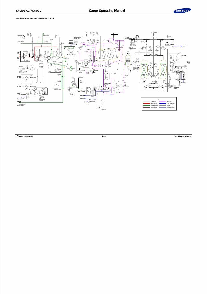
Illustration 4.9 Nitrogen Generator
MIT1A
AIT1A
MAH1A
FI
TP4 TP
3
AAHH1A
AAH1A
S
D N 5 0
O ( G
A S )
D N 5 0
D N 4 0
CONTROLPANEL
5.1A
440V 60H
PERMEATE VENTTO ATMOSHERE
OFF-SPEC.N2 VENT TO ATM.
400V 60H
FI1A
FAH1A

8/12/2019 LNG Cargo Operating Manual
http://slidepdf.com/reader/full/lng-cargo-operating-manual 113/257
1 st Draft / 2004. 10. 29 4 - 51 Part 4 Cargo System
PS2B
PI6
PI5
TAH2A
TIC2A
TE2A
TAH1A
PDI1A
PDI2A
TS1A
PI7
ME1A
TI3A
TI1A
PI4A
2A
PT5
PS2A
PS1A
PAL1A
PAH5
PAL5
WS-1A F1A F2A
EL HEATER
DN 40EH-1A
IV-4A
PI3A
IV-3A
IV-5A
V-5A V-7AV-6A
CALIBRATIONIV-7A
PCV-2A
V-4A
DN 25
FCV-2A
XV-4A
S
IV-5A
FCV-1A XV-2A
S
DN 25MS-1B
MS-1ACV-1A
XV-3A
DN 25
DN 25
DN 25
S
DN 50
DN 25IV-9
START/STOPSYSTEM B
START/STOP
INSTRUMENT BOARD
SYSTEM A
IV-23 IV-24V-21 V-22
V-22
V-23
V-13
V-14
V-21
DN 50
1AFIT
D N 1 5
Z E R O
S P A N
P C V - 3
A
D N 5 0
D N 2 5
TANKBUFFER
NITROGEN
BT-1
440V 60HzEL. SUPPLY
2 2 0 V 6 0 H z
E L
. S U P P L Y
2 2 0 V 6 0 H z
E L
. S U P P L Y
V-1A
V-16
TP1A
TP1B
V-1B
AD1A
AD2A
AD3A
SSS
TP21
TP26
TP23
PSV21
TP27
TP24
TP25
TP22
V-24
TP6
TP5
TP2
AD
4A
LA
4A
TP
8ATP
9ATP
10A
TP
7A
EL. SUPPLY400V, 60Hz
EL. SUPPLY400V, 60Hz
COMPRESSORASTARTER
PANELCONTROL
FILTERINLET
FILTEROIL
COOLER AFTER
SEP.OIL
COOLEROIL
M
WS-2A
V-16A
V-15A
S
FEED AIR COMPRESSOR FAC-1A
COOLING F.WINLET
COOLING F.WOUTLET
TO E/R BILGE
SET :1,300 kPa
COOLING WATER
KEY
COMPRESSED AIR
NITROGEN
DPSPS PI
TI TS
AD
4B
LA
4B
TP
8BTP
9BTP
10B
TP
7B
COMPRESSORB
STARTER
PANELCONTROL
FILTERINLET
FILTEROIL
COOLER AFTER
SEP.OIL
COOLEROIL
M
WS-2B
V-16B
V-15B
S
FEED AIR COMPRESSOR FAC-1B
DPS
PS PI
TI TS
PDA1A
TAH2B
TIC2B
TE2B
TAH1B
PDI1B
PDI2B
TS1B
TI3B
PS1B
PAL1B
WS-1B F1B F2B
EL HEATER
DN 40EH-1B
IV-4B
PI3B
IV-3B
IV-5B
V-5B V-7BV-6B
Z E R O
( G A S )
S P A N
P C V - 3
B
CONTROLPANEL
5.1B
440V 60HzEL. SUPPLY
AD1B
AD2B
AD3B
SSS
PDA1B
ME1B
MIT1B
TI1B
PI4B
AIT1B
MAH1B
FI2B
FI1B
FAH1B
AAHH1B
AAH1B
CALIBRATION IV-7B
PCV-2B
V-4B
FCV-2B
XV-4B
S
IV-5B
FCV-1B XV-2B
S
CV-1B
XV-3B
S
1BFIT
TO CONSUMERS
NITORGEN GENERATOR

8/12/2019 LNG Cargo Operating Manual
http://slidepdf.com/reader/full/lng-cargo-operating-manual 114/257
8/12/2019 LNG Cargo Operating Manual
http://slidepdf.com/reader/full/lng-cargo-operating-manual 115/257

8/12/2019 LNG Cargo Operating Manual
http://slidepdf.com/reader/full/lng-cargo-operating-manual 116/257

8/12/2019 LNG Cargo Operating Manual
http://slidepdf.com/reader/full/lng-cargo-operating-manual 117/257
8/12/2019 LNG Cargo Operating Manual
http://slidepdf.com/reader/full/lng-cargo-operating-manual 118/257
3J LNG AL WOSAIL Cargo Operating Manual
Illustration 4.11a Gas Detection System
C o
f f e r d a m
No.4Liquid Dome
El. Motor RM Cargo Machinery RM
No.4Gas Dome C
o f f e r d a m
C o
f f e r d a m
C o
f f e r d a m
Passage Way
C o
f f e r d a m
No.3Liquid Dome
No.3Gas Dome
Cargo Manifold (P)
No.2Liquid Dome
No.2Gas Dome
No.1Liquid Dome
No.1Gas Dome
A n
l y s
i n g
U n
i t
M a
i n P a n e
l
E l . E q u
i p .
R M
Stop Valve(To be locatedat safety area)
27
11 12
10
9
7
6
4
3
1
8 5 2
26
Ai S l

8/12/2019 LNG Cargo Operating Manual
http://slidepdf.com/reader/full/lng-cargo-operating-manual 119/257
1 st Draft / 2004. 10. 29 4 - 57 Part 4 Cargo System
g y
Passage Way
Cargo Manifold (S)
29 28
Air Supply
No.1VentMast
No.2VentMast
No.1 Cargo Tank
BowThr.Room
F.P. Tank
Bosun Store
H F O T a
n k ( C )
F W D W . B . T .
( P & S ) C
o f f e r d a m
C o
f f e r d a m
C o
f f e r d a m
C o
f f e r d a m
C o
f f e r d a m
No.2 Cargo TankNo.3 Cargo TankNo.4 Cargo Tank
Engine Room
A-Deck
B-Deck E . E . R
C-Deck
No.3VentMast
No.4VentMast
A n
l y s
i n g
U n
i t
Stop Valve(To be located at safetyarea on accomm. front wall)
Dia.20 CoomonOutlet
17
21 22
19 18
16
33 32 31 30
15 14 13
24
25
D i a
. 8 x
3 3 L i n e s
DrainSeparator Box (20, 34)
C/D
W. B. Tank W. B. Tank
C-Deck
Liquid DomeGas Dome
Cargo Tank
D-Deck
Cargo Mach.Room
Elec. Motor Room
Pipe Duct
P i p e
D u c t
A c c e s s T r u n
k P a
s s - w a
y P a s s - w a y
Collector Cone Filter
Gas DectionLinesCompression Type
BHD Union
Stop Valve with Filter (To be located at safetyarea on accomm. front wall) Gas Detection Lines
(Pass through Trunk)
Gas Detection Lines
Cargo Area GasAnalysing Unit
in Ele. Equip. Room
Air Supply
Typical Section
Section for Acc. Front Wall Typical Sec. for Cargo TK IBS/IS
Safety Line

8/12/2019 LNG Cargo Operating Manual
http://slidepdf.com/reader/full/lng-cargo-operating-manual 120/257
3J LNG AL WOSAIL Cargo Operating Manual
Illustration 4.12.1a Cargo Valve Hydraulic Lines
(CL401)
(CS400)(CS401) (CS403)
(CL402)(CL403) (CL400)(CL407)(CG708)
(CS308)
(CL011) (CL031)
(CL200) (CL207)
(CL102) (CL103)(CL101)
(CL100) (CL107)
(CL041)(CL02 1) (CG 071)
MANIFOLD(P)
* * * * *
* * *
**
* *
* *** *
(CS301)(CS300) (CS303)
* **
(CL301) (CL303)
**
(CG702)
*
(CL202)(CL203)(CL201)
* **(CL075)
#
*

8/12/2019 LNG Cargo Operating Manual
http://slidepdf.com/reader/full/lng-cargo-operating-manual 121/257
1 st Draft / 2004. 10. 29 4 - 59 Part 4 Cargo System
TRUNK DECK
ACCUMULATOR STAND Accumulator : 9sets (50l)
(CG904) (CG925)(CG918)
(CL300) (CL307) (CS103) (CS107) (CS108)
NO.1C SOL.V/V BOX
NO.2C SOL.V/V BOX
ACC
ACC
P
P
T
CARGO MACHINERY ROOM
MANIFOLD(S)
(CL012) (CL032) (CL042)(CL022 ) (CG 072)
SIDE PASSAGE
SIDE PASSAGE
H.P.P ROOMUPP. DECK
TRUNK DECK TRUNK DECK TRUNK DECK
CLEAN TANK (1900 LTR)
* * *
* : REMOTE HYD. CONTROL / THROTTLING
# : REMOTE HYD. CONTROL / EMERGENCY SHUTDOWN
DIRTY TANK (1250 LTR) P
ACC
PP PP
P
TT TTT
(CG902)(CG901)(CG900)
(CG917)
(CG903)
(CS071)
(CS407) (CS408) (CS702)(CS100) (CS101)
**
(CS203) (CS207) (CS208)
*(CS200) (CS201)
**
(CG930)
#
#*
STOP V/V

8/12/2019 LNG Cargo Operating Manual
http://slidepdf.com/reader/full/lng-cargo-operating-manual 122/257
3J LNG AL WOSAIL Cargo Operating Manual
2) Emergency control of the solenoid valves.a) In case of electric power failure
Push the manual override on the solenoid valves(right :close, left: open)
Open/shut valves : push the manual override until obtaining acorresponding valve position (full close or full open).
Intermediate valve : push the manual override until obtaining acorresponding valve position.
b) In case of lack of hydraulic Pressure Close the main isolating valves. Connect the emergency hand pump with connection block on the
pressure common line and return common line
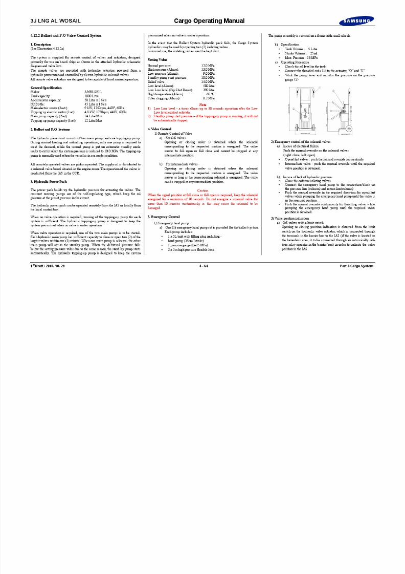
The whole is secured on a frame with small wheels.
b) Specification Tank Volume : 5 Litre Stroke Volume : 25ml Max. Pressure : 13 MPa
c) Operating Procedure Check the oil level in the tank. Connect the threaded ends to the actuator, “O” and “S” Work the pump lever and monitor the pressure on the pressure
gauge

8/12/2019 LNG Cargo Operating Manual
http://slidepdf.com/reader/full/lng-cargo-operating-manual 123/257
1 st Draft / 2004. 10. 29 4 - 61 Part 4 Cargo System
pressure common line and return common line Push the manual override on the solenoid valves (right: close, left:
open) while pumping the emergency hand pump until acorresponding valve position is obtained.
Open/shut valve : full close or full open position. Intermediate valve : full close / full open or any required valve
position
3) Valve position indicationa) O/S valves with a limit switch
Opening or closing position indication is obtained from the limitswitch on the hydraulic valve actuator, connected through theintrinsically-safe type relay repeater in the barrier box, wherevoltage-free contacts are used to indicate the valve position in theIAS.
b) Intermediate remote controlled valvesOpening or closing position indication is obtained from the
potentiometer on the hydraulic actuators in order to indicate thevalve position in the IAS.- Potentiometer signal : Converted to 4 ~ 20mA signal through IS
R/I converter in the barrier box.
4) Valve Operating time adjustmentValve operating time adjustment can be adjusted using the flow controlvalve installed in each solenoid valve block.
5. Emergency Control
1) Emergency hand pumpa) two (2) emergency hand pump sets are provided for the ballast
system.Each pump includes,
1 x 5litre tank with filling plug including - hand pump (25cm 3/stroke) 1 pressure gauge (0 – 25 MPa) 2 x 5m high pressure flexible hose
3J LNG AL WOSAIL Cargo Operating Manual
8/12/2019 LNG Cargo Operating Manual
http://slidepdf.com/reader/full/lng-cargo-operating-manual 124/257
1 st Draft / 2004. 10. 29 4 - 62 Part 4 Cargo System
Blank Page

8/12/2019 LNG Cargo Operating Manual
http://slidepdf.com/reader/full/lng-cargo-operating-manual 125/257
8/12/2019 LNG Cargo Operating Manual
http://slidepdf.com/reader/full/lng-cargo-operating-manual 126/257
3J LNG AL WOSAIL Cargo Operating Manual
b) Intermediate remote controlled valvesOpening or closing position indication is obtained from the
potentiometer on hydraulic actuators and the signal is converted toa 4 ~ 20mA signal through an R/I converter (if the valve is locatedin the hazardous area, the R/I converter is an intrinsically safe type)in the barrier box in order to indicate the valve position in the IAS.
4) Valve Operating time adjustmentValve operating time can be modified by adjusting the flow reducerinstalled on each solenoid valve block
NoteThe operating time depends on the length of the yard piping and oil
8/12/2019 LNG Cargo Operating Manual
http://slidepdf.com/reader/full/lng-cargo-operating-manual 127/257
1 st Draft / 2004. 10. 29 4 - 65 Part 4 Cargo System
e ope at g t e depe ds o t e e gt o t e ya d p p g a d ocharacteristics. The operating time is set at ambient temperature, however, theactual operating time is strongly influenced by the actual ambient temperatureand the oil characteristic, particularly if the distance between actuator andsolenoid control valve is long.
3J LNG AL WOSAIL Cargo Operating Manual

8/12/2019 LNG Cargo Operating Manual
http://slidepdf.com/reader/full/lng-cargo-operating-manual 128/257
1 st Draft / 2004. 10. 29 4 - 66 Part 4 Cargo System
Blank Page

8/12/2019 LNG Cargo Operating Manual
http://slidepdf.com/reader/full/lng-cargo-operating-manual 129/257
8/12/2019 LNG Cargo Operating Manual
http://slidepdf.com/reader/full/lng-cargo-operating-manual 130/257
3J LNG AL WOSAIL Cargo Operating Manual
Illustration 4.12.4a Ship-Shore Link
ELEC. EQUIPMENT ROOMSHIP SHORE LINK ENCLOSURE
CARGO CONTROL CONSOLE
CCC4 CCC9
CARGO CONTROL ROOM SHIP SIDE PORT ON DECK FR100 ACCOMODATIONUPP DK FR46
MLM DESKTOP PC
FO & ELSYSTEMSELECTORMODULE
FO PORT STARBOARDSELECTORMODULE
PRESSTO
TEST
INHIBIT
RESET
INHIBIT
RESET
LAMPTEST
P O R T S TB D
HEALTHY
PRESSTO
TEST
LAMPTEST
SYSTEMFAULT
SELECTEDFIBRE OPTICELECTRIC
FIBRE OPTICSYSTEM
SYSTEMSELECTOR
NORMAL
NORMALSHIP -> SHORE
ABNORMAL
E SD SY ST EM T el ep ho ne SY ST EM
HEALTHY ESDHEALTHY
LOADING ARMTRIP 1HEALTHY
LOADING ARMTRIP 2HEALTHY
SHORE RECEIVINGHIGHLEVELHEALTHY
SELECTED
ELECTR ICA LS Y STEM TR IP INP U TS
ITTCANNON
PORT

8/12/2019 LNG Cargo Operating Manual
http://slidepdf.com/reader/full/lng-cargo-operating-manual 131/257
1 st Draft / 2004. 10. 29 4 - 69 Part 4 Cargo System
CCC4 CCC9
SHIP SIDE STBD ON DECK FR100
220VAC1X2X2.5
PSU
PSU
MODEN
JB-INT
HOT-LINE TELEPHONE
HOT-LINETELEPHONE(SPARE)
GENERALALM
PABXTELEPHONE
PUBLICTELEPHONE
RJ11 RJ11
ESDS (AMRI-SEIL)
ELECTRIC ESD SHIP SHORE/SHORE-SHIPFO ESD SHIP SHORE/SHORE-SHIP
IAS (YAMATAKE)
COMMON ALARM
AC 220V MAIN NORMAL POWER24V DC BACKUP SUPPLY, 8A MAX
G EN ER AL A LM G EN ER AL A LM
220VAC EM'CY POR1X2X2.5
SERIALC/OSWITCH
RJ11
POWERSUPPLY MODULE
FO CONTROL& ALARMMODULE
ELECTRICSYSTEMCONFIGURATIONMODULE
B
A
D
E
CB
A
D
E
CB
A
D
E
CB
A
D
E
C
SW 1
P YL E I TTCANNON
MIYAKI
SW 2 SW 3 SW 4 SW 5
E SD S Y ST E MS E LE C T
H O TPH O N E P R IVATELIN E
SW 7
TE LC H1 TEL CH2 TE LC H3
B
A
D
E
C
SW 6
TELCH4
NORMAL
TRIPS ACTIVE SHIP TO SHIPREVERSE CONNECTION
ACMAINSSUPPLY
ABNORMAL
PRESSTO
TEST
AUDIO ALARM
PRESSTO
TESTCIRCUIT
TEST
FO ESDMODULE
SHORE -> SHIP
ABNORMAL
NORMAL
ABNORMAL
ESD
C H 1 C H 2 C H 3 C H 4
SIGNALFAULT
9w D
ITTCANNON
STBD
RJ11
3J LNG AL WOSAIL Cargo Operating Manual
Illustration 4.12.4b Ship-Shore Optic Fibre Transmission and ESD Link System Schematic
From Mooring Tension Monitor Computer From Mooring Load Monitor Display
Shore Side Ship Side
MooringLoad
Monitor Modem
PublicPhone
PlantPhone
HotLine
Phone
MooringLoad
Monitor Modem
PublicPhone
Ship'sExch.
Phones
HotLine
Phone

8/12/2019 LNG Cargo Operating Manual
http://slidepdf.com/reader/full/lng-cargo-operating-manual 132/257
1st
Draft / 2004. 10. 29 4 - 70 Part 4 Cargo System
Shore Side OpticalCable Reel50 - 100m
Starboard SideShip Connector
Shore SideConnector
Port SideShip Connector
el I/FUnit
el I/FUnit
el I/FUnit
el I/FUnit
Multiples UnitElectric / Optical
Interface
EmergencyShutdown Unit
With E/O Interface
Power Supply UnitControl Alarm
Module Spare
Yuken Plant EmergemcyShutdown Control System
el I/F
Unit
el I/F
Unit
el I/F
Unit
el I/F
Unit
Multiples UnitElectric / Optical
InterfacePort / Stb.d Section
EmergencyShutdown Unit
With E/O Interface
Power Supply UnitControl Alarm
Module
Yuken Plant EmergemcyShutdown Control System
Spare

8/12/2019 LNG Cargo Operating Manual
http://slidepdf.com/reader/full/lng-cargo-operating-manual 133/257

8/12/2019 LNG Cargo Operating Manual
http://slidepdf.com/reader/full/lng-cargo-operating-manual 134/257

8/12/2019 LNG Cargo Operating Manual
http://slidepdf.com/reader/full/lng-cargo-operating-manual 135/257
3J LNG AL WOSAIL Cargo Operating Manual
Battery LOW Incoming Ring signalling for the for the channel selected
An intrinsically safe handset allows all 3 telephone channels includinghotline to be tested for Tx and Rx s ignalling and speech paths.The whole unit allows a full pre-berthing test to be carried out from theelectrical telephone and ESD inputs via the cable, up to the shipside
combination connector, mounted in the connector box, without the needfor the vessel to be along side a jetty.The unit is powered using rechargeable Lithium ION batteries and canoperate for a minimum of 1 hour.The unit weight is approximately 14 kg with carrying handles for 1 or 2
persons.

8/12/2019 LNG Cargo Operating Manual
http://slidepdf.com/reader/full/lng-cargo-operating-manual 136/257
1st
Draft / 2004. 10. 29 4 - 74 Part 4 Cargo System
5. Approvals
The system is designed for ship or shore use, and complies with IEC-945 forshipboard equipment. The equipment complies with SIGTTO July 1987
recommendations. The system is inherently intrinsically safe and has receivedABS approval on the first system delivered by Seatechnik-NFI.
6. PABX/Public Telephones
Two standard type European telephones for 48VDC operation with off-hookline impedance 600 ohm, on hook line impedance 6000 ohm will be supplied.Line termination shall be by RJ11 standard type socket outlet(USA/International). The telephones may be mounted on the console. They will
be connected into the fibre-optic ship-shore link cabinet and switched byinternal circuitry within the fibre-optic ship-shore link cabinet. The SystemSelector Module selects the phone routing by use of the selector switch on thefront panel within the SSL cabinet.
4.13.4.4 Pneumatic Systems
Two quick-connect male/female umbilical pneumatic connectors are provided atmain deck level underneath the manifolds for use with the similar systems usedat Ras Laffan and other terminals. These directly trip the loading valves on
pressure loss and are sensed by the Yuken ESD system.

8/12/2019 LNG Cargo Operating Manual
http://slidepdf.com/reader/full/lng-cargo-operating-manual 137/257
3J LNG AL WOSAIL Cargo Operating Manual
3) Mooring PatternsA graphical representation of the preferred mooring pattern may becreated, saved edited, recalled or deleted for each jetty. Dragging a linefrom a hook to a fairlead position draws a mooring line. Right-clickingon the fairlead allows a choice of which line to remove. Continuedrawing or deleting lines for each active hook until the mooring patternis completed. Once complete the pattern can be saved for this jetty

8/12/2019 LNG Cargo Operating Manual
http://slidepdf.com/reader/full/lng-cargo-operating-manual 138/257
1st
Draft / 2004. 10. 29 4 - 76 Part 4 Cargo System
Creating and Saving a Mooring Pattern
Communications StatusCommunication between the Shore Data Monitoring System and the Mooring
Line monitoring system is via the serial port.
Communication Status
The communications status indicator will change from a Red “Not Connected” toa Green “Connected” when a valid data packet is received from the shore-basedsystem. If the connection to shore is lost the status will return to a red “NotConnected”. Data will be marked as bad (grey) or old (navy) depending on thecondition of the last packet received.

8/12/2019 LNG Cargo Operating Manual
http://slidepdf.com/reader/full/lng-cargo-operating-manual 139/257
3J LNG AL WOSAIL Cargo Operating Manual

8/12/2019 LNG Cargo Operating Manual
http://slidepdf.com/reader/full/lng-cargo-operating-manual 140/257
1st
Draft / 2004. 10. 29 4 - 78 Part 4 Cargo System
Blank Page
3J LNG AL WOSAIL Cargo Operating Manual
Illustration 4.13.1a Cargo Tank Relief Valves
Specification No. of sets: 8Type: Pilot OperatedSet pressure: 25 kPaGClosing pressure: 22 kPaGRequired capacity: 22,000 Nm 3/hRelieving capacity: 28,260 Nm 3/h
Test gag
Adjust screwExhaust tube
Illustration 4.13.2b Insulation IBS & IS Relief Valves
Specification No. of sets: 16Type: Pilot OperatedSet pressure: 3 kPaG (For IBS), 3.5 kPaG (For IS)Closing pressure: 1.8 kPaG (For IBS), 2.1 kPaG (For IS)Required capacity: 228 Nm 3/h (For IBS), 228 Nm 3/h (For IS)Relieving capacity: 420 Nm 3/h (For IBS), 481 Nm 3/h (For IS)
Test gag
Adjust screw
Pilot Valve

8/12/2019 LNG Cargo Operating Manual
http://slidepdf.com/reader/full/lng-cargo-operating-manual 141/257
1st
Draft / 2004. 10. 29 4 - 79 Part 4 Cargo System
For manual lifting deviceconnection Rc1/2
Diaphragm
Check plate
Pilot Valve
Nozzle
Set plateDiaphragm retainer
For test ConnectionRC 1/2
Supply pipe
For manual lifting deviceconnection Rc1/2
Diaphragm
Check plate
Diaphragm retainer Diaphragm
Nozzle
For test ConnectionRC 1/2
Vent Tube
Supply Pipe
Exhaust Tube

8/12/2019 LNG Cargo Operating Manual
http://slidepdf.com/reader/full/lng-cargo-operating-manual 142/257
3J LNG AL WOSAIL Cargo Operating Manual
Illustration 4.13.2a Cargo Tank Relief Valves (REC131-S1(E))
Test gag
Lifting fork
Adj. screwlock nut
Adjusting screw
Shaft
Plug
lock nut
Cap
Illustration 4.13.2b Cargo Tank Relief Valves (REC131-S1(N))
Test gag
Cap
Adj. screwlock nut
Adjusting screw
Plug
Lock nut
Cap nut

8/12/2019 LNG Cargo Operating Manual
http://slidepdf.com/reader/full/lng-cargo-operating-manual 143/257
1st
Draft / 2004. 10. 29 4 - 81 Part 4 Cargo System
S
S
Adj. lock bolt
Disc
Nozzle
Adj. ring
Lever
Plug
Spring
Stud bolt & nut
Guide
Spindle
S
S
Adj. lock bolt
Disc
Nozzle
Adj. ring
Lever
Plug
Stud bolt & nut
Spring
Spindle
Guide
3J LNG AL WOSAIL Cargo Operating Manual
Part 5 : Cargo Auxiliary and Ballast System 5.1 Temperature Monitoring System ............ ............ ............ ........... ........ 5 - 3 5.2 Insulation Space Nitrogen Control System.............. ............ ............ .. 5 - 6 5.3 Cofferdam Glycol Heating System... ........... ............ ............ ............ 5 - 10
5.3.1 Glycol Water Heater..............................................................5 - 10 5.3.2 Cofferdam Glycol Heating System............ ........... ............ .... 5 - 12 5.3.3 Hull Ventilation.....................................................................5 - 14
5.4 Cargo Machinery FW Cooling System........... ............ ............ ......... 5 - 16 5.5 Ballast System .................................................................................5 - 18 5.6 Fire Fighting System........................................................................5 - 20
5.6.1 Fire and Deck Wash System ........... ............ ............ ............ .. 5 - 20 5.6.2 Water Spray System..............................................................5 - 22 5.6.3 Dry Powder System .............................................................. 5 - 26 5.6.4 CO 2 System........................................................................... 5 - 30 5.6.5 Fire Detection System...........................................................5 - 32

8/12/2019 LNG Cargo Operating Manual
http://slidepdf.com/reader/full/lng-cargo-operating-manual 144/257
1st
Draft / 2004. 10. 29 Part 5 Cargo Auxiliary and Ballast System
Part 5Cargo Auxiliary and Ballast System
3J LNG AL WOSAIL Cargo Operating Manual
Illustration 5.1a Temperature Monitoring System (Secondary Barrier, Trunk Deck and Duct keel)
AFT Bulkhead
STARBOARD PORTTE6A
TIALCTn01
TE6B
TE5B
TIALCTn02
TE5A
AFT Bulkhead
STARBOARD PORTTE21
TIALCTn07
TE20
TIALCTn08

8/12/2019 LNG Cargo Operating Manual
http://slidepdf.com/reader/full/lng-cargo-operating-manual 145/257
1st
Draft / 2004. 10. 29 5 - 1 Part 5 Cargo Auxiliary and Ballast System
TE4B
TIALCTn03
TE4A
TE
2A
TIALCTn05
TE
2B
TE3B
TIALCTn04
TE3A
TE10A
TIALCTn19
TE10B
TE7A
TIALCTn16
TE7B
TE8A
TIALCTn06
TE8B
TE9A
TIALCTn18
TE9BTE
1A
TIALCTn17
TE1B
Duct Keel
TE19
TIALCTn19
TE18
TIALCTn10
TE17
TIALCTn09
Key
- Temperature sensors in primary space : TE 1A, TE 1B (1 Ffor service and 1 for spare)
- Temperature sensors on secondary barrier (7 for service 7 for spare) : TE 2A, TE 2B, TE 3A, TE 3B, TE 4A, TE 4B, TE 5A, TE 5B, TE 6A, TE 6B, TE 7A, TE 7B, TE 8A, TE 8B
- Temperature in primary barrier : TE 9A, TE 9B, TE 10A, TE 10B (1 for service and 1 for spare)
Key
- Temperature sensors on double hull (3 in duct keel, 2 in trunk deck) : TE 17, TE 18, TE 19, TE 20, TE 21
3J LNG AL WOSAIL Cargo Operating Manual
Illustration 5.1b Temperature Monitoring System (Cofferdam)
AFT Bulkhead
STARBOARD PORT
FWD Bulkhead
PORT STARBOARD
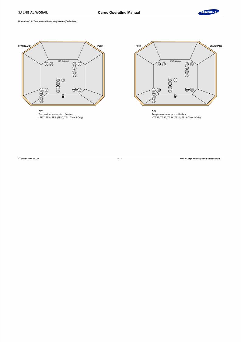
8/12/2019 LNG Cargo Operating Manual
http://slidepdf.com/reader/full/lng-cargo-operating-manual 146/257
1st
Draft / 2004. 10. 29 5 - 2 Part 5 Cargo Auxiliary and Ballast System
Key
Temperature sensors in cofferdam- TE 7, TE 8, TE 9 (TE10, TE11 Tank 4 Only)
TE10
TE7
TE9
TE11
AFT Bulkhead
TE8
TIALCH405
TTALCH106
TIALCH204
TIALCH304
TIALCH404
TIALCH107
TIALCH205
TIALCH305
TIALCH406
TIALCH108
TIALCH408
TIALCH206
TIALCH306
TIALCH407
Key
Temperature sensors in cofferdam- TE 12, TE 13, TE 14 (TE 15, TE 16 Tank 1 Only)
TE15
TE12
TE14
TE16
FWD Bulkhead
TE13
TIALCH102
TTALCH101
TIALCH201
TIALCH301
TIALCH401
TIALCH103
TIALCH202
TIALCH302
TIALCH402
TIALCH104
TIALCH105
TIALCH203
TIALCH303
TIALCH403
3J LNG AL WOSAIL Cargo Operating Manual
Part 5 : Cargo Auxiliary and Ballast System
5.1 Temperature Monitoring System
1. General Description(See Illustration 5.1a, 5.1b)
Monitoring equipment is provided in the CCR for the secondary insulation barrier and inner hull temperatures, to give warning in case of failure ofinsulation or leakage of the primary insulation barrier.
Each sensor is of the PT100 resistance type. The sensors are installed in thesecondary insulation barriers and alongside the inner hull associated with eachcargo tank. The temperature range of each sensor is: -200 ° C to +100 °C.
The secondary insulation barrier thermocouples (sensors) are installed at 14 points around the space as shown, all 14 of them in pairs.

8/12/2019 LNG Cargo Operating Manual
http://slidepdf.com/reader/full/lng-cargo-operating-manual 147/257
1st
Draft / 2004. 10. 29 5 - 3 Part 5 Cargo Auxiliary and Ballast System
p p p
For the inner hull temperature measurement there are 11 sensors in each tank.Three(3) is located along the bottom of the tank in the pipe duct and two(2)sensors is located in the trunk deck. In the cofferdam spaces there are 3temperature sensors on each of the forward and aft bulkheads.
In the No.1 cofferdam space there is 2 temperature sensors added on forward bulkhead.
In the No.4 cofferdam space there is 2 temperature sensors added on aft bulkhead.
The temperature measurements are indicated, for each sensor in service, in theCCR via the IAS. Recording of these temperatures is also available via the IAS.
The thermocouples for the secondary insulation barrier sensors’ alarm points areset at -120 °C.
The thermocouples for the inner hull sensors’ alarm points are set at 0°C.
Trend curves from the received data can be plotted via the IAS in the CCR.
3J LNG AL WOSAIL Cargo Operating Manual
8/12/2019 LNG Cargo Operating Manual
http://slidepdf.com/reader/full/lng-cargo-operating-manual 148/257
1 st Draft / 2004. 10. 29 5 - 4 Part 5 Cargo Auxiliary and Ballast System
Blank Page

8/12/2019 LNG Cargo Operating Manual
http://slidepdf.com/reader/full/lng-cargo-operating-manual 149/257

8/12/2019 LNG Cargo Operating Manual
http://slidepdf.com/reader/full/lng-cargo-operating-manual 150/257
3J LNG AL WOSAIL Cargo Operating Manual
Fig. 1 Barrier Space N2 Pressurisation Control
N2 HEADERCONTROL
IAS
PID PID[REVERSE]
PV
<CT004>
IBS N2 SUPPLYCONTROL
[REVERSE]
PV
<CTn51S>
SP(SPHILM:1.15)
HIGH/LOWLIMIT
PID
IBS N2 EXHAUSTCONTROL
[DIRECT]
<CTn51E>
SP(SPHILM:1.15)
HIGH/LOWLIMIT
PV
PID
IS N2 SUPPLYCONTROL
[REVERSE]
PV
<CTn56S>
SP(SPHILM:0.8)
HIGH/LOWLIMIT
PID
IS N2 EXHAUSTCONTROL
[DIRECT]
<CTn56E>
SP(SPHILM:0.8)
HIGH/LOWLIMIT
CTn52x - y
IS/IBSDIFF.PRESS
PV

8/12/2019 LNG Cargo Operating Manual
http://slidepdf.com/reader/full/lng-cargo-operating-manual 151/257
1 st Draft / 2004. 10. 29 5 - 7 Part 5 Cargo Auxiliary and Ballast System
LIQUIDDOME I B
S I S
I B S
I S
TO OTHERCARGO TANK
TO VENT MAST
N2 EXH. LINE
N2 SUPP. LINE
N2 HEADER
N2BUFFER TANK
IBS SUPP.V/V
IS SUPP.V/V
IBS EXH.V/V
IS EXH.V/V
IS/IBSDIFF.PRESS
<CT005> <CT041>
GASLINE
<CTn54> n = 1~4 <CTn55> <CTn51I> <CTn56I> <CTn58> <CTn59> <CTn58> <CTn59>
x y
PT
PT PT PTDPT
3J LNG AL WOSAIL Cargo Operating Manual

8/12/2019 LNG Cargo Operating Manual
http://slidepdf.com/reader/full/lng-cargo-operating-manual 152/257
1 st Draft / 2004. 10. 29 5 - 8 Part 5 Cargo Auxiliary and Ballast System
Blank Page
3J LNG AL WOSAIL Cargo Operating Manual
Illustration 5.3.1a Glycol Water Heater
Main Line
Key
Stand-by Line Air Line
F.W Line
Top of Electric Motor Room
Glycol Water Expansion Tank
(1 m3)
Glycol Reservoir (4.5 m3)
To be Located in Safe AreaFlame Screen
3 6 FG
H 6 3 2 FGH635F
Air Separator
Sett.0.6 MPa
GH701F
S t e a m
I n l e t

8/12/2019 LNG Cargo Operating Manual
http://slidepdf.com/reader/full/lng-cargo-operating-manual 153/257
1 st Draft / 2004. 10. 29 5 - 9 Part 5 Cargo Auxiliary and Ballast System
F r o m
C o m p .
A i r
F r o m
F r e s h W a t e r
P n e u m a t i c
P u m p
( 2 m
3 / h x
1 0 M T H )
WG542F
Mixing Tank(0.2 m3, 750L)
G H 6 3 3 F
GH638F
L.O
No. 1 Glycol Water Circulating Pump
(30 m3/h x 30 MWC)
[Electric Motor Room]
G H 6 3 4 F
G H 6 3 G
GH612F GH611F GH609F
GH610F
GH608F GH602F Air Separator
Air Separator
G H 6 1 5 F
G H 6 1 4 F
G H 6 1 3 F
G H 6 1 6 F
AR551F
G H 6 3 7 F
G H 6 3 1 F
GH606F N-1
N-6
N-2
GH604F
Sett.0.6 MPa
GH701FGH601F
No. 2 Glycol Water Circulating Pump
(30 m3/h x 30 MWC)
GH628F GH627F GH625F
GH626F
GH624F GH618FGH622F N-1
N-6
N-2
GH620F
GH702F G H 6 3 9 F
S i g h t G l a s s
GH617F
S t e a m
I n l e t
Condensate
Condensate
No.2 GlycolWater Heater
No.1 GlycolWater Heater
A1 A2R2R1
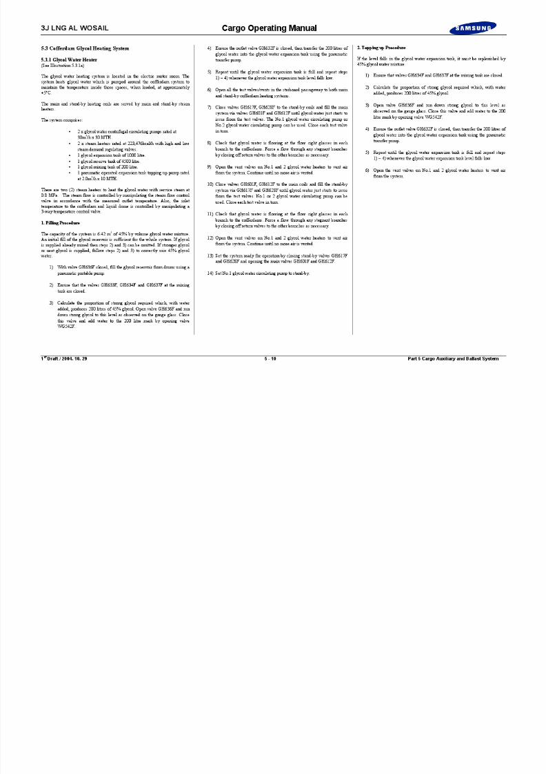
8/12/2019 LNG Cargo Operating Manual
http://slidepdf.com/reader/full/lng-cargo-operating-manual 154/257

8/12/2019 LNG Cargo Operating Manual
http://slidepdf.com/reader/full/lng-cargo-operating-manual 155/257
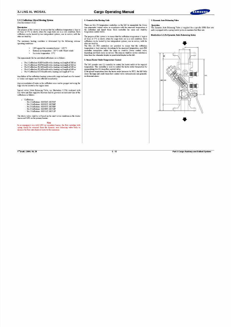
8/12/2019 LNG Cargo Operating Manual
http://slidepdf.com/reader/full/lng-cargo-operating-manual 156/257

8/12/2019 LNG Cargo Operating Manual
http://slidepdf.com/reader/full/lng-cargo-operating-manual 157/257
3J LNG AL WOSAIL Cargo Operating Manual
5.3.3 Hull Ventilation(See Illustration 5.3.3a)
The ballast tanks 1 to 4, the cofferdams, trunk space and areas surrounding theliquid domes are inspected on a regular basis in order to check for cold spots,condition of the paint work and general inspection of piping, fittings and valves.In general it should be expected to inspect one cofferdam area per month.
The compartments to be entered must first be ventilated. The ship is fitted with amechanical exhaust fan for the pipe duct which is situated on the aft pipe ducttrunk top. Above the forward pipe duct trunk top is a natural supply ventilatorwhich must be opened before starting the exhaust fan.
When it is judged that the atmosphere inside the cofferdams is safe, entry can bemade. The entry personnel must take with them a personal O 2 meter. The
portable detector head should be lowered down to each level as they proceed.
NoteIf it has been found that the nitrogen consumption has increased beyond

8/12/2019 LNG Cargo Operating Manual
http://slidepdf.com/reader/full/lng-cargo-operating-manual 158/257
1 st Draft / 2004. 10. 29 5 - 14 Part 5 Cargo Auxiliary and Ballast System
normally acceptable levels, then added precautions should be observed before
entering the cofferdam spaces.
Each cofferdam is fitted with a manhole cover located on the starboard side,which may be removed and a portable gas freeing fan fitted to which is attacheda flexible ducting. This is also the location that any injured person can beremoved from the cofferdam space.
The port and starboard side of each cofferdam is provided with access manholesfor exhaust of air.
There are two (2) portable supply fans for the cofferdam spaces which give atotal air volume flow of 5,000 m 3/h.
The passageway areas, port and starboard, are equipped with a mechanicalexhaust fan located midships, and two natural supply ventilators forward and aft.
The trunk deck areas have four manhole covers, two forward and two aft. The aftmanholes are used to fit a portable supply fan for gas freeing, with the forwardmanholes being removed for exhausting during gas freeing.
3J LNG AL WOSAIL Cargo Operating Manual
Illustration 5.4a Auxiliary Fresh Water Cooling System
LO Cooler for No.1 HDC
WF512F
WF519
The vent to be connected
at the highest point on thecooling return line
Motor Room
LO Cooler for No.2 HDC
WF511F
WF514F
WF513F
40
40
40

8/12/2019 LNG Cargo Operating Manual
http://slidepdf.com/reader/full/lng-cargo-operating-manual 159/257
1 st Draft / 2004. 10. 29 5 - 15 Part 5 Cargo Auxiliary and Ballast System
Drain Cooler (50 m3/h)
Vent(A)WF501F
Drain(B)
7-I
7-II
Cargo Machinery Room
WF502F
LO Cooler for No.1 LDC
WF516F
8 0 8 0
8 0 8 0 1 0 0
1 0 0
6 5 6 5
WF515F
LO Cooler for No.2 LDC
P - w
a y
W e a t h e r P a r t
WF518F
WF517F
From E/R
Fresh Water Line
Key
125
125
40
40
40
40
40
S U S 3 0 4 S C H I O S
3J LNG AL WOSAIL Cargo Operating Manual
5.4 Cargo Machinery FW Cooling System(See Illustration 5.4a)
1. General
The cargo machinery cooling fresh water system is provided by two CargoMachinery fresh water cooling pumps located in the engine room. The CargoMachinery fresh water system is cooled by the Central Cooling system in the
engine room..
Specification
Cargo Machinery Cooling FW PumpMaker: Shinko Ind. Ltd.Type: Vertical, centrifugal, electric motor driven
Number of sets: 2Rated output: 80 m 3/h X 40 MTH
Each pump can be started locally or remotely. For the remote control of eachpump the pump control position should be set to remote on the motor starter

8/12/2019 LNG Cargo Operating Manual
http://slidepdf.com/reader/full/lng-cargo-operating-manual 160/257
1 st Draft / 2004. 10. 29 5 - 16 Part 5 Cargo Auxiliary and Ballast System
pump, the pump control position should be set to remote on the motor starter panel. Also, if the control position is not in remote position, the stand-by logiccannot be activated on the IAS. If the following conditions are met, the IASactivates the stand-by logic control function:
Control position of each pump is set to Remote. The stand-by control mode is set to AUTO on the schematic display.
The FW cooling system is used to serve the following equipment
HD compressor LO coolers and air cooler of electric motor. LD compressor LO coolers. Cargo compressor room steam drain cooler.
2. Operating Procedures
One auxiliary cooling FW pump is normally required to meet the system coolingcapacity.
1) Open the inlet and outlet valves on both Cargo Machinery cooling FW pumps.
2) Open the valves on the respective system to be cooled i.e. HD compressorLO cooler and motor air cooler, LD compressor LO cooler, and steamdrain cooler. Check for leaks.
3) Select one of the Cargo Machinery cooling FW pumps on local controland start the pump. Check that the system pressures are normal.
4) Select the other pump on stand-by.
5) Stop the running pump and ensure that the stand-by pump cuts in.
6) Return the pumps to their original running condition of one pump runningand the other on stand-by.
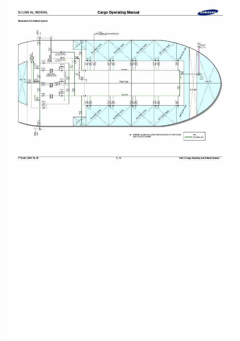
8/12/2019 LNG Cargo Operating Manual
http://slidepdf.com/reader/full/lng-cargo-operating-manual 161/257

8/12/2019 LNG Cargo Operating Manual
http://slidepdf.com/reader/full/lng-cargo-operating-manual 162/257

8/12/2019 LNG Cargo Operating Manual
http://slidepdf.com/reader/full/lng-cargo-operating-manual 163/257

8/12/2019 LNG Cargo Operating Manual
http://slidepdf.com/reader/full/lng-cargo-operating-manual 164/257
3J LNG AL WOSAIL Cargo Operating Manual
Illustration 5.6.2a Water Spray System
Engine Room
No.4Liquid Dome
El. Motor RM Cargo Machinery RM
No.4Gas Dome
Passage Way
Passage Way
No.3Liquid Dome
No.3Gas Dome
Cargo Manifold (P)
No.2Liquid Dome
No.2Gas Dome
No.1Liquid Dome
No.1Gas Dome
SP552F
SP607F
SP551F
S P 5 7 9 F
S P 5 7 3 F
N o . 2
G r o u p
No.1Group
SP580F
SP581F SP606F
For CG703, 705-708,CL701, CS702, 703F
For CG704
F o r
C S 7 0 1 F
For CS075F
For CS700F/701F
SP605FSP571F
No.3 Group
No.4 Group
SP572F
S P 5 4 2 F
S P 5 4 1 F
S P 5 4 3 F
For CL700,CG700-702F
S P 5 1 3 F
S P 5 3 2 F
SP531F
SP604F SP603F
S P 5 2 2 F
SP511F
S P 5 1 2 F
SP511F
SP501F
SP502F
SP602F SP601F

8/12/2019 LNG Cargo Operating Manual
http://slidepdf.com/reader/full/lng-cargo-operating-manual 165/257
1 st Draft / 2004. 10. 29 5 - 21 Part 5 Cargo Auxiliary and Ballast System
ElectricMotor RM
Cargo MachineryRoom
W/H-Top
NAV.-Deck
D-Deck
C-Deck
B-Deck
A-Deck
Life Boat Embarkation (P&S)N= 10 ea
Life Boat (P&S)N= 2 ea
Engine Room
No.4 Caro Tank
No.3/4 Group
From MainCross-over Line Water Spray Pump C
o f f e r d a m
N o. 4 W. B.
T K ( P & S
)
Front ViewLooking AFT
Sect. ViewLooking FWD
W/H-Top
NAV.-Deck
D-Deck
C-Deck
B-Deck
S P 5 6 1 F
Trunk Deck Space
Water Sprayto Satcom
S P 5 6 2 F
S P 5 6 3 F
SP574FSP578F
S P 6 0 8 F
S P 6 0 9 F
S P 6 1 0 F
SP564F
Nozzle (P&S)N= 10 ea
Nozzle (P&S)N= 2 ea
FromCofferdam
Cargo Machinery Room
S P 6 0 8 F
From Water Spray Pumpin Engine Room
No.1 Cargofor Accomm.
No.3 Groupfor Manifold
No.4 Groupfor Manifold
No.3 Groupfor Manifold
SP601/2 (P)SP603/4 (S)
Nozzle for Cargo Domes
Sect. ViewLooking FWD
Cargo Manifold (S)
Sea Water Line
Key

8/12/2019 LNG Cargo Operating Manual
http://slidepdf.com/reader/full/lng-cargo-operating-manual 166/257
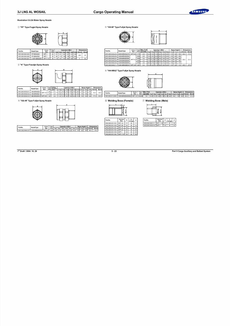
8/12/2019 LNG Cargo Operating Manual
http://slidepdf.com/reader/full/lng-cargo-operating-manual 167/257
3J LNG AL WOSAIL Cargo Operating Manual

8/12/2019 LNG Cargo Operating Manual
http://slidepdf.com/reader/full/lng-cargo-operating-manual 168/257
1 st Draft / 2004. 10. 29 5 - 24 Part 5 Cargo Auxiliary and Ballast System
Blank Page
3J LNG AL WOSAIL Cargo Operating Manual
Illustration 5.6.3a Dry Powder System
C o f f e r d a m
Engine Room
El. Motor RM Cargo Machinery RM
C o f f e r d a m
C o f f e r d a m
C o f f e r d a m
Passage Way
Passage Way
C o f f e r d a m
No.2
Dry Power Unit
No.3 Monitor
Monitor
Dry Power Unit
No.4
Dry Power Unit
HouseCabinet
8 6 5 4 3 2No.1
7 1

8/12/2019 LNG Cargo Operating Manual
http://slidepdf.com/reader/full/lng-cargo-operating-manual 169/257
1 st Draft / 2004. 10. 29 5 - 25 Part 5 Cargo Auxiliary and Ballast System
Dry Power Unit
Monitor
Monitor Monitor
Hose CabinetTotal : 8 Sets
To HoseCabinet
Mater Control Cabinet
Loacl
Cabinet
Check V/V
Fire Control Staion
No.3 (S) Dry Powder Unit
STB'D PORT
Mater Control Cabinet
C.C.R
STB'D PORT
Loacl
Cabinet
No.2 (P) Dry Powder Unit No.1/4 Dry Powder Unit

8/12/2019 LNG Cargo Operating Manual
http://slidepdf.com/reader/full/lng-cargo-operating-manual 170/257
3J LNG AL WOSAIL Cargo Operating Manual
Illustration 5.6.3b Dry Powder System
Cleaning Line
Cleaning Line
Local
PORT
Agitation V/V
MainRegulator Vent Bleed
No. 1Ball V/V
Ball V/V
No. 2Ball V/V
ExhaustLineExhaust
V/V
Non-ReturnCheck V/V
Non-ReturnCheck V/V
Main V/V SelectionV/V
Monitor Nozzle
Safety Relief V/V
ConstantPress. V/V
MicroV/V
Micro V/V Actuator
Instruction ChartCont. Regulator W/Gauge No.3 Control V/V
(Normal Open)1P
2P
CleaningValve
N o . 1
C o n
t r o
l V / V
N o . 2
C o n
t r o
l V / V
Release Control Cabinet
Instruction Chart
Upper InletN2 Gas Line
Lower InletN2 Gas Line
Fire Control Station
Dry Power Unit (PORT)
Cylinder Rack Unit
Cleaning Line
Cleaning Line
Agitation V/V
MainRegulator Vent Bleed
No. 1Ball V/V
No. 2Ball V/V
ExhaustLineExhaust
V/V
Non-ReturnCheck V/V
Manifold
Selection V/V
Main V/V
Safety Relief V/V
ConstantPress. V/V
MicroV/V
Micro V/V Actuator
Instruction ChartCont. Regulator W/Gauge No.3 Control V/V
(Normal Open)
CleaningValve
N o . 1
C o n
t r o
l V / V
N o . 2
C o n
t r o
l V / V
Upper InletN2 Gas Line
Lower InletN2 Gas Line
Cylinder Rack Unit
1P
2P
1P
2P
Instruction ChartC.C.R
To Hand Hose (2)
To Hand Hose (4)
No.2
No.4
No.6
To Hand Hose (6)
Dry Pow er Unit (AFT)
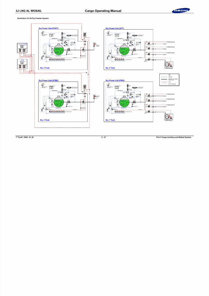
8/12/2019 LNG Cargo Operating Manual
http://slidepdf.com/reader/full/lng-cargo-operating-manual 171/257
1 st Draft / 2004. 10. 29 5 - 27 Part 5 Cargo Auxiliary and Ballast System
Key
Nitrogen
Nitrogen and SodiumBicarbonate
CO2
Electrical Signal
No. 2 Tank
Cleaning Line
Cleaning Line
Local
PORT
Agitation V/V
MainRegulator Vent Bleed
No. 1Ball V/V
Ball V/V
No. 2Ball V/V
ExhaustLineExhaust
V/V
Non-ReturnCheck V/V
Non-ReturnCheck V/V
Main V/V SelectionV/V
Monitor Nozzle
Safety Relief V/V
ConstantPress. V/V
MicroV/V
Micro V/V Actuator
Instruction ChartCont. Regulator W/Gauge No.3 Control V/V
(Normal Open) 1P
2P
CleaningValve
N o . 1
C o n
t r o
l V / V
N o . 2
C o n
t r o
l V / V
Upper InletN2 Gas Line
Lower InletN2 Gas Line
No. 3 Tank
Dry Power Unit (STBD)
Cylinder Rack Unit
Release Control Cabinet
1P
2P
1P
2P
To Hand Hose (8)No. 4 Tank
Cleaning Line
Cleaning Line
Agitation V/V
MainRegulator Vent Bleed
No. 1Ball V/V
No. 2Ball V/V
ExhaustLineExhaust
V/V
Non-ReturnCheck V/V
Manifold
Selection V/V
Main V/V
Safety Relief V/V
ConstantPress. V/V
MicroV/V
Micro V/V Actuator
Instruction ChartCont. Regulator W/Gauge No.3 Control V/V
(Normal Open)
CleaningValve
N o . 1
C o n
t r o
l V / V
N o . 2
C o n
t r o
l V / V
Upper InletN2 Gas Line
Lower InletN2 Gas Line
Cylinder Rack Unit
To Hand Hose (3)
To Hand Hose (5)
No.3
No.4
No.7
To Hand Hose (7)
To Hand Hose (1)No. 1 Tank
Dry Pow er Unit (FW D)
3J LNG AL WOSAIL Cargo Operating Manual

8/12/2019 LNG Cargo Operating Manual
http://slidepdf.com/reader/full/lng-cargo-operating-manual 172/257
1 st Draft / 2004. 10. 29 5 - 28 Part 5 Cargo Auxiliary and Ballast System
Blank Page
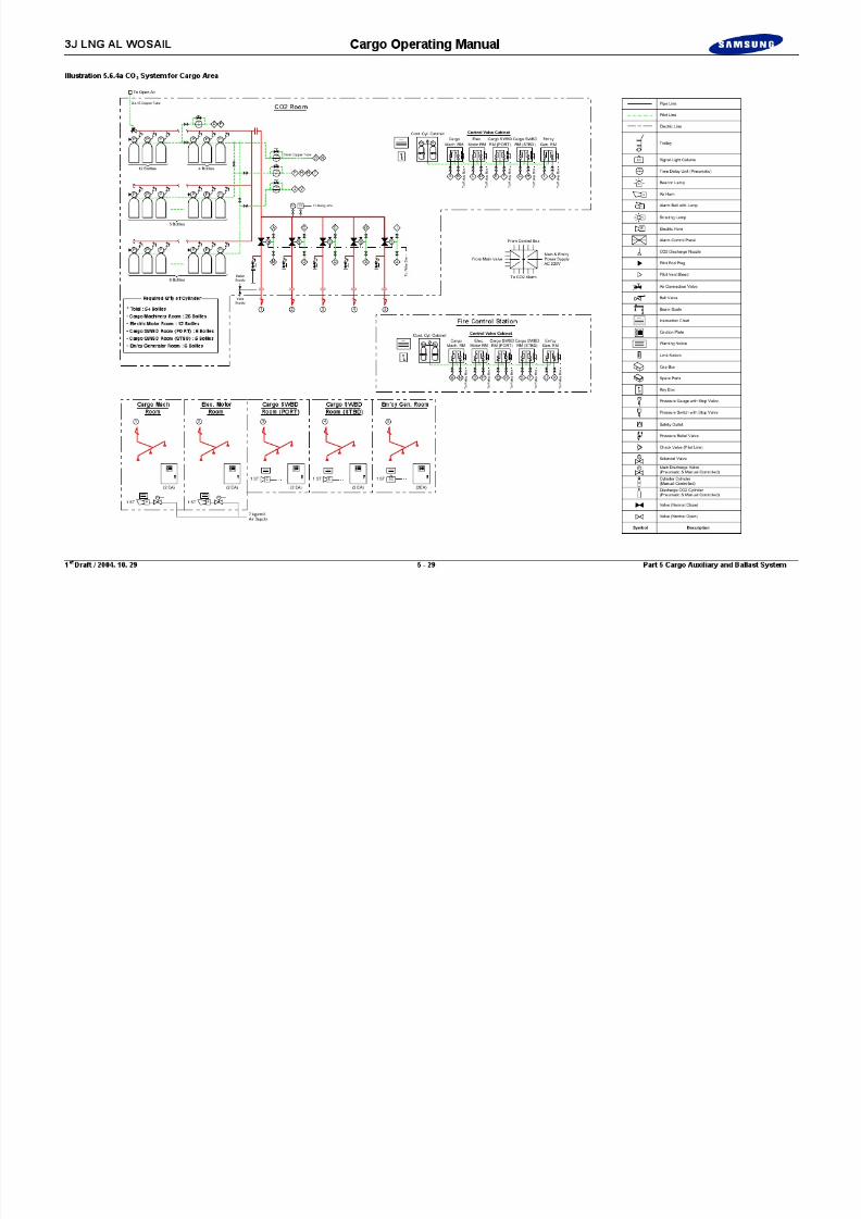
8/12/2019 LNG Cargo Operating Manual
http://slidepdf.com/reader/full/lng-cargo-operating-manual 173/257

8/12/2019 LNG Cargo Operating Manual
http://slidepdf.com/reader/full/lng-cargo-operating-manual 174/257
3J LNG AL WOSAIL Cargo Operating Manual
Illustration 5.6.5a Fire Alarm Panel
SECTION DETECTOR
6 13
Illustration 5.6.5b Control Unit Panel
10:11:23Salwico CS3004 1993-11-13
F1 F4F2 F3
POWER ON ...
DISCONNECTION ...
TEST............
ALARM TRANSFER .
EXTERNAL ALARM .
DELAY OFF ...
SYSTEM FAULT ..

8/12/2019 LNG Cargo Operating Manual
http://slidepdf.com/reader/full/lng-cargo-operating-manual 175/257
1 st Draft / 2004. 10. 29 5 - 31 Part 5 Cargo Auxiliary and Ballast System
ALARM MUTE
EXTERNAL CONTROL ACTIVATED
ALARMS IN QUEUE
ALARM RESET
SECTION / DETECTORNOT RESET
F1
7 8 9
4 5 6
1
S SECTION
DIRECTOR
SMOKEDETECTOR
D
SD
TIMEROFFON LIST
EA
ALARMDELAY
EXTERNALCONTROL
EXTERNAL ALARM
EC
AD
MUTE
FAULT
M
RESETR2
0
3
F4F2 F3 ABNORMAL COND.

8/12/2019 LNG Cargo Operating Manual
http://slidepdf.com/reader/full/lng-cargo-operating-manual 176/257

8/12/2019 LNG Cargo Operating Manual
http://slidepdf.com/reader/full/lng-cargo-operating-manual 177/257

8/12/2019 LNG Cargo Operating Manual
http://slidepdf.com/reader/full/lng-cargo-operating-manual 178/257

8/12/2019 LNG Cargo Operating Manual
http://slidepdf.com/reader/full/lng-cargo-operating-manual 179/257
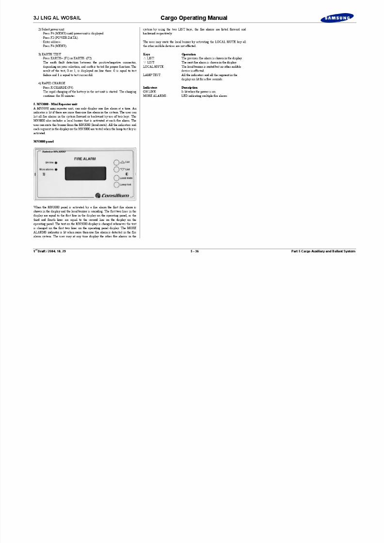
8/12/2019 LNG Cargo Operating Manual
http://slidepdf.com/reader/full/lng-cargo-operating-manual 180/257

8/12/2019 LNG Cargo Operating Manual
http://slidepdf.com/reader/full/lng-cargo-operating-manual 181/257
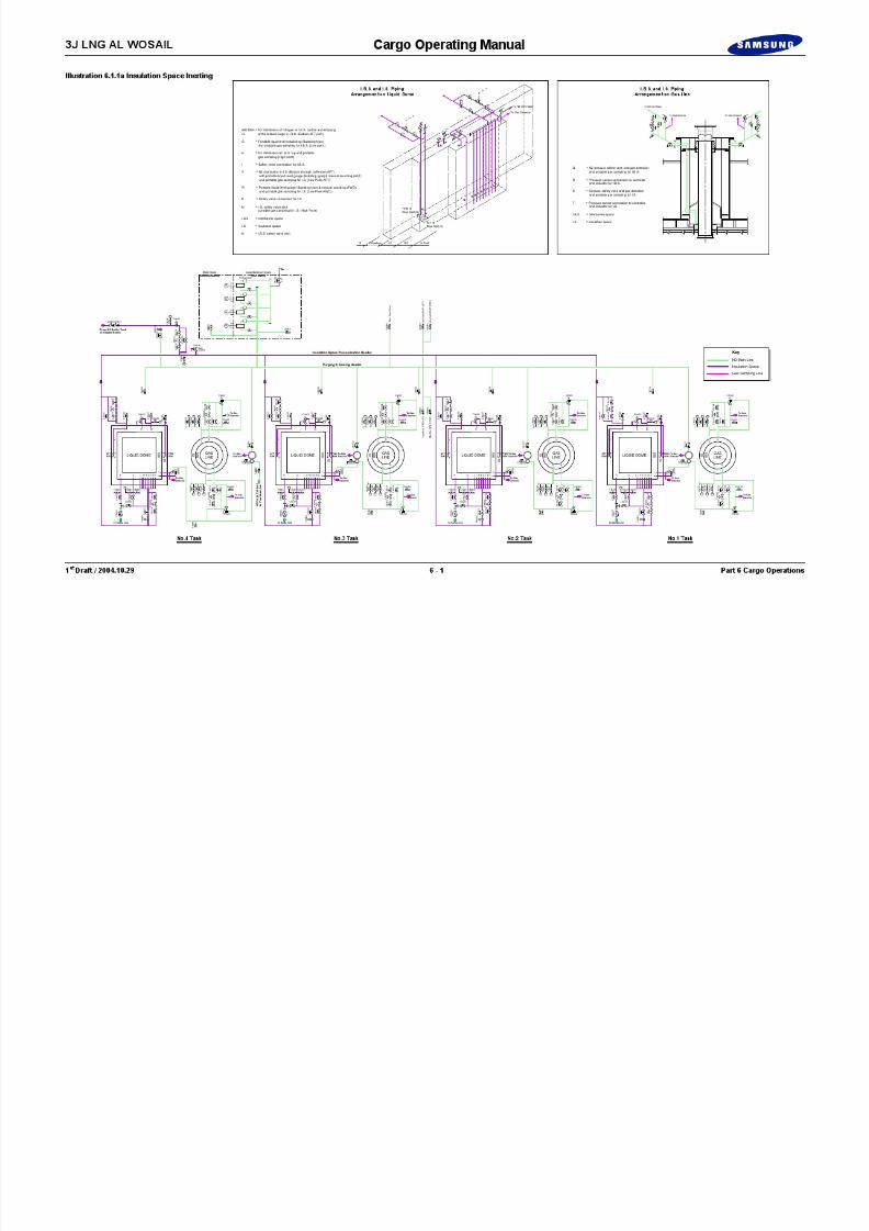
8/12/2019 LNG Cargo Operating Manual
http://slidepdf.com/reader/full/lng-cargo-operating-manual 182/257
8/12/2019 LNG Cargo Operating Manual
http://slidepdf.com/reader/full/lng-cargo-operating-manual 183/257

8/12/2019 LNG Cargo Operating Manual
http://slidepdf.com/reader/full/lng-cargo-operating-manual 184/257

8/12/2019 LNG Cargo Operating Manual
http://slidepdf.com/reader/full/lng-cargo-operating-manual 185/257

8/12/2019 LNG Cargo Operating Manual
http://slidepdf.com/reader/full/lng-cargo-operating-manual 186/257
8/12/2019 LNG Cargo Operating Manual
http://slidepdf.com/reader/full/lng-cargo-operating-manual 187/257
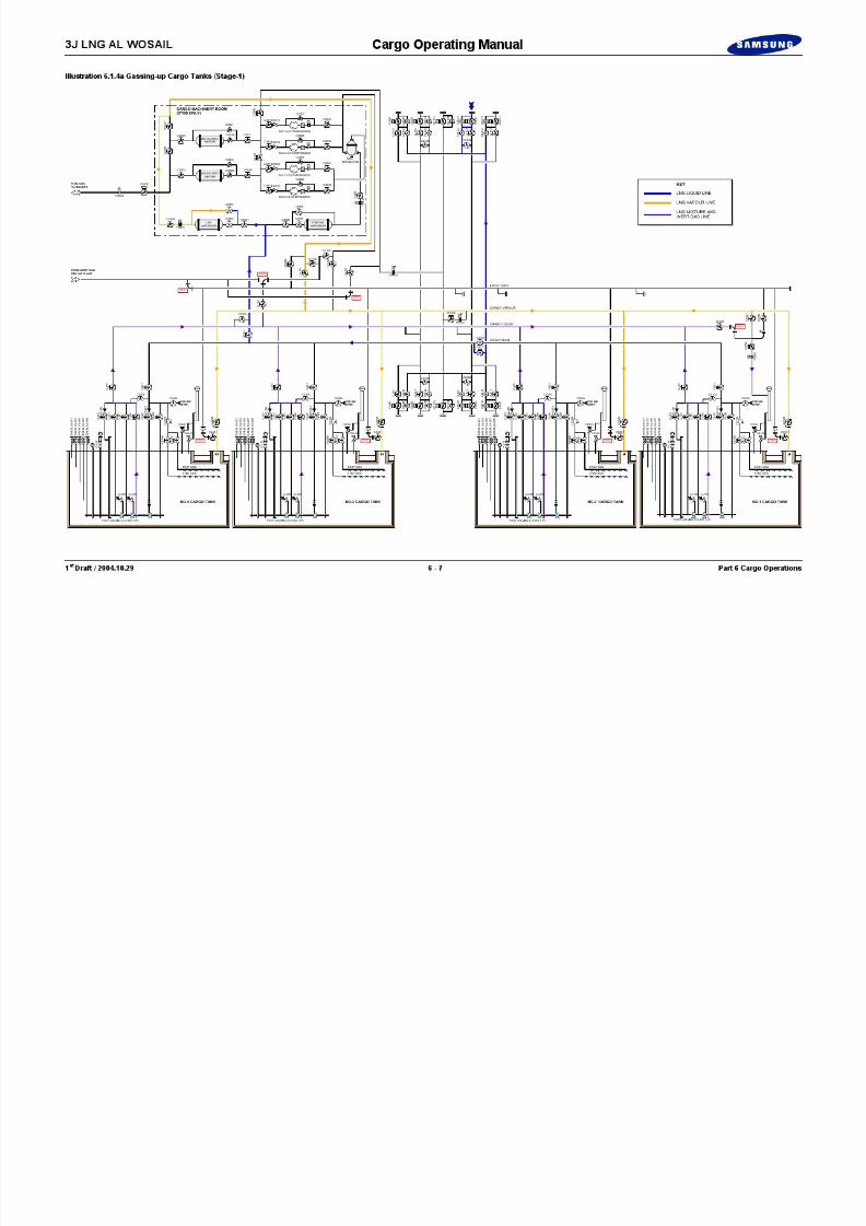
8/12/2019 LNG Cargo Operating Manual
http://slidepdf.com/reader/full/lng-cargo-operating-manual 188/257

8/12/2019 LNG Cargo Operating Manual
http://slidepdf.com/reader/full/lng-cargo-operating-manual 189/257

8/12/2019 LNG Cargo Operating Manual
http://slidepdf.com/reader/full/lng-cargo-operating-manual 190/257

8/12/2019 LNG Cargo Operating Manual
http://slidepdf.com/reader/full/lng-cargo-operating-manual 191/257

8/12/2019 LNG Cargo Operating Manual
http://slidepdf.com/reader/full/lng-cargo-operating-manual 192/257

8/12/2019 LNG Cargo Operating Manual
http://slidepdf.com/reader/full/lng-cargo-operating-manual 193/257

8/12/2019 LNG Cargo Operating Manual
http://slidepdf.com/reader/full/lng-cargo-operating-manual 194/257
3J LNG AL WOSAIL Cargo Operating Manual

8/12/2019 LNG Cargo Operating Manual
http://slidepdf.com/reader/full/lng-cargo-operating-manual 195/257
1 st Draft / 2004.10.29 6 - 14 Part 6 Cargo Operations
Blank Page
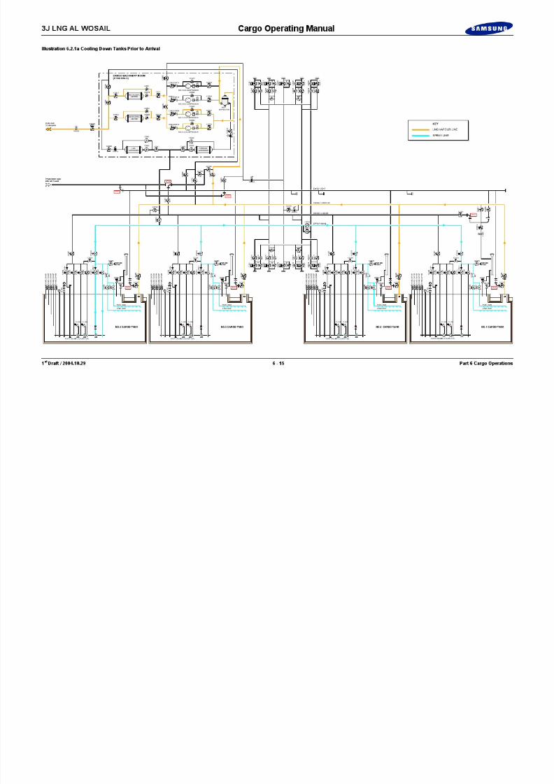
8/12/2019 LNG Cargo Operating Manual
http://slidepdf.com/reader/full/lng-cargo-operating-manual 196/257

8/12/2019 LNG Cargo Operating Manual
http://slidepdf.com/reader/full/lng-cargo-operating-manual 197/257

8/12/2019 LNG Cargo Operating Manual
http://slidepdf.com/reader/full/lng-cargo-operating-manual 198/257

8/12/2019 LNG Cargo Operating Manual
http://slidepdf.com/reader/full/lng-cargo-operating-manual 199/257

8/12/2019 LNG Cargo Operating Manual
http://slidepdf.com/reader/full/lng-cargo-operating-manual 200/257
3J LNG AL WOSAIL Cargo Operating Manual

8/12/2019 LNG Cargo Operating Manual
http://slidepdf.com/reader/full/lng-cargo-operating-manual 201/257
1 st Draft / 2004.10.29 6 - 20 Part 6 Cargo Operations
Blank Page
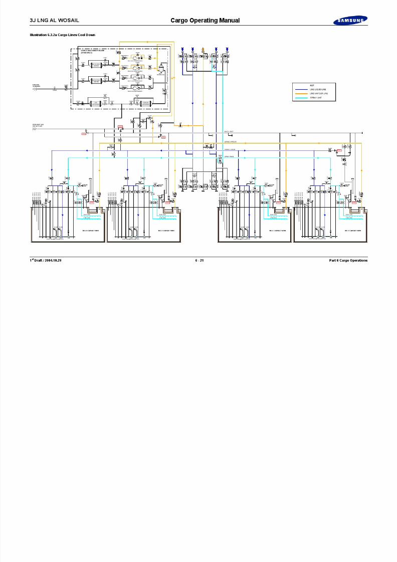
8/12/2019 LNG Cargo Operating Manual
http://slidepdf.com/reader/full/lng-cargo-operating-manual 202/257
3J LNG AL WOSAIL Cargo Operating Manual
6.3.2 Cargo Lines Cool Down(See Illustration 6.3.2a)
Assuming the ship is port side alongside.
1) Open liquid manifold valves CL013, 023, 033, 043 and the LNGmanifold ESD valves CL011, 021, 031 and 041.
2) Open valves on spray header, CS103, 203, 303, 403, 071 and 700.
3) On each vapour dome, open the following valves to allow the supply ofLNG to the spray nozzle: CS107, 108, 207, 208, 307, 308, 407 and 408.
4) Open valves on liquid header for each tank CL107, 207, 307 and 407.
5) Open the vapour manifold valve CG071.
6) Open manifold valve CS023, which will allow liquid into thestripping/spray main via crossover valve CS071, CS700, if necessaryfor additional cooldown in the cargo tanks.
7) Fully open the liquid filling valves CL100, 200, 300 and 400.
8) Inform the terminal that the ship is ready to receive LNG.
The terminal should be instructed to begin pumping at a slow rate for
On each tank keep open the stripping/spray valves to the spray nozzle in order toavoid over-pressure due to line warm up.
11) Start one HD compressor and adjust the flow rate to maintain the tankvapour pressure at 5 kPaG.
8/12/2019 LNG Cargo Operating Manual
http://slidepdf.com/reader/full/lng-cargo-operating-manual 203/257
1 st Draft / 2004.10.29 6 - 22 Part 6 Cargo Operations
The terminal should be instructed to begin pumping at a slow rate forapproximately 15 minutes, in order to gradually cool down the terminal pipingand the ship’s headers.
Slowly increase the terminal pumping rate until the liquid main and sprayheaders have cooled down (approximately 15/20 minutes).
9) Assuming that the after loading arm is the first to be cooled down:Crack open the liquid filling valves CL100 and CL400 for No.1 and 4cargo tanks and Close the CL200 and CL300.
10) Assuming that the liquid header and liquid filling valves CL100,CL400 are cooled down:Crack open the liquid filling valves CL200 and CL300.
NoteIn order to avoid the possibility of pipe sections hogging, the liquid header andcrossovers must be cooled down.
On completion of the loading arm cool down.
11) Fully open the filling valves to the tanks CL100, 200, 300 and 400 forLoading.
12) Close manifold valve CS023.
3J LNG AL WOSAIL Cargo Operating Manual
Cooldown & Loading Sequence
BERTHING
SETTING OF THE SHORE GANGWAY FITTING OIL FENCE & WARNING BUOYS
INSTALLATION OF COMMUNICATION SYSTEM(F/O CABLE),ESD PNEUMATIC HOSE
SHIP/SHORE PRE-LOADING MEETING
START WATER CURTAIN
CONNECTING LOADING ARM
LEAK TEST & O2 PURGING
LINE UP FOR PURGING THE INERT GAS
LIQUID ARM COOL DOWN
TRIP TEST
TRIP TEST
LOADING STARTED
LOADING FINISHED
DRAIN THE LIQUID LOADING ARM
FINAL GAUGING (CLOSING CTMS)
PURGING THE LIQUID LOADING ARM
DISCONNECTING LIQUID LOADING ARM
SAMPLING

8/12/2019 LNG Cargo Operating Manual
http://slidepdf.com/reader/full/lng-cargo-operating-manual 204/257
1 st Draft / 2004.10.29 6 - 23 Part 6 Cargo Operations
INERT GAS PURGING STARTED
INERT GAS PURGING FINISHED
COOL DOWN OF CARGO TANKS STARTED
COOL DOWN OF CARGO TANKS COMPLETED
OPENING CTMS
REMOVAL OF WANING BUOYS
COOL DOWN REMAINING LOADING ARMS
PURGING THE VAPOUR RETURN ARM
DISCONNECTING THE ESD PNEUMATIC HOSE,COMMUNICATION SYSTEM (F/O CABLE)
REMOVING THE SHORE GANGWAY
UNBERTHING
STOP WATER CURTAIN
MEETING AFTER LOADING
DISCONNECTING VAPOUR RETURN ARM
Q
VAPOUR LINE OPENED
COOL DOWN OF LIQUID LINE
3J LNG AL WOSAIL Cargo Operating Manual
LNG Loading Operation Sequence
BERTHING
SETTING OF THE SHORE GANGWAY FITTING OIL FENCE & WARNING BUOYS
INSTALLATION OF COMMUNICATION SYSTEM(F/O CABLE),ESD PNEUMATIC HOSE
SHIP/SHORE PRE-LOADING MEETING
START WATER CURTAIN
CONNECTING LOADING ARM
O2 PURGING WITH N2 & LEAK TEST
INITIAL GAUGING (OPENING CTMS)
DRAINING THE LIQUID LOADING ARM
FINAL GAUGING (CLOSING CTMS)
PURGING THE LIQUID LOADING ARM
DISCONNECTING LIQUID LOADING ARM
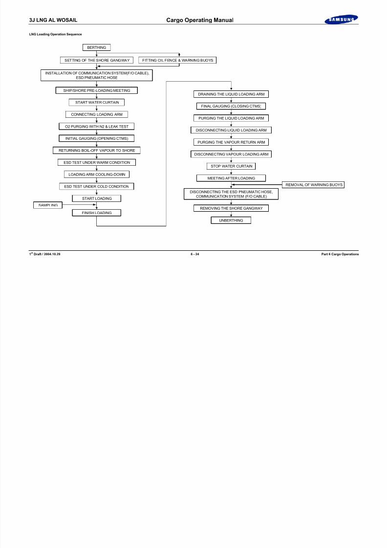
8/12/2019 LNG Cargo Operating Manual
http://slidepdf.com/reader/full/lng-cargo-operating-manual 205/257
1 st Draft / 2004.10.29 6 - 24 Part 6 Cargo Operations
INITIAL GAUGING (OPENING CTMS)
RETURNING BOIL-OFF VAPOUR TO SHORE
ESD TEST UNDER WARM CONDITION
LOADING ARM COOLING-DOWN
ESD TEST UNDER COLD CONDITION
START LOADING
FINISH LOADING
SAMPLING
REMOVAL OF WARNING BUOYS
PURGING THE VAPOUR RETURN ARM
DISCONNECTING VAPOUR LOADING ARM
STOP WATER CURTAIN
MEETING AFTER LOADING
DISCONNECTING THE ESD PNEUMATIC HOSE,COMMUNICATION SYSTEM (F/O CABLE)
REMOVING THE SHORE GANGWAY
UNBERTHING

8/12/2019 LNG Cargo Operating Manual
http://slidepdf.com/reader/full/lng-cargo-operating-manual 206/257

8/12/2019 LNG Cargo Operating Manual
http://slidepdf.com/reader/full/lng-cargo-operating-manual 207/257
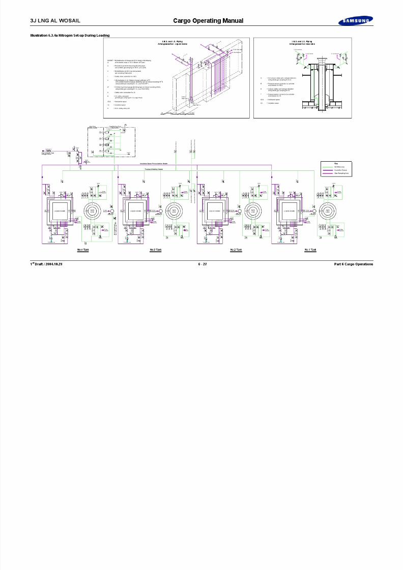
8/12/2019 LNG Cargo Operating Manual
http://slidepdf.com/reader/full/lng-cargo-operating-manual 208/257
3J LNG AL WOSAIL Cargo Operating Manual
6.3.4 Nitrogen Set-up during Loading(See Illustration 6.3.4a)
The operating procedure for normal inerting is as follows.
1) Start one nitrogen generator to pressurise the buffer tank. The pressuredrop in the buffer tank actuates the starting of the generator. In the caseof a large nitrogen demand, the stand-by generator will automaticallystart.
2) Adjust the setpoint of the nitrogen supply pressure control valves; inter barrier space 0.5 ~ 1 kPaG and insulation space, 1 ~ 1.5 kPaG.
3) Adjust the set point of the nitrogen exhaust pressure control valves;inter barrier space, 1 ~ 1.5 kPaG and insulation space, 1.5 ~ 2.0 kPaG.
In cases where other consumers reduce the availability of nitrogen for theinsulation spaces, the pressure may temporarily fall below the atmospheric
pressure.
When put in communication and therefore subjected to the same nitrogen pressure, the primary and secondary insulation spaces can withstand a largedepressurisation without any damage.
It should be noted that, even with the tanks fully loaded, a pressure lower thanatmospheric pressure in the primary insulation spaces is not harmful to the
primary membrane.

8/12/2019 LNG Cargo Operating Manual
http://slidepdf.com/reader/full/lng-cargo-operating-manual 209/257
1 st Draft / 2004.10.29 6 - 28 Part 6 Cargo Operations
In this respect, it should be recalled that this membrane is subjected to a -800kPa vacuum pressure both during global testing at the construction stage.
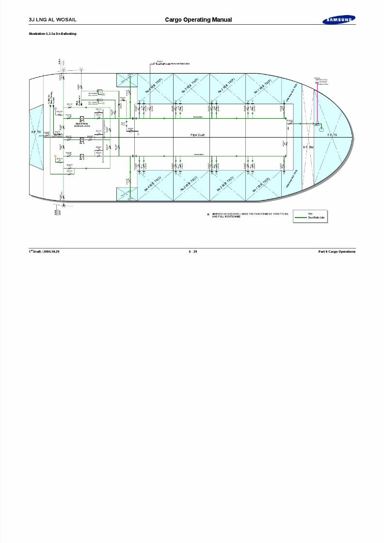
8/12/2019 LNG Cargo Operating Manual
http://slidepdf.com/reader/full/lng-cargo-operating-manual 210/257

8/12/2019 LNG Cargo Operating Manual
http://slidepdf.com/reader/full/lng-cargo-operating-manual 211/257
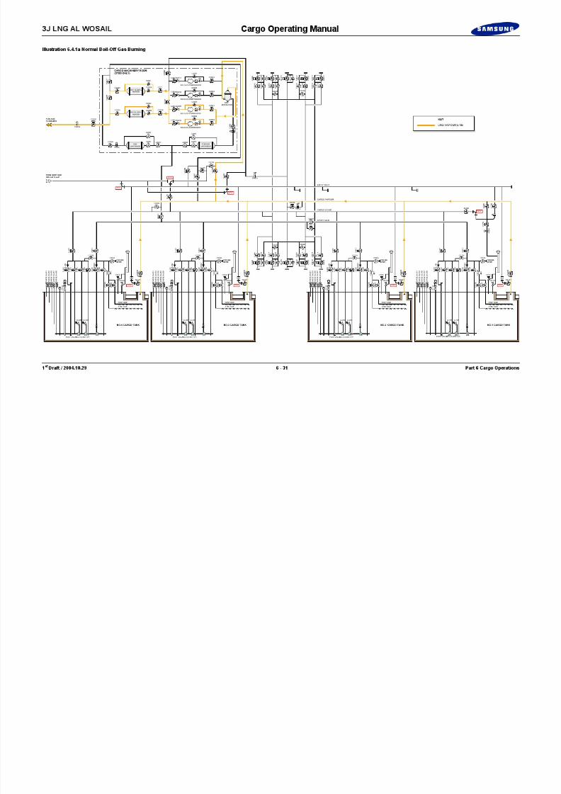
8/12/2019 LNG Cargo Operating Manual
http://slidepdf.com/reader/full/lng-cargo-operating-manual 212/257

8/12/2019 LNG Cargo Operating Manual
http://slidepdf.com/reader/full/lng-cargo-operating-manual 213/257

8/12/2019 LNG Cargo Operating Manual
http://slidepdf.com/reader/full/lng-cargo-operating-manual 214/257

8/12/2019 LNG Cargo Operating Manual
http://slidepdf.com/reader/full/lng-cargo-operating-manual 215/257
3J LNG AL WOSAIL Cargo Operating Manual
Illustration 6.5.1a Inerting Manifold Connections
Vapour Header
LiquidHeader
Forward
Port Starboard
Stripping/SprayHeader
CS032CS034
CL012
CS012CS014
CL014
CL054
CL053 C L 0 5 7
C L 0 5 8
ESD
CL011
CS011 CS013
CL013
CL052
CL051 C L 0 5 6
C L 0 5 5
ESD
CS031 CS033
76 75
CG073
CG071ESD
CL021
CS021 CS023
CL023 C S 0 2 5
C S 7 0 0
C S 7 0 1
ESD
CG052CG051
CS051
CS052CS053
CS054
CR053
CR054
CR051
CR052
77 78
CL022
CS022CS024
CL024
CL064
CL063 C L 0 6 7
C L 0 6 8
C S 0 2 6
ESD
CL062
CL061 C L 0 6 6
C L 0 6 5
CG055CG056
CG074
CG072ESD
CG054CG053
CG057CG058
C G 0 7 5
F M 0 0 2
O F
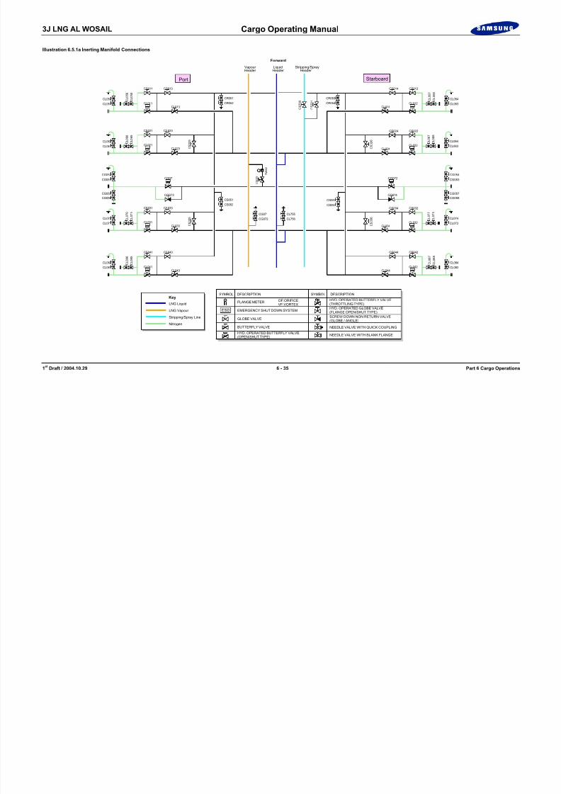
8/12/2019 LNG Cargo Operating Manual
http://slidepdf.com/reader/full/lng-cargo-operating-manual 216/257
1 st Draft / 2004.10.29 6 - 35 Part 6 Cargo Operations
CL041
CS041 CS043
CL043
CL082
CL081 C L 0 8 6
C L 0 8 5
Key
LNG Liquid
LNG Vapour
Nitrogen
Stripping/Spray Line
ESD
CL042
CS042CS044
CL032
CL044
CL034
CL084
CL083 C L 0 8 7
C L 0 8 8
ESD
CL031CL033
CL072
CL071 C L 0 7 6
C L 0 7 5
C S 0 3 5
ESD
CG071
CG072
CL755
CL756 CL074
CL073 C L 0 7 7
C L 0 7 8
C S 0 3 6
ESD
OF
FLANGE METER OF:ORIFICEVF:VORTEX
EMERGENCY SHUT DOWN SYSTEM
SYMBOL SYMBOLDESCRIPTION DESCRIPTION
GLOBE VALVE
HYD. OPERATED BUTTERFLY VALVE(OPEN/SHUT TYPE)
HYD. OPERATED BUTTERFLY VALVE(THROTTLING TYPE)HYD. OPERATED GLOBE VALVE
(FLANGE OPEN/SHUT TYPE)
BUTTERFLY VALVE NEEDLE VALVE WITH QUICK COUPLING
NEEDLE VALVE WITH BLANK FLANGE
SCREW DOWN NON RETURN VALVE(GLOBE / ANGLE)
ESD

8/12/2019 LNG Cargo Operating Manual
http://slidepdf.com/reader/full/lng-cargo-operating-manual 217/257

8/12/2019 LNG Cargo Operating Manual
http://slidepdf.com/reader/full/lng-cargo-operating-manual 218/257
3J LNG AL WOSAIL Cargo Operating Manual
6.5.2 Liquid Line and Arm Cooldown before Discharging(See Illustration 6.5.2a)
To cooldown the cargo discharge lines proceed as follows, assuming that No.3stripping/spray pump is being used, all manifold lines and the ESD valves areopen and have been purged with nitrogen.
1) Open discharge valve CS301 from No.3 stripping/spray pump to 30 %.
2) Open the following valves CS013, 023, 033, 043 and 071.
3) Open No.3 tank return valve CS300.
4) Start the No.3 stripping/spray pump.
5) Close slowly return valve CS300 and increase the flow rate of No.3stripping/spray pump.
6) Open liquid header valves for each tank CL107, 207, 307, and 407.
7) When hard-arms and shore side lines have cooled down to -100 °C,open valves CS025, 035 and crack open No.1 & 4 liquid filling valvesCL100 and 400. This will now cool down the ship’s liquid line.
The cooling down is complete when the shore side line and ship’s liquid line isapproximately -130 °C.
5) Stop the No.3 stripping/spray pump and close discharge valve CS301.Shut valves CS025, 035, 013, 023, 033 and 043.
LNG Unloading Operation Sequence
BERTHING
SETTING OF THE SHORE GANGWAY FITTING OIL FENCE & WARNING BUOYS
INSTALLATION OF COMMUNICATION SYSTEM(F/O CABLE),ESD PNEUMATIC HOSE
SHIP/SHORE PRE-UNLOADING MEETING
START WATER CURTAIN
CONNECTING LOADING ARM
O2 PURGING WITH N2 & LEAK TEST
INITIAL GAUGING (OPENING CTMS)
RETURNING BOIL-OFF VAPOUR TO SHORE
ESD TEST UNDER WARM CONDITION
LOADING ARM COOLING-DOWN
ESD TEST UNDER COLD CONDITION REMOVAL OF WARNING BUOYS
DRAINING THE LIQUID LOADING ARM
FINAL GAUGING (CLOSING CTMS)
PURGING THE LIQUID LOADING ARM
DISCONNECTING LIQUID LOADING ARM
PURGING THE VAPOUR RETURN ARM
DISCONNECTING VAPOUR LOADING ARM
STOP WATER CURTAIN
MEETING AFTER UNLOADING

8/12/2019 LNG Cargo Operating Manual
http://slidepdf.com/reader/full/lng-cargo-operating-manual 219/257
1 st Draft / 2004.10.29 6 - 38 Part 6 Cargo Operations
, , , ,Open valve CS300 to drain the line back to No.3 cargo tank.
6) When the spray line has warmed up, close valves CS071 and 300.
On completion of cooldown and when shore is ready for discharge, proceed withunloading.
START UNLOADING
FINISH UNLOADING
SAMPLING
DISCONNECTING THE ESD PNEUMATIC HOSE,COMMUNICATION SYSTEM (F/O CABLE)
REMOVING THE SHORE GANGWAY
UNBERTHING
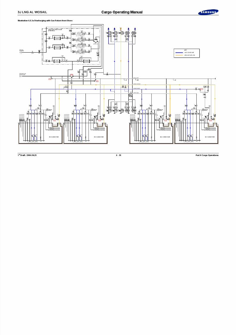
8/12/2019 LNG Cargo Operating Manual
http://slidepdf.com/reader/full/lng-cargo-operating-manual 220/257

8/12/2019 LNG Cargo Operating Manual
http://slidepdf.com/reader/full/lng-cargo-operating-manual 221/257

8/12/2019 LNG Cargo Operating Manual
http://slidepdf.com/reader/full/lng-cargo-operating-manual 222/257
3J LNG AL WOSAIL Cargo Operating Manual
Blank Page

8/12/2019 LNG Cargo Operating Manual
http://slidepdf.com/reader/full/lng-cargo-operating-manual 223/257
1 st Draft / 2004.10.29 6 - 42 Part 6 Cargo Operations

8/12/2019 LNG Cargo Operating Manual
http://slidepdf.com/reader/full/lng-cargo-operating-manual 224/257

8/12/2019 LNG Cargo Operating Manual
http://slidepdf.com/reader/full/lng-cargo-operating-manual 225/257
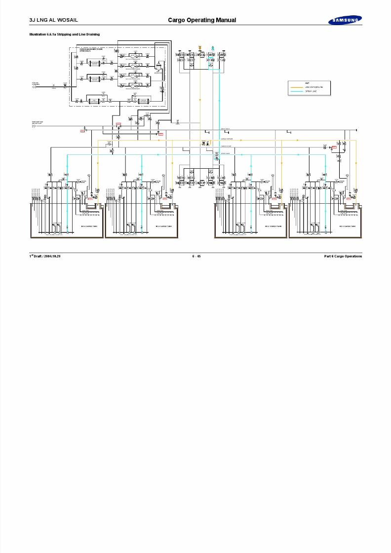
8/12/2019 LNG Cargo Operating Manual
http://slidepdf.com/reader/full/lng-cargo-operating-manual 226/257

8/12/2019 LNG Cargo Operating Manual
http://slidepdf.com/reader/full/lng-cargo-operating-manual 227/257

8/12/2019 LNG Cargo Operating Manual
http://slidepdf.com/reader/full/lng-cargo-operating-manual 228/257

8/12/2019 LNG Cargo Operating Manual
http://slidepdf.com/reader/full/lng-cargo-operating-manual 229/257

8/12/2019 LNG Cargo Operating Manual
http://slidepdf.com/reader/full/lng-cargo-operating-manual 230/257

8/12/2019 LNG Cargo Operating Manual
http://slidepdf.com/reader/full/lng-cargo-operating-manual 231/257
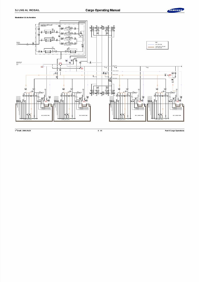
8/12/2019 LNG Cargo Operating Manual
http://slidepdf.com/reader/full/lng-cargo-operating-manual 232/257
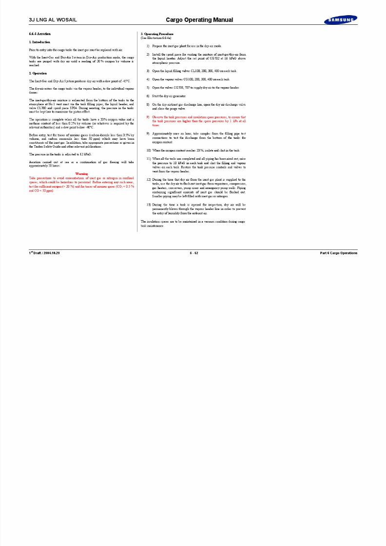
8/12/2019 LNG Cargo Operating Manual
http://slidepdf.com/reader/full/lng-cargo-operating-manual 233/257
3J LNG AL WOSAIL Cargo Operating Manual
Illustration 6.6.5a Cofferdam Space Aeration
C o f f e r d a m
El. Motor RM Cargo Machinery RM
C o f f e r d a m
C o f f e r d a m
C o f f e r d a m
Passage Way
Passage Way
C o f f e r d a m
Cargo Manifold (S)
Cargo Manifold (P)
Dry Air SupplyFrom IGG Systemin Engine Room
To CargoVapour Line
Em'cy Vent Line
Flex. Hose Conn. for Dry Air SupplyTo Cofferdam (P-only)Conn. for portable Fan (P-only)
G I 7 0 3
SpoolPiece
Flex. Hose Conn. for
Dry Air SupplyTo Passage Way (AFT-P&S)
Flex. Hose Conn. for Dry Air SupplyTo Passage-way (FWD-P&S)
Pipe Duct
Nat. Supp. Vent
Passage WayNat. Supp. Vent
Passage WayNat. Supp. Vent
Passage WayNat. Supp. Vent
Passage WayNat. Supp. Vent
Passage WayMech. Exh. Fan
Passage WayMech. Exh. Fan
H
HM/H
H
M/H M/H
To be installing portable
fan on manhole for trunk space(AFT side - P&S)
To be Installing Portable fan on injured person'sManhole for Cofferdam (STBD only)
Manhole cover for Cofferdamto be opened when gas freeing. ({ & S)
M/HM/H M/H
M/H
M/H
M/H
M/H M/H
Manhole cover for trunkto be opened when gasfreeing (FWD side - P & S)
M/H M/H
M/H
M/H
M/H
M/H M/H
M/H M/H
M/H
M/H
M/H
M/H
M/H
M/H
M/H
M/H
Passage WayMech. Exh. Fan
Portable gas freeing fanon dry air pipe for cofferdam (PORT)
Portable gas freeing fanon manhole for trunk (AFT - P&S)
Portable gas freeing fanon Manhole for C/DManhole cover for C/D to be
opened when gas freeing (P&S)
Manhole cover for trun to be openedwhen gas freeing(FWD - P&S)

8/12/2019 LNG Cargo Operating Manual
http://slidepdf.com/reader/full/lng-cargo-operating-manual 234/257
1 st Draft / 2004.10.29 6 - 53 Part 6 Cargo Operations
Typical Section for Gas Freeing & Dry Air Supply
(Trans. C/D, Trunk Spade)
3J LNG AL WOSAIL Cargo Operating Manual
6.6 .5 Aeration of Cofferdam Space
1. Introduction
Prior to entry into the cofferdam spaces the hazardous gas must be replaced withair.
With the Inert Gas and Dry-Air System in Dry-Air production mode, the cargotanks are purged with dry air until a reading of 20 % oxygen by volume isreached.
2. Operation
The Inert Gas and Dry-Air System produces dry air with a dew point of -45°C.
The dry-air enter the bottom of cofferdam spaces via the dry air pipe forcofferdam on the port side of trunk.
The hazardous gas is exhausted from the manhole of the cofferdam.
The operation is complete when all the tanks have a 20 % oxygen value.
Before entry, test for traces of noxious gases (carbon dioxide less than 0.5% byvolume, and carbon monoxide less than 50 ppm) which may have beenconstituents of the inert gas. In addition, take appropriate precautions as given inthe Tanker Safety Guide and other relevant publications.
Aeration carried out at sea as a continuation of gas freeing will takeapproximately 2 hours.
WarningTake precautions to avoid concentrations of inert gas or nitrogen in confinedspaces which could be hazardous to personnel Before entering any such areas

8/12/2019 LNG Cargo Operating Manual
http://slidepdf.com/reader/full/lng-cargo-operating-manual 235/257
1 st Draft / 2004.10.29 6 - 54 Part 6 Cargo Operations
spaces, which could be hazardous to personnel. Before entering any such areas,test for sufficient oxygen (> 20 %) and for traces of noxious gases (CO 2 < 0.5 %and CO < 50 ppm).
3. Operating Procedure(See Illustration 6.6.5a)
1) Prepare the inert gas plant for use in the dry-air mode.
2) Install the flexible hoses for dry air supply to cofferdam spaces.
3) Open the manhole cover (P & S) for each cofferdam.
4) Start the dry air generator.
5) On the IAS, open the dry air discharge valve and close the purge valve.
6) When the oxygen content above 20 %, complete aeration.
3J LNG AL WOSAIL Cargo Operating Manual
Part 7 : Emergency Procedures 7.1 Water Leakage to Barrier Space............. ............ ............ ............ ........ 7 - 27.2 Fire and Emergency Breakaway ........... ............ ........... ............ .......... 7 - 37.3 Emergency Cargo Pump Installation ........... ............ ............ ............ .. 7 - 67.4 One Tank Operation...........................................................................7 - 8
7.4.1 Warm Up (No.3 Cargo Tank) ........... ............ ........... ............ .... 7 - 87.4.2 Inerting (No.3 Cargo Tank).......... ............ ........... ............ ...... 7 - 107.4.3 Aeration (No.3 Cargo Tank)....... ............ ........... ............ ........ 7 - 127.4.4 Drying and Inerting (No.3 Cargo Tank)....... ............ ........... .. 7 - 147.4.5 Gassing-up (No.3 Cargo Tank).. ............ ........... ............ ........ 7 - 16
7.4.6 Cool Down (No.3 Cargo Tank).......... ............ ........... ............ 7 - 187.5 Ship to Ship Transfer ........... ............ ............ ............ ............ ............ 7 - 197.6 Jettisoning of Cargo.........................................................................7 - 21

8/12/2019 LNG Cargo Operating Manual
http://slidepdf.com/reader/full/lng-cargo-operating-manual 236/257
1 st Draft / 2004.10.29 Part 7 Emergency Procedures
Part 7Emergency Procedures

8/12/2019 LNG Cargo Operating Manual
http://slidepdf.com/reader/full/lng-cargo-operating-manual 237/257

8/12/2019 LNG Cargo Operating Manual
http://slidepdf.com/reader/full/lng-cargo-operating-manual 238/257
3J LNG AL WOSAIL Cargo Operating Manual
7.2 Fire and Emergency Breakaway
All terminals have their own requirements regarding when it is unsafe for avessel to remain alongside a terminal. These are normally outlined in theterminal handbook.
In case of a Fire or Emergency developing, either on board or ashore, thefollowing basic procedures will be followed:
1) All cargo operations to be stopped and Emergency Signals sounded as per the terminal requirements (as detailed in the ship/shore checklist).
2) Ship and Shore Emergency procedures to be put into operation.
3) The ESD system to be activated, resulting in cargo arms beingdisconnected by the Perc system.
4) In the event of fire, the IMO water spray system on ship/shore is to beactivated.
5) Fire parties to attempt to deal with the situation.
6) Vessel to prepare for departure from the berth.
7) Liaison with shore personnel to arrange for pilot and tugs and additionalsupport.
8) Standby tug requested to assist with fire fighting/movement of thevessel from the berth.
9) Vessel to either move away from the berth to a safe area under its ownpower with assistance of a standby tug, or with additional tugs/pilot

8/12/2019 LNG Cargo Operating Manual
http://slidepdf.com/reader/full/lng-cargo-operating-manual 239/257
1 st Draft / 2004.10.29 7 - 3 Part 7 Emergency Procedures
power with assistance of a standby tug, or with additional tugs/pilotsummoned from shore.
10) The Owners/Charterers and other interested parties to be informed ofthe situation.
3J LNG AL WOSAIL Cargo Operating Manual
Blank Page

8/12/2019 LNG Cargo Operating Manual
http://slidepdf.com/reader/full/lng-cargo-operating-manual 240/257
1 st Draft / 2004.10.29 7 - 4 Part 7 Emergency Procedures
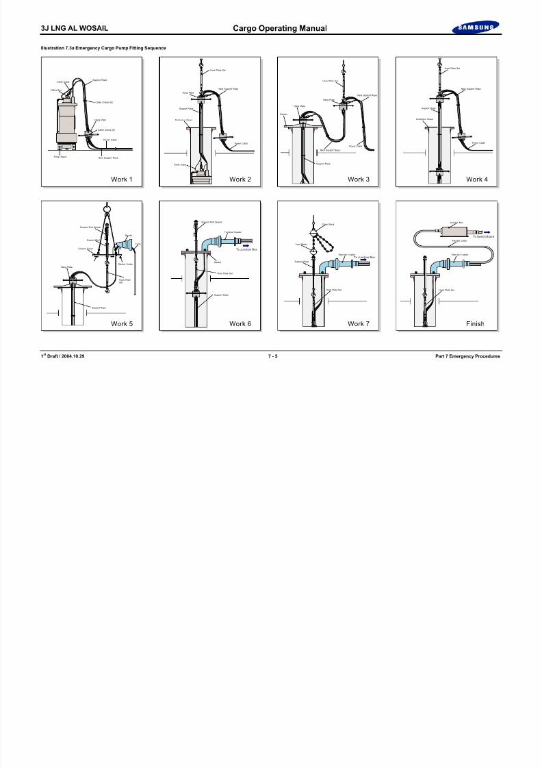
8/12/2019 LNG Cargo Operating Manual
http://slidepdf.com/reader/full/lng-cargo-operating-manual 241/257
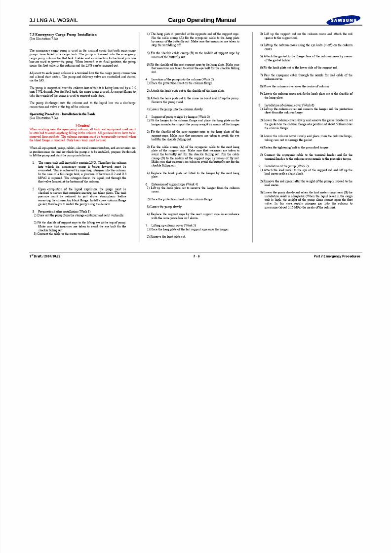
8/12/2019 LNG Cargo Operating Manual
http://slidepdf.com/reader/full/lng-cargo-operating-manual 242/257

8/12/2019 LNG Cargo Operating Manual
http://slidepdf.com/reader/full/lng-cargo-operating-manual 243/257

8/12/2019 LNG Cargo Operating Manual
http://slidepdf.com/reader/full/lng-cargo-operating-manual 244/257

8/12/2019 LNG Cargo Operating Manual
http://slidepdf.com/reader/full/lng-cargo-operating-manual 245/257

8/12/2019 LNG Cargo Operating Manual
http://slidepdf.com/reader/full/lng-cargo-operating-manual 246/257

8/12/2019 LNG Cargo Operating Manual
http://slidepdf.com/reader/full/lng-cargo-operating-manual 247/257
3J LNG AL WOSAIL Cargo Operating Manual
7.4.3 Aeration (No.3 Cargo Tank)(See Illustration 7.4.3a)
Normal gas burning is continued during this operation using vapour from thethree in-service tanks.
Dry air is supplied to the tank by the dry air generator (IGG) via the flap springcheck valve connecting the IG line with the gas header and the fitting of a spool
piece connecting the vapour outlet from the tank to the gas header (shouldalready be in place from the inerting operation). Venting the tank is carried outvia the liquid filling valve, exhausting onto the liquid header and leading to No.1
vent mast via valve CL700 and the spool piece. The isolation valve onto thevapour header (CG300) must remain closed.
1) Fit the spool piece SP04 between liquid header and No.1 vent mast.
2) Fit the spool piece SP05 between No.3 tank vapour line and gas header.
3) Fit the spool piece SP01 between IGG discharge line and gas header
4) Ensure that valve CG300 is securely closed.
5) Open valves CL700 and CG301.
5) Open valves CL307 and CL300.
6) Set the vent mast regulating valve CG702 to 12 kPaG.
7) Start the IGG (One blower, 14,000 Nm 3/h, to be operated).
8) The pressure in the tanks must be kept 10~12 kPaG to maximize the piston effect.
Monitor the change in atmosphere until all levels as described in section 6 7 4
8/12/2019 LNG Cargo Operating Manual
http://slidepdf.com/reader/full/lng-cargo-operating-manual 248/257
1 st Draft / 2004.10.29 7 - 12 Part 7 Emergency Procedures
Monitor the change in atmosphere until all levels as described in section 6.7.4
are obtained.
Ensure pressure in aerated tank is higher than tanks containing vapour to avoidleakage of toxic gas to this tank.
Aerate the emergency cargo pump well with dry air if necessary.

8/12/2019 LNG Cargo Operating Manual
http://slidepdf.com/reader/full/lng-cargo-operating-manual 249/257

8/12/2019 LNG Cargo Operating Manual
http://slidepdf.com/reader/full/lng-cargo-operating-manual 250/257

8/12/2019 LNG Cargo Operating Manual
http://slidepdf.com/reader/full/lng-cargo-operating-manual 251/257
8/12/2019 LNG Cargo Operating Manual
http://slidepdf.com/reader/full/lng-cargo-operating-manual 252/257

8/12/2019 LNG Cargo Operating Manual
http://slidepdf.com/reader/full/lng-cargo-operating-manual 253/257
3J LNG AL WOSAIL Cargo Operating Manual
7.4.6 Cool Down (No.3 Cargo Tank)(See Illustration 7.4.6a)
Assuming a single tank is to be cooled down using the heel in another tank.
It is assumed that all valves are closed prior to use, and it is No.4 tank thatcontains the heel.
Set the No.1 vent mast riser set point to 15 kPaG and the LD compressor(s) online to supply the engine room with boil-off gas for the boilers.
Check the nitrogen system for high flow operation.
Set the supply valve CN511 (nitrogen to the insulation space header) at 500kPaG.
Confirm the set point of the inter barrier space nitrogen supply regulating valvesat 1 kPaG and the insulation space at 1.5 kPaG
Confirm the set point of the inter barrier space nitrogen exhaust regulating valvesat 1.5 kPaG and the insulation space at 1.5 kPaG
1) Open the vapour dome outlet valves to the vapour header CG100, 200,300 and 400.
2) Open the spray inlet valves to the No.3 tank CS307, 308 and 303.
3) Open No.4 stripping/spray pump discharge valve CS401 to 30%, fullyopen return valve CS400 and Start the No.4 stripping/spray pump.
4) Adjust the spray discharge valve CS401 to allow minimum flow andfully open CS403 to cool down No.3 spray header. Pressure in thestripping/spray header shall be controlled by CS400.
5) Once cool down of the spray header to No.3 tank is complete, increasethe flow rate by adjusting No.4 stripping/spray pump discharge valve to

8/12/2019 LNG Cargo Operating Manual
http://slidepdf.com/reader/full/lng-cargo-operating-manual 254/257
1 st Draft / 2004.10.29 7 - 18 Part 7 Emergency Procedures
allow an even cool down and control of vapour pressure.
Care should be taken to control the vapour pressure either in the boilers as fuel,or venting to the atmosphere via CG701, CG702 and the No.1 vent mast riser.
5) On completion of cool down leave the spray header valves open toallow the spray line to warm up to ambient temperature before closingthem.

8/12/2019 LNG Cargo Operating Manual
http://slidepdf.com/reader/full/lng-cargo-operating-manual 255/257
3J LNG AL WOSAIL Cargo Operating Manual
4. Transfer Operations
Transfer can begin when the two Masters have ensured that all the pre-transferchecks and precautions have been completed and agreed between them. Bothships should be prepared to disconnect and un-moor at short notice shouldanything go wrong.
During transfer, ballast operations should be performed in order to keep the trimand list of both vessels constant. Listing of either vessel should be avoidedexcept for proper tank draining. Checks should also be kept on the weather,traffic in the area, and that all safety equipment is still in a state of readiness.
Transfer can take place whilst the two vessels are at anchor. This is the mostcommon method. Transfer can also take place whilst the two vessels areunderway, though this depends on there being adequate sea room, trafficconditions and the availability of large diameter, high absorption fenders.
1) Underway TransferAfter completion of mooring, the constant heading ship maintainssteerage way and the manoeuvring ship adjusts its engine speed andrudder angle to minimise the towing load on the moorings. The courseand speed should be agreed by the two Masters and this should result inthe minimum movement between the two ships. The Master of the
constant heading ship is responsible for the navigation and safety of thetwo vessels.
2) Drifting TransferThis should only be attempted in ideal conditions.
3) Completion of TransferAfter transfer has been completed and before unmooring, all hosesshould be purged, manifolds securely blanked and the relevantauthorities informed that transfer is complete.
5. Unmooring

8/12/2019 LNG Cargo Operating Manual
http://slidepdf.com/reader/full/lng-cargo-operating-manual 256/257
1 st Draft / 2004.10.29 7 - 20 Part 7 Emergency Procedures
This procedure will be carried out, under normal conditions, at anchor, though if both Masters agree, unmooring can take place underway.
Before unmooring begins, obstructions from the adjacent sides of both shipsshould be cleared and the sequence and timing of the event be agreed by bothships, and commenced at the request of the manoeuvring ship. Lines should besingled up fore and aft, then let go the remaining forward mooring allowing theships to drift away from each other, at which time the remaining after mooringsare let go and the ships drift clear of each other. Neither ship should, at this point,attempt to steam ahead or astern until their mid lengths are about two cablesapart.
3J LNG AL WOSAIL Cargo Operating Manual
7.6 Jettisoning of Cargo
WarningThe jettisoning of cargo is an emergency operation. It should only be carried outto avoid serious damage to the cargo tank and/or inner hull steel structure.
A membrane or insulation failure in one or more cargo tanks may necessitate the jettisoning of cargo from that particular cargo tank to the sea. This is carried outusing a single main cargo pump, discharging LNG through a portable nozzlefitted at the ship’s manifold.
As jettisoning of LNG will create hazardous conditions:
1) All the circumstances of the failure must be carefully evaluated beforethe decision to jettison cargo is taken.
2) All relevant fire fighting equipment must be manned, in a state ofreadiness and maintained so during the entire operation.
3) All accommodation and other openings and all vent fans must besecured.
4) The NO SMOKING rule must be rigidly enforced.
5) The water curtain on the side of the jettison is to be running to protectthe ship’s structure.
Weather conditions, and the heading of the vessel relative to the wind, must beconsidered so that the jettisoned liquid and resultant vapour cloud will be carriedaway from the vessel. In addition, if possible, avoid blanketing the vapour withexhaust gases from the funnel.
The discharge rate must be limited to the capacity of one cargo pump only and, ifnecessary, reduced to allow acceptable dispersal within the limits of the
ili th diti
8/12/2019 LNG Cargo Operating Manual
http://slidepdf.com/reader/full/lng-cargo-operating-manual 257/257
1 st Draft / 2004.10.29 7 - 21 Part 7 Emergency Procedures
prevailing weather conditions.


![FREEPORT LNG TERMINALFREEPORT LNG TERMINAL FACILITY MARINE OPERATIONS MANUAL [04-29-16] 4 4.1.1 Ship Compatibility 18 4.1.2 Cargo Condition on Arrival 18 4.1.3 Freeport LNG Marine](https://static.fdocuments.in/doc/165x107/606c9ec87de7ee29284aa8e2/freeport-lng-terminal-freeport-lng-terminal-facility-marine-operations-manual-04-29-16.jpg)