llm Advancing the Jinology of Drillinпромкаталог.рф/PublicDocuments/04-0075-02.pdf ·...
20
SHAFFER 1998-1999 X J3 Jp x x llm p GENERAL CATALOG Advancing the Jinology of Drillin: Shaffer IA Varco Company
Transcript of llm Advancing the Jinology of Drillinпромкаталог.рф/PublicDocuments/04-0075-02.pdf ·...
S H A F F E R 1 9 9 8 - 1 9 9 9
XJ3 Jp
x x
llm
p
G E N E R A L C A T A L O G
Advancing theJinology of
Drillin:
ShafferIA Varco Company
S H A F F E R
ShafferCompany Background
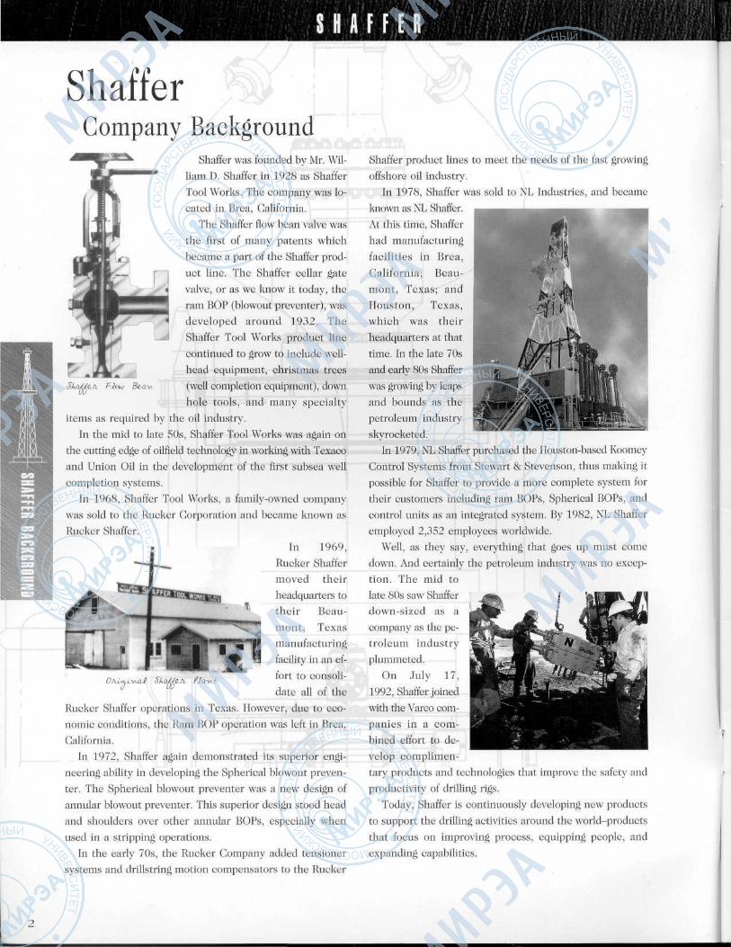
Shaffer was founded by Mr. Wil-liam D. Shaffer in 1928 as Shaffer
Tool Works. The company was lo-
cated in Brea, California.
The Shaffer flow bean valve was
the first of many patents which
became a part of the Shaffer prod-
uct line. The Shaffer cellar gate
valve, or as we know it today, the
ram BOP (blowout preventer), was
developed around 1932. The
Shaffer Tool Works product line
continued to grow to include well-
head equipment, Christmas trees
(well completion equipment), down
hole tools, and many specialty
items as required by the oil industry.
In the mid to late 50s, Shaffer Tool Works was again on
the cutting edge of oilfield technology in working with Texaco
and Union Oil in the development of the first subsea well
completion systems.
In 1968, Shaffer Tool Works, a family-owned company
was sold to the Rucker Corporation and became known as
Rucker Shaffer.
In 1969,Rucker Shaffer
moved their
headquarters totheir Beau-
mont, Texas
manufacturing
facility in an ef-
fort to consoli-
date all of theRucker Shaffer operations in Texas. However, due to eco-
nomic conditions, the Ram BOP operation was left in Brea,
California.
In 1972, Shaffer again demonstrated its superior engi-
neering ability in developing the Spherical blowout preven-
ter. The Spherical blowout preventer was a new design of
annular blowout preventer. This superior design stood head
and shoulders over other annular BOPs, especially when
used in a stripping operations.
In the early 70s, the Rucker Company added tensioner
systems and drillstring motion compensators to the Rucker
Shaffer product lines to meet the needs of the fast growing
offshore oil industry.
In 1978, Shaffer was sold to NL Industries, and became
known as NL Shaffer.
At this time, Shaffer
had manufacturing
facilities in Brea,
California; Beau-
mont, Texas; and
Houston, Texas,
which was their
headquarters at that
time. In the late 70sand early 80s Shaffer
was growing by leaps
and bounds as the
petroleum industryskyrocketed.
In 1979, NL Shaffer purchased the Houston-based Koomey
Control Systems from Stewart & Stevenson, thus making it
possible for Shaffer to provide a more complete system for
their customers including ram BOPs, Spherical BOPs, and
control units as an integrated system. By 1982, NL Shaffer
employed 2,352 employees worldwide.
Well, as they say, everything that goes up must come
down. And certainly the petroleum industry was no excep-
tion. The mid to
late 80s saw Shafferdown-sized as a
company as the pe-
troleum industry
plummeted.
On July 17,
1992, Shaffer joined
with the Varco com-panies in a com-
bined effort to de-
velop complimen-
tary products and technologies that improve the safety and
productivity of drilling rigs.
Today, Shaffer is continuously developing new products
to support the drilling activities around the world-products
that focus on improving process, equipping people, and
expanding capabilities.
Table of
Contents
S H A F F E R
Shaffer Company Background 2
Equipment Package Development 4
Underbalanced Drilling Products 5
Spherical BOPs 6
NXTRamBOP... . . .7
Blowout Prevention Equipment
Blowout Prevention Equipment 9
Ram Assemblies 10
Ram Assemblies 11
Koomey Control Systems 12
Koomey Control Systems 13
Auxiliary Equipment 14
Riser String Packages 15
Tensioners 16
Drill String Compensators 17
Crown-Mounted Compensators 18
Customer Support 19
Flow Products —
S H A F F E R
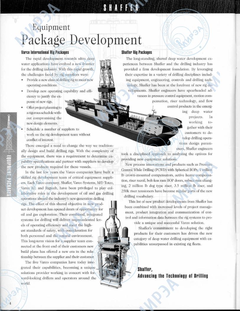
Equipment
Package DevelopmentVarco International Rig Packages
The rapid development towards ultra deep
water applications have evolved a new frontier
for the drilling industry. With this rapid growth,
the challenges faced by rig suppliers were:
• Provide a new class of drilling rig to meet new
operating conditions.
• Develop new operating capability and effi-
ciency to justify the ex-
pense of new rigs.
• Offer project planning to
a rigorous schedule with-
out compromising the
new design elements.
• Schedule a number of suppliers to
work on the rig development team without
conflict of interest.
There emerged a need to change the way we tradition-
ally design and build drilling rigs. With the complexity of
the equipment, there was a requirement to determine ca-
pability specifications and partner with suppliers to develop
the new products required for these vessels.
In the last few years the Varco companies have built a
skilled rig development team of critical equipment suppli-
ers. Each Varco company, Shaffer, Varco Systems, M/D Totco,Varco BJ, and Rigtech, have been privileged to play col-
laborative roles in the development of oil and gas drillingoperations aboard the industry's new-generation drilling
rigs. The effect of this shared objective in new prod-
uct development has opened doors of opportunity for
oil and gas exploration. Their combined, integrated
systems for drilling will deliver unprecedented lev-
els of operating efficiency and meet the high-
est standards of safety, with consideration for
both personnel and the natural environment.
This long-term vision for a supplier team con-
nected at the front end of their customers new
build plans has offered a new era in the rela-
tionship between the supplier and their customer.
The five Varco companies have today inte-
grated their capabilities, becoming a unique
solutions provider working in concert with for-
ward-looking drillers and operators around the
world.
Shaffer Rig PackagesThe long-standing, shared deep water development ex-
periences between Shaffer and the drilling industry has
provided a firm development foundation. By leveraging
their expertise in a variety of drilling disciplines includ-
ing equipment, engineering, controls and drilling tech-
nology, Shaffer has been at the forefront of new rig de-
velopments. Shaffer engineers have spearheaded ad-
vances in pressure control equipment, motion com-
pensation, riser technology, and flowcontrol products in the emerg-
ing deep water
projects. Inworking to-
gether with their
customers to de-
velop drilling opera-
tions design param-
eters, Shaffer engineers
took a disciplined approach to analyzing the options for
providing new equipment solutions.
New process innovations and products such as Pressure
Control While Drilling (PCWD) with Spherical BOPs, 1 million
Ib crown-mounted compensators, active heave compensa-
tion, riser recoil, bolt-less ram BOP doors, subsea ram chang-
ing, 2 million Ib dog type riser, 3.5 million Ib riser, and
250k riser tensioners have become regular parts of the new
drilling vocabulary.
This list of new product developments from Shaffer has
been combined with increased levels of project manage-
ment, product integration and communication of con-
trol and information data between the rig systems to pro-
vide a unique and successful Varco solution.
Shaffer's commitment to developing the right
products for their customers has driven the new
category of deep water drilling equipment with ca-
pabilities unsurpassed in existing rig fleets.
Shaffer,Advancing the Technology of Drilling
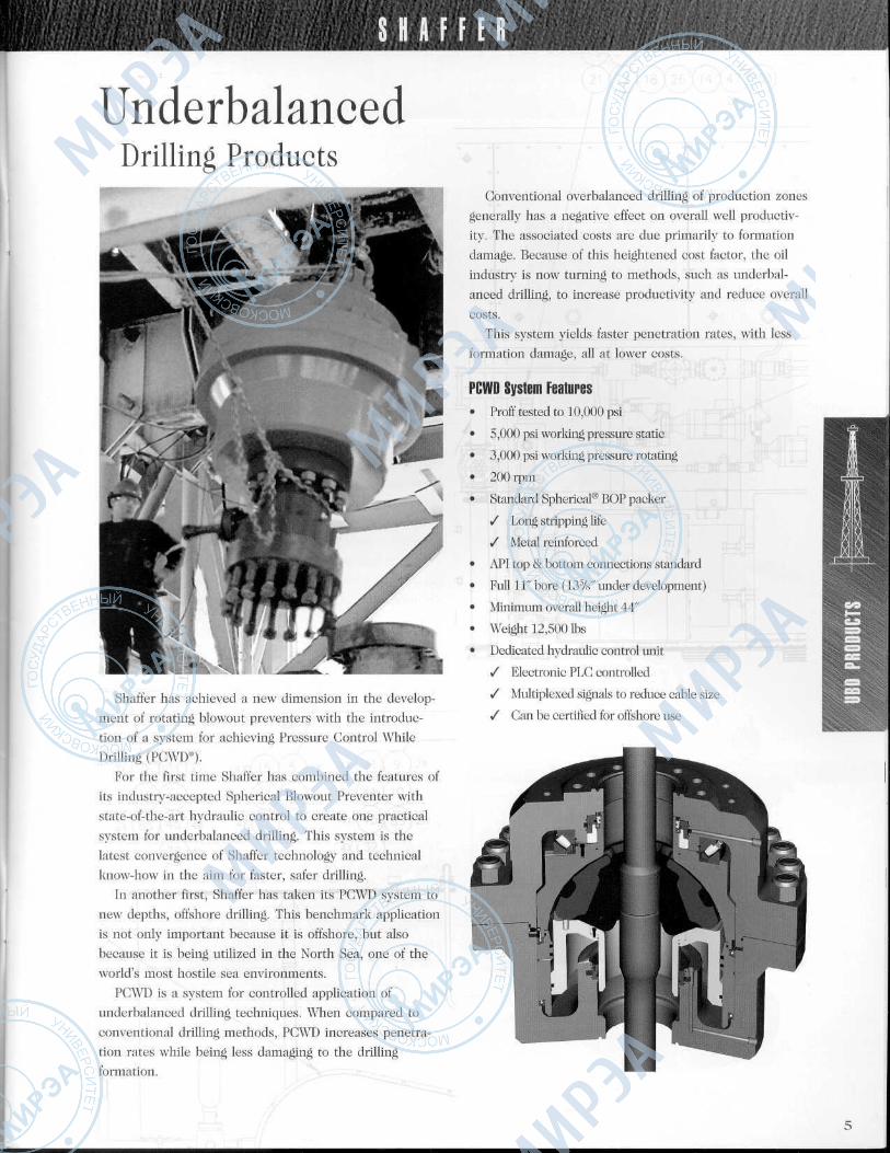
UnderbalancedDrilling Products
Shaffer has achieved a new dimension in the develop-
ment of rotating blowout preventers with the introduc-
tion of a system for achieving Pressure Control While
Drilling (PCWD®).
For the first time Shaffer has combined the features of
its industry-accepted Spherical Blowout Preventer with
state-of-the-art hydraulic control to create one practical
system for underbalanced drilling. This system is the
latest convergence of Shaffer technology and technical
know-how in the aim for faster, safer drilling.
In another first, Shaffer has taken its PGWD system to
new depths, offshore drilling. This benchmark application
is not only important because it is offshore, but also
because it is being utilized in the North Sea, one of the
world's most hostile sea environments.
PGWD is a system for controlled application of
underbalanced drilling techniques. When compared to
conventional drilling methods, PGWD increases penetra-
tion rates while being less damaging to the drillingformation.
Conventional overbalanced drilling of production zones
generally has a negative effect on overall well productiv-
ity. The associated costs are due primarily to formation
damage. Because of this heightened cost factor, the oil
industry is now turning to methods, such as underbal-
anced drilling, to increase productivity and reduce overall
costs.This system yields faster penetration rates, with less
formation damage, all at lower costs.
PCWD System Features• Proff tested to 10,000 psi
• 5,000 psi working pressure static
• 3,000 psi working pressure rotating
• 200 rpm
• Standard Spherical® BOP packer
/ Long stripping life
/ Metal reinforced
• API top & bottom connections standard
• Full 11" bore (13%" under development)
• Minimum overall height 44"
• Weight 12,500 Ibs
• Dedicated hydraulic control unit
/ Electronic PLC controlled
/ Multiplexed signals to reduce cable size
/ Can be certified for offshore use
S H A F F E R
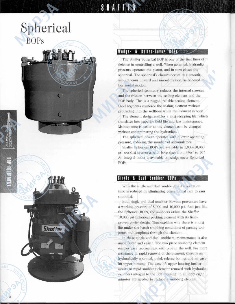
SphericalBOPs
W e d g e - & B e l t e d - C o v e r B O P sThe Shaffer Spherical BOP is one of the first lines of
defense in controlling a well. When actuated, hydraulic
pressure operates the piston, and in turn closes the
spherical. The spherical's closure occurs in a smooth,
simultaneous upward and inward motion, as opposed to
horizontal motion.
The spherical geometry reduces the internal stresses
and the friction between the sealing element and the
BOP body. This is a rugged, reliable sealing element.
Steel segments reinforce the sealing element without
protruding into the wellbore when the element is open.The element design enables a long stripping life, which
translates into superior field life and less maintenance.
Maintenance is easier as the element can be changed
without contaminating the hydraulics.
The spherical design operates with a lower operating
pressure, reducing the number of accumulators.
Shaffer Spherical BOPs are available in 1,000-10,000
psi working pressures with bore sizes from 4 Vie" to 30".
An integral outlet is available on wedge cover Spherical
BOPs.
S i n g l e & D u a l hillir B O P sWith the single and dual snubbing BOPs operation
time is reduced by eliminating conventional ram to ram
snubbing.
Both single and dual snubber blowout preventers have
a working pressure of 5,000 and 10,000 psi. And just like
the Spherical BOPs, the snubbers utilize the Shaffer
10,000 psi Spherical packing element with its field-
proven cavity design. That explains why there is a long
life under the harsh snubbing conditions of passing tool
joints and couplings through the element.
In these single and dual snubbers, maintenance is also
made faster and easier. The two piece snubbing element
enables easy replacement with pipe in the well. For more
assistance in rapid removal of the element, there is an
hydraulically-operated, quick-release bonnet and an easy-
lift upper housing. The easy-lift upper housing further
assists in rapid snubbing element removal with hydraulic
cylinders integral to the BOP housing. In all, only eight
minutes are needed to replace a snubbing element.
S H A F F E R. - - . . . , . • .
;•'-,'••..<: .-.г tvv ,!t; Л/ ,;
4, ;'V»V ,
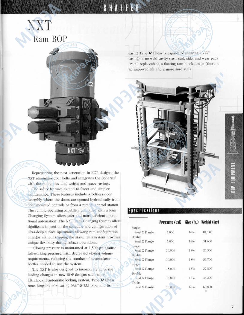
NXTRam BOP
Representing the next generation in BOP designs, the
NXT eliminates door bolts and integrates the Spherical
with the rams, providing weight and space savings.
The safety features extend to faster and simpler
maintenance. These features include a boltless door
assembly where the doors are opened hydraulically from
door mounted controls or from a remote control station.
The remote operating capability combined with a Ram
Changing System offers safer and more efficient opera-
tional automation. The NXT Ram Changing System offers
significant impact on the schedule and configuration of
ultra-deep subsea operations allowing ram configuration
changes without tripping the stack. This system provides
unique flexibility during subsea operations.
Closing pressure is maintained at 1,500 psi against
full-working pressure, with decreased closing volume
requirements, reducing the number of accumulator
bottles needed to run the system.
The NXT is also designed to incorporate all of the
leading changes in new BOP designs such as an
UltraLock II automatic locking system, Type V Shear
rams (capable of shearing 6 W S-135 pipe, and its
casing Type V Shear is capable of shearing 13-W
casing), a no-weld cavity (seat seal, side, and wear pads
are all replaceable), a floating ram block design (there is
an improved life and a more sure seal).
S p e c i f i c a t i o n s
Single
Stud X Flange
Double
Stud X Flange
Single
Stud X Flange
Double
Stud X Flange
Single
Stud X Flange
Double
Stud X Flange
Triple
Stud X Flange
Pressure (psi) Size (in.) Weight (Ibs)
5,000 18% 18,5 00
5,000 18% 31,600
10,000 18% 23,500
10,000 18% 36,700
15,000 18% 32,800
15,000 18% 48,300
15,000 18% 63,800
S H A F F E R
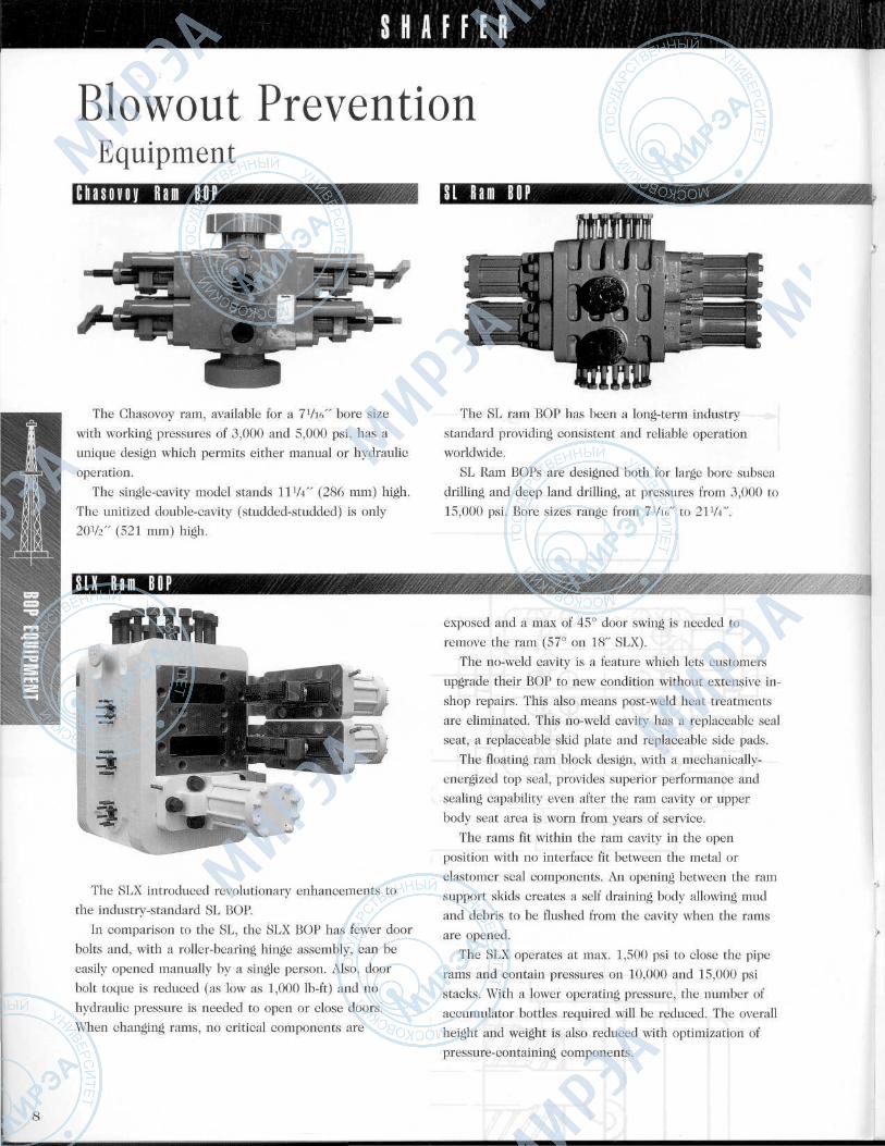
Blowout PreventionEquipment
C n a s o v o y R a m B O P
The Ghasovoy ram, available for a 7Vie" bore size
with working pressures of 3,000 and 5,000 psi, has aunique design which permits either manual or hydraulic
operation.
The single-cavity model stands HVi" (286 mm) high.
The unitized double-cavity (studded-studded) is only
2042" (521 mm) high.
S L X R a m B O P
The SLX introduced revolutionary enhancements to
the industry-standard SL BOP.
In comparison to the SL, the SLX BOP has fewer door
bolts and, with a roller-bearing hinge assembly, can be
easily opened manually by a single person. Also, door
bolt toque is reduced (as low as 1,000 Ib-ft) and no
hydraulic pressure is needed to open or close doors.
When changing rams, no critical components are
I I R a m B O P
The SL ram BOP has been a long-term industry
standard providing consistent and reliable operationworldwide.
SL Ram BOPs are designed both for large bore subsea
drilling and deep land drilling, at pressures from 3,000 to
15,000 psi. Bore sizes range from 7Vie" to 21V4".
exposed and a max of 45° door swing is needed to
remove the ram (57° on 18" SLX).
The no-weld cavity is a feature which lets customers
upgrade their BOP to new condition without extensive in-
shop repairs. This also means post-weld heat treatments
are eliminated. This no-weld cavity has a replaceable seal
seat, a replaceable skid plate and replaceable side pads.
The floating ram block design, with a mechanically-
energized top seal, provides superior performance and
sealing capability even after the ram cavity or upper
body seat area is worn from years of service.
The rams fit within the ram cavity in the open
position with no interface fit between the metal or
elastomer seal components. An opening between the ram
support skids creates a self draining body allowing mud
and debris to be flushed from the cavity when the rams
are opened.
The SLX operates at max. 1,500 psi to close the pipe
rams and contain pressures on 10,000 and 15,000 psi
stacks. With a lower operating pressure, the number of
accumulator bottles required will be reduced. The overall
height and weight is also reduced with optimization of
pressure-containing components.
8
НИНННШшцПНННННН:
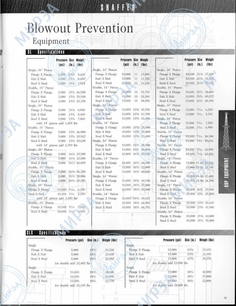
Blowout PreventionEquipment
S I S p e c i f i c a t i o n sPressure Size Weight
(psi) (in.) (Ibs)Single, 10" Piston
Flange X Flange 3,000 13% 8,430
Hub X Hub 3,000 13% 8,400
Stud X Stud 3,000 13% 7,924
Double, 10" Piston
Flange X Flange 3,000 13% 16,500
Hub X Hub 3,000 13% 15,548
Stud X Stud 3,000 13% 15,350
Single, 10" Piston
Flange X Flange 5,000 13% 8,985
Hub X Hub 5,000 13% 8,400
Stud X Stud 5,000 13% 7,800
with 14' piston add 1,400 Ihs
Double, 10" Piston
Flange X Flange 5,000 13% 16,900
Hub X Hub 5,000 13V» 15,912
Stud X Stud 5,000 13% 15,620
with 14' piston add 2,700 Ibs
Single, 10" Piston
Flange X Flange 5,000 163/4 15,500
Hub X Hub 5,000 163/4 12,850
Stud X Stud 5,000 163/4 14,095
Double, 10" Piston
Flange X Flange 5,000 16% 26,250
Hub X Hub 5,000 16% 25,886
Stud X Stud 5,000 16% 25,285
Single, 10" Piston
Flange X Flange 10,000 7Vi6 6,200
Stud X Stud 10,000 7Vi<, 5,550
with If piston add 1,350 Ibs
Double, 10" Piston
Flange X Flange 10,000 7Vi6 9,830
Stud X Stud 10,000 7Vif, 9,900
Pressure Size Weight(psi) (in.) (Ibs)
Single, 14" Piston
Flange X Flange 10,000 11 13,000
Hub X Hub 10,000 11 11,708
Stud X Stud 10,000 11 11,100
Double, 14" Piston
Flange X Flange 10,000 11 21,790
Hub X Hub 10,000 11 21,560
Stud X Stud 10,000 11 20,550
Single, 14" Piston
Flange X Flange 10,000 13% 15,550
Hub X Hub 10,000 13% 13,700
Stud X Stud 10,000 13% 13,200
Double, 14" Piston
Flange X Flange 10,000 13% 25,500
Hub X Hub 10,000 13% 23,800
Stud X Stud 10,000 13% 23,400
Single, 14" Piston
Flange X Flange 10,000 16% 28,500
Hub X Hub 10,000 16% 26,600
Stud X Stud 10,000 16% 25,828
Double, 14" Piston
Flange X Flange 10,000 16% 44,300
Hub X Hub 10,000 16% 42,000
Stud X Stud 10,000 16% 40,600
Single, 14" Piston
Flange X Flange 10,000 18% 30,700
Hub X Hub 10,000 18% 27,100
Stud X Stud 10,000 18% 25,300
Double, 14" Piston
Flange X Flange 10,000 18% 49,117
Hub X Hub 10,000 183/4 44,903
Stud X Stud 10,000 183/4 44,792
Pressure Size Weight(psi) (in.) (Ibs)
Single, 14" Piston
Flange X Flange 10,000 21% 37,600
Hub X Hub 10,000 213/4 31,800
Stud X Stud 10,000 213/4 31,130
Double, 14" Piston
Flange X Flange 10,000 21% 54,860
Hub X Hub 10,000 213/4 49,372
Stud X Stud 10,000 21% 48,705
Single, 10" Piston
Flange X Flange 15,000 7Vi6 6,200 ^_^_
Stud X Stud 15,000 7Vi6 5,781 Jf••' 'Hi
Single, 14" Piston Щ' Ш
Flange X Flange 15,000 7Vi6 7,550 :;|
Stud X Stud 15,000 7Vi6 6,900 Е1Ш
Double, 10" Piston НИяВ^К л 1 1 KHB
Flange X Flange 15,000 7Vi6 10,300 H §•
Stud X Stud 15,000 7Vio 10,016
Double, 14" Piston•••••••ЯFlange X Flange 15,000 7Vi6 12,950
Stud X Stud 15,000 7Vi6 12,350
Single, 14" Piston
Flange X Flange 15,000 11-86 16,500
Stud X Stud 15,00011-8613,700 В||Я
Double, 14" Piston
Flange X Flange 15,000 1 1-86 27,400
Stud X Stud 15,000 11-86 24,700
Single, 14" Piston
Flange X Flange 15,000 13% 29,050
Stud X Stud 15,000 13% 25,860
Double, 14" Piston
Flange X Flange 15,000 13% 45,130
Stud X Stud 15,000 13% 41,940
Double, 14" Piston
Flange X Flange 15,000 183/4 60,000
Stud X Stud 15,000 183/4 50,000
••••«••••• ||мв̂ ши|>сж^^ши.(,_аж.S I X S p e c i f i c a t i o n sPressure (psi) Size (in.) Weight (Ibs) Pressure (psi) Size (in.) Weight (Ibs)
Single Single
Flange X Flange 5,000 18-% 24,760 Flange X Flange 15,000 13% 23,670
Hub X Hub 5,000 18-% 23,600 Hub X Hub 15,000 13% 21,300
Stud X Stud 5,000 18% 22,285 Stud X Stud 15,000 13% 20,270
(or double add 15,485 Ibs for double add 13,090 Ibs
Single Single
Flange X Flange 10,000 18% 28,640 Flange X Flange 15,000 18% 42,000
Hub X Hub 10,000 18% 24,890 Hub X Hub 15,000 18% 37,000
Stud X Stud 10,000 18% 23,770 Stud X Stud 15,000 18% 32,000
for double add 16,100 Ibs for double add 18,000 Ibs
S H A F F E R
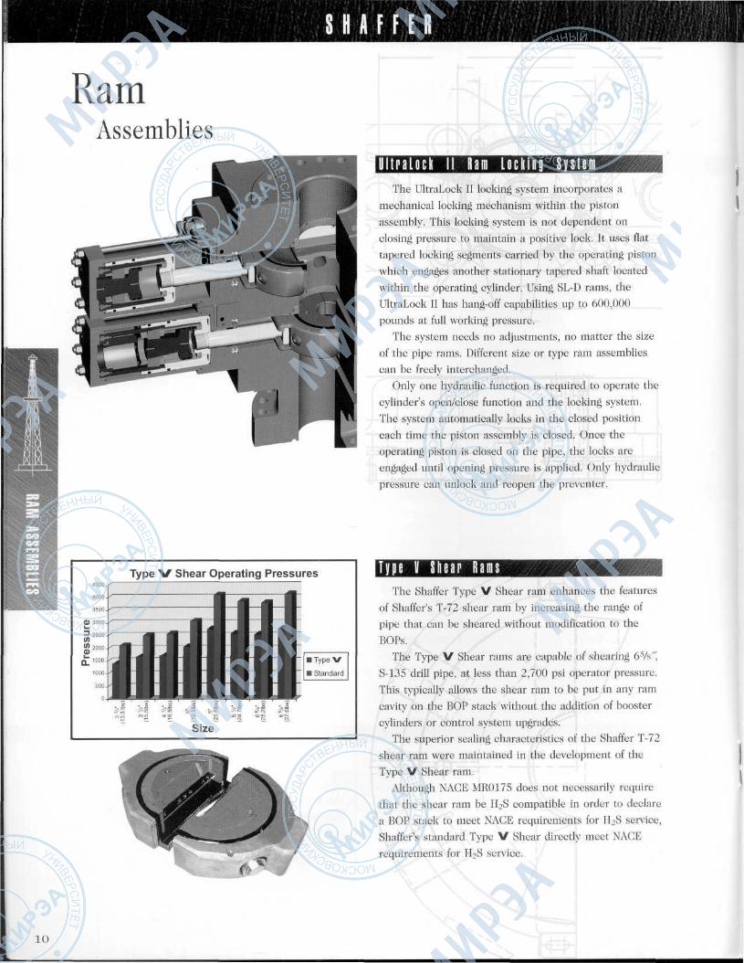
RamAssemblies
Type V Shear Operating Pressures4500-,
4000-
3500-
3000.
2500-
2000-
1500-
1000-
500-
0
I I II I I 1 I I I
Size
l l l t r a L o c k I I R a m L o c k i n g S y s t e mThe UltraLock II locking system incorporates a
mechanical locking mechanism within the piston
assembly. This locking system is not dependent on
closing pressure to maintain a positive lock. It uses flat
tapered locking segments carried by the operating piston
which engages another stationary tapered shaft located
within the operating cylinder. Using SL-D rams, the
UltraLock II has hang-off capabilities up to 600,000
pounds at full working pressure.
The system needs no adjustments, no matter the size
of the pipe rams. Different size or type ram assemblies
can be freely interchanged.
Only one hydraulic function is required to operate the
cylinder's open/close function and the locking system.
The system automatically locks in the closed position
each time the piston assembly is closed. Once the
operating piston is closed on the pipe, the locks are
engaged until opening pressure is applied. Only hydraulic
pressure can unlock and reopen the preventer.
T y p e V Шаг R a m sThe Shaffer Type V Shear ram enhances the features
of Shaffer's T-72 shear ram by increasing the range of
pipe that can be sheared without modification to the
BOPs.
The Type V Shear rams are capable of shearing 65ЛГ,
S-135 drill pipe, at less than 2,700 psi operator pressure.
This typically allows the shear ram to be put in any ram
cavity on the BOP stack without the addition of booster
cylinders or control system upgrades.
The superior sealing characteristics of the Shaffer T-72
shear ram were maintained in the development of the
Type V Shear ram.
Although NAGE MR0175 does not necessarily require
that the shear ram be H2S compatible in order to declare
a BOP stack to meet NAGE requirements for H2S service,
Shaffer's standard Type V Shear directly meet NAGE
requirements for H2S service.
10
S H A F F E R
RamAssemblies
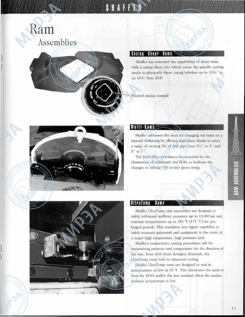
C a s i n o S h e a r R a m sShaffer has extended the capabilities of shear rams
with a casing shear ram which meets the specific cuttingneeds to physically shear casing tubulars up to 133/s"inan 18W bore BOP.
Sheared casing example
M u l t i - R a m sShaffer addresses the need for changing out rams on a
tapered drillstring by offering Multi-Ram blocks to covera range of varying IDs of drill pipe from 3lh" to 5"and5" to 1".
The Multi-Ram introduces the potential for theelimination of additional ram BOPs to facilitate thechanges in tubular OD on any given string.
Ittriflii R a m sShaffer UltraTemp ram assemblies are designed to
safely withstand wellbore pressures up to 15,000 psi andextreme temperatures up to 350 °F (177 °G) for pro-longed periods. This translates into rigsite capability tosafely evacuate personnel and equipment in the event ofa major high temperature, high pressure kick.
Shaffer's conservative testing procedures call formaintaining pressure and temperature for the duration ofthe test. Even with these stringent demands, theUltraTemp rams hold in witnessed testing.
Shaffer UltraTemp rams are designed to seal intemperatures as low as 20 °F. This eliminates the need toheat the BOPs and/or the test medium when the surfaceambient temperature is low.
11
S H A F F E R
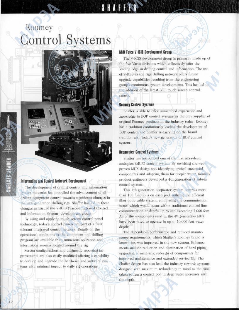
Koomey
Control Systems
Information and Control Network DevelopmentThe development of drilling control and information
system networks has propelled the advancement of alldrilling equipment control towards significant changes in
the new generation drilling rigs. Shaffer has led in these
changes as part of the V-IGIS (Varco-Integrated Control
and Information System) development group.
By using and applying touch screen control panel
technology, today's control panels are part of a fault
tolerant integrated control network. Details on the
operational conditions of the equipment and drilling
program are available from numerous operation and
information screens located around the rig.
Screen configurations and diagnostic reporting im-
provements are also easily modified offering a capability
to develop and upgrade the hardware and software sys-
tems with minimal impact to daily rig operations.
M/D Totco V-ICIS Development GroupThe V-IGIS development group is primarily made up of
the five Varco divisions which collectively offer the
leading edge in drilling control and information. The use
of V-IGIS as the rig's drilling network offers future
upgrade capabilities resulting from the engineering
group's continuous system developments. This has led to
the addition of the latest BOP touch screen control
panels.
Koomey Control SystemsShaffer is able to offer unmatched experience and
knowledge in BOP control systems as the only supplier of
original Koomey products in the industry today. Koomey
has a tradition continuously leading the development of
BOP control and Shaffer is carrying on the brand
tradition with today's new generation of BOP control
systems.
Deepwater Control SystemsShaffer has introduced one of the first ultra-deep
multiplex (MUX) control system. By revisiting the well-
proven MUX design and identifying critical successful
components and adapting them for deeper water, Koomey
product engineers developed a 4th generation of subsea
control system.This 4th generation deepwater system controls more
than 100 functions on each pod, utilizing the efficient
fiber optic cable system, eliminating the communication
issues which would occur with a traditional control line
communication at depths up to and exceeding 7,000 feet.
All of the components used in the 4th generation MUX
have been rated to operate in up to 10,000 feet water
depths.
The dependable performance and reduced mainte-
nance requirements, which Shaffer's Koomey brand is
known for, was improved in the new system. Enhance-
ments include reduction and elimination of hard piping,
upgrading of materials, redesign of components forimproved maintenance and extended service life. The
Shaffer design has also lead the industry towards systems
designed with maximum redundancy in mind as the time
taken to run a control pod in deep water increases with
the depth.
12
S H A F F E R
Koomey
Control Systems
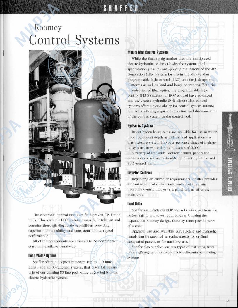
The electronic control unit uses field-proven GE Fanuc
PLCs. This system's PLG architecture is fault tolerant and
contains thorough diagnostic capabilities, providing
superior maintainability and consistent uninterrupted
performance.
All of the components are selected to be nonpropri-
etary and available worldwide.
Deep Water OptionsShaffer offers a deepwater system (up to 110 func-
tions), and an 80-function system, that takes full advan-
tage of our existing 80-line pod, while upgrading it to an
electro-hydraulic system.
Minute Man Control SystemsWhile the floating rig market uses the multiplexed
electro-hydraulic or direct-hydraulic systems, high
specification jack-ups are applying the lessons of the 4th
Generation MUX systems for use in the Minute Man
programmable logic control (PLG) unit for jack-ups and
platforms as well as land and barge operations. With the
introduction of fiber optics, the programmable logic
control (PLG) systems for BOP control have advanced
and the electro-hydraulic (EH) Minute-Man control
systems offers unique ability for control system automa-
tion while offering a quick connection and disconnection
of the control system to the control pod.
Hydraulic SystemsDirect hydraulic systems are available for use in water
under 5,500-feet depth as well as land applications. A
bias-pressure system improves response times of hydrau-
lic systems in water depths in excess of 3,000х.
A variety of test units, workover units, panels and
other options are available utilizing direct hydraulic and
PLG control units.
Diverter ControlsDepending on customer requirements, Shaffer provides
a diverter control system independent of the main
hydraulic control unit or as a panel driven off of the
main unit.
Land UnitsShaffer manufactures BOP control units sized from the
largest rigs to workover requirements. Utilizing the
dependable Koomey design, these systems provide years
of service.
Upgrades are also available. Air, electric and hydraulic
panels can be supplied as replacements for original
antiquated panels, or for auxiliary use.
Shaffer also supplies various types of test units, from
pumping/gauging units to complete self-contained testing
systems.
13
S H A F F E R • ' , ' V . • ' »
Auxiliary
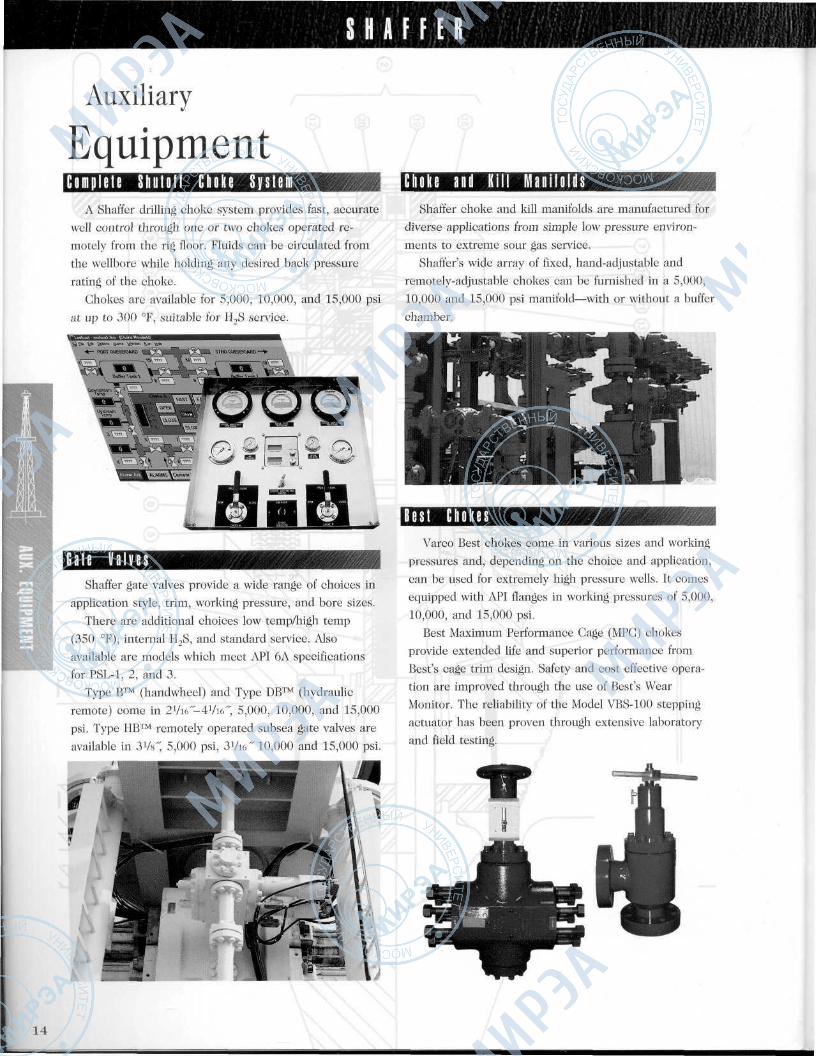
EquipmentC o m p l e t e S h u t o f f C h o k e S y s t e m
A Shaffer drilling choke system provides fast, accurate
well control through one or two chokes operated re-
motely from the rig floor. Fluids can be circulated from
the wellbore while holding any desired back pressure
rating of the choke.
Chokes are available for 5,000, 10,000, and 15,000 psi
at up to 300 °F, suitable for H2S service.
G a t e V a l v e sShaffer gate valves provide a wide range of choices in
application style, trim, working pressure, and bore sizes.
There are additional choices low temp/high temp
(350 °F), internal H2S, and standard service. Also
available are models which meet API 6A specifications
for PSL-1, 2, and 3.Type B™ (handwheel) and Type DB™ (hydraulic
remote) come in 2Vi6"-4Vi6", 5,000, 10,000, and 15,000
psi. Type HB™ remotely operated subsea gate valves are
available in 3Vs" 5,000 psi, 3Vi6" 10,000 and 15,000 psi.
C h o k e a n d Ki l l M a n i f o l d sShaffer choke and kill manifolds are manufactured for
diverse applications from simple low pressure environ-
ments to extreme sour gas service.
Shaffer's wide army of fixed, hand-adjustable and
remotely-adjustable chokes can be furnished in a 5,000,
10,000 and 15,000 psi manifold—with or without a buffer
chamber.
B e s t C h o k e sVarco Best chokes come in various sizes and working
pressures and, depending on the choice and application,
can be used for extremely high pressure wells. It comes
equipped with API flanges in working pressures of 5,000,
10,000, and 15,000 psi.Best Maximum Performance Gage (MPG) chokes
provide extended life and superior performance from
Best's cage trim design. Safety and cost effective opera-
tion are improved through the use of Best's Wear
Monitor. The reliability of the Model VBS-100 steppingactuator has been proven through extensive laboratory
and field testing.
14
S H A F F E R
Riser StringPackages
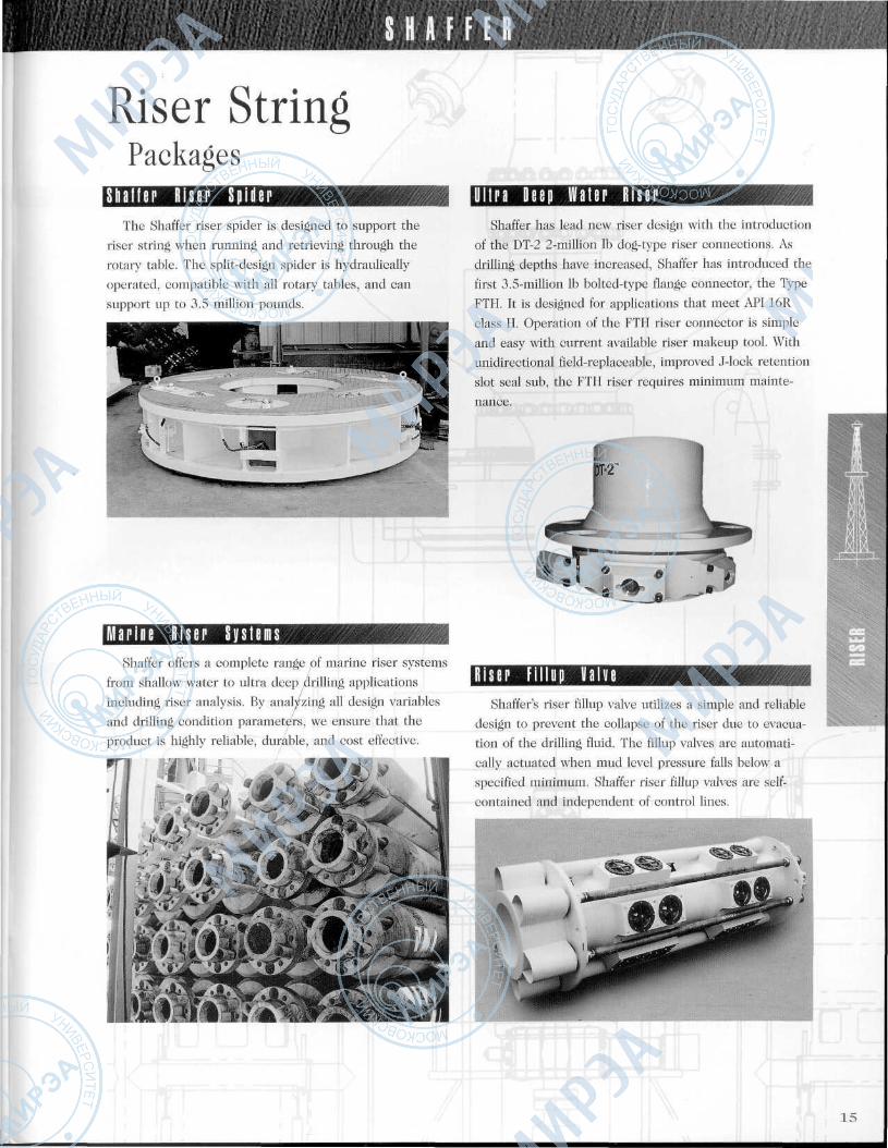
S h a f f e r R i s e r S p i d e rThe Shaffer riser spider is designed to support the
riser string when running and retrieving through the
rotary table. The split-design spider is hydraulically
operated, compatible with all rotary tables, and can
support up to 3.5 million pounds.
M a r i n e R i s e r S y s t e m sShaffer offers a complete range of marine riser systems
from shallow water to ultra deep drilling applications
including riser analysis. By analyzing all design variables
and drilling condition parameters, we ensure that theproduct is highly reliable, durable, and cost effective.
U l t r a D e e p w a t e r R i s e rShaffer has lead new riser design with the introduction
of the DT-2 2-million Ib dog-type riser connections. As
drilling depths have increased, Shaffer has introduced the
first 3.5-million Ib bolted-type flange connector, the Type
FTH. It is designed for applications that meet API 16R
class II. Operation of the FTH riser connector is simple
and easy with current available riser makeup tool. Withunidirectional field-replaceable, improved J-lock retention
slot seal sub, the FTH riser requires minimum mainte-
nance.
R i s e r F i l l up V a l v eShaffer's riser fillup valve utilizes a simple and reliable
design to prevent the collapse of the riser due to evacua-
tion of the drilling fluid. The fillup valves are automati-
cally actuated when mud level pressure falls below a
specified minimum. Shaffer riser fillup valves are self-
contained and independent of control lines.
• • • ' . • ' : • . ' • . ' ' \ - • • • > . ' " ' .
15
S H A F F E R
Tensioners
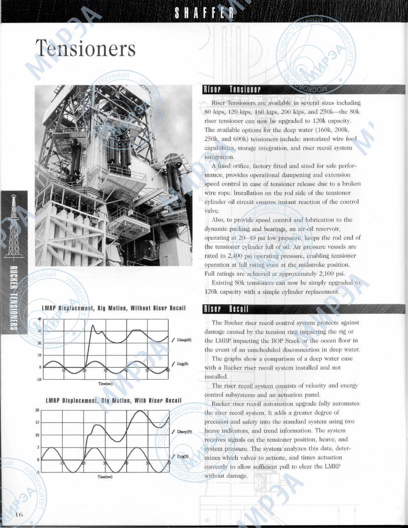
LMRP Displacement, Rig Motion, W i t h o u t Riser R e c o i l
30
20
10
О
-10
20
15
10
5
О
Tuae(sec)
LMRP Displacement, Rig Motion, With Riser Recoil
/ \1
/~N
1f \\Л 1
ч у
^
ч/
/ Л
^/ \1 5
\ J
^
\/
/ Dtaq>(fl)
/ Drigfft)
16
R i s e r riitiflivRiser Tensioners are available in several sizes including
80 kips, 120 kips, 160 kips, 200 kips, and 250k—the 8()k
riser tensioner can now be upgraded to 120k capacity.
The available options for the deep water (160k, 200k,
250k, and 600k) tensioners include: motorized wire feed
capabilities, storage integration, and riser recoil system
integration.
A fixed orifice, factory fitted and sized for safe perfor-
mance, provides operational dampening and extension
speed control in case of tensioner release due to a broken
wire rope. Installation on the rod side of the tensioner
cylinder oil circuit ensures instant reaction of the control
valve.
Also, to provide speed control and lubrication to the
dynamic packing and bearings, an air-oil reservoir,
operating at 20-40 psi low pressure, keeps the rod end of
the tensioner cylinder full of oil. Air pressure vessels are
rated to 2,400 psi operating pressure, enabling tensioner
operation at full rating even at the midstroke position.
Full ratings are achieved at approximately 2,100 psi.
Existing 80k tensioners can now be simply upgraded to
120k capacity with a simple cylinder replacement.
R i s e r R e c o i lThe Rucker riser recoil control system protects against
damage caused by the tension ring impacting the rig or
the LMRP impacting the BOP Stack or the ocean floor in
the event of an unscheduled disconnection in deep water.
The graphs show a comparison of a deep water case
with a Rueker riser recoil system installed and not
installed.
The riser recoil system consists of velocity and energy
control subsystems and an actuation panel.
Rucker riser recoil automation upgrade fully automates
the riser recoil system. It adds a greater degree of
precision and safety into the standard system using two
heave indicators, and trend information. The system
receives signals on the tensioner position, heave, and
system pressure. The system analyzes this data, deter-
mines which valves to actuate, and times actuation
correctly to allow sufficient pull to clear the LMRP
without damage.
S H A F F E R ' '- t \''. '•'•' if ':
Drill StringCompensators
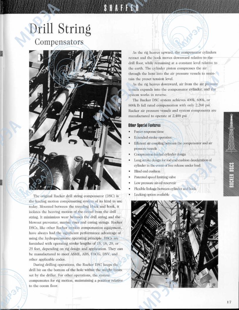
The original Rucker drill string compensator (DSG) is
the leading motion compensating system of its kind in use
today. Mounted between the traveling block and hook, it
isolates the heaving motion of the vessel from the drill
string. It minimizes wear between the drill string and the
blowout preventer, marine riser and casing strings. Rucker
DSGs, like other Rucker motion compensation equipment,
have always had the significant performance advantage of
using the hydropneumatic operating principle. DSCs are
furnished with operating stroke lengths of 15, 18, 20, or
25 feet, depending on rig design and application. They can
be manufactured to meet ASME, ABS, USGG, DNV, and
other applicable codes.
During drilling operations, the Rucker DSG keeps the
drill bit on the bottom of the hole within the weight limits
set by the driller. For other operations, the system
compensates for rig motion, maintaining a position relative
to the ocean floor.
As the rig heaves upward, the compensator cylinders
retract and the hook moves downward relative to the
drill floor, while remaining at a constant level relative to
the earth. The cylinder piston compresses the air
through the hose into the air pressure vessels to main-
tain the preset tension level.
As the rig heaves downward, air from the air pressure
vessels expands into the compensator cylinder, and the
system works in reverse.The Rucker DSG system achieves 400k, 600k, or
800k Ib full rated compensation with only 2,260 psi.
Rucker air pressure vessels and system components are
manufactured to operate at 2,400 psi.
Other Special Features• Faster response time
• Extended stroke operation
• Efficient air coupling between the compensator and air
pressure vessels
• Compression-loaded cylinder design
• Long stroke design for rod end cushion deceleration of
cylinder in the event of free release under load.
• Blind end cushion
• Patented speed limiting valve
• Low pressure air-oil reservoir
• Flexible linkage between cylinder and hook
• Locking option available
17
S H A F F E R
Crown-MountedCompensators
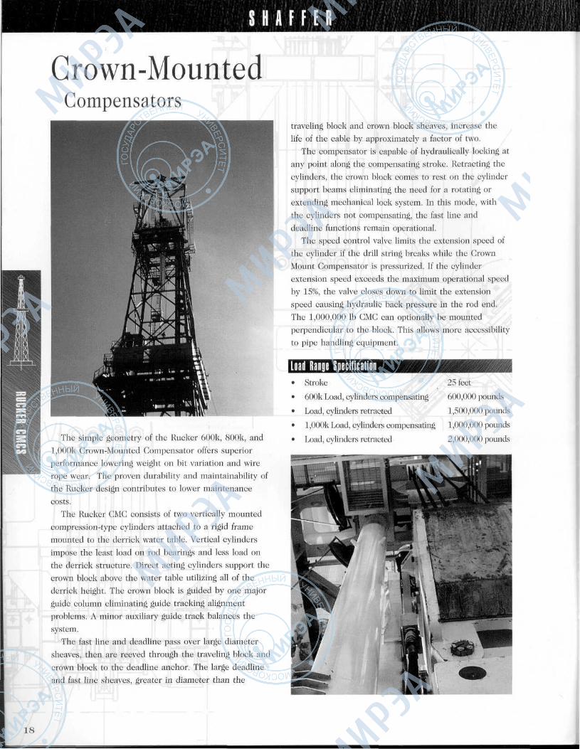
The simple geometry of the Rucker 600k, 800k, and
1,000k Crown-Mounted Compensator offers superiorperformance lowering weight on bit variation and wire
rope wear. The proven durability and maintainability of
the Rucker design contributes to lower maintenance
costs.The Rucker CMC consists of two vertically mounted
compression-type cylinders attached to a rigid frame
mounted to the derrick water table. Vertical cylinders
impose the least load on rod bearings and less load on
the derrick structure. Direct acting cylinders support the
crown block above the water table utilizing all of the
derrick height. The crown block is guided by one major
guide column eliminating guide tracking alignment
problems. A minor auxiliary guide track balances the
system.
The fast line and deadline pass over large diameter
sheaves, then are reeved through the traveling block and
crown block to the deadline anchor. The large deadline
and fast line sheaves, greater in diameter than the
traveling block and crown block sheaves, increase the
life of the cable by approximately a factor of two.
The compensator is capable of hydraulically locking at
any point along the compensating stroke. Retracting the
cylinders, the crown block comes to rest on the cylinder
support beams eliminating the need for a rotating or
extending mechanical lock system. In this mode, with
the cylinders not compensating, the fast line and
deadline functions remain operational.The speed control valve limits the extension speed of
the cylinder if the drill string breaks while the Crown
Mount Compensator is pressurized. If the cylinder
extension speed exceeds the maximum operational speed
by 15%, the valve closes down to limit the extension
speed causing hydraulic back pressure in the rod end.
The 1,000,000 Ib CMC can optionally be mounted
perpendicular to the block. This allows more accessibility
to pipe handling equipment.
Load Range Speci l icat ionStroke 25 feet
600k Load, cylinders compensating 600,000 pounds
Load, cylinders retracted
1,000k Load, cylinders compensating
Load, cylinders retracted
1,500,000 pounds
1,000,000 pounds
2,000,000 pounds
18
S H A F F E R
CustomerSupport
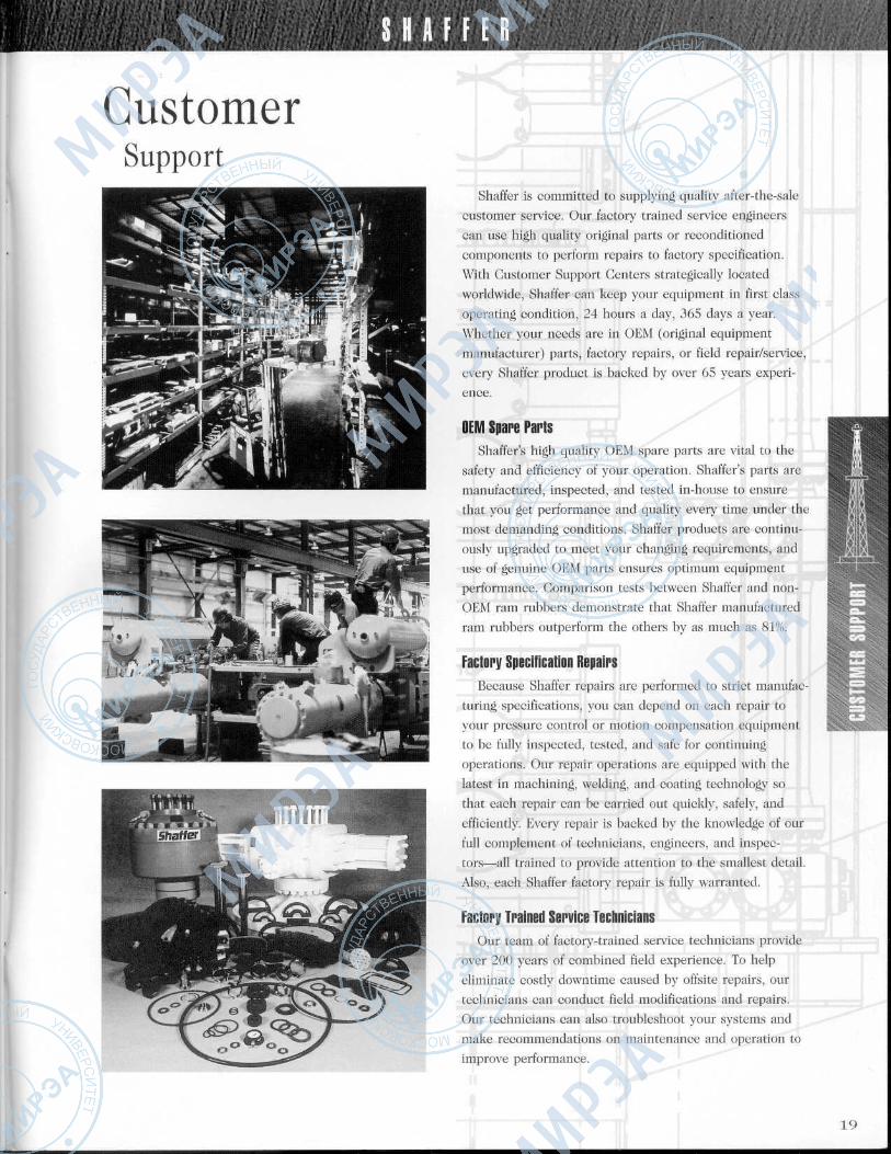
Shaffer is committed to supplying quality after-the-sale
customer service. Our factory trained service engineers
can use high quality original parts or reconditioned
components to perform repairs to factory specification.
With Customer Support Centers strategically located
worldwide, Shaffer can keep your equipment in first class
operating condition, 24 hours a day, 365 days a year.
Whether your needs are in OEM (original equipment
manufacturer) parts, factory repairs, or field repair/service,
every Shaffer product is backed by over 65 years experi-
ence.
OEM Spare PartsShaffer's high quality OEM spare parts are vital to the
safety and efficiency of your operation. Shaffer's parts are
manufactured, inspected, and tested in-house to ensure
that you get performance and quality every time under the
most demanding conditions. Shaffer products are continu-
ously upgraded to meet your changing requirements, and
use of genuine OEM parts ensures optimum equipmentperformance. Comparison tests between Shaffer and non-
OEM ram rubbers demonstrate that Shaffer manufactured
ram rubbers outperform the others by as much as 81%.
Factory Specification RepairsBecause Shaffer repairs are performed to strict manufac-
turing specifications, you can depend on each repair to
your pressure control or motion compensation equipment
to be fully inspected, tested, and safe for continuing
operations. Our repair operations are equipped with the
latest in machining, welding, and coating technology so
that each repair can be carried out quickly, safely, and
efficiently. Every repair is backed by the knowledge of our
full complement of technicians, engineers, and inspec-
tors—all trained to provide attention to the smallest detail.
Also, each Shaffer factory repair is fully warranted.
Factory Trained Service TechniciansOur team of factory-trained service technicians provide
over 200 years of combined field experience. To help
eliminate costly downtime caused by offsite repairs, our
technicians can conduct field modifications and repairs.
Our technicians can also troubleshoot your systems and
make recommendations on maintenance and operation to
improve performance.
19
S H A F F E R
World HeadquartersMailing Address: Shipping Address:P.O. Box 1473
Houston, TX 77251USA
12950 West Little YorkHouston, TX 77041Phone (713) 937-5000Fax NumbersMainInside SalesOutside SalesRepair/Service
(713) 937-5779(713) 937-5795(713) 937-5614(713) 937-5051
ShafferIA Varco Company
®
Alice, Texas
Shaffer Domestic LocationsBakersfield, California
Shaffer International LocationsCanada—Alberta Russia—Moscow
2351 Energy Ave.Alice, TX 78332Phone (512) 668-8288Fax (512) 664-2875
Gasper, Wyoming
1080 N. Robertson Rd.Gasper, Wyoming 82604Phone (307) 473-8888Fax (307) 235-8920
Houston, Texas
P.O. Box 1473Houston, TX 77251or12950 W. Little YorkHouston, TX 77041Phone (713) 937-5000Fax. (713) 937-5614
6910 Meany Rd.Bakersfield, GA 93308Phone (805) 589-5341Fax (805) 589-2821
Broussard, Louisiana
1030 Cruse AvenueBroussard, LA 70518Phone (318) 837-3890Fax (318) 837-3893
Odessa, Texas
822 W. 2nd StreetPhone (915) 337-5311Fax (915) 332-3966
6619 45th StreetP.O. Box 3096Leduc, AlbertaCanada T9E 6L8Phone (403) 986-5556Fax (403) 986-5539
Norway—Stavanger
c/o Scana I.O.S. Oil Tools A/SDusavikbasen, Bldg. 4P.O. Box 50174004 Stavanger, NorwayPhone 011-47-51-83-5600Fax 011-47-51-83-5650
Singapore
No. 21 Pandan CrescentSingapore 128471Phone 011-65-773-5633Fax. 011-65-773-5625
36 Lyusinovskaya Street, 23Office #35, 3rd Floor113093 MoscowRussiaPhone 011-7517-745-5034Fax 011-7517-745-5038
Brazil—Macae
Rod Amaral Peixoto, Km 187Lote 1, Quadra A GabiunasMacae, RJ, Brazil 27970-020Phone 011-55-247-73-1127/1129Fax 011-55-247-73-1150/1151
Scotland—Aberdeen
Denmore RoadDenmore Industrial EstateBridge of DonAberdeen, ScotlandAB28JWPhone 011-44-1224-822-666Fax 011-44-1224-825-170
Trademarks of Varco Shatter, Inc.Shaffer®Shaffer ToolWorks™Rucker™Koomey®Multi-Ram™PosLock®UltraLock™
UltraTemp1"V™ ShearSpherical®Always in Control*Elastomeric II™SoftLok™Sentinel®Ghasovoy™
SL™SLX™NXT™LWS™LWP™SL-D™Minute Man™QuadraPilot™
Type 60™Type 70™Type 72™Type 75™Type 75-H™Type 79/93™Type 88™Type 90™
Ghoke-A™Choke E™Type B™Type DB™Type HB™Type T-HB™K-100™Econol™Compenol™
Copyright Varco Shelter, Inc., 1998 Printed in USA