llEROTHERmODYIIIimlCDHTllREPORT March 1985 DMS-DR-2_24 NASA CR-167,695 RESULTSOF A M = 5.3 HEAT...
31
Lyndon B JohnsonSpaceCenter '' _ = I id I ...... _'_ DMS-DR-2524 NASA CR-167,695 RESULTS OF A M = 5.3 IIEAT TRANSFER TEST OF THE INTECRATED VEHICLE USING PHASE-CHANGE PAINT TECHNIQUES ON lHE O.0175-SCALE MODEL 56-OTS IN THE NASA/AMES RESEARCH CENTER 3.5--FOOT HYPERSONIC WIND TUNNEL (Iii-42) [ _&N_T_I_ 3_Z Of Za_ INI=G_IL V_IIZCL= 0._175-$Ci_._ _0_, 56-0_3 1N _F;_ _ASA/_M_S Unclas RKSB_,_C8 C_N_._ 3.5-_CCT (Ci,_yaler Corp.) G3/16 20522 SPLICE SHUTTLE llEROTHERmODYIIIimlC DHTll REPORT MICHOUD ENGINEERINGOFFICE _4_ CHRYSLER v,4_r (=ORPO_ f_lI0_ " ............... "19850'14'157 https://ntrs.nasa.gov/search.jsp?R=19850014157 2018-06-07T15:24:53+00:00Z
Transcript of llEROTHERmODYIIIimlCDHTllREPORT March 1985 DMS-DR-2_24 NASA CR-167,695 RESULTSOF A M = 5.3 HEAT...

Lyndon B JohnsonSpaceCenter'' _ = I
id I ...... _'_
DMS-DR-2524
NASA CR-167,695
RESULTS OF A M = 5.3 IIEAT TRANSFERTEST OF THE INTECRATED VEHICLE
USING PHASE-CHANGE PAINT TECHNIQUESON lHE O.0175-SCALE MODEL 56-OTS
IN THE NASA/AMES RESEARCH CENTER3.5--FOOT HYPERSONIC WIND TUNNEL
(Iii-42)
[
_&N_T_I_ 3_Z Of Za_ INI=G_IL V_IIZCL=
0._175-$Ci_._ _0_, 56-0_3 1N _F;_ _ASA/_M_S Unclas
RKSB_,_C8 C_N_._ 3.5-_CCT (Ci,_yaler Corp.) G3/16 20522
SPLICESHUTTLEllEROTHERmODYIIIimlCDHTllREPORT
MICHOUD ENGINEERINGOFFICE_4_ CHRYSLERv,4_r (=ORPO_ f_l I0_
"............... "19850'14'157
https://ntrs.nasa.gov/search.jsp?R=19850014157 2018-06-07T15:24:53+00:00Z

IMarch 1985
DMS-DR-2_24NASA CR-167,695
RESULTS OF A M = 5.3 HEAT TRANSFERTEST OF THE INTEGRATEDVEHICLE
" USING PHASE-_E PAINT TECHNIQUESON THE O.0175-SCALE MODEL 56-OTS
• IN THE NASA/AMES RESEARCH CENTER3.5-FOOT HYPERSONIC WIND TUNNEL
(IH-4Z)
by
John MorroquinRockwell International
Spoce Tronsportation Systems Division
ItPrepared under NASAContract Number NAS9-17179
by
Data Management ServicesChrysler _litary-Public Electronic Systems
Michoud Engineering OfficeNew Orleans, Louisiana 70189
for
Systems Engineering Division
Johnson Space CenterNational Aeronautics a_d Spoce Adninist_ation
Houston, Texas
1985014157-TSA03

Wind Tunnel Test SpecLfics:
Test Number ARC3.5-f'c HWT- 218NASASerLe= Number: I1t-42Model Number: 56.'OTS(0.0175-Scale)
. Test Dates: AprLl 27 through May 26, 1976CCcupancyHours" 218
FacL11,t_,CoordLnator:
J. G. MarvLnMoLl Stop 229-1_ES RESEARQ_CENTER"'MoffettFLeld, CA 94035 _iPhone: (415) 965-5390
Pro=tect Encj_J_eers: Analysis Engineer
Wi11£cmH. Dye W. _:LffolJohn C. Mort_nez K. HungRGC_IELLINTERNATIONALSpace SystemsGroup
_- 12214 Lake_ml BouZevard_ t_ll C_le: AC07
Downey, CA 90241
Oate ManagementServices:
(3_--jt-.G1y_p_¥anager _ D. Ke_l_',_lanager! _ta Operf_t.i_s "DataMan_kje_entServices
ChryslerMiIitary-Public ElectronicSystems/MichoudEngineeringOfficeassumesresponsibilityonly for the reproductionand distributionofthis document. _ )
11
1985014157-TSA04

RESULTSOF A M=5.3 HEAT-TRANSFERTESTOF THE INTEGRATEDVEHICLE
USINGPI_SE_ PAINTTEC_II_UESONO.0175-SC.ALEkICX3EL56-.0T5 IN THE
: NASA/NdESRESEARCHCF.NTER3.5-FOOTHYPERSONICWINDTUNNEL
:i (IH-42)
by
John Marroqu_R_kwe11 Internat£onal
Space Transpor_at:to_ Systems blvlslon
ABSTRACTt.
An exper£mental lnvest£gat£on wasperformed _n the NASA/AmesResearch Center
3.5-Foot Hypersonic W_d Tunnel during April and MQy1976 to obtain super-
son£¢heat-d£stribut£on data _ areas between _ orb£ter and external
4. tank us£ngphase-changepaint techn£ques. The tests used Nov_n£deSSV
. Ivlodel56-0TS in the F£rst and second-stage ascent conF£g_rat£ons.
Data were obtained at a nom£nalMachnumberof 5.3 and a Reynoldsnumber
per £oot o£ 5 x 10⁶, w_rehangles-oF-attack of 0°, +5°e ana s_desl£p angles
of 0_ anct+5°.ell
q_
J,il
v
1985014157-TSA05
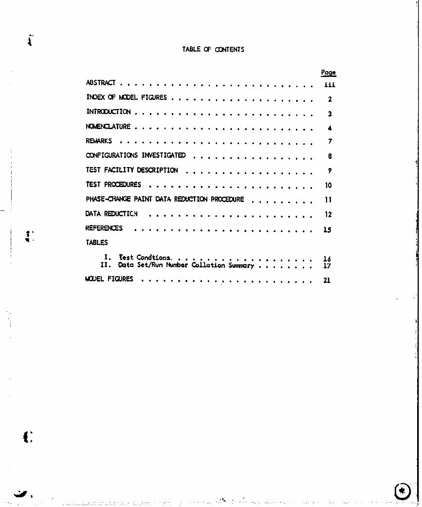
TABLECF O:_WIENTS
ABSTRACT........................... 1££
INDEX OF MODELFIQJRES .................... 2
INT_ION ......................... 3
_TURE ......................... 4
REMARKS ........................... 7
CONFIGURATIONSINVESTIGATED ................. 8
TEST FACILITY DESCRIPTION .................. 9
TEST PROCZ_RE5 ............ ........... 10
PFL_SE-OIN4GEPAINT DATAREDUCTIONPROCEDURE......... 11
I DATA REDUCTICN ....................... 12
REFERENCES ......................... ].5t"
_ TABLES
X. Test Condt£ons. • ...... 16xx. o=_=Set/R_..,,m_e;&iJ.&Zo.__,;, : ....... 17
kl3_L FIGURES ........................ 21
t:
,a,,
1985014157-TSA06

- INDEX OF k_l_ FIGURES
FLgure Pageto. Title No.
.- _mm_mmm
I. Axes Systems Def:lLn:LtJ_n ............... 21
i2. Model Coordinate System ............... 22
3. kiodel Photogrc_s
o. OTS S_le view, post--run No. 20, ......... 23as+5", 8---+5°, P_nt Tea@. 500v
b. OrbLter bottom view, post run No. 22 ....... 24cr-.O°, 8:-5 °, PaLnt Temp. 300°
¢. Tank/SRB t_p vJ.ew, post-run No. 24., ....... 2.1a.--+$o, B=-$o, P(d.'tt Temp. 300°
i
d. OrbLter/Tank - side vLew, post run No. 56 .... 26a_O°, 13--+5° (o_.1 flow)
e. OTS - S_LdqView, post run No_.7 ......... 27azO°, 8=0", Pa_LntTemp. 300v, Math 5.3 . ;
Jit
2
• " 1985014157-TSA07

INTROD{X2TION
An experLmental investigation (IH-42) was conducted to obta£n supersonic
heot-d£str£but_Lon data In areas between the orbiter and external tank using
phase-the, _e paint technqtues. These he=t transfer profiles we _- obtained
Ln order to acquire data that oauld not be obtained using thermocouple in-
strumentation.
Test IH-42 was conducted In the NASA/AmesResearch Center 3.5-foot Hypersonic
Wind Tunnel From April 27 through May 26, 1976. The medal used for this test
was SSV Made1 56-OTS, a O.OI7$-scoIe representation of the orbiter and tar_/
SRB configvra_on 5. Data were obtained for the first and second-stage
ascent configurations a_ U = 5.3 and Re per foot of 5 x 10⁶ which sLmulated4 •
q ascent flight conditions.
Data were recorded at angles-of-attack of zero degree and +_5degrees. This
was the second test tha_ the Rockwell provided phetographic system and data
redu nn program were used a_ the ARC 3.5-foot H_.
All test objectives were successfully met, as well as six additional oil-
Flow vLsuallzatton runs. Thts report contains information on the cancluct
of the testt details of the medel, a summaryo£ the test schedule and con-
ditionst and typical phase-change paint photographs of the model.
3
. )
1985014157-TSA08

Na_EHCLATUREII
Ca._terS_bol
C Specific heat of moclel skL_ material -6TUllh.- °R
Cp, cp Specific heat of aLrstream (perfect gasvol.e) - BTU/Zh.- OR
CHAH QMN Recorc_ng-syst¢_ charmel
dsg c_ees
OF Degrees Fohrerd_eJ.t
ft Foot or feet _,i
How HAW AdJ.abotlcwoZZmthaZpy - BTUIII_ 'iHe HT Preestream to_l enthalpy - BTU/lbm
HwL IN Entha_oy based o_.moclel_,11 tmperatureat LnLt_oZ U_ne BTU/II_n
h H Heat-t_ansfer coeffAcAent at moclelvx_tl" lbm/ft2-se=
hs HS StagnatJ.on-polnt heat-_ans_er coeffLciJntfor refermce sphere IbmlftL-sec
h/hs(X.XXX) H/HS(X.)O0() l_tlo of model heat-transfar coeffLcLentto heat-trmsfer coefficient of referencesphere for Haw/Ht = X._O_
K Thermal.conclucttv£ty
L LB_I Mo_Z refermce length - ft
1bin Pounds mass
M, Id_ IdAQt Frees_ean l_ch number
m Meter(s), un£_ of length
mm I_11_meter(s), un£t of length
Nr Nose radius
PR Prancltl Number
psi. Poundsper square Inch
psLa Absolute pressure in poundsper square JLnch
4
4
1985014157-TSA09

. _TURE (Continued)
- Computer
Pt PT Freestream total pressure psia
_ll Q Iteat-transfer rate at model _Ll at.... in£ttal t_ne - BTU/ft2-sec
_Is QS Stagnatlon-po_nt heat-transfer rate forreference sphere at lnLtLaL t4me
oR Decrees go_k_ne
- Rs RS Reference sphere radius at model scaleequt,vaJ_nt to 0.305 m (1 ft) for fuLl-• scale vehlcle - ft
Re= •RE/IT Freestteam ReynoLds number per foot
Re_e L REL Fremstre_n Reynolds number based an modelreference length, L '_
sec 5eccx_cistunit of tJ;ne
"" T Temperature - OR "
• Tin Initial temperature - OR
Tpc Phase change l_Int temperature
Tt TT Freestrean totc_ temperature - OR
T,_ Twx _.z _u. t=.per°turefo_._v_ T/C ,1_at_on at _n_t_cd. t_ne
• T/C T/C ThermocoW a
t time - sec
t_. TIME Initial tJJne (before model tnsert_on _ntoflow)
Ve VeLocity at edge of bounc_ry layer
I_c_1 angZe of attack, deg
Model angle of s:LdesLlp, deg
u VeLocity
p Density of air
| _ _,,, _n,t.tyof,,od,,!material-z_/fts
' 1985014157-TSA10

_'I'URE {COmeluded)
C._..Outar
p VLscosLty of a/x-lbm-sec/ft2
y Ratio of specific heats ._¢V
Subscripts
aw Ad_obat£c wall
i InLt£ol value beforemodel insertLm Lnto tunnel flow
': PG Perfect gas (caLorLcalZy and themaliy perfect gas)
s ReFerencesphere
t Frees_rea_ total condf._on
. Freestceam
The cooxcLLnatesystemused for thLs test Ls deftrmd by FJ_gureZ. The chfL-nLtLen of the coordLnate system symbolsLs gLven as follows:
b Spant wLngtap to wLng tLpc Chord, wing or vertical taLLL OrbLter lengthx Distance, from nose or Leading edgey B.P. dLstare:e from eenterZJ_ez Water plane cLf.stance,fran reference
plane (FRL@ Z = 400 _nches).OrbLter angular measurement0.0 degbottom_mter L_e
N NozzJ.e0 OrbLter reference systemV VertLcaltall referencesystemET External tank reference systemXS 5o1£d rocket motors reference system
1985014157-TSA11

REMARKS
The £nstallation of Model 56-0TS began on April 26, [976. The first run
was attempted art the night of April 27, 1776. However, during this run
a severe vibration was observed. This vibration was due prlmar£1y to the
3 + G's of insertion dmce!eration and normal runn£ng loads.
The orbiter-tank attach structures (approxLmQtely 50 percmnt of the forward
and aft protuberances) and the aft SRS-tonk attach structures were blown
off a_d destroyed. The severe shaking of the orbctor e tank, and _B's
crushed and fractured f_sa parts which, like t_a rest of _he mod_, were
made from Nova_Lde. The damagedNovamCdeprotuberances were replaced w¢th
stainless steel and the model support harc_re was braced to m_n_Lze model41 •
• dynamics.
A ¢_bined total of 57 runs were mode in approxcmately 218 occupancy hours.
Two out of the 5"7runs were repeats, altheugh all runs yielded valid data.
7
1985014157-TSA12

CI3NFIGURATI_ INVESTIC.JdED
The model used during rest XH-42 wos a O.Ol75-scole repllca of the Sooce
Shuttie Lntegrated vehicle-§ confLguration, designated UodaZ 56-0TS.
Tnis model is a phase-change paint modei and is described by the VC70-000002i
configuration control c_awings mocLtfied In July 1975 for support of Test
IH-42. The external tank (spike-nosed) was buJtt to VC78-OOOOO2Dlines#
• and the solid rocket boosters were built to VC77-OOOOO2FLines.
; The orbiter model was orig_ally fabricated by Lockheed AuLrcraft C_pany
and was cast in one piece fran their proprietary material "U'I'.
:i external tank and 1he SPB's were cast in single pieces _round a steel sting
using Novomtde 700-55 ma_eriol and machined to contour. Three complete
,: model ossembl].es were available for this test: Model 56-0TS-1 (o paint-
stripe model), ond I_dels 56-0TS-2 and 56-0TS-3 (test mo_!s).
i.
8
1985014157-TSA13

/
LTEST FN:ILITY DESCRIPTIOrl
The NASA/Ames 3.5-foot Hypersonic Wind Tunnel is a closed-circuit blo.-
do-n-type tunnel capable of operating at nominai _k_chnunbers of 5, 7,
and 10 at pressures to 1800 psia and temperatures to 34000R for run times
to four minutes. The major components of the facility include a gus
storage syste_n where the test gas is stored at 3000 psi, a storage _oter
filled with aluminum-oxide pebbles capable of heating the test gas to
3400OR, axis)mnmetric contoured _ozzles with exit diameters of 42 _ches
for generating the desired Wach number, and a 900,000 f_3 wc_um ._"_rQg,.
system which operates to pressures of 0.3 psia. The test seci!'_, : ._eJ.f" i_
an open-Jet type enclosed within a chamber" oporor;_n _.c_y 12-.fact _n ai,_..L-.r
and 40-feet in length, arranged transver._,,1/ to the flow directior'.
" A model support system is provided that ca_ pitch models thro_:_jh on _nule-
of-attack range of -20 to +18 degrees, in a vertical plane, abo_ a fixed
pg.C.ntof rotation on the tunnel centerline. This rotation point is adjustable
i from 1 to 5 feet from the nozzle exit plane. The model no.-molly ts out of
the test stream (strut centerline 37-bnches fro_ tunnel centerline) until
the tunnel test conditions ate established after which it is inserted.
Insertion time is adjustable to as little as 1/2 second _nd modeZs may be
inserted at any strut angle.
............. ............ _ , _ .
1985014157-TSA14

TEST PROCEDURES
The 56-0TS model was mounted, at vorious a and B comb_a+.J.ms, to the
tunnel quLck-Lnsert support mechon:Lsm. Th:[s mechons:Lmin_Jected the model
into the aLrstreom when study-state test condLt£ms hod been established,
and retrocted the ,,_¢K:lelat the completion of data recorcLf.ng. The model
injection tLme, tLme on tunnel ¢enterlJ_e, and retraction time were setI
to ojLve a total exposure time of approx_ateZy Five secandse of which
three seconds were an tunneZ centerl_ne. The 56-0T5 IdodeZ (with protuberances)
was used to cbtaLn Orbiter ascent aerodynamic heating rates, uttltz.tng
_ phase-change point technLcives to determine Lsotherms of" melt ZLnes for
different temperatures. The type of" paint used fer this test was Tempelac._)
paint. The specific paint meZt temperatures used were 250, 300w 350w 400,
450, 500, and 550°F. However, the majority of the test was can_cted using
pa_a_t melt ten,peratures of 300 end 400o1:.
Before the test_g begant photographs of the grid model w_re token for each
attitude to be investigated. The modeZ was then mounted in the test section
and pointed with the al_copriate phase-change paint. The test sectian was
closed and the wind tunneZ started with the model out of the aLrstream. The
model's LnLtLal temperature was recccded and the mocbl was inserted Into
the aCrstream. After each run was canpleted, the model was retracted and
s_oarated, and the melt Z_nes between the orbiter and external tank were
photographed. The model was then washed with soZvent and repainted for the
next run,
Figures 3a through 3e are photographs of the Model 56-OTS lnstallatim in
the NASA/ARC3.5-ft HWT. These photographs ore ty_Lcal of post run condl-
tions showing the phase-change paint melt lines and the oil-Flow character-
¢stics for each configurat_Lon.
• IO
J_ .... ...... -_, _-._. .......... ......... . ..... . ........... ............... .......
• , r. _......
1985014157-TSB01

PHASE_E PAINT DATAR_-_CTION PROCEDURE
A special program ,as develq3ed fox" use in conJunctian with the photographic
lnsttumentat_an to autamat_cally reduce heating rate data. The three 35ram
cameras ,ere synchronized with the time the model came to centerline. The
resulting date output l_ked the tunnel h/h reference with the lsothem
l_es vislb[e on each photographic frame taken. This program was used on
_ the ARC IBk_-360 facJ.IJ.ty ¢amputer.
' ThLs data reductLon procedure *as developed For use In the NASA/ARC3.5-f`t
HWTf`ot Test IH-42, as well as the orbLter phase-change paint Test OH-$3B.
._ However, after the Initial run to obtaLn the heat transfer paint melt lines
* _n the medel lnterstage oceo f`_r Test IH-42, It became obvious thet the
, cameras could not adequately photograph the areas oF Interest to yield
_- def`init_ve data. Theref`ore, the model cam_ents were se_orated af'tet each
_i run and photographs of" the melt l_es were taken. It should olso be notedL
that the outcmotlc date reduction was used only f`or the last clara poLnt
.... bef`cce model retract/on to Indicate the heat ttonster coef'Ftcrent.
i
1985014157-TSB02

DATA REDt_'TION
At1 test data were reduced at the NASA/ARCusing the data reduction
technique outlined beJ.ow:
PhaseChangePaint Data Reduction
The aerodynamicheat transfer caeFfic:l.ent was calcuZated as _utlined below
Par each motion picture frame.
4
_1- h(Haw-Hw)-----hHt " Ht;" h Cp (Taw_- Tw)/
• .re. Ht =Cp Tx e-(Z_._l.1 Tie
e corrects For therm_l.ly pe_fect_ calorically impeFfect atx.
e Is caZculated as a Function of Tt using _ polynantal curve Pit.
(r®ITt)nwhere: e ---(T®/TtJPG >. 1
I"PG- Thema].ty I_rf_t gos
PG- _lorlcally and the.,'nmlly perfect
"t c.+ Ht
Haw 1.0, 0.9 ar .85 (NOTE:_I :l.s Independent of"
: the Haw/Ht used for both h and Clevaluations).
Hw Tpc/ Tt_'t=_
12
h
• " 1985014157-TSB03

DATA RE_JCTXON (Continued)
Assuming a semi-Infinite slab solution, _ Is calculated from
low' lin
' 13Is then detez_nlned using _ and Iterat_mg
2
1 - _ = • B (1 - err 13)
The hea_ t.ransfer coeffAcJ.emt As then derAved by so].ving: _,1
h= q_- ep I _,
where:
Z
using h,
To determJale h o_ Haw/Ht = 0.9 and 0.85
the _ue of cl _or Haw/Ht = 1.0 was
used Ln the £oJ.lowing:
,
13
1985014157-TS B04

- DATAREDUCTION(Concluded)
For h/h s comparison, the value of hs, the stognat_on heat transfer coefficient.
was determ:Lned as Follows:
• qs = hs (Ht " Hw)
h =o.;,68(p -o.6) (_, _,).1(_,_,).4d_-I _
ax IS_ t ( 1 - Ps
P=/Ps = P= / Pt
I _(Pt2/Ptl ) TF_
PSRCcorrects for thermIJ.ly perfect aLL" _ was obtaJ.ned ,• r
" from a polyna.:Lal curve fit us:Lng Tt.
Perfec_t
P®/Pt, . P,_I " PRC where PRC--(P=/P_) TPG
pt I 0)= / Pt) P'GPerfect
(PRG ¢o_mcts for tl_rmolly perfect, air and.is alsoderJ,ved us_g a polync_Lal curve ,_lt of Tt.)
Perfect
_- 14w
t
"I9850"I4"I57--I-GB05
REFERENCES
1. "Pretest InformatLon for Testing the O.0175-Scale Phase C_ange PaLnt
Model 56-0TS in the ARC3.5-ft Hypersonic Wind Tunnel Test IH-42"
(January 27, 1976)
15
1985014157-TS B06

Ta hie ]]
TEST : 7. H-','2- ] DATE *. 5"-26- 76
TESTCDNDITIONS
.5"._J ,405 1"50o 5".00 x !0 6i i
i :
i
BALANCEUTILIZE[}: N A
COEFFICI£NTCAPACITY: ACCURACY: TOLERANCE:
_IF ..
SF
AF
PM _ _.__
RM ...............
YM
COM_[NT_:
16
1985014157-TSB07


,, )
.... 1985014157-TSB09

,,t,'r
i
1985014157-TSB10

, .;)
" ,j
1985014157-TSB11

U
zl
_!
1985014157-TSB12

1985014157-TSB13

ORIGH,:At_ P/',(;_,= :'_
O1:' POOR Q_.JALIT_
It
ii
e,
tI
23
1985014157-TSB14

O_C_rAL |-q:,'_F,_,OF POORQUALITY
24
P
1985014157-TSC01

0
1985014157-TSC02

F
1985014157-TSC03

1985014157-TSC04