.L::IVEIOEIIV )4OV.LLV/I:I:I.LHOh:! /SOO · Design of a Low Cost Short Takeoff-Vertical Landing...
91
7LIbT-O6N 310 13S0 {'^!Ull ujnonv ) <_ t/-. I dv t-,9_-_I V >I3_a I IV/* _ 1 t_'71 ") C,_.Ia>_V-I 2VD!I_= ^-:::': ._,, i q __r _P.s_gLa 1-'_j9-v avN ) 066 _ eunl" etueqelV '_i!SJeA!UI'I uJnqnv X_,!SJOA!UlquJnqnv •tueJ6OJd u6!seG peoueAPV _;!sJe^!ulq VhlSANSVN eql _o d!qsJosuods eql Jepun _l!sJe^!uf'l umqnv le 6u!jeeu!6u=J eoedsoJev ;o luetulaedec] eq; u! s;uepnls aq loe[oJd u0!sep V .L::IVEIOEIIV )4OV.LLV/I:I:I.LHOh:! .I-I:lOdX=l ,D NIC!NV-i-'IVOI.LI:13 A'=I-I O3)IV-L'-LI:IOHS /SOO _O'1 V 40 N_DIS=J(3 i https://ntrs.nasa.gov/search.jsp?R=19900015816 2019-08-29T02:47:30+00:00Z
Transcript of .L::IVEIOEIIV )4OV.LLV/I:I:I.LHOh:! /SOO · Design of a Low Cost Short Takeoff-Vertical Landing...

7LIbT-O6N
310 13S0{'^!Ull ujnonv )
<_ t/-.
I dv t-,9_-_I V >I3_a I IV/* _ 1 t_'71 ")
C,_.Ia>_V-I 2VD!I_= ^-:::':._,,iq __r _P.s_gLa 1-'_j9-v avN )
066 _ eunl"
etueqelV '_i!SJeA!UI'I uJnqnv
X_,!SJOA!UlquJnqnv
•tueJ6OJd u6!seG peoueAPV _;!sJe^!ulq VhlSANSVN
eql _o d!qsJosuods eql Jepun _l!sJe^!uf'l umqnv le 6u!jeeu!6u=J
eoedsoJev ;o luetulaedec] eq; u! s;uepnls aq loe[oJd u0!sep V
.L::IVEIOEIIV )4OV.LLV/I:I:I.LHOh:! .I-I:lOdX=l,DNIC!NV-i-'IVOI.LI:13 A'=I-I O3)IV-L'-LI:IOHS
/SOO _O'1 V 40 N_DIS=J(3
i
https://ntrs.nasa.gov/search.jsp?R=19900015816 2019-08-29T02:47:30+00:00Z

Design of a Low Cost ShortTakeoff-Vertical Landing
Export Fighter/Attack Aircraft
Designers 'Anne BelcherDan Bodeker I I ISteve MiuLaura PetroCary Taylor SenfDonald Woeltjen
Advisor •J. o. Nichols

DESIGN OF A LOW COST
SHO RT.TAKEOFF-VERTICAL LANDING
EXPORT FIGHTER/ATTACK AIRCRAFT
AUBURN UNIVERSITY
Abstract
This report presents the design of a supersonic short takeoff and
vertical landing (STOV'L) aircraftthat is suitable for export. An
advanced four poster, low bypass turbofan engine is to be used for
propulsion. Preliminary aerodynamic analysis is presented covering
a determination of CD versus CL, CD versus Mach number, as well as
best cruise Mach number and altitude. Component locations are
presented and center of gravity determined. Cost minimization is
achieved through the use of developed subsystems and standard
fabrication techniques using nonexotic materials. Conclusions
regarding the viability of the STOV'L design are presented.

Table of Contents
Section Number
Io
2.
3.
4.
4.1
4.2
4.3
4.4
5.
5.1
5.2
5.3
5.4
6.
7.
8.
9.
9.1
9.2
9.3
Section
Abstract
List of Figures
List of Tables
Introduction
Statement of the Problem
Requirements
Technical Information and Configuration
Initial Sizing
Mission Weights
Component Weights
Center of Gravity Deter minations
Geometry
Wing Geometry
Horizontal Tail Geometry
Vertical Tail Geometry
Control Surface Sizing
Rubber Engine Sizing
Landing Gear
Weapons System
Special Considerations
Hydraulics
Avionics
Crew Station
Page
I
IV
VI
3
6
9
14
14
19
2O
22
23
23
25
26
27
3O
32
34
37
37
38
39
II
Table of Contents (continued)
Section Number
9.4
9.5
I0.
II.
II.I
11.2
11.3
11.4
12.
13.
14.
Section
Materials
On Board O_gen Generating System
Survivability
Performance
Airfoil
Drag Polar
Drag Versus Mach Number
Drag Coefficient Versus Mach Number
Cost Analysis
Discussion
Conclusion
Bibliography
Appendix A
Appendix B
Page
44
46
47
51
51
52
55
56
57
60
63
64
66
69
,III

List of Figures
Figure Number
3.1
3.2
4.1.1
4.1.2
4.1.3
4.3.1
5.1.1
5.2.1
5.3.1
5.4.1
5.4.2
5.4.3
7.1
8.1
9.1.1
9.2.1
9.3.1
9.3,2
9.3.3
9.3.4
9.3.5
11.1.1
I 1.2.1A
Figure Title
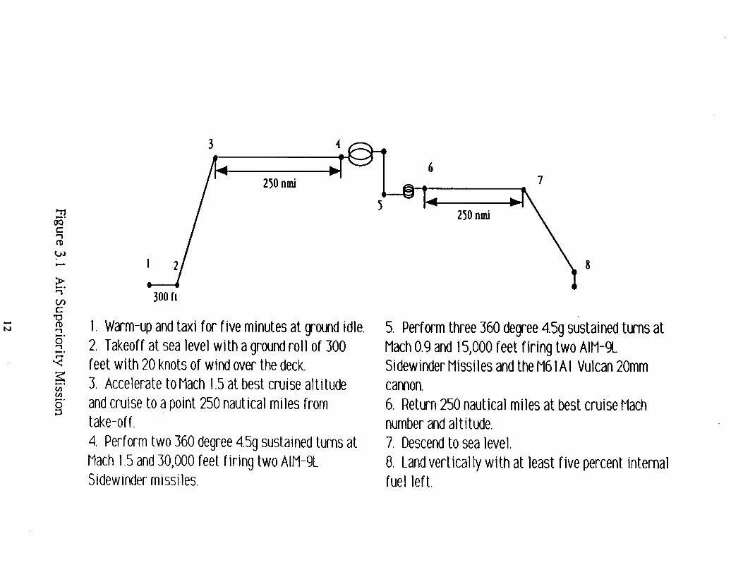
Air Superiority Mission
Ground Superiority Mission
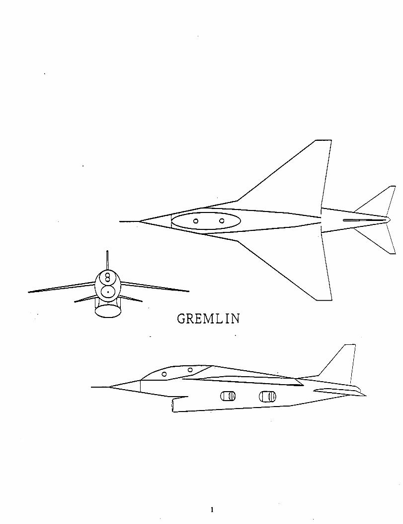
Gremlin Front View
Gremlin Side View
Gremlin Top View
Weight Distribution
Wing Geometry
Horizontal Tail Geometry
Vertical Tail Geometry
Ailerons
Elevators
Rudder
Gremlin Landing Gear
M61 Vulcan Gun
Simplified Hydraulic System
Aviordcs Block Diagram
Crew Station Geometry
Pilot Visibility
Pilot's View of Control Panel
Explanation of Control Panel
Nozzle Vector Control and Throttle
Airfoil
Drag Polars Subsonic
Page
12
13
16
17
18
2O
24
25
26
28
29
29
33
36
37
38
40
40
41
42
43
51
53
IV

List of Figures (continued)
Figure Number
11.2. IB
11.3.1
11.4.1
Figure Title
Drag Polars Supersonic
Drag Versus Mach Number
Best Cruise Mach Number
Page
54
55
56
V
List of Tables
Table Number
4.2
4.3.1
4.3.2
6.1
12.1 .
Table Title
Mission Weights
Weight Determination
Weight Distribution
Engine Parameters
Cost Analysis
Page
19
20
21
31
59
VI
0 0
GREMLIN
00
@ Q

I. Introduction
In the first few hours of a future war, most military fortifications will
be attacked by nuclear, chemical or extremely accurate conventional
weapons. Airbases, with their command, communications and control
centers as well as airstrips for aircraft operations, will be prime targets.
Because of this accepted fact, NATO has adopted a doctrine of aircraft
dispersal whereby fighter and light attack aircraft are dispersed to
smaller airfields as well as civilian highways and country roads in order
to create more targets as well as to confuse the enemy. This strategy in
itself creates problems because the smaller airfields are probably already
secondary targets. When considering these as well as other problems, the
advantages of STOVL fighter/attack aircraft become obvious. Unpaved
fields or parking lots could become instantaneous bases. Considerable
expense could be avoided and tactical advantage could be achieved all at
the same time. Also, as conditions dictate,
the STOVL aircraft could be redeployed rapidly in order to take advan-
tage of changing tactical conditions.
The British Aerospace/McDonnell Douglas Harrier Fighter/Recon./Strike
aircraft is presently in the U.S. Marine Corps inventory. It is the only
operational STOVL aircraft flying with the U.S. military but is also capable
of V/STOL (vertical/short takeoff and landing). The Harrier I first entered
British service in 1965 and entered U.S.M.C. service in 197 I. Through
constant redesign and improvement of propulsion, avionics and lifting
surfaces, a variant, the AV-8B Harrier If, resulted. This aircraft distin-
guished itself during the British/Argentine Falkland Island conflict in
1982. Because of its extreme agility in air combat, not a single British

Harrier was lost in air combat (although nine were lost to ground fire).
However, a major disadvantage of the Harrier I and II aircraft is its ina-
bility to go supersonic in cruise flight. Any fighter/attack aircraft of the
future will be required to sustain a Mach number much greater than one
for several reasons. The need to fly to the target quickly (low response
time) is a must. Also, the faster an aircraft flies, the smaller amount of
time is spent above hostile ground fire. Another point is that even though
dogfights between combat fighter aircraft usually occurs in the transonic
regime or slower, a supersonic aircraft would have an advantage because
of the increased power available as well as potential acceleration as op-
posed to a purely transonic aircraft such as the Harrier.
In response to the need for a supersonic STOVL aircraft, AIAA has
sponsored a request for proposals (RFP) for an aircraft meeting the above
criteria as well as many others. This aircraft was required to be designed
as a short takeoff or vertical landing low cost export fighter. This design
proposal will pose a unique set of challenges. ]Because of the weight mini-
mization
needed for the vertical aspect of flight (thrust=weight) lightweight, and
oftentimes exotic materials, will be needed for the construction of this
aircraft. A new generation of vectored thrust engines will have to be
developed since there are no jet engines on the market at the present
time capable of producing the performance needed for this aircraft.
Since the cost of an aircraft is a function of the amount of new tech-
nology that is involved in its development and construction, it is obvious
that it will be a major challenge to keep cost within the range of "low
cost". Since the low cost ST0VL fighter/attack aircraft (dubbed 'Gremlin')
will have a multirole capability, this aircraft could be sold to European as

well as friendly third world allies for their air defense needs. The STOVL
capability of this aircraft would be a great advantage to lesser developed
countries. Fixed airbases are expensive to construct, maintain, and defend;
therefore an aircraft that can takeoff and land in an undeveloped area
would be much more cost effective as well as tactically effective.
One way to reduce cost in aircraft development is to rely heavily on
developed systems. Also, since tomorrow's aircraft will rely much more
on costly electronics, an easy way to contain costs is to place only the bare
necessities in the way of avionics in the aircraft. Many times avionics are
designed for every possible combat theater. This increases cost and com-
plexity. By designing theater specific avionics packages (i.e. European
theater would be much different than African or Middle East theater etc.)
and installing each during final assembly and delivery to the customer,
the extremely high avionics cost could be reduced.
The fabrication and construction of this aircraft will rely heavily on
subcontracting. Existing systems, when permissible, will be used to avoid
development and associated cost. The air frame assembly will be under-
taken by the main contractor and subsequent subsystems will be installed
with subcontractor support.
5
2. Statement of the Problem
!
In 1982 the need for V/STOL was proven in the Falkland Islands.
England relied heavily on the Harrier, a V/STOL aircraft, for its air combat
and air-to-ground strikes. The response time, maneuverability, and abil-
ity to land in a small area were great advantages the Harrier possessed
over conventional aircraft. Harriers were attributed with downing 28
Argentinian aircraft, while no Harriers were shot down by Argentinian
aircraft.
The destruction caused by nuclear and conventional weapons must be
a major consideration in a conflict. NATO and American military airfields
as well as aircraft carriers are primary targets. To prudently prepare for
this loss, aircraft are needed that are capable of landing in a small area.
Often in a combat situation, pilots will takeoff for a mission, then return to
find their base or aircraft carrier has been destroyed. They then will be
forced to land on a damaged runway, a road, a forest clearing, a small
naval vessel, or a cargo ship. This capability is found in a STOVL aircraft.
A large market currently exists for a low-cost STOVL fighter/bomber
since it will be a high technology aircraft at a comparatively low price.
The airplane will primarily be designed as an export for less developed
countries. It will be a multi-purpose aircraft capable of air combat and
air-to-ground strikes which makes it a desirable asset to any country's
armed forces. Its supersonic speed, high degree of maneuverability, and
vertical landing capabilities will give it advantages over conventional
aircraft. The low cost will make the STOVL aircraft available to third
world countries. Also, it will be useful as a trainer to more developed
countries who wish to train their pilots for higher technology aircraft.
6
Another possible market will be military aerobatic teams since the STOVL
aircraft will have aerobatic capabilities which conventional aircraft do not
possess.
One V/STOL aircraft is in use by American and British military forces
today, the Harrier or AV-8B. The Harrier not only has STOVL capabilities,
but also has vertical takeoff capabilities. The Harrier was developed by
British Aerospace and in recent years, vastly upgraded by McDonnell
Douglas. The Harriet's top speed is Mach 0.93 which limits its perform-
ance against faster enemy jets and for long range missions. The Soviets
have developed a supersonic VTOL (vertical takeoff or landing) fighter/
bomber, the Yak-36 Forger which is capable of flying at Mach 1.2. No
strictly STOVL aircraft has yet been developed.
The prototype to the Harrier, the Hawker P. I 127 first appeared in
1960. It was the first vertical takeoff and landing aircraft developed. The
latest American version of the Harrier is the AV-8B which replaces the
AV-8A. Currently, four navies employ the Harrier-United States, Royal,
Spanish, and Indian. In the United States, the Marines use the AV-8B
since it fits their needs both in the field and at sea. It is capable of re-
sponding in eight to ten minutes and landing in a small area. Although the
Harrier is capable of vertical takeoff, it usually takes-off with a short taxi
enabling it to increase its payload and range.
The Rolls-Royce Pegasus turbofan engine is utilized to power the
Harrier by exhausting the cold stream through two front nozzles and the
hot stream through two rear nozzles. The nozzles are capable of rotating
through greater than 90 degrees. They are pointed down and slightly
back for takeoff, then rotated aft for cruise. The Harrier possesses a jet
reaction control system which consists of a puffer at the nose, tail, and at
7
each wing tip. The reaction control jets are used for control during takeoff
and landing. The United States Marine Corp added an option to the Har-
rier, VIFF (vectoring in forward flight). By rotating the nozzles during
combat, vectored aircraft have significant advantages during dogfights.
They are capable of many more maneuvers than conventional aircraft.
The USSR's vectored thrust aircraft, the Yak-36 Forger, is much less
sophisticated than the Harrier. It is strictly a vertical takeoff aircraft
without the short takeoff capability of the Harrier. This fact limits its
maximum payload to approximately one-fourth of the Harrier's payload.
The Forger utilizes two engines forward of the center of gravity strictly
for lift and one engine at the rear for lift and cruise. The main engine
located in the rear is an unreheated turbojet engine. Like the Harrier, the
Forger has puffer jets at the wing tips to control yaw and roll. To control
the pitch, the Forger depends on selective throttling by the engine. It does
not possess VIFF capabilities. Although takeoff and landing are com-
pletely computer controlled, the change between vertical and horizontal
flight is a slow process in comparison to the Harrier. A large amount of
fuel is burned during the transfer.
8

3. Requirements
The Gremlin was designed as a multi-role, lightweight, high thrust
to weight ratio aircraft with a top speed of Mach 1.5. It has a high instan-
taneous turn rate provided by its main and trim thrusters. The avionics
used in the aircraft were chosen for their reliability and ease of mainte-
nance since the aircraft will be exported to third world countries. Since a
basic radar is considered essential in a supersonic military aircraft, the
Gremlin employs a reliable system which is capable of performing in
either and air superiority or ground support role. The capabilities of the
Gremlin in the air superiority mission are demonstrated in Figure 3. I and
the capabilities in the air-ground mission are demonstrated in Figure 3.2.
The aircraft also meets the following requirements carrying a full
weapons load with sixty percent of internal fuel:
I. Accelerate from Mach 0.9 to 1.5 at 30,000 feet in less than sixty
seconds.
2. Have specific excess rate of climb powers of:
a. 750 feet per second at I0,000 feet and Mach 0.8.
b. 500 feet per second at 30,000 feet and Mach 0.8.
The wing of the Gremlin is able to meet the following criteria:
I. Sized to generate a 9.0g load factor at combat load and speed.
2. Capable of performing a wing-lift only landing in a rare event fail-
ure of the vectoring drive. The aircraft will be able to meet the following
specifications during such an emergency landing:
a. No more than a 140 knot touchdown speed.
.
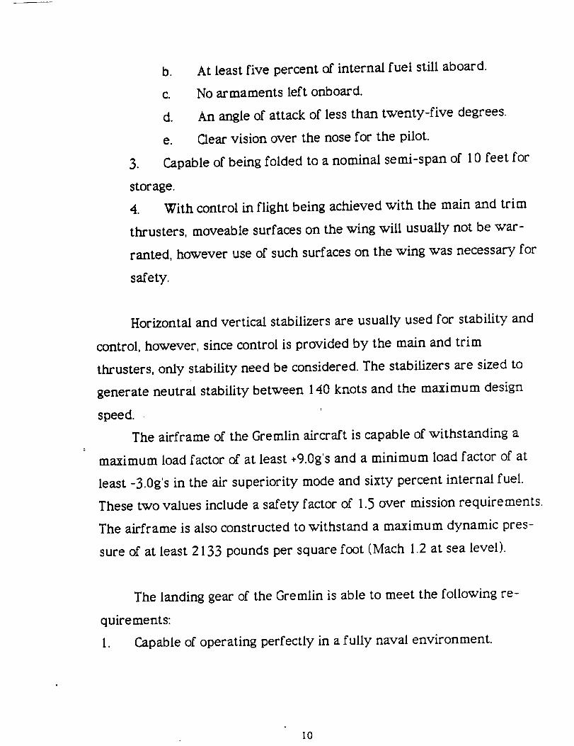
b. At least five percent of internal fuel still aboard.
c. No armaments left onboard.
d. An angle of attack of less than twenty-five degrees.
e. Clear vision over the nose for the pilot.
Capable of being folded to a nominal semi-span of I 0 feet for
storage.
4. With control in flight being achieved with the main and trim
thrusters, moveable surfaces on the wing will usually not be war-
ranted, however use of such surfaces on the wing was necessary for
safety.
Horizontal and vertical stabilizers are usually used for stability and
control, however, since control is provided by the main and trim
thrusters, only stability need be considered. The stabilizers are sized to
generate neutral stability between 140 knots and the maximum design
speed.
The airframe of the Gremlin aircraft is capable of withstanding a
maximum load factor of at least +9.0g's and a minimum load factor of at
least -3.0g's in the air superiority mode and sixty percent internal fuel.
These two values include a safety factor of 1.5 over mission requirements.
The airframe is also constructed to withstand a maximum dynamic pres-
sure of at least 2133 pounds per square foot (Mach 1.2 at sea level).
The landing gear of the Gremlin is able to meet the following re-
quirements:
I. Capable of operating perfectly in a fully naval environment.
I0
2. Capable of withstanding a vertical speed of twenty feet per second
when the aircraft is making a vertical landing.
3. Capable of withstanding a routine landing at sixty knots and a verti-
cal speed of fifteen feet per second.
4. Capable of withstanding an emergency landing at 140 knots and a
vertical speed of I 0 feet per second.
II
I,.ii_ o
t-
IIA
I,I.
ri I
"O
"1Ii.,,,, •
O
I,,i,_ 6
l, iii. o
O
3
300 ft
250nmi
250nmi
8
1. Warm-upandtaxi for five minutesat groundidle.
2. Takeoffat sealevelwith a groundroll of 300feet with 20 knotsof wind overthedeck.
3. AcceleratetoMach1.5at best cruisealtitude
andcruise to a point 250nauticalmiles fromtake-off.
4. Performtwo 360degree4.5gsustainedturnsat
Mach1.5and30,000feet firing two AIM-9LSidewindermissiles.
5. Performthree360degree4.5gsustainedturnsatMach0.9and15,000feet firing two AIM-gLSidewinderMissilesandtheM61A1Vulcan20mmcannon.
6. Return250nauticalmiles at bestcruiseMachnumberandalt itude.
7. Descendto sealevel.
8. Landvertically with at least five percentinternalfuel left.

ji,,I.
ka
C1
O
rj_f-
ebi-Iii.,i.°
O
Ii,_°
q
c_I,I,IA.
O
3 4 8 9
2 boardG" InboardG"
v
50nmi 5 50nmi
I0
I. Warm-upandtaxi for five minutes at groundidle.2. Takeoff at sealevel with a groundroll of 300feet with 20 knotsof wind over the deck.
3. Accelerateandclimb to best cruise Machnumberandaltitude for outboardcruise.
4. Descendto 250 feet andpenetrate50 nauticalmiles at Mach0.8.
5. Drop6 Mk82500 poundbombs.
6.Performthree360degree6.5gsustainedturnsat
Math0.8andsealevelfiringtheM6IAIVulcan20ramcannon.
7.Egressat250feetfor50nauticalmilesatMach0.8.
8.ClimbandreturntobestcruiseMachnumberandaltitude.
9.Descendtosealevel.
10.Landverticallywithatleastfivepercentinternal fuelleft.
4.1
4. Technical Information and Configuration
Initial Sizing
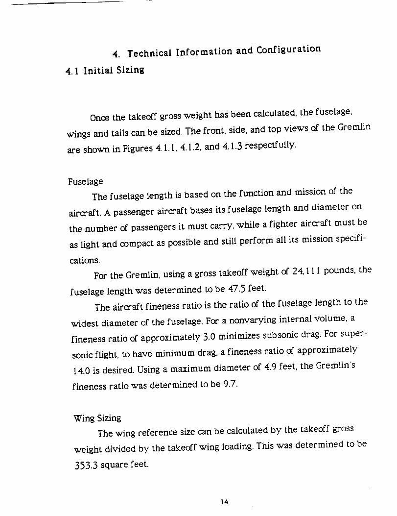
Once the takeoff gross weight has been calculated, the fuselage,
wings and tails can be sized. The front, side, and top views of the Gremlin
are shown in Figures 4. I. I, 4. 1.2, and 4. 1.3 respectfully.
Fuselage
The fuselage length is based on the function and mission of the
aircraft. A passenger aircraft bases its fuselage length and diameter on
the number of passengers it must carry, while a fighter aircraft must be
as light and compact as possible and still perform all its mission specifi-
cations.
For the Gremlin, using a gross takeoff weight of 24, I 11 pounds, the
fuselage length was determined to be 47.5 feet.
The aircraft fineness ratio is the ratio of the fuselage length to the
widest diameter of the fuselage. For a nonvarying internal volume, a
fineness ratio of approximately 3.0 minimizes subsonic drag. For super-
sonic flight, to have minimum drag, a fineness ratio of approximately
14.0 is desired. Using a maximum diameter of 4.9 feet, the Gremlin's
fineness ratio was determined to be 9.7.
Wing Sizing
The wing reference size can be calculated by the takeoff gross
weight divided by the takeoff wing loading. This was determined to be
353.3 square feet.
14

Tail Sizing
A historical approach is used during the determination of tail siz-
ing. The main purpose of the tail is to counteract the adverse moments
that are generated by the wing. Therefore, the greater the distance from
the aerodynamic center of the tail to the aerodynamic center of the wing,
the smaller the tail area must be. The moment arm of the tail can be de-
termined by historical data which for a mid-mounted engine is 45-50
percent of the fuselage length. Using 48 percent of the fuselage length,
the moment arm of the tail was calculated to be 22.8 feet.
The horizontal tail area, Sht, was calculated to be 68.2 square feet.
The vertical tail area, Sv_,was calculated to be 33.6 square feet. Because
of the effect of rotatable nozzles, some of the stability that the tail pro-
vides can be provided by the thrust. Therefore, the horizontal tail area is
reduced by 15 percent which gives us a new horizontal tail area of 57.97
square feet.
15

f 31 ft
_-- 5 ft---_
Figure 4. I. I Gremlin Front View
16

48 I't
22 ft
t3 ft
Figure 4. 1.2 Gremlin Side View
17
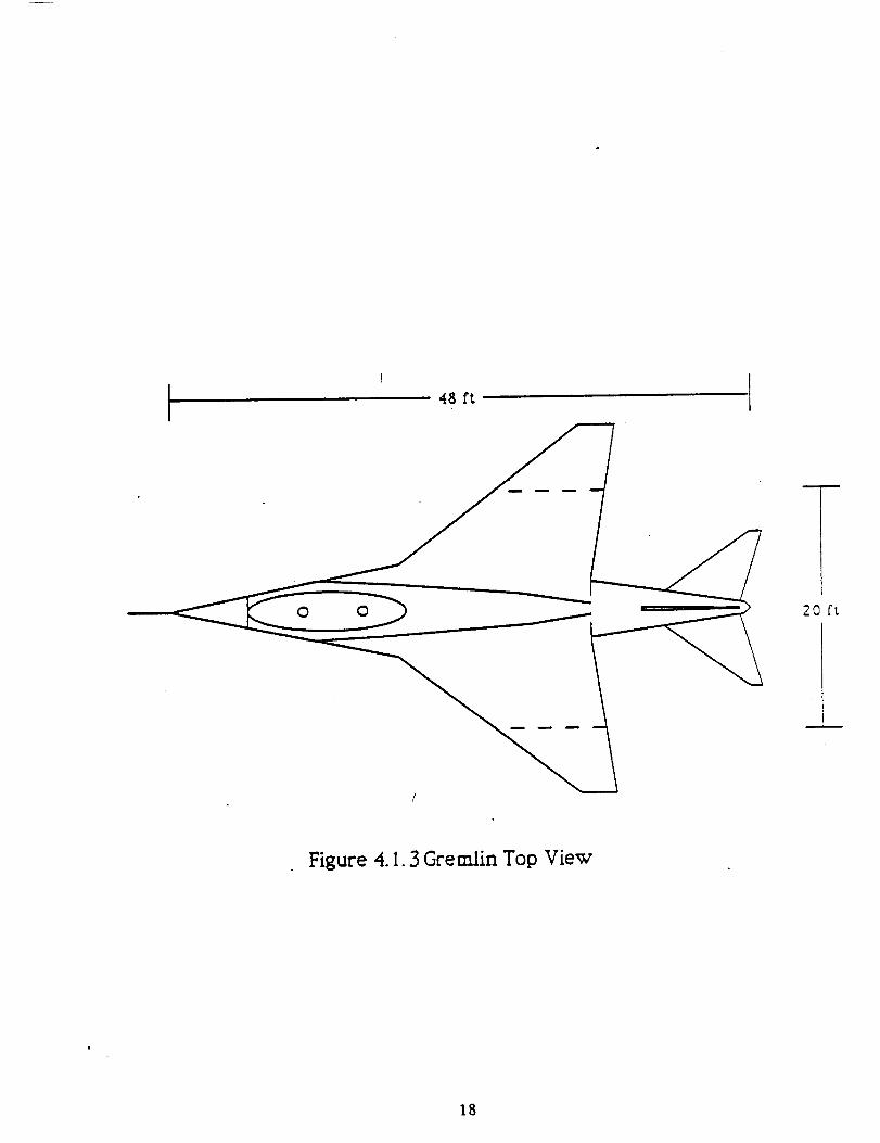
48 ft
0 0 20 ft
Figure 4. I. 3 Gremlin Top View
18
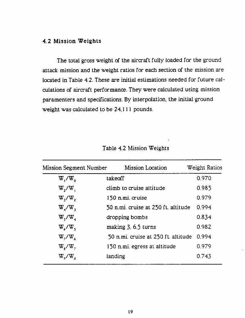
4,2 Mission Weights
The total gross weight of the aircraft fully loaded for the ground
attack mission and the weight ratios for each section of the mission are
located in Table 4.2. These are initial estimations needed for future cal-
culations of aircraft performance. They were calculated using mission
paramenters and specifications. By interpolation, the initial ground
weight was calculated to be 24, I I 1 pounds.
Table 4.2 Mission Weights
Mission Segment Number Mission Location Weight Ratios
W I/W 0 takeoff 0.970
W2/W _ climb to cruise altitude 0.985
W3/W z 150 n.mi. cruise 0.979
W4/W 3 50 n.mi. cruise at 250 ft. altitude 0.994
Ws/W 4 dropping bombs 0.834
W_/W 5 making 3, 6.5 turns 0.982
W_/W_ 50 n.mi. cruise at 250 ft. altitude 0.994
Ws/W 7 150 n.mi. egress at altitude 0.979
Wg/W 0 landing 0.743
19
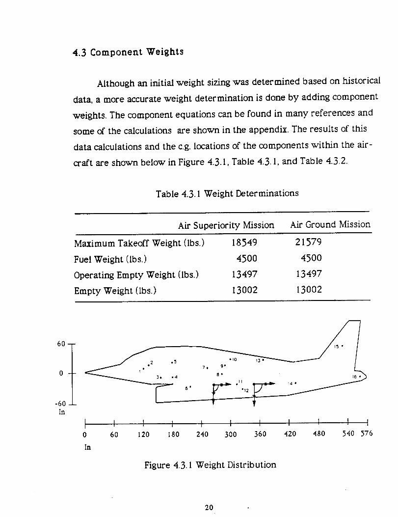
4.3 Component Weights
Although an initial weight sizing was determined based on historical
data, a more accurate weight determination is done by adding component
weights. The component equations can be found in many references and
some of the calculations are shown in the appendix. The results of this
data calculations and the c.g. locations of the components within the air-
craft are shown below in Figure 4.3. I, Table 4.3. I, and Table 4.3.2.
Table 4.3. I Weight Determinations
Air Superiority Mission Air Ground Mission
Maximum Takeoff Weight (Ibs.)
Fuel Weight (Ibs.)
Operating Empty Weight (Ibs.)
Empty Weight (Ibs.)
18549 21579
45OO 45OO
13497 13497
13002 13002
-60 -
In
I I I I I I I I I I I0 60 120 180 240 300 360 420 480 540 576
In
Figure 4.3. I Weight Distribution
2O

Table 4.3.2 Weight Distribution
Component Location Weight
From Figure (Ibs.)
Fuselage Center Line WaterlineStation (in.) Station (in.} Station (in.}
Wing 13 2086Horizontal Tail 16 298Vertical Tail 15 470
Fuselage 8 1351Main Landing Gear 12 766Wing Landing Gear 13 206Engine Mounts I I 41Firewall 11 28Engine Section 11 20Air Induction 6 418
Engine Cooling I 1 256Oil Cooling 11 38Engine Controls 2 5Starter 11 53Fuel System & Tanks I0 698Flight Controls 2 490Instruments 2 212
Hydraulics 9 172Electrical 9 681
Avionics 4 1457Furnishings 2 435AIC & Anti-lce 3 302Engine 11 1920Gun 7 454
APU 14 145Empty Weight 13002Pilot 1 225Co-Pilot 5 225Trapped Fuel 10 45Operating Empty Wt. 13497Fuel, Air-Superiority 4500
Fuel, Ground Superiority 4500Ammunition 170
3 Mk 82 (Right) 15153 Mk 82 (Left) 1515Aim-9L (Right Tip) 191Aim-gL (Right) 191Aim-9L (Left Tip) 191Aim-9L (Left) 191Maximum Takeoff Wt. 21579
368 0 12
558 0 -12528 0 48281 0 -6
324 0 -39368 0 12
324 0 -24324 0 -24324 0 -24216 0 -30324 0 -24
324 0 -24132 0 12324 0 -24300 0 24132 0 12132 0 12288 0 12288 0 12
178 0 -8132 0 12154 0 -12324 0 -24252 -12 6
432 0 - 12294.4 -0.4 -2.6121 0 6181 0 1830O 0 24289.6 -0.4 -2.0300 0 24300 0 24252 12 6303 84 0303 -84 0
414 186 -6303 84 0414 -186 -6303 -84 0
295.6 -0.2 3.7
21

4.4 Center of Gravity Determination
Determining the center of gravity (c.g.) location of the Gremlin re-
quired an analysis of the c.g. location of the individual components (see
Table 4.2.2). Each component was positioned in the plane to reduce dis-
tances to the areas where they will be used and to keep the overall c.g.
location within the distance between the two nozzles. Table 4.3.2 shows
the weight and c.g. location of the components analyzed with respect to
three axis. The first is the fuselage station. This axis represents the c.g.
location with respect to the front of the fuselage to the tail. This direction
can be observed from the top views. The next location is the center line
station. This axis can be viewed from the Gremlin top view. The c.g. loca-
tions that are off line of an imaginary center line drawn down the fuse-
lage of the plane. The next location is the waterline station. This axis can
be viewed from a side view. The center line station has a direction posi-
tive from the nose tip to the positive z-direction. The c.g. location is nega-
tive if below the center line. Figure 4.3. I shows the location of the compo-
nents with respect to the fuselage and waterline locations.
22
5. Geometry
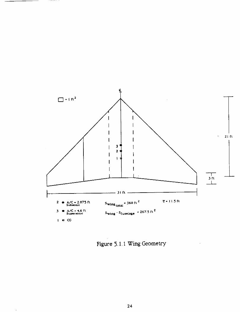
5.1 Wing Geometry
The design of the wing for the Gremlin is a 31 foot span with a lead-
ing edge angle of 50 degrees. The wing has a reference area of 360 square
feet. This was determined from wing loading requirements and compari-
sons with historical data. The root to tip ratio is 7 to I. The trailing edge
has an angle of 8.74 degrees (see Figure 5. I. I ).
To determine the mean aerodynamic chord, a method that involves
geometry was used. A line equal in length to the root was added to the tip
while a line equal in length to the tip was added to {he root thus creating
a box. From this, two lines were drawn connecting opposite corners of the
box. The point where the two lines intersected labeled the mean aerody-
namic chord. The chord length was determined to be 11.5 feet. At half of
the mean aerodynamic chord length, a line was drawn perpendicular
towards the center line. This point represents the c.g. location of the wing.
Another aspect of the wing determined was the location of the aero-
dynamic center for both subsonic and supersonic flight regimes. The sub-
sonic aerodynamic aerodynamic center was determined to be 25 percent
of the mean chord and the supersonic aerodynamic center is located at
40-percent of the mean chord.
23
[] - I ft 2
3
2
2 O A/C - 2.875 ft$ubsom.c
3 • A/C-4.6ftSul_rsoruc
I *U CG
31 ft
Swingtota I - 360 ft 2
Swing - Sfuselag e - 267.5 ft 2
_- I 1.5 f%
---7-3 ft
___L_
2 ft
Figure 5. I. I Wing Geometry
24
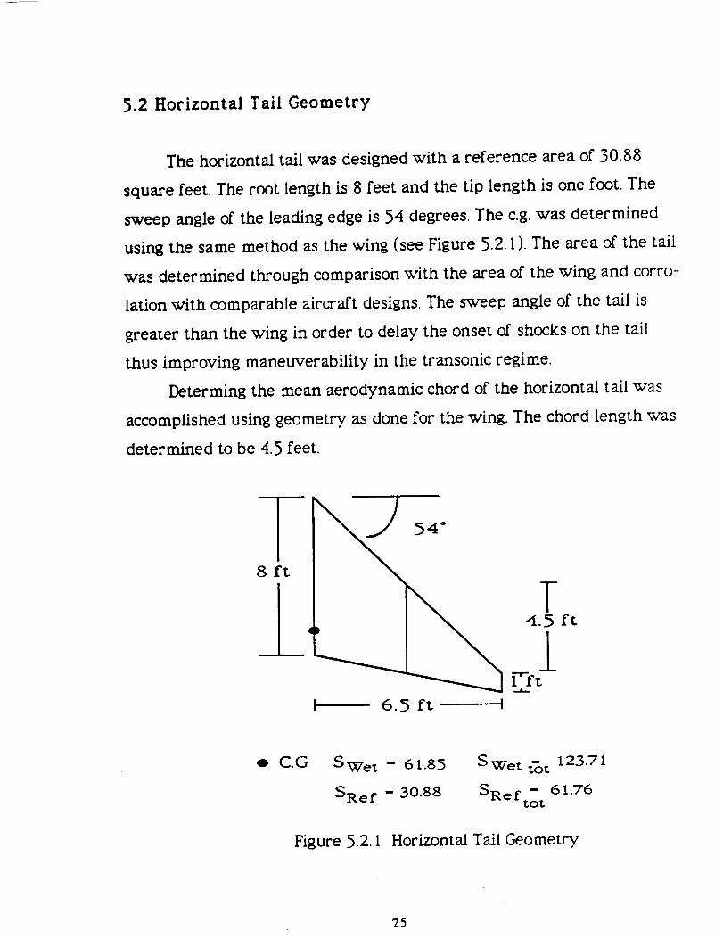
5.2 Horizontal Tail Geometry
The horizontal tail was designed with a reference area of 30.88
square feet. The root length is 8 feet and the tip length is one foot. The
sweep angle of the leading edge is 54 degrees. The c.g. was determined
using the same method as the wing (see Figure 5.2. I ). The area of the tail
was determined through comparison with the area of the wing and corro-
lation with comparable aircraft designs. The sweep angle of the tail is
greater than the wing in order to delay the onset of shocks on the tail
thus improving maneuverability in the transonic regime.
Determing the mean aerodynamic chord of the horizontal tail was
accomplished using geometry as done for the wing. The chord length was
determined to be 4.5 feet.
I 6.5 ft !
o C.G S Wet = 61.85 S Wet t_t 123.71
= 61.76SRe f - 30.88 SReftot
Figure 5.2. I Horizontal Tail Geometry
25

5.3 Vertical Tail Geometry
The vertical tail was designed with a height of 7.5 feet, a root length
of 9.25 feet and a tip length of 2.25 feet. The leading edge angle is 50
degrees. The vertical tall has a reference area of 40.36 square feet (see
Figure 5.3. I ).
2.2 5 ft
o
9.2 5 ft ]
Swe t = 80.85
SRef = 40.36
7.2 5 ft
Figure 5.3. l Vertical Tail Geometry
26

5.4 Control Surface Sizing
Control surfaces are very critical to an aircraft's performance. The
three primary control surfaces vital to an aircraft are the aileron to con-
trol roll, the elevator to control pitch, and the rudder to control yaw. The
final sizes depend on dynamic analysis for control effectiveness. But, for
initial sizing, historical data can be used. The ailerons typically extend
from about 50 to 90 percent of the wetted span of one wing. But, because
of the Gremlin's wing fold location, the ailerons had to be placed 62 to I00
percent of the wetted wing span of one wing (see Figure 5.4.1 ).
A major drawback to ailerons on high speed aircraft is the phe-
nomenon called "aileron reversal". This is when for.ces produced by the air
flow twists the wing. At a certain velocity, the wing could possibly twist
so much that a rolling moment that occurs from the twisted wing can be
much greater than the rolling moment that the aileron generates. This
tends to have an adverse effect on the aircraft, making it roll in the oppo-
site direction. To combat this effect, many aircraft use inboard ailerons.
But, due to the nature of vectored thrust, inboard aileron_ do not have to
be used.
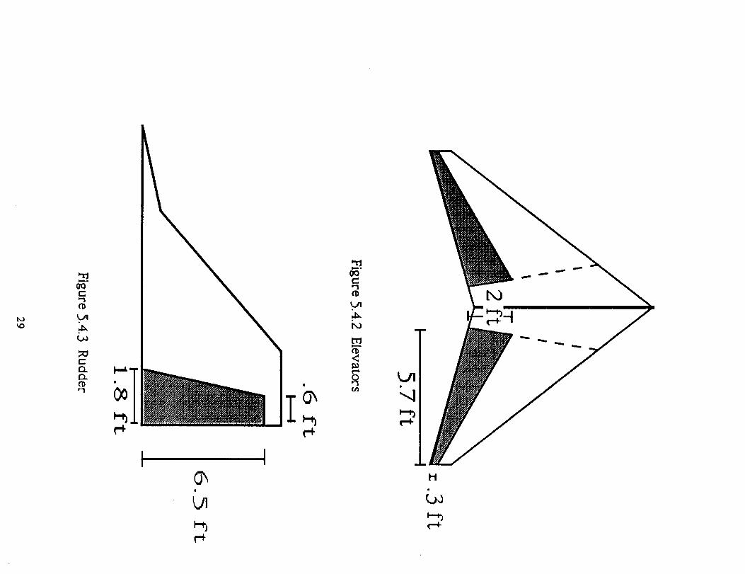
For most aircraft, the elevators and rudder start from the fuselage
to 90% of the span. This is the specification used in the Gremlin's control
surface sizing in the tail (see Figures 5.4.2 and 5.4.3).
27

2.1 ft
Figure 5.4. I Ailerons
28
IJ
im, o
t.P'I
ID.
G_ii
UI
Immo
t!
I'D
r-l-0
I-I
6. Rubber Engine
Due to a lack of information and data on production and future
engines, the Gremlin has been fitted with a rubber engine. Using experi-
mentally derived equations, an engine may be created to fit the needs of
a particular airplane. This is known as a rubber engine. The advanced,
supersonic Pegasus I 1-61 was the desired engine to power the Gremlin,
but very few actual parameters were available. Without these parame-
ters, the Gremlin could not have been designed. The Pegasus is classified
through the British government and Rolls Royce possesses proprietorship
of all Pegasus data. Neither the British government nor Roils Royce would
voluntarily release any specific information on the Pegasus. Also, two
engines were provided as part of the design contest options. Neither of
these engines met the needs of the Gremlin.
One of the engines provided was a Rolls Royce direct lift engine.
Since two engines are required when a direct lift engine is utilized, the
weight of the airplane is much greater than with only one engine. Also,
during horizontal flight, the direct lift engine is dead weight since it con-
tributes no thrust. The need to stock two engines and spare parts is an-
other drawback. Since the Gremlin will take advantage of vectoring thrust
during flight, the direct lift engine could not be used since it does not
possess this capability.
The other engine provided is a purely conceptual engine in terms of
today's technology and will not be in production for about two decades.
This engine does not fit the requirements of the Gremlin since it is a three
poster instead of four poster engine and did not produce enough thrust.
The number of posters of an engine refers to the number of nozzles pro-
viding thrust.
3O
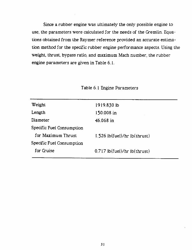
Since a rubber engine was ultimately the only possible engine to
use, the parameters were calculated for the needs of the Gremlin. Equa-
tions obtained from the Raymer reference provided an accurate estima-
tion method for the specific rubber engine performance aspects. Using the
weight, thrust, bypass ratio, and maximum Mach number, the rubber
engine parameters are given in Table 6. I.
Table 6. I Engine Parameters
Weight
Length
Diameter
Specific Fuel Consumption
for Maximum Thrust
Specific Fuel Cons u m ption
for Cruise
1919.830 Ib
150.008 in
46.068 in
1.526 Ib(fuel)/hr Ib(thrust)
0.717 Ib(fuel)/hr Ib(thrust)
3i
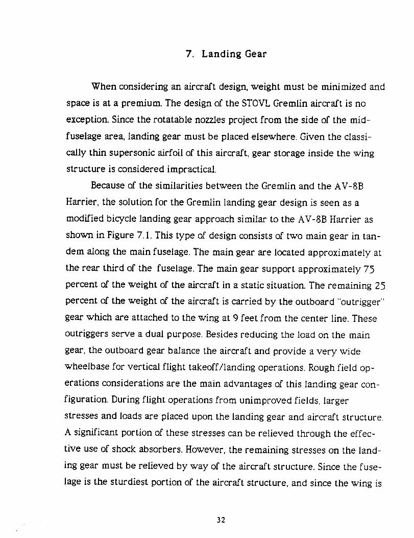
7. Landing Gear
When considering an aircraft design, weight must be minimized and
space is at a premium. The design of the STOVL Gremlin aircraft is no
exception. Since the rotatable nozzles project from the side of the mid-
fuselage area, landing gear must be placed elsewhere. Given the classi-
cally thin supersonic airfoil of this aircraft, gear storage inside the wing
structure is considered impractical.
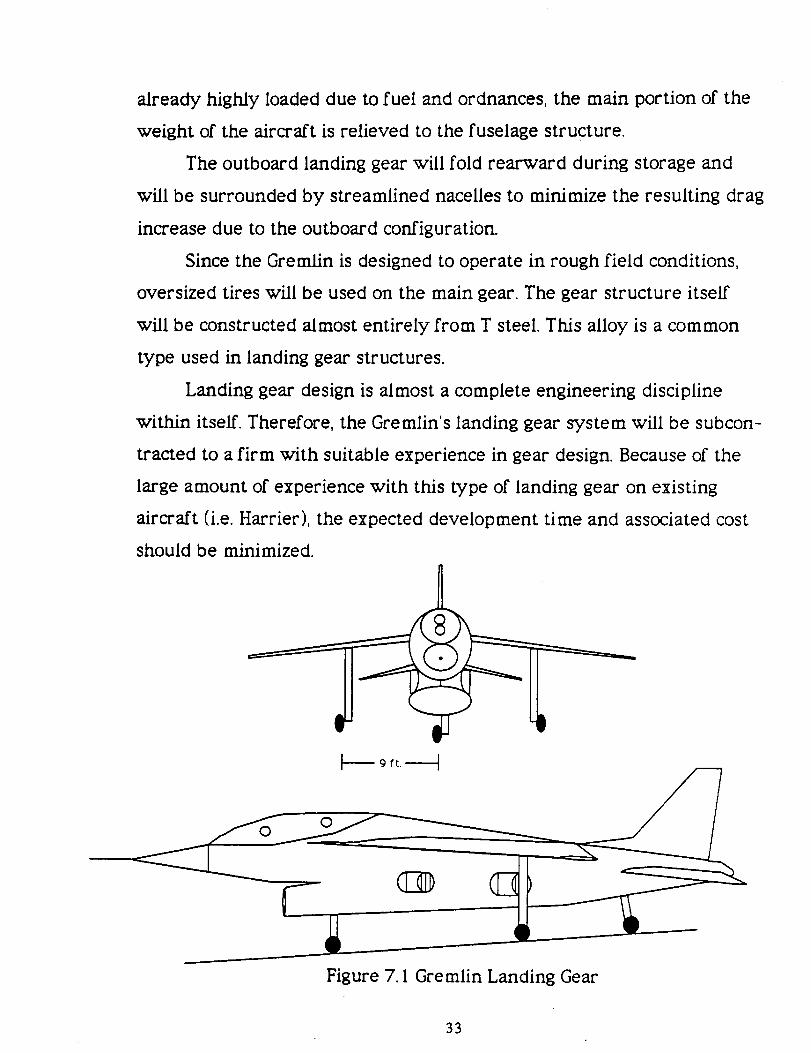
Because of the similarities between the Gremlin and the AV-8B
Harrier, the solution for the Gremlin landing gear design is seen as a
modified bicycle landing gear approach similar to the AV-8B Harrier as
shown in Figure 7. I. This type of design consists of two main gear in tan-
dem along the main fuselage. The main gear are located approximately at
the rear third of the fuselage. The main gear support approximately 75
percent of the weight of the aircraft in a static situation. The remaining 25
percent of the weight of the aircraft is carried by the outboard "outrigger"
gear which are attached to the wing at 9 feet from the center line. These
outriggers serve a dual purpose. Besides reducing the load on the main
gear, the outboard gear balance the aircraft and provide a very wide
wheelbase for vertical flight takeoff/landing operations. Rough field op-
erations considerations are the main advantages of this landing gear con-
figuration. During flight operations from unimproved fields, larger
stresses and loads are placed upon the landing gear and aircraft structure.
A significant portion of these stresses can be relieved through the effec-
tive use of shock absorbers. However, the remaining stresses on the land-
ing gear must be relieved by way of the aircraft structure. Since the fuse-
lage is the sturdiest portion of the aircraft structure, and since the wing is
32
already highly loaded due to fuel and ordnances, the main portion of the
weight of the aircraft is relieved to the fuselage structure.
The outboard landing gear will fold rearward during storage and
will be surrounded by streamlined nacelles to minimize the resulting drag
increase due to the outboard configuration.
Since the Gremlin is designed to operate in rough field conditions,
oversized tires will be used on the main gear. The gear structure itself
will be constructed almost entirely from T steel. This alloy is a common
type used in landing gear structures.
Landing gear design is almost a complete engineering discipline
within itself. Therefore, the Gremlin's landing gear system will be subcon-
tracted to a firm with suitable experience in gear design. Because of the
large amount of experience with this type of landing gear on existing
aircraft (i.e. Harrier), the expected development time and associated cost
should be minimized.
Figure 7. I Gremlin Landing Gear
33

8. Weapons System
The gun has been the main weapon of fighter engagements since the
dawn of air combat during WWI. Even though the use of air-to-air mis-
siles have limited the use of the gun, it is still an invaluable weapon sys-
tem.
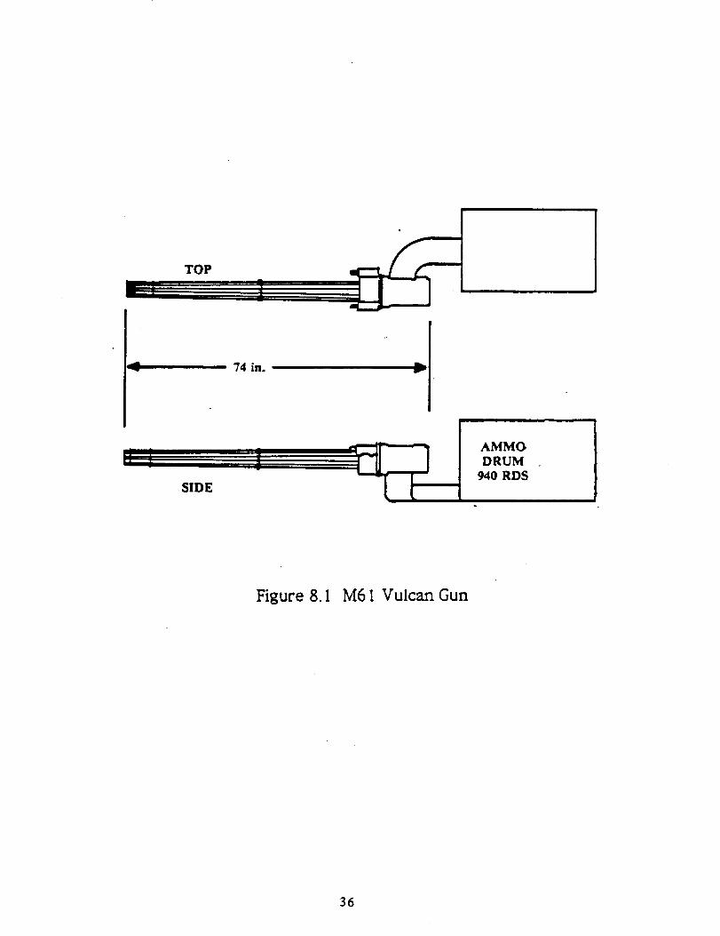
The standard U.S. gun installed in all fighters is the M61A I "Vulcan"
six-barrel Gatling gun (Figure 8. I ). In order to maintain compatibility
with U.S. forces, this is the choice for the Gremlin aircraft.
An ammunition container is attached to the gun for easy reloading
and ammunition handling. The Vulcan can produce up to two tons of re-
coil force, therefore, it is prudent to place the gun near the center line of
the aircraft to prevent a sudden yawing moment.
When fired, the Vulcan produces a bright Hash and a cloud of
smoke. The gun muzzle was positioned where the muzzle flash is not
harmful to the pilot's vision. The gun was also placed where gases from
the smoke cannot cause a jet engine to stall if it is ingested into the inlet.
The purpose of most military aircraft is to act as a platform to
transport weapons to destroy targets. Weapons can consist of missiles,
bombs, and guns.
Missiles can be launched from aircraft by two methods. The AIM-9
Sidewinder that the Gremlin is designed to carry is rail launched. A rail-
launcher is attached to either the wing-tips or underwing pylons. The
missile has several mounting lugs, which slide onto the launcher. When
launched, the propulsive force from the missile moves it along the rail
and slides free of the aircraft. The Gremlin will employ wing tip mounted
launchers as well as pylon launchers for sidewinders.
34
Ejection-launch is mainly used for large missiles. The missile is
attached to the aircraft by hooks powered by explosive charges which can
release very quickly. The explosive also powers two pistons, which push
the missile away from the body of the aircraft. Bombs can also be re-
leased in this manner or they can be released in free fall. This method is
considered undesirable for the Gremlin.
Because of the size limitations inherent to all fighter aircraft, the
capability to have the weapons stored inside a weapons bay is not pos-
sible. The only option left for the Gremlin is the placement of weapons
externally. This type of carriage calls for hardpoints under the wing and
fuselage to which weapon pylons are attached. These pylons are dropable
for maximum dog fighting capability. The Gremlin can also carry external
fuel tanks on the pylons. These fuel tanks are jettisoned during air-to-air
combat.
A major drawback to externally carried weapons is the extremely
high drag that the weapons produce. When an aircraft approaches Mach
one with an external load of weapons, the weapons can produce more
drag than the aircraft generates.
The location of missiles and bombs relative to other aircraft compo-
nents and the ground was considered. A minimum clearance of three
inches above the ground was required when designing the Gremlin. This
requirement is for the scenario that one tire and shock strut goes flat and
the aircraft has a five degree roll. When weapons are placed near each
other there is a minimum of three inches clearance between them.
3S
TOP
74 in.
SIDE
AMMODRUM
940 RDS
Figure 8. I M61 Vulcan Gun
36

9. I Hydraulics
9. Special Considerations
The hydraulic system in an aircraft pressurizes hydraulic fluid by a
pump and stores it in an accumulator. When a valve is opened by a con-
trol stick, the pressurized hydraulic fluid flows to an actuator to move a
piston that moves the control surfaces. The hydraulic fluid is then re-
turned to the pump by a return line. In more recent aircraft designs, a
fly-by-wire approach is used instead of the hydraulic system. A fly-by-
wire system transforms the pilot's inputs into electrical impulses and
sends them as values to the actuator.
CONTROL STICK
ACCUMULATOR
_m
PUMPRETURN LINE
CONTROL CONTROLCABLES SURFACE
VAI.VE
ACTUATOR
Figure 9. I. I Simplified Hydraulic System
37
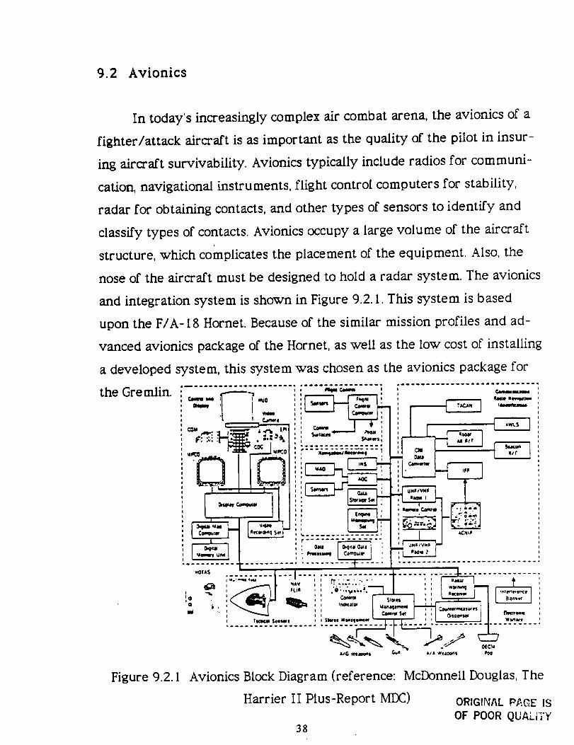
9.2 Avionics
In today's increasingly complex air combat arena, the avionics of a
fighter/attack aircraft is as important as the quality of the pilot in insur-
ing aircraft survivability. Avionics typically include radios for communi-
cation, navigational instruments, flight control computers for stability,
radar for obtaining contacts, and other types of sensors to identify and
classify types of contacts. Avionics occupy a large volume of the aircraft
structure, which complicates the placement of the equipment. Also, the
nose of the aircraft must be designed to hold a radar system. The avionics
and integration system is shown in Figure 9.2. I. This system is based
upon the F/A-18 Hornet. Because of the similar mission profiles and ad-
vanced avionics package of the Hornet, as well as the low cost of installing
a developed system, this system was chosen as the avionics package for
the Gremlin. _"i,_=- _ _., ,,,,_ ,,li'_'"'i I.... _;_' ..... ! i ......... _'"_""
............ ] L.'_'.."7.._.. : ................. ]
I q&V ) I • • • o4_ . o. . I I
o i I _@,C_W
.....,..-..,:.-.,....:&,_G W_lCm_$ _ A,' A we4OGn's P_I
Figure 9.2. I Avionics Block Diagram (reference: McDonnell Douglas, The
Harrier If Plus-Report MDC) ORIGINAL P_.C,E )S
Of POOR QUALITY38

9.3 Crew Station
The crew station of an aircraft must be designed primarily for the
pilot to have unobstructed outside visibility and efficient access to all
instruments. Generally, crew stations are designed to accomodate the
average pilot size in which 95 % of all pilots fall.
The crew station has two main reference points that determine its
dimensions. The point on the seat where the pilot's back meets the bench
is the point of reference for the floor height and the leg room. The point
where the pilot's eyes are located is the second reference point. This ref-
erence point is the base where the overnose angle, transparency grazing
angle, and pilot's head clearance are found (Figure 9.3. I ).
The Gremlin's crew station layout uses a 17 degree seat tilt-back
angle. This reduces the visibility somewhat from the standard 13 degrees,
but it enhances the pilot's ability to withstand high-g turns and can also
lead to reduced drag because the canopy can be made smaller.
Overnose vision is very important, especially in the landing stage
and in air-to-air combat. Military specifications require an I I- 15 degree
overnose angle for fighter and attack aircraft. The Gremlin achieves an
I 1.5 degree angle as seen in Figure 9.3. I.
Typically, fighters and attack aircraft have a 40 degree over-the-
side angle. The Gremlin achieves a 43 degree over-the-side angle.
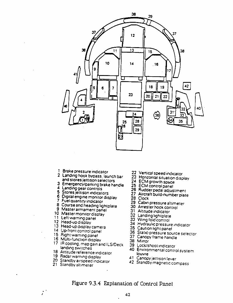
The pilot control panel integrates the F/A-18 Hornet's and AV-8B
Harriet's systems. From Figures 9.3.3 and 9.3.4, the displays and controls
can be seen. These systems are taken mostly from the Hornet. Using the
Hornet's displays and controls allows the manufacturer to keep costs
down by using already existing systems. A major modification to the
39

aircraft's design is that the throttle is removed and a Harrier throttle and
nozzle control are installed. This allows for the vectoring of the nozzles as
well as thrust control (Figure 9.3.5).
PILOT'S EYI
I
!17 DEe I
IIi
SEAT REFERENCE POINT
Figure 9.3. I
50 IN
Crew Station Geometry
CROSS SECTION
*_ HEAD
/-_ IN
43 o_e ----(_J_" ;7-- _,-,,.-I
.- //
CLEARANCE
Figure 9.3.2 Pilot Visibility
40

/PF,
/
\
Figure 9.3.3 Pilot's View of Control Panel
41
3839
10
23 l®
37
38
1 Brake pressure indicator2 Landing hook bypass, launch bar
and stores jettison selectors3 EmergencWparking brake handle4 Landinc::jgear controls5 Stores jettison indicators
6 Digital engine monitor display7 Fuetquant=ty indicator8 Course and heading lightplate9 Master armament panel
10 Master monitor display11 Left warning panel12 Head-updisplay13 Head-up display camera14 Up-front control panel15 Right warmng panel16 Multi-functfon dislolay17 IR cooling, map gain and ILS/C)eck
landing switches18 Attitude reference indicator19 Radarwarn,ngd=splay20 Standby airspeed indicator21 Standby altimeter
22 Vertical speed indicator23 Horizontal s_tuatJon d_splay24 ECM growth space25 ECM controlpanel26 Rudder pedal adjustment27 Aircraft build-number plate:28 Clock29 Cabin pressure altimeter30 Arrester hook control31 Altitude indicator32 Landing lightplate33 Wing fold control34 Hydraulic pressure _ndicator35 Caution light panel36 Static-pressure source selector37 Canopy frame handle38 Mirror39 Lock/shoot indicator40 Environmental control system
louvre41 Canopyjettfson fever42 Standbymagnet)c compass
#
Figure 9.3.4 Explanation of Control Panel
42
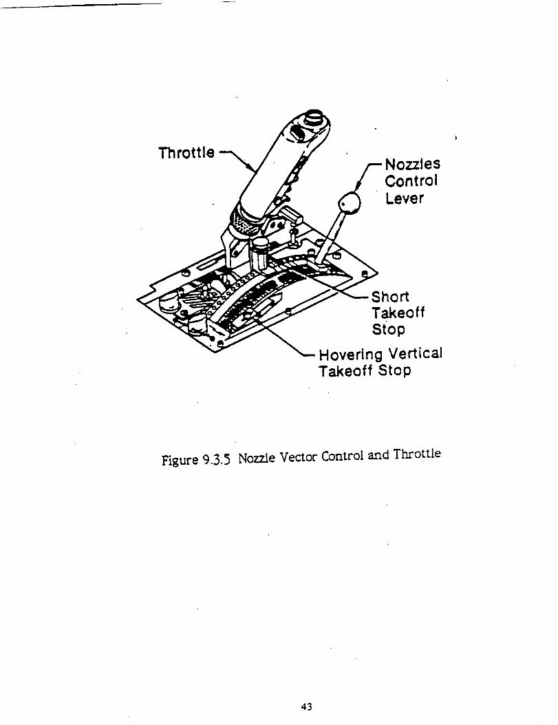
ThrottleNozzlesControlLever
ShortTakeoffStOp
Hovering VerticalTakeoff Stop
Figure 9.3.5 Nozzle Vector Control and Throttle
43
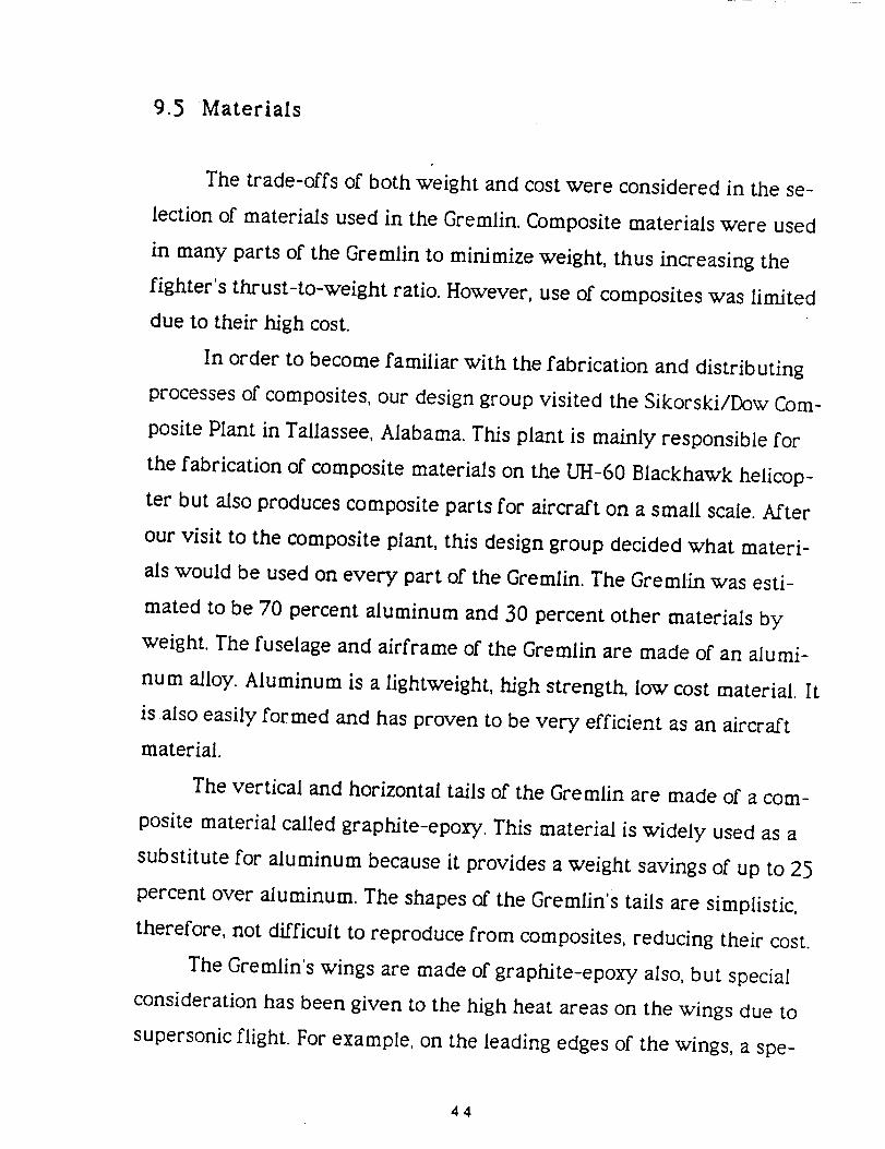
9.5 Materials
The trade-offs of both weight and cost were considered in the se-
lection of materials used in the Gremlin. Composite materials were used
in many parts of the Gremlin to minimize weight, thus increasing the
fighter's thrust-to-weight ratio. However, use of composites was limited
due to their high cost.
In order to become familiar with the fabrication and distributing
processes of composites, our design group visited the Sikorski/Dow Com-
posite Plant in Tallassee, Alabama. This plant is mainly responsible for
the fabrication of composite materials on the UH-60 Blackhawk helicop-
ter but also produces composite parts for aircraft on a small scale. After
our visit to the composite plant, this design group decided what materi-
als would be used on every part of the Gremlin. The Gremlin was esti-
mated to be 70 percent aluminum and 30 percent other materials by
weight. The fuselage and airframe of the Gremlin are made of an alumi-
num alloy. Aluminum is a lightweight, high strength, low cost material. It
is also easily formed and has proven to be very efficient as an aircraft
material.
The vertical and horizontal tails of the Gremlin are made of a com-
posite material called graphite-epoxy. This material is widely used as a
substitute for aluminum because it provides a weight savings of up to 25
percent over aluminum. The shapes of the Gremlin's tails are simplistic,
therefore, not difficult to reproduce from composites, reducing their cost.
The Gremlin's wings are made of graphite-epoxy also, but special
consideration has been given to the high heat areas on the wings due to
supersonic flight. For example, on the leading edges of the wings, a spe-
44

cial composite strip of polymide is placed to withstand the intense heat.
Polymide is a composite which will withstand temperatures up to 600
degrees Fahrenheit, but is difficult to process, thus is very expensive to
use in large quantities.
The radome of the fighter is made of a composite called airamid.
This material provides easy visibility for the radar. The fighter's canopy
is made of a single piece of stretched acrylic. This material has high
strength as well as provides good pilot visibility.
The engine nozzles and landing gear are made of a steel alloy
(4130). This material is a steel alloy of chromium and molybendum com-
position and is notable for its high strength as well as good fatigue resis-
tance. Steel is relatively easy to fabricate and is relatively inexpensive.
The "hot spots" around the engine are made of titanium. Titanium
has a better strength-to-weight ratio than aluminum and is capable of
withstanding extremely high temperatures. However, titanium is ex-
tremely expensive so it was not used extensively in the Gremlin. The
engine inlet is made of a composite capable of withstanding high tem-
peratures.
45
9.5 On Board Oxygen Generating System (OBOGS)
At high altitudes, the pilot of a fighter needs an oxygen supply be-
cause of the low air density associated with higher altitudes. There are
basically two ways to provide this oxygen supply. One option is the outfit-
ting of aircraft with liquids or compressed oxygen. This method was used
in almost all fighters, but proved quite dangerous in case the liquid or
compressed oxygen cannisters were to rupture.
OBOGS provides oxygen to the pilot from air bleed off from the en-
gine compressor that is run through a processing unit. The OBOGS method
was determined to be the most suitable option of providing oxygen to the
pilot in a forward based area where oxygen cannisters may not be readily
handy. This system is currently in operation in fighters like the General
Dynamics F- 16C.
46
I 0. Survivability/Vulnerability
In order for an aircraft to survive air combat, it must have several
features. Among the most important are speed, maneuverability, and still
the most important of all, a competent pilot.
The most useful method to reduce air combat vulnerability is the
use of redundant systems. By duplicating the major systems of an aircraft,
survivability is enhanced considerably. The main redundant systems on
an aircraft include redundant fuel lines, hydraulic lines and electrical
cables.
Although most combat aircraft designs incorporate redundant sys-
tems to reduce vulnerability, oftentimes these systems are not positioned
effectively. The dual lines are sometimes designed to be run parallel to
each other with very little space between them. In tl_s case, a single
projectile could disable both the primary and secondary systems thus
completely disabling the aircraft. This may seem fairly obvious as a de-
sign consideration but two notable aircraft, the F-105 and F-11 I, did not
take this aspect of vulnerability into account and had many combat losses
due to this oversight. (reference: Richardson, Steve)
Redundant systems are not always a sign of increased survivability.
A notable example of this case is multi-engine aircraft. A multi-engine
aircraft would seem to be less vulnerable than a single engine aircraft
because of the redundant engine(s). However, this is not always the case.
If an aircraft has multi-engines, this means its weight and performance
was designed around this factor. If one of these engines fails, steady flight
is not insured. Usually the increased yaw and reduced handling due to the
lost engine dictates a very quick landing. This landing is not always a safe
one. There is a statistic which best illustrates the misconception that two
47

engines equals survivability. During the Vietman War two engine fighters
had a significantly higher rate of combat losses than single engine fight-
ers. (reference: Richardson, Steve)
Fire onboard an aircraft is the worst fear of a pilot. This almost
certainly spells disaster. In order to reduce the chance of ignition as well
as propagation of flame onboard an aircraft, several options can be incor-
porated into a design. Most important is the use of firewalls to prevent
the spread of fire from one compartment to another.
Conventional wisdom dictates that in order to minimize the possibil-
ity of fire onboard an aircraft, it is necessary to keep the fuel as far away
from the engine as possible. This is suggested in order to keep fuel from
coming in contact with the hot engine. However, in the Gremlin STOVL
configuration the fuel and engine must be placed together. This is neces-
sary for two reasons. In order to have vertical flight the vectored thrust
must be balanced around the center of gravity (c.g.). Therefore, the engine
must be placed at the aircraft's c.g. Also, in order to minimize c.g. shift
during a long flight, the main fuel tanks must be placed about the c.g.
A way to prevent fires from starting in a fuel cavity is by filling all
empty spaces with an inert gas such as nitrogen. The Gremlin's onboard
oxygen system (OBOGS) separates the oxygen and nitrogen from the air.
The oxygen is obviously used for the crew. However, the inert nitrogen
could be pumped into the voids of fuel tanks and other areas where spark
propagation and static charges as well as combat danger could cause a fire
or explosion. The inert gas, in conjunction with self sealing fuel tanks, is a
design safety measure which cannot be ignored.
Visual detectability is also a consideration for combat survivability.
In modern air combat, with long range radar and night vision sensors, it
48

seems archaic to be concerned with camouflage. However, visual sighting
is the most important factor in a close dog fight situation. By painting an
aircraft a color of grey which blends in with both sea and sky, a few vital
seconds may be gained before an opponent has a chance to react. Since
most air combat kills occur on the first surprise pass, visual indetectabil-
ity is a cheap method of helping to insure the success of an aircraft in
combat.
In a worst case scenario, an aircraft is damaged to the point where
it is uncontrollable. In this case, a pilot must eject from the aircraft. Since
the pilot is the most important system in an aircraft, it is extremely im-
portant to insure his survival.
Many modern ejection seats use the term "zero-zero" to describe
their performance. A "zero-zero" ejection seat is expected to eject a pilot
safely and have the parachute fully deploy before reaching the ground in
a situation where the aircraft is at zero altitude and zero airspeed. Ad-
vanced ejection seats are being developed which should be able to safely
eject a pilot from a inverted flight condition. The aircraft also experiences
some significant sink rate. While this development will be a welcome
advance for pilots, it awaits experimental validation before installation in
production aircraft.
Because of the importance of having the most advanced escape
system available, a "zero-zero" ejection seat system designed and con-
structed by the Martin-Baker Company was selected for installation in the
Gremlin aircraft. In the reasonable event that a more advanced ejection
system becomes available before production of this aircraft occurs, the
new seat could be installed with only a small amount of engineering work
necessary.
49

In conventional vertical flight aircraft, a cockpit canopy is designed
to open from the front. This feature is designed to take advantage of the
force of the wind during ejection from an aircraft. When a canopy of this
type is opened only a small amount during forward motion, the wind
blast rips the canopy away from the aircraft almost immediately. This
situation frees the only major obstruction from the path of an ejecting
pilot.
However, in a STOVL aircraft such as the Gremlin, a crucial portion
of a flight occurs in vertical flight operations when there is an insignifi-
cant airflow across the canopy. To prevent significant injury to the pilot/
copilot, the canopy shell will be removed by the use of explosive cord
embedded in the acrylic shell of the canopy. This is common practice and
can be seen in several production aircraft such as the AV-8B and T-45.
50
1 I. Performance
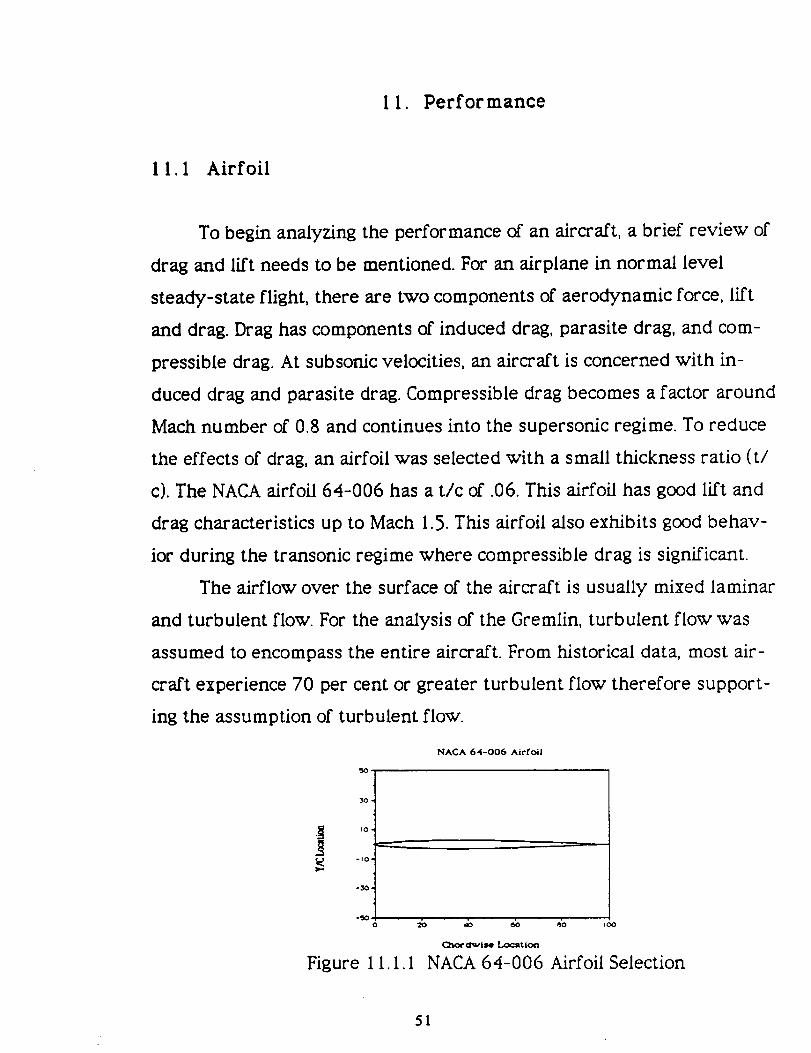
1 I.I Airfoil
To begin analyzing the performance of an aircraft, a brief review of
drag and lift needs to be mentioned. For an airplane in normal level
steady-state flight, there are two components of aerodynamic force, lift
and drag. Drag has components of induced drag, parasite drag, and com-
pressible drag. At subsonic velocities, an aircraft is concerned with in-
duced drag and parasite drag. Compressible drag becomes a factor around
Mach number of 0.8 and continues into the supersonic regime. To reduce
the effects of drag, an airfoil was selected with a small thickness ratio (t/
c). The NACA airfoil 64-006 has a t/c of .06. This airfoil has good lift and
drag characteristics up to Mach 1.5. This airfoil also exhibits good behav-
ior during the transonic regime where compressible drag is significant.
The airflow over the surface of the aircraft is usually mixed laminar
and turb ulent flow. For the analysis of the Gremlin, turbulent flow was
assumed to encompass the entire aircraft. From historical data, most air-
craft experience 70 per cent or greater turbulent flow therefore support-
ing the assumption of turbulent flow.
NACA 64-006 Airfoil
30,
J io.
_ -I0"
Figure I I. I. I
=b _b _b _o ,oo
C)'K_ Ulwlso Loc_tlon
NACA 64-006 Airfoil Selection
51
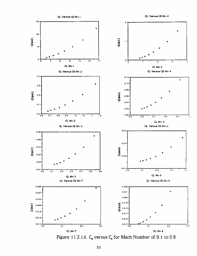
I 1.2 Drag Polar
The first step in analyzing the Gremlin was to create a CD versus CL
plot, Figurel 1.2. I. These plots were created from M=. i to M=I.5 with each
plot containing data from sea level to 35000 feet. Plots were generated
for mission configuration containing missiles and subsonic configurations
with Mk-82s. From the drag polars, we are able to create plots of Drag
versus Mach number and CD versus Mach number. From these plots it will
be necessary to reuse data from the drag polars. The following sections
will provide more detail on the analysis.
52
CL Versus C]:) M-. I CL Versus CD M-.2
_E
8
_E
0
_E
E_
_E
8
30
20'
I0 ¸
0
2
0,1-
03-
02-
Ol
O0
02
0 0_-
00=3 •
0 0-1,
0.03 •
002"
O0!
0.0
0 02G •
002-1 -
0022 -
0020 -
0Or8
0016
001,1
O0
m
o'._
m
C3.. M°. !
CL Versus CD M-.3
,'2
CL M-3
CL Versus CO M-.5
Oi 2 O' 3 O' -1
CL M-.5
CL Versus CI) M-.7
o'_
O' I O' 2
M-.7
Figure 11.2.1A
1-1
0
0
OO
012,
OlO-
0 08 "
006.
0 0-1.
002-
000
O0
0 0-1
ii
CL M-2
(1 Versus CD M-4
m
am •
O' 2 O' .I 0' _,
CLM=4
CL Versus CZ) M- &
o'_
o6
0 03
00:
OOtO0 0'1 0"2
C"r M-.6
o"_
CL Versus CD M-8
mE
0
m m
0 022
0021
o 020
OOl_=
001_
0017-
00t6-
001".'3
O0
i
i
O' I0 3 0'2
CLM-8
CDversus CLfor Mach Number of 0. I to 0.8
53

O.O'-_';
X
O
OUIU
O,01b0.0
U.(_',_'_
:2
8
i=E
8
¢) U'_ '
0 U"_'I u
:E
CL Versus CO M-.9
ee
m
mill •
o',
CL M=.9
C_ Versus CO M= t,2
0.2
(_.. M-I.!
CL Versus CO M= t.3
olo
iiii •
CL M-I.3
CL Versus CO M-1.5
uL_
0
o o'_',4
(J 0"_¢) •
o Ul_,
o ol_
o U'db
x
0o o2,s,
002
O O_JO °
=E
U 0_ _
001
o_..,
C_ Versus CO M- [.0
(EL M-[.O
(1 Versus CO M-I.2
i
CL M-I.2
CL Versus CO M- 1.4
i
, , )
CL M-|.4
-" O U2
m
ii
C_ M-[.5
Figure 11.2. IB Co versus CL for Mach Numbers 0.9 to 1.5
54

I 1.3 Drag versus Mach Number
Converting the CD coefficient to Drag was done for M=. I to M= 1.5 at
all altitudes. Figure l 1.3. I shows the results obtained from graphing Drag
versus Mach number. From this graph, the drag generated at all altitudes
and velocities can be determined. For example, at 35000 feet there is
approximately 5500 pounds of drag generated, which is less than the
thrust generated proving that M= 1.5 at 35000 feet is possible. Also from
the graph, at sea level, M=I.5 there is 27000 pounds of drag. This is 1.2
times the amount of thrust capable of being generated. Therefore M= 1.5
at sea level conditions cannot be accomplished.
Drag Versus Mach Number
30000 1
2o0oo1
1000001
0.4 0.6 0.8 1.0 1.2 I 4 5
------I-----
sealevel
5000
10O0O150OO20000
25000
30000
35000
Mach Number
Figure 11.3. I Drag Versus Mach Number
55

11,4 CD versus Mach Number
In order to determine the best cruise Mach number and altitude, it
is necessary to generate a CD versus Mach number graph, Figure 1 1.4. I.
From the graph, the best cruise Mach number was determined to be
M,-.89. After determining this value, a line was drawn tangent from the
origin to the CL versus CD plot for the drag polar graph at M=.9. An itera-
tion revealed the best cruise altitude to be at 30000 feet.
0.04
Determination of Best Cruise Mach Number
0.03
0.02
Best Cruise Mach Number
-=-=m--= Sea Level
' 5000: 10000E
15000E: 20000E
---m--- 25000E30000_35000_
0.010.4 0.6 O.8 1,0
Mach Number
12
Figure 1 1.4.1 Determination of Best Cruise Mach Number
56

July 24, 1990:
Pages 57, 58, and 59 removed because of
funding information.
k__ PHI,L/IP N. FRENCH
Document Evaluator

13. Discussion
When designing an aircraft there are many design options that an
engineering team explores. In many ways, an aircraft that has a defined
mission profile can design itself. However, many times there are conflict-
ing expectations outlined in requests for proposals (RFP) which can com-
plicate design efforts. The AIAA RFP outlines the mission requirements
for the STOVL aircraft design. In this RFP, the (expensive) supersonic dual
role (fighter/attack) nature of the aircraft is discussed. The expected use
of (expensive) advanced materials and avionics is outlined in relative
detail. However, the RFP also expects this aircraft to be "low cost" as to be
suitable for export. This conflict was intentionally produced in order to
challenge this design team to conceive unique solutions to the never end-
ing challenge to restrict the cost of an aircraft program.
Aircraft design is a science. However, it is far from being an exact
science. A preliminary design is based on both mission requirements and
experience of the group designing the aircraft. The aerodynamic configu-
ration of an aircraft is determined through numerical aerodynamic analy-
sis as well as through observation of historical trends concerning similarly
performing aircraft. However, because of the complex aerodynamic nature
of today's aircraft, much predicted aerodynamic performance is inaccu-
rate and can only be verified through wind tunnel testing or perhaps
advanced CFD techniques. These aspects of aircraft aerodynamic perform-
ance analysis are outside the scope of this paper.
Aircraft design is also an iterative process. Many tradeoffs had to be
made in order to reduce aircraft cost with only a minimal reduction in
performance. Since development costs are a major percentage of an air-
60 PRECEDING PAGE BLANK NOT FILMED

craft program's total cost the reliance on developed systems is a valuable
tool to minimize cost. However, since this aircraft is not expected to fly
before the year 2005, several of the developed systems used in the Grem-
lin may then be obsolete.
A major example of this expected obsolescence is the Gremlin's
avionics package. Aircraft avionics is very fast paced. Although there are
several trends in avionics development, it would be foolish to try and
predict the cost, capability, and types of avionics available 15 years into
the future.
There have been announcements of programs to develop helmet
mounted heads up displays (HUD's) giving a pilot a "good eye view" of the
air combat area as well as "look and shoot" capability. Voice responsive
avionics have also been discussed for development. However, unknown
performance, weight, as well as acquisition and maintenance costs pre-
clude this proposal from considering such conceptual systems for its de-
sign.
Low observable (LO) technology was also suggested as a design
option in the RFP. Low observable technology includes both reducing the
effective radar cross section of an aircraft as well as reducing infrared
(IR) emissions. This is an extreme advantage in air combat as the two
main detection and targeting techniques use microwave and IR radiation
receivers in both an active and passive mode.
The only two known production aircraft to make full use of LO tech-
nology are the B-2 and F-117A. Since the technology and research used to
produce these aircraft is extremely sensitive (and therefore classified),
very little data is available to evaluate LO technology for use in this proj-
ect. However, the cost of these aircraft have been published and it seems
61

evident that LO technology is inherently expensive to develop and pro-
duce. Because of the cost considerations, LO technology was considered
incompatible with the "low cost" aspect of this aircraft's RFP guidelines.
Another challenge to this design group is the large amount of re-
search and data which is unavailable. The Gremlin aircraft is in no way a
duplication of the VTOL Harrier aircraft. However, since the Harrier is the
only operation VTOL aircraft in the western military inventory at this
time, much could be learned from the development efforts of McDonnell
Douglas and British Aerospace. Because of national security and proprie-
torship concerns in both the United States and Great Britain, much of the
STOVL Research and experimental data generated from the AV-8B Har-
rier development is unaccessible.
This is not to say that there is an absence of information available
about STOVL aircraft design and development. The detail and quality of
the published reports that are available is occasionally disheartening.
A solution to the problem of research was to visit and consult with
the engineers responsible for the development of the Harrier II at McDon-
nell Douglas in St. Louis, Missouri. The experiences of this design group at
McDonnell Douglas added immeasurably to the quality and scope of this
project. By consulting with the Harrier design engineers, there is a much
clearer understanding of how engineering decisions are formulated. Not
only did the McDonnell Douglas engineers respect the questions of this
group, but they also added their own professional input and voiced their
own problems concerning development of a supersonic STOVL aircraft.
62

14. Conclusions
The main objective of this design group was to design a fighter that
was mathematically feasible as well as capable of meeting its mission
requirements. This group accomplished both objectives. All performance
calculations done by this design group on the Gremlin either meet or
exceeded the AIAA's set requirements for a STOVL aircraft design. The
Gremlin is a supersonic STOVL aircraft that can sustain a 6.5g turn during
a flight speed of Mach .8 flight. The fighter can also meet the range and
payload requirements.
The mathematical feasibility of our aircraft design was proven by
various plots done on Excel. After creating plots of the drag polar, it could
be observed that for every altitude that the drag polar was calculated, all
curves approximated a textbook drag polar with a slight error due to
assumptions of data in the transonic regime. A graph of CD versus Mach
number for various altitudes matched expected curves and clearly
showed a distinction between different drag components during the flight
regime.
The final plot of drag versus Mach number at different altitudes
gave the expected trends of change in drag due to a change in Mach nu m-
bet. Also, unfeasible Mach numbers at certain altitudes could clearly be
seen from this graph.
This project and the design work involved has greatly enhanced our
overall understanding of various aeronautical engineering topics and their
interrelationships.
63

Bibliography
Beaver, Paul, The Encyclopedia of Aviation. London: Octopus Books Lim-ited, 1989.
Bhalla, Raj, Dow/United Technologies Company, Personal Conversationswith on January 16,1990.
Brasse¥'s DefensePublishers, Jump Jet the Revolutionary V/STOL Fighter2nd ed. USA, 1986.
Campbell Clinton, McDonnell Douglas, Personal conversations with onFeb I, 1990.
The Consumer Price Index: 1990 Revision Washington D.C.: U.S. Depart-ment of Labor, Bureau of Labor Statistics, 1990.
Etkin, Bernard, Dynamics of Flight 2nd ed. New York: John Wiley & Sons,1982.
Fluk, Hal, Advanced Short Takeoff and Vertical Landing (ASTOVL)/AIAAAirplane Study. Pratt and Whitney. August, 1989.
Gree.ly, Brendan M. Jr., Improved VTOL performance of TAV-8B addsrealism to attack force training. Aviation Week & Space Technology. Au-gust 3, 68-76, 1987.
Gunston, Bill, The Encyclopedia of Wold Air Power. Aerospace PublishingLimited, 1980.
Gunston, Bill and Mike Spick, Modern Air Combat I st ed. New York: CrownPublishers, Inc, 1983.
Higbee, Vincent, McDonnell Douglas, Personal conversations with on nu-merous occasions between Oct I0 and Mar 8, 1989.
Hill, Philip and Carl Peterson, Mechanics and Thermodynanmics of Propul-siorL Phihppines: Addison-Wesley Publishing Company, Inc., 1970.
Kandebo, Stanley W., Governments, industry pool supersonic STOVL ef-forts. Aviation Week & Space Technology, April I I, 34-36, 1988.
La_yton, Donald, Aircraft Performance. Chesterland, OH: Matrix Publishers,1988.
McClean, Dennis, McDonnell Douglas, Personal conversations with on Feb I,1990.
McDonnel Douglas, The Harrier II Plus-Report MDC/BAe-88001 McDonnellDouglas/British Aerospace November, 1988.
Marshall, Chris, The World's Great Interceptor Aircraft. New York: GalleryBooks, 1989.
64

Monk, Derek, McDonnell Douglas, Personal conversations with on Feb l1990.
Polasek, Brian, McDonnell Douglas, Personal conversations with on Feb I1990.
Raymer, Daniel P., Aircraft Design: A Conceptual Approach. Washington,D.C."American Institute of Aeronautics andAstronautics, 1989.
iRichardson, Steve, McDonnell Douglas, Personal conversations with on Feb, 990.
Richardson, Doug, Modern Warplanes. Salamander Books Limited, 1982.
Shevell, Richard, Fundamentals of Flight 2nd ed. Englewood Cliffs: PrenticeHall, 1989.
Taylor, J. H., Janes En_cyclopedia of Aviation Volume 2. London: Best-SellerPublications, I 14- I 15, 1989.
Van Der Veer, Mike, McDonnell Douglas, Personal conversations with onFeb I, 1990.
Vinson, john, Dox/United Technologies Company, Personal conversationswith on January 16, 1990.
Ward, Benjamin, ASTOVL Direct Lift Engine for AIAA Student ProjectPerformance and Installation Brochure. Roils Royce Inc. July, 1989.
Zakrzewski, Bob, McDonnell Douglas, Personal conversations with on Feb i990.
65
c_
,-f_SImDJ
O
(I)
t-'0
J.lb.
(IJ
CD
Trip to St. Louis
The first quarter of AE447 required a significant amount of research
in order for the design team to become familiar with the many aspects of
their design project. It was assumed at the outset that there would be
little problem finding the quality sources needed to gain a working
knowledge of STOVL aircraft performance and design. However, aside
from a few trade journals, such as Aviation Week, there were few cred-
ible or technical sources available. Since STOVL aircraft design is a rela-
tively unique area in aircraft engineering, traditional methods of analysis
did not always apply.
A solution to this problem was to communicate personally with
engineers at McDonnell Douglas responsible for development of the AV-
8B Harrier If. The AV-8B is the only STC)VL aircraft in western military
inventories at this time. Therefore, it would be a windfall for this project
if a professional relationship could be cultivated between McDonnell
Douglas engineers and the Auburn University STOVL project design team.
Through phone conversations and correspondence, the Auburn
STOVL team discussed aspects of the project which were causing concern.
However, because of proprietary and other concerns, these engineers
were very hesitant to discuss specifics when communicating over the
phone. Since this arrangement was awkward for both parties, an invita-
tion was extended to the Auburn STOVL group to visit McDonnell Douglas
in St. Louis.
By consulting with the design advisor, Dr. J.O. Nichols, funds were
secured for the transportation aspect of this trip. By contacting USRA
headquarters in Houston, Texas, the use of design funds were approved.
67
Upon reaching McDonnell Douglas headquarters in St. Louis, Missouri, it
was discussed that an extensive itinerary was arranged for us by our
hosts. After an initial briefing by our guide concerning the operational
setup of McDonnell Douglas, a plant tour was conducted.
To say that this tour was extensive would be an understatement.
The entire production facilities of McDonnell Douglas were explained in
detail. Production was followed from design layout and tool fabrication
through to final assembly and test evaluation. The aircraft types seen
being produced included the F-15, F-18, C-17, T-45, as well as the AV-8B
Harrier.
After returning from lunch, the Auburn STOVL team was scheduled
to meet with the design engineers responsible for the development of a
next generation STOVL aircraft. In the next three hours, the amount of
knowledge gained by the Auburn team was immeasurable. After detailed
discussions with the design engineers, the preliminary STOVL design was
reevaluated and modified to reflect a more accurate and realistic ap-
proach to aircraft design. The questions of the Auburn STOVL team were
received by the McDonnell Douglas STOVL group with genuine interest
and respect. The answers in response to questions posed by the Auburn
STOVL group were in no way less technical than that expected.
68

Appendix B
Calculations
69

Mission Weight Calculations
I!
Warmup and Takeoff
W./Wo = A'WoC*K_'(0.85)
Wo=takeoff gross weight
W.=empty weight
K_=variable sweep constant= I
A=constant=2.34
C=constant=-0.13
0.85 fudge factor due to replacing aluminum with composites
Mission Profile for Ground Superiority
(The ground superiority mission was used since it requires a
larger weight than the air superiority mission.)
Position during mission (see Figure )
0 =ground
1=takeoff
2=after climb to cruise altitude
3=after 150 n.mi. cruise
4=after 50 n.mi cruise at 250 ft. altitude
5=after dropping bombs
6=after making 3, 6.5 g turns
7=after 50 n.mi cruise at 250 ft. altitude egress
8=after 150 n.mi. egress at altitude
9=land
7O
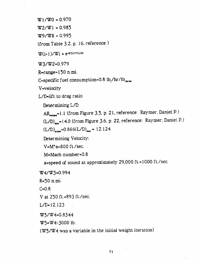
W I/W0 _, 0.970
W2/WI = 0.985
W9/W8 = O.995
(from Table 3.2, p. 16, reference )
W(i+ I )/Wi = e -r_(cv'L>_)
W3/W2=0.979
R-range= 150 n.mi.
C=specific fuel consumption=0.8 Ibrlhr/Ib_.,t
V=velocity
LID-,lift to drag ratio
Determining L/D:
AR_,=I.I (from Figure 3.5, p. 21, reference: Raymer, Daniel P.)
(L/D),,,,,14.0 (from Figure 3.6, p. 22, reference: Raymer, Daniel P.)
(LID)=_.,,=O.866(L/D),,,,= 12.124
Determining Velocity:
V=M*a=800 ft./sec.
MffiMach number=0.8
a=speed of sound at approximately 29,000 ft.= 1000 ft./sec.
W4/W3=0.994
R=50 n.mi.
C=0.8
V at 250 ft.=893 ft./sec.
L/D=I2.123
W5/W4=0.8344
W5=W4-3000 lb.
(W5/W4 was a variable in the initial weight iteration)
71

W6/W5= I -C*(T/W)*d=0.982
T/W=thrust to weight ratio= 1.0 (assumed)
Determining d:
d=time duration at maximum power=(2*pi*Vx)/(g*(n2_ I))
n=load factor=6.5
x=number of turns=3
V=Velocity=893 ft./sec.
g=gravity=32.2 ft./sec2
W7/W6=W4/W3=0.994
W8/W7=W3/W2=0.979
Ill Takeoff Gross Weight
W9/Wo=(W9/W8 )*(W8/W7)*(W7/W6 ),(W6/WS ).(WS/W4)
*(W4/W3)*(W3/W2 )*(W2/W i )*(W I/W0 )=0.74292
Fuel Fraction Estimation: Wt/Wo= 1.05"( I -W9/Wo)
Wt=fuel weight
Payload=2 pilots+2 sidewinder missiles+ I machine gun+6 bombs
=2*(225 Ib.)+2"(200 Ib.)+450 lb.+3000 Ib.=4300 lb.
Wo=W +WWe=Payload Weight
Dividing by Wo: I=Wr/Wo+W/Wo+Wp/Wo=I.05, (I-W9/Wo)+
1.989"Wo-O,3 +4300/Wo
Wo=4300/( I-W9/Wo-(1.989"Wo-0,3))
Iterating, Wo=24,111 lb.
IV Fuel Weight
W_=Wo-Wg-W_,
Wt=24111-17545.5-3000=3565.5 Ib t
72

Component Weight Calculations
W
wing
. • * * 0.5* 0.6"*A0#ss*(t/c)_od °4W._=0.0103 K,, K_ (W_ N,) Sv
•CI +X)°-°_*CcosCA))- 1.0*S_ °4
K_=constant= 1.0 for non-delta wing
K =constant=l.0 for non-delta wing
W_=design gross weight=24111 lb.
N =ultimate Load factor= 1.5*limit load factor= 1.5*6.50=9.75
S, =trapezoidal wing area= 190 ft.'
A=aspect ratio=2.7
(tlc)_=thickness ratio at root=0.06
X=tip to root ratio=0.23
A=wing sweep at 25% MAC=44 degrees
S=,=control surface (wing mounted)=25 ft.'
=757.6 II).f
II Horizontal Tail
W_,. ,.,,=3.316"( l +Fv/Bh)-z°* ((W,,* N,) / 1000 )o26o,Sht08o6
F, =fuselage width at horizontal tail intersection=2 ft.
Bh=horizontal tail span= 13 ft.
Sh=horizontal tail area=65 ft. 2
W_,,,,,,=297.882 lbt.
Ill Vertical Tail
1___/_ ;os*_'W *N/o_***S o_**M °.3_'*L_'°*W_.,,t.,1=0.452*K_*(,_,,,-',v1 , _ ,'
( I +SIS,,) °3'**A_° m* CI +x)o.25"(cosCA_))-o 323
73

K,,,=constant= 1.0
_/H_=0.0 for conventional tail
M=Mach number=0.8
Lt=tail length=22.8 in.
St=rudder area=7.83 in._
S,_=vertical tail area=33.6 in.2
A_=vertical tail area=1.0 in.z
_.=tip to root ratio=0.23
A_=vertical tail sweep=50 deg.
W,_,,.,= I 01.32 Ib c.
IV Fuselage
W_q.=0.499*K_*W0.J3*N,025*L o_*DoS,_*W0.6_
K_=constant= 1.0 for non-delta wing aircraft
L-fuselage structural length=45 ft.
D-fuselage structural depth=5 ft.
W-fuselage structural width=5 ft.
Wfuselage= 1351 Ib r
V Main Landing Gear
Kd,=constant= 1.0 for non-cross-beam gear
K,_=constant= I. 0
W1=landing design gross weight= 17890 Ibf.
N1=ultimate landing load factor=5.5
L,.=length of main landing gear=48 in.
W,w_=765.75 Ib c.
74
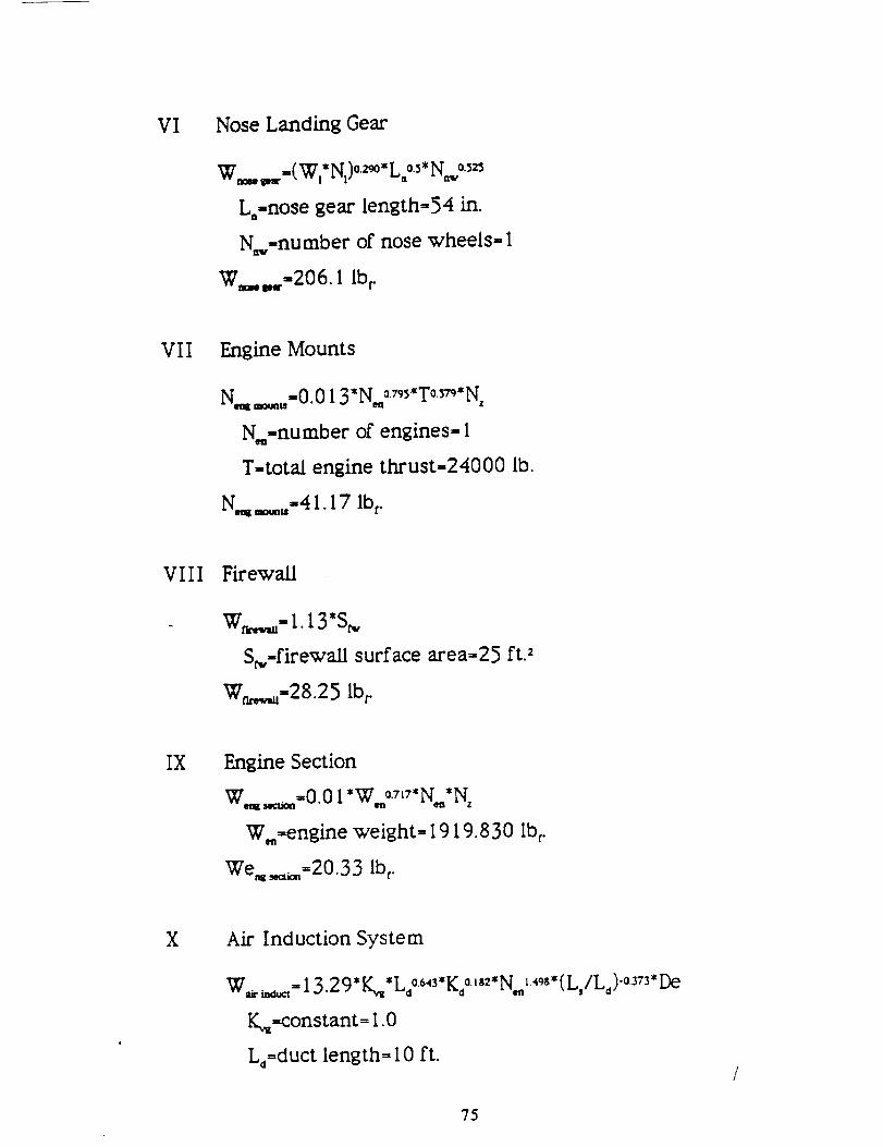
Vl Nose Landing Gear
W_= _., =(Wl*Ni)°29°*Ln°.5.No._
Lo=nose gear length=54 in.
N_,=number of nose wheels= I
W_._=206. IIb r
VII Engine Mounts
Nq _,.=0.013*N._o._*T°.3_* Nz
N.,=number of engines= I
T=total engine thrust=24000 lb.
N._ _=,.=4 I. 17 Ib r.
VIII Firewall
W_= I. 13"S_,
S_,=firewaU surface area=25 ft. 2
W_,_=28.25 Ib t.
IX Engine Section
Wq_=0.01 *W. o.71_*N,*Nz
W._=engine weight= 1919.830 Ib_.
We_,==20.33 Ibm.
X Air Induction System
W_ _= 13.2 9" K_*Ld°643"KdQ_8_*N.__498.(L,/L_)-o3_3"De
K_=constant= 1.0
Ld=duct length= I0 ft.
75

Kd=2.6
L,=3 ft.
Do,.engine diameter=46.068 in.
W_ _=418.12 Ibm.
XI Engine Cooling
Wq =_=4.55*Do*L,_*N,_
L,_=length of engine shroud= 12.5 ft.
Wq=_=255.9 Ib_
XII Oil Cooling
W_=_=37.82*Nm ,.°_
W_=_=37.82 Ibm.
XIII Engine Controls
Wq =at=10.5 *N,_L.°°8*L,_°_
L_=length from engine front to cockpit= 150.008 ft.
Wq=_=3.04 Ib r.
XIV Starter (Pneumatic)
W,_=0.025 *T°o.76o,N_._
T°=thrust per engine=24000 lb.
W,_=53.32 Ibm.
XV Fuel System and Tanks
Wt_, _=7.45" Vto_*( I +(V_/Vt))-oog_*(I +(VJV_) )*N_oo_* N_o-o52
*((T*SFC)/1000)o_9
76
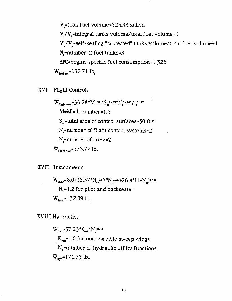
V,=total fuel volu me=52 4.3 4 gallon
Vl/Vt=integral tanks volu me/total fuel volu me= I
VJV,=self-sealing "protected" tanks volume/total fuel volu me= 1
Nt=number of fuel tanks=3
SFC=engine specific fuel consumption= 1.526
W_,=697.71 Ibt.
XVI Flight Controls
W,_ ==t-36.28" Mo0o3"S=o.,89,No.4_4,Noo,_
M=Mach number= 1.5
S==total area of control surfaces=50 ft2
N,=number of flight control systems=2
No=number of crew=2
W_=m=375.77 Ib t.
XVll Instruments
Ww,=8.0+36.37*N, 0.676"No._+26.4"( 1+N_), _
N_= 1.2 for pilot and backseater
W_=132.09 Ib r.
XVIII Hydraulics
W_,=37.2 3" K_*N..06_
K_= 1.0 for non-variable sweep wings
N_=nu mber of hydraulic utility functions
W,_= 171.75 Ib t.
77

XIX Electrical
W_= 172.2*K_*R_°-_5_*Nc°1°*La°I°*Ng,_°°9_
K_= 1.45 since mission completion required after failure
R_=syste m electrical r ating=50 kv* A
L =electrical routing distance=30 ft.
N =number of generators= I
W_,,=68 1.49 Ibm.
XX
XXI
Avionics
W_==2.117"W_ °.9_33
W =uninstaUed avionics weight= 1 I00 Ibf.
W,_== 1456.6 Ibf.
Furnishings
Wf_=217.6"No
Wf_=435.2 Ib t.
XXII Air Conditioning and Anti-lce
W==201.6"((W_+ 20 0*N_)/1000)o.735
W==302.4 Ib t.
XXI I I Handling Gear
W_d =3.2x I 0-4*W_,
W_ =7.716 Ibf.
78
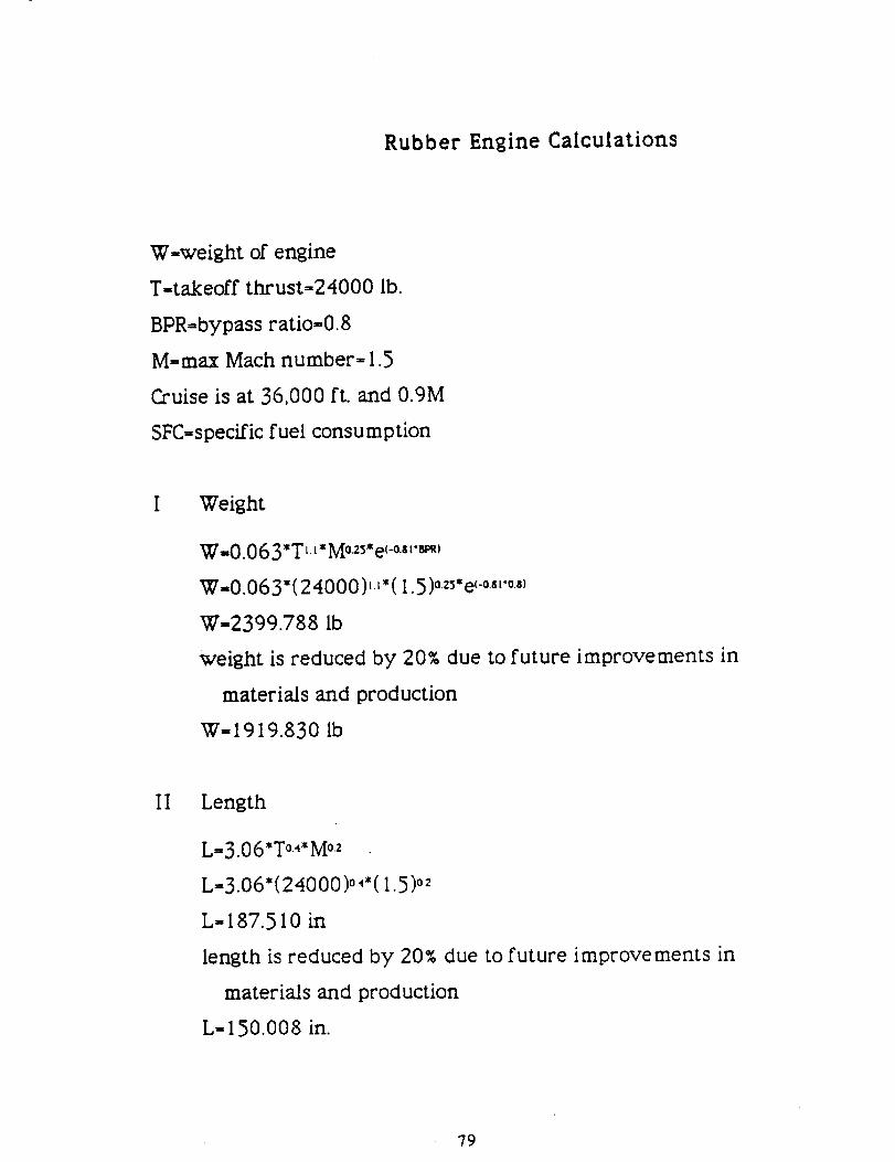
Rubber Engine Calculations
W=weight of engine
T=takeoff thrust=24000 lb.
BPR=bypass ratio=0.8
M=max Mach number= 1.5
Cruise is at 36,000 ft. and 0.9M
SFC=specific fuel consumption
! Weight
W=O.063*T t.1*Mo.25,e(-o.sl,_)
W=O.O 63*( 24000 )_t ,( I. 5 )°_5"e (-°.8_'°,8)
W=2399.788 Ib
weight is reduced by 20% due to future improvements in
materials and production
W=1919.830 Ib
II Length
L=3.06*T °-4.M°-2
L=3.06"( 24000 )°.4,( I. 5 )o2
L=187.510 in
length is reduced by 20% due to future improvements in
materials and production
L= 150.008 in.
79

III Diameter
D=0.288*T0.5*e(0.04*BPR)
D=0.288*(24000)0.5*e(0.04*0.8)
D=46.068 in.
IV Specific Fuel Consumption for Maximum Thrust
SFC...r=2. I *e(-o.,='_)
SFC...r=2. I *e(-o.12.os)
SFC...r= 1.908 Ibc./hr./Ib_,.,
specific fuel consumption for maximum thrust is reduced by
20% due to future improvements in materials and production
SFC=ur- 1.526 Ibt_/hr./Ib_,u, '
V Specific Fuel Consumption for Cruise
SFC_. - 1.04"_-o ,86.B_)
SFC=.=,= 1.04"_-o.,86.o,)
SFC_=,=0.896
specific fuel consumption for cruise is reduced by 20% due to
future improvements in materials and production
SFC=..=0.717 Ibf_lhr.llb,=.,
VI Thrust for Cruise
T=== I. 6" T °.74* e(o°z3._R)
T=.,. = 1.6 *(24000 )o74"e_oo23"o8)
T_L,.=28 40.974 Ib t
g0

Component Sizing
Fuselage
L..... =A*W_LimWlil_Jw i)
Lfuselage=length of fuselage
A=constant=0.93 for jet fighter
Wo=gross takeoff weight=24111 Ibr.
C-constant=0.39 for jet fighter
Lrw_,=47.5 ft.
Fineness ratio=L_w_,/d,., t_,i_,
d_,r_,w=maximum diameter of fuselage=4.9 ft.
Fineness ratio=9.7
II Vertical Tail
S,_-(C_*b,,*S,,)/L,_
S_=planform area of vertical tail
C_=vertical tail volu me coefficient=0.07 for jet fighter
b,,=wing span=31.0 ft.
Sv=planform area of wing=353.5 ft.
L_=length from quarter-chord of wing to quarter-chord or" tail
=22.8 ft.
S,,=33.6 ft. 2
81

III Horizontal Tail
S,,-(C_*C,*S,,)/L,,
S,,-planform area of horizontal tail
Ch,=horizontal tail coefficient=0.40 for jet fighter
C_=wing chord-I 1.0 ft.
L_-length from quarter-chord of wing to quarter-chord of tail
-22.8 ft.
SW.68.2 ft.2
horizontal tail area was reduced by 15% due to variable pitch
thrust inherent to ST0VL aircraft
S,-57.97 ft.2
82

Determination of Lift and Drag Coefficients
=sumCr=flat plate skin friction
FF=form factor
a-interference factor
S,_-wetted area
S,t=reference area
Subscript c represents individual component, i.e., fuselage,
wing, etc.
II C_= (0.45 5/( (log,0R)zs"*( I +0.144"M2)0.65) _ Turbulent
R=Reynolds nu mber=(p* V*l)/u
M=Mach number
III Form Factor
Wing, Pylon, and Strut
FF = [I +0.6/((x/c)m)*(t/c)+ 100*(t/c)4]*[ 1.3 4" Mo.,8*(cos(A)m)o28]
xlc=location of maxi mum airfoil thickness/chor d=0.4
tic=thickness to chord ratio=0.0 6
A=leading edge sweepback angle
Fuselage and Smooth Canopy
FF= 1+60/f3+f/400
t=I/ d=I/( ( 4/n )*A_)o.5
l=component length
d=component diameter
83

Inlet
IrF,,I+(d/l)
MisceUaneous drags
These values were determined from a graph.
IV Supersonic Drag
CD- F._*[ 1-0.386"(M= 1.2)0-_*( I -((II*AL)?-_)]*(D/q)
E_=empirical wave drag= 1.0
DIq=9*H/2* (A,,_/I) 2
V Total CD
CD_,=d ,, CL_/q*S
CL=LIq*S which was done for M=0. I to M=1.5 and altitude
sea level to 35,000 feet
q= 1/2" p'v2
Vl Drag
Drag=C_*q*S
84

Cost Calculations
H.=engineering hours
I_=tooling hours
H.=manufacturing hours
H_=quality control
Ho=4.86*(empty weight)0.777*(velocity)0.894*(aircraft quantity)0.163
HT=5.99*( empty weight )0.777*(velocity )0.696 *( quantity )0.263
H.=7.37*(empty weight)0.82*(velocity)0.484*(quantity)0.641
H_=0.133*( manufacturing hours)
Develop ment=CD= 45.42*(empty weight)0.630* (velocity) 1.3
Flight test costs=Cy= 1243.03*(empty weight)0.325*(velocity)0.822
*(# test vehicles) 1.21
Materials cost=CM= I 1.0*(empty weight)0.or2 l*(velocity)0.621
*(quantity)0.799
i'=average annual inflation rate
f=market interest rate
i'=( I +i)/( I +f)- I
Cost90 =Cost86*( I / I+0.0271 )4
Cost90=Cost86*( I. I 1324)
85