Literature Data and Corrosion Testing of Hard Anodized …a-mcpt.com/SAEAeroTechConfPaper.pdf ·...
8
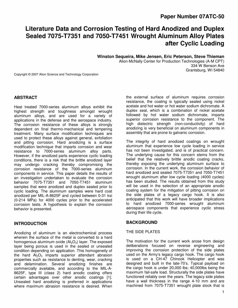
1 Paper Number 07ATC-50 Literature Data and Corrosion Testing of Hard Anodized and Duplex Sealed 7075-T7351 and 7050-T7451 Wrought Aluminum Alloy Plates after Cyclic Loading Winston Sequeira, Mike Jensen, Eric Peterson, Steve Thieman Alion-McNally Center for Production Technologies (A-M CPT) 334 W Benson Ave Grantsburg, WI 54840 Copyright © 2007 Alion Science and Technology Corporation ABSTRACT Heat treated 7000-series aluminum alloys exhibit the highest strength and toughness amongst wrought aluminum alloys, and are used for a variety of applications in the defense and the aerospace industry. The corrosion resistance of these alloys is strongly dependent on final thermo-mechanical and tempering treatment. Many surface modification techniques are used to protect these alloys against general, exfoliation and pitting corrosion. Hard anodizing is a surface modification technique that imparts corrosion and wear resistance to 7000-series aluminum alloy parts. However, if the anodized parts experience cyclic loading conditions, there is a risk that the brittle anodized layer may undergo cracking thereby compromising the corrosion resistance of the 7000-series aluminum components in service. This paper details the results of an investigation undertaken to evaluate the corrosion behavior 7075-T7351 and 7050-T7451 aluminum samples that were anodized and duplex sealed prior to cyclic loading. The aluminum samples were hard coat anodized per MIL-A-8625F and cycled between 0-31 ksi (0-214 MPa) for 4000 cycles prior to the accelerated corrosion tests. A hypothesis to explain the corrosion behavior is presented. INTRODUCTION Anodizing of aluminum is an electrochemical process wherein the surface of the metal is converted to a hard homogenous aluminum oxide (Al 2 O 3 ) layer. The exposed layer being porous is used in the sealed or unsealed condition depending on application. This homogeneity of the hard Al 2 O 3 imparts superior attendant abrasion properties such as resistance to denting, wear, cracking and delamination. Several anodizing finishes are commercially available, and according to the MIL-A- 8625F, type III (class 2) hard anodic coating offers certain advantages over other anodic coatings [1]. Unsealed hard anodizing is preferred in applications where maximum abrasion resistance is desired. When the external surface of aluminum requires corrosion resistance, the coating is typically sealed using nickel acetate and hot water or hot water sodium dichromate. A duplex seal, which is a combination of nickel acetate followed by hot water sodium dichromate, imparts superior corrosion resistance to the component. The high dielectric strength (non-conductivity) of hard anodizing is very beneficial on aluminum components in assembly that are prone to galvanic corrosion. The integrity of hard anodized coatings on wrought aluminum that experience low cycle loading in service has not been investigated, and is of practical concern. The underlying cause for this concern stems from the belief that the relatively brittle anodic coating cracks, thereby exposing the underlying aluminum surface to corrosion. In the current work, the corrosion behavior of hard anodized and sealed 7075-T7351 and 7050-T7451 wrought aluminum after low cycle loading (4000 cycles) has been studied. The results obtained from this study will be used in the selection of an appropriate anodic coating system for the mitigation of pitting corrosion on the side plates of a legacy cargo hook. It is also anticipated that this work will have broader implications to hard anodized 7000-series wrought aluminum aerospace components that experience cyclic stress during their life cycle. BACKGROUND THE SIDE PLATES The motivation for the current work arose from design deliberations focused on reverse engineering and improving the corrosion protection of the side plates used on the Army’s legacy cargo hook. The cargo hook is used on a CH-47 Chinook Helicopter and was designed and built in the late-70’s. Typical payload on the cargo hook is under 20,000 lbs; 40,000lbs being the maximum fail-safe load. Structurally the side plates have functioned reliably over the years. The legacy side plates have a wall thickness in the range 4-10 mm and are machined from 7075-T7351 wrought plate stock that is
Transcript of Literature Data and Corrosion Testing of Hard Anodized …a-mcpt.com/SAEAeroTechConfPaper.pdf ·...
1
Paper Number 07ATC-50
Literature Data and Corrosion Testing of Hard Anodized and Duplex Sealed 7075-T7351 and 7050-T7451 Wrought Aluminum Alloy Plates
after Cyclic Loading
Winston Sequeira, Mike Jensen, Eric Peterson, Steve Thieman Alion-McNally Center for Production Technologies (A-M CPT)
334 W Benson Ave Grantsburg, WI 54840
Copyright © 2007 Alion Science and Technology Corporation
ABSTRACT
Heat treated 7000-series aluminum alloys exhibit the highest strength and toughness amongst wrought aluminum alloys, and are used for a variety of applications in the defense and the aerospace industry. The corrosion resistance of these alloys is strongly dependent on final thermo-mechanical and tempering treatment. Many surface modification techniques are used to protect these alloys against general, exfoliation and pitting corrosion. Hard anodizing is a surface modification technique that imparts corrosion and wear resistance to 7000-series aluminum alloy parts. However, if the anodized parts experience cyclic loading conditions, there is a risk that the brittle anodized layer may undergo cracking thereby compromising the corrosion resistance of the 7000-series aluminum components in service. This paper details the results of an investigation undertaken to evaluate the corrosion behavior 7075-T7351 and 7050-T7451 aluminum samples that were anodized and duplex sealed prior to cyclic loading. The aluminum samples were hard coat anodized per MIL-A-8625F and cycled between 0-31 ksi (0-214 MPa) for 4000 cycles prior to the accelerated corrosion tests. A hypothesis to explain the corrosion behavior is presented.
INTRODUCTION
Anodizing of aluminum is an electrochemical process wherein the surface of the metal is converted to a hard homogenous aluminum oxide (Al2O3) layer. The exposed layer being porous is used in the sealed or unsealed condition depending on application. This homogeneity of the hard Al2O3 imparts superior attendant abrasion properties such as resistance to denting, wear, cracking and delamination. Several anodizing finishes are commercially available, and according to the MIL-A-8625F, type III (class 2) hard anodic coating offers certain advantages over other anodic coatings [1]. Unsealed hard anodizing is preferred in applications where maximum abrasion resistance is desired. When
the external surface of aluminum requires corrosion resistance, the coating is typically sealed using nickel acetate and hot water or hot water sodium dichromate. A duplex seal, which is a combination of nickel acetate followed by hot water sodium dichromate, imparts superior corrosion resistance to the component. The high dielectric strength (non-conductivity) of hard anodizing is very beneficial on aluminum components in assembly that are prone to galvanic corrosion. The integrity of hard anodized coatings on wrought aluminum that experience low cycle loading in service has not been investigated, and is of practical concern. The underlying cause for this concern stems from the belief that the relatively brittle anodic coating cracks, thereby exposing the underlying aluminum surface to corrosion. In the current work, the corrosion behavior of hard anodized and sealed 7075-T7351 and 7050-T7451 wrought aluminum after low cycle loading (4000 cycles) has been studied. The results obtained from this study will be used in the selection of an appropriate anodic coating system for the mitigation of pitting corrosion on the side plates of a legacy cargo hook. It is also anticipated that this work will have broader implications to hard anodized 7000-series wrought aluminum aerospace components that experience cyclic stress during their life cycle. BACKGROUND
THE SIDE PLATES
The motivation for the current work arose from design deliberations focused on reverse engineering and improving the corrosion protection of the side plates used on the Army’s legacy cargo hook. The cargo hook is used on a CH-47 Chinook Helicopter and was designed and built in the late-70’s. Typical payload on the cargo hook is under 20,000 lbs; 40,000lbs being the maximum fail-safe load. Structurally the side plates have functioned reliably over the years. The legacy side plates have a wall thickness in the range 4-10 mm and are machined from 7075-T7351 wrought plate stock that is
2
equivalent to AMS 4078 [2]. They are then anodized before assembly.
(a)
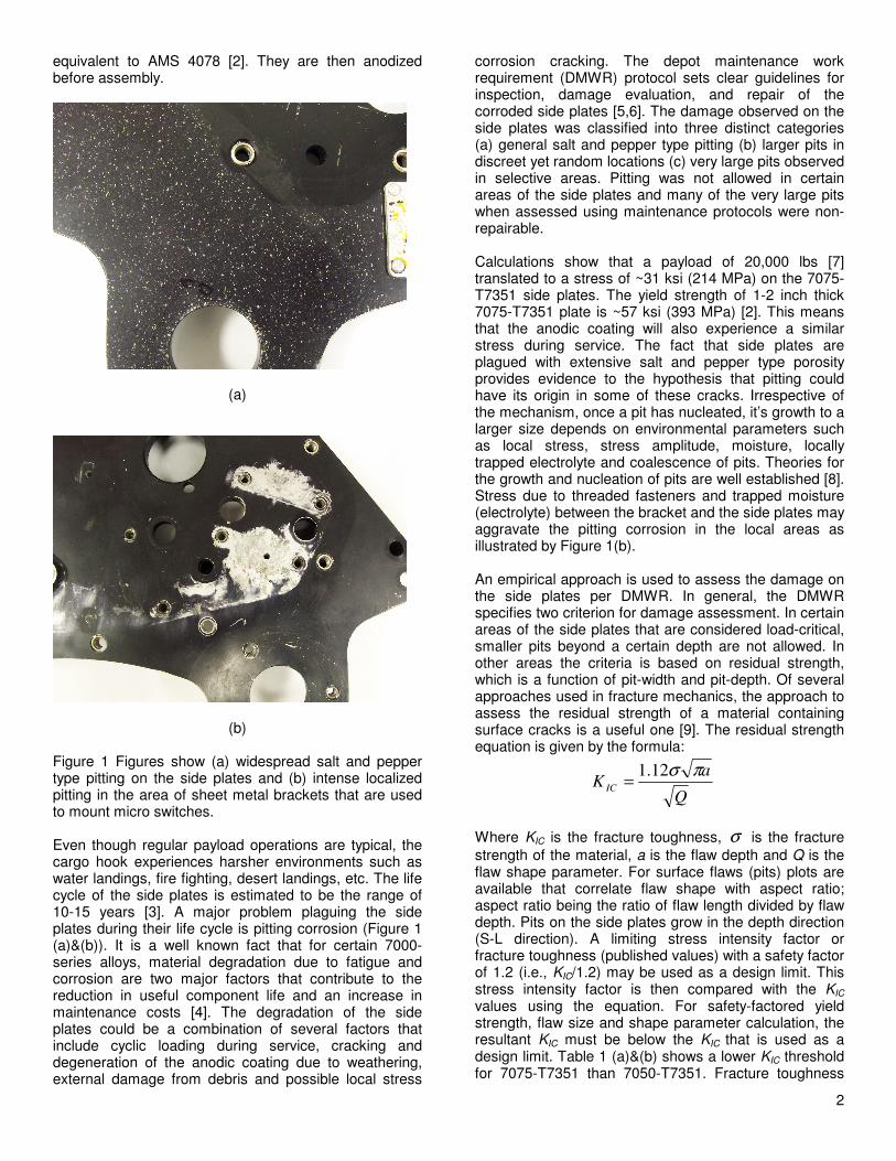
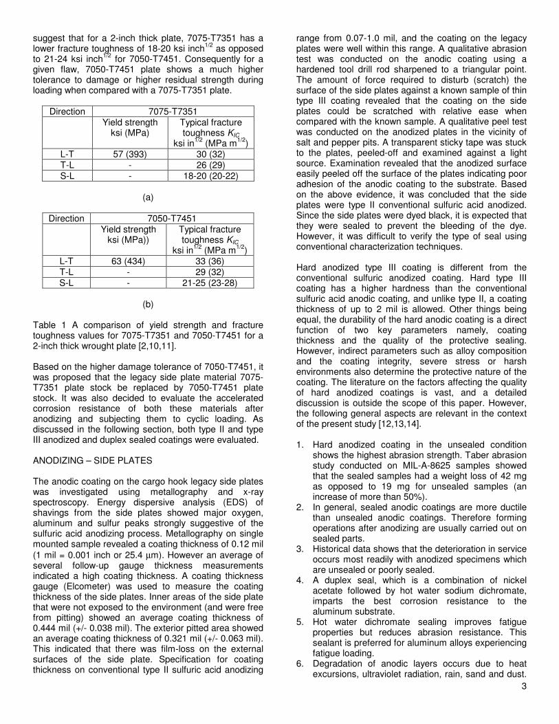
(b) Figure 1 Figures show (a) widespread salt and pepper type pitting on the side plates and (b) intense localized pitting in the area of sheet metal brackets that are used to mount micro switches. Even though regular payload operations are typical, the cargo hook experiences harsher environments such as water landings, fire fighting, desert landings, etc. The life cycle of the side plates is estimated to be the range of 10-15 years [3]. A major problem plaguing the side plates during their life cycle is pitting corrosion (Figure 1 (a)&(b)). It is a well known fact that for certain 7000-series alloys, material degradation due to fatigue and corrosion are two major factors that contribute to the reduction in useful component life and an increase in maintenance costs [4]. The degradation of the side plates could be a combination of several factors that include cyclic loading during service, cracking and degeneration of the anodic coating due to weathering, external damage from debris and possible local stress
corrosion cracking. The depot maintenance work requirement (DMWR) protocol sets clear guidelines for inspection, damage evaluation, and repair of the corroded side plates [5,6]. The damage observed on the side plates was classified into three distinct categories (a) general salt and pepper type pitting (b) larger pits in discreet yet random locations (c) very large pits observed in selective areas. Pitting was not allowed in certain areas of the side plates and many of the very large pits when assessed using maintenance protocols were non-repairable. Calculations show that a payload of 20,000 lbs [7] translated to a stress of ~31 ksi (214 MPa) on the 7075-T7351 side plates. The yield strength of 1-2 inch thick 7075-T7351 plate is ~57 ksi (393 MPa) [2]. This means that the anodic coating will also experience a similar stress during service. The fact that side plates are plagued with extensive salt and pepper type porosity provides evidence to the hypothesis that pitting could have its origin in some of these cracks. Irrespective of the mechanism, once a pit has nucleated, it’s growth to a larger size depends on environmental parameters such as local stress, stress amplitude, moisture, locally trapped electrolyte and coalescence of pits. Theories for the growth and nucleation of pits are well established [8]. Stress due to threaded fasteners and trapped moisture (electrolyte) between the bracket and the side plates may aggravate the pitting corrosion in the local areas as illustrated by Figure 1(b). An empirical approach is used to assess the damage on the side plates per DMWR. In general, the DMWR specifies two criterion for damage assessment. In certain areas of the side plates that are considered load-critical, smaller pits beyond a certain depth are not allowed. In other areas the criteria is based on residual strength, which is a function of pit-width and pit-depth. Of several approaches used in fracture mechanics, the approach to assess the residual strength of a material containing surface cracks is a useful one [9]. The residual strength equation is given by the formula:
Q
aK
IC
πσ12.1=
Where KIC is the fracture toughness, σ is the fracture
strength of the material, a is the flaw depth and Q is the flaw shape parameter. For surface flaws (pits) plots are available that correlate flaw shape with aspect ratio; aspect ratio being the ratio of flaw length divided by flaw depth. Pits on the side plates grow in the depth direction (S-L direction). A limiting stress intensity factor or fracture toughness (published values) with a safety factor of 1.2 (i.e., KIC/1.2) may be used as a design limit. This stress intensity factor is then compared with the KIC values using the equation. For safety-factored yield strength, flaw size and shape parameter calculation, the resultant KIC must be below the KIC that is used as a design limit. Table 1 (a)&(b) shows a lower KIC threshold for 7075-T7351 than 7050-T7351. Fracture toughness
3
suggest that for a 2-inch thick plate, 7075-T7351 has a lower fracture toughness of 18-20 ksi inch
1/2 as opposed
to 21-24 ksi inch1/2
for 7050-T7451. Consequently for a given flaw, 7050-T7451 plate shows a much higher tolerance to damage or higher residual strength during loading when compared with a 7075-T7351 plate.
Direction 7075-T7351 Yield strength
ksi (MPa) Typical fracture toughness KIC
ksi in1/2
(MPa m1/2
) L-T 57 (393) 30 (32) T-L - 26 (29) S-L - 18-20 (20-22)
(a)
Direction 7050-T7451
Yield strength ksi (MPa))
Typical fracture toughness KIC
ksi in1/2
(MPa m1/2
) L-T 63 (434) 33 (36) T-L - 29 (32) S-L - 21-25 (23-28)
(b)
Table 1 A comparison of yield strength and fracture toughness values for 7075-T7351 and 7050-T7451 for a 2-inch thick wrought plate [2,10,11]. Based on the higher damage tolerance of 7050-T7451, it was proposed that the legacy side plate material 7075-T7351 plate stock be replaced by 7050-T7451 plate stock. It was also decided to evaluate the accelerated corrosion resistance of both these materials after anodizing and subjecting them to cyclic loading. As discussed in the following section, both type II and type III anodized and duplex sealed coatings were evaluated. ANODIZING – SIDE PLATES The anodic coating on the cargo hook legacy side plates was investigated using metallography and x-ray spectroscopy. Energy dispersive analysis (EDS) of shavings from the side plates showed major oxygen, aluminum and sulfur peaks strongly suggestive of the sulfuric acid anodizing process. Metallography on single mounted sample revealed a coating thickness of 0.12 mil
(1 mil = 0.001 inch or 25.4 µm). However an average of several follow-up gauge thickness measurements indicated a high coating thickness. A coating thickness gauge (Elcometer) was used to measure the coating thickness of the side plates. Inner areas of the side plate that were not exposed to the environment (and were free from pitting) showed an average coating thickness of 0.444 mil (+/- 0.038 mil). The exterior pitted area showed an average coating thickness of 0.321 mil (+/- 0.063 mil). This indicated that there was film-loss on the external surfaces of the side plate. Specification for coating thickness on conventional type II sulfuric acid anodizing
range from 0.07-1.0 mil, and the coating on the legacy plates were well within this range. A qualitative abrasion test was conducted on the anodic coating using a hardened tool drill rod sharpened to a triangular point. The amount of force required to disturb (scratch) the surface of the side plates against a known sample of thin type III coating revealed that the coating on the side plates could be scratched with relative ease when compared with the known sample. A qualitative peel test was conducted on the anodized plates in the vicinity of salt and pepper pits. A transparent sticky tape was stuck to the plates, peeled-off and examined against a light source. Examination revealed that the anodized surface easily peeled off the surface of the plates indicating poor adhesion of the anodic coating to the substrate. Based on the above evidence, it was concluded that the side plates were type II conventional sulfuric acid anodized. Since the side plates were dyed black, it is expected that they were sealed to prevent the bleeding of the dye. However, it was difficult to verify the type of seal using conventional characterization techniques. Hard anodized type III coating is different from the conventional sulfuric anodized coating. Hard type III coating has a higher hardness than the conventional sulfuric acid anodic coating, and unlike type II, a coating thickness of up to 2 mil is allowed. Other things being equal, the durability of the hard anodic coating is a direct function of two key parameters namely, coating thickness and the quality of the protective sealing. However, indirect parameters such as alloy composition and the coating integrity, severe stress or harsh environments also determine the protective nature of the coating. The literature on the factors affecting the quality of hard anodized coatings is vast, and a detailed discussion is outside the scope of this paper. However, the following general aspects are relevant in the context of the present study [12,13,14]. 1. Hard anodized coating in the unsealed condition
shows the highest abrasion strength. Taber abrasion study conducted on MIL-A-8625 samples showed that the sealed samples had a weight loss of 42 mg as opposed to 19 mg for unsealed samples (an increase of more than 50%).
2. In general, sealed anodic coatings are more ductile than unsealed anodic coatings. Therefore forming operations after anodizing are usually carried out on sealed parts.
3. Historical data shows that the deterioration in service occurs most readily with anodized specimens which are unsealed or poorly sealed.
4. A duplex seal, which is a combination of nickel acetate followed by hot water sodium dichromate, imparts the best corrosion resistance to the aluminum substrate.
5. Hot water dichromate sealing improves fatigue properties but reduces abrasion resistance. This sealant is preferred for aluminum alloys experiencing fatigue loading.
6. Degradation of anodic layers occurs due to heat excursions, ultraviolet radiation, rain, sand and dust.
4
Also, film thickness loss occurs with long term exposure.
7. In general, pitting attack represents long-term deterioration of an anodic coating and is confined to the weak sites in the coating which are randomly distributed. Pitting has been found to be more dependent on the alloy and anodic film thickness than on sealing quality. Second phase and intermetallic particles in an alloy may be anodized inadequately representing areas of weakness in the coating. There is no published data that suggests cracks caused due to strain in anodic coatings result in weak sites.
For 7000-series wrought alloys, there is some data suggesting that the anodizing coating cracks during loading. However, little has been published in the area of correlating cracked anodic coatings and pitting corrosion in 7000-series wrought alloys. Pitting has been observed in anodized and constant amplitude loaded 7010-T7651 alloy [15]. It has been reported that in the high cycle fatigue, the fatigue endurance limit of anodized aluminum alloys decreased by up to ~ 20% when compared to non-anodized parts [12,16]. This reduction in fatigue endurance limit has been attributed to the formation of cracks, which act as stress risers [16]. A recent Ohio State University (OSU) study investigated the cracking of three different anodized coatings thickness on 7050-T74 alloy used on landing gears [17]. Acoustic emission technique was used to gather evidence of cracking of the anodized layers ranging from 0.1 mil to 0.8 mil, and strain values for cracking of coatings were evaluated. Results indicate that for thicker coatings, the cracking event started at a higher strain than thinner coatings. Extensive cracking was observed in the stress range of 140-400 MPa for coating thickness in the range 0.2-0.8 mil. This stress level was well below the yield stress of the tensile specimens which was ~460 MPa. It has also been shown that cracking and delamination occur in commercial coatings, and that the cracking occurs at stress levels lower than the yield strength of the substrate material [18,19]. It is clear from the above that cracking of the anodized coating may have a strong influence on the pitting corrosion. More importantly, the extent to which sealed coatings subjected to cyclic loading conditions resist pitting corrosion during long duration environmental exposure is unknown. ASTM B117 salt fog test is a prolonged exposure test that could be used to validate the durability of the anodized coating. Of particular interest to this study are anodic coatings of ~0.5 mil. Per MIL-A-8625F, ~0.5 mil coating thickness requires radii of 0.015 inch and ~1 mil a 0.030 inch radii. A smaller radii on the side plates was preferable to reduce machining costs, even though an anodic coating thickness in the range 1-2 mil may be considered beneficial in terms of corrosion protection. The present study is expected to provide insight to the following. 1. With cyclic load being approximately 50% of the
yield stress, will the 7000-series samples cycled
between 0 and 31 ksi perform differently in accelerated salt tests when compared with regular samples that are not subjected to cyclic loading?
2. For the same coating thickness, is there a difference in corrosion resistance between 7075-T7351 and 7050-T7451 samples that are type II and type III anodized and duplex sealed (both load-cycled and regular samples)?
3. Will all the samples, inclusive of cyclic stressed anodized samples, exceed the MIL-A-8625F specifications of 336 hours of salt spray testing? In addition, how will the samples perform if the salt spray tests were extended to 400 hours?
EXPERIMENTAL WORK A number of flat tensile samples conforming to ASTM B557 [20] were machined from 7075-T7351 and 7050-T7451 wrought plate stock material. The material conformed to AMS 4078 and AMS 4050 respectively, and samples were machined from 2-inch flat plates. After machining, the gauge surface area had a surface finish of 15-20 Ra. The samples were sulfuric acid (type II) and hard coat (type III) anodized per MIL-A-8625F at Spec Plating, Minneapolis. The material matrix is shown in Table 2. The samples were class 2 dyed, and were duplex sealed with nickel acetate followed by hot water sodium dichromate. Coating thickness measurements were carried out using Elcometer model 465. The coating thickness and coating thickness variations are listed in Table 2. The coating measurements are based on the eddy current measurement principle consistent with ASTM B224 [21]. The coating thickness was in the range 0.3 mil to 0.6 mil; coating variations were within the +/-20% range as specified in MIL-A-8625F. Material and
type of coating
Coating thickness in mil
(1 mil =25.4 µm)
Cyclic load
testing
Regular samples (non load cycled)
7050-T7451 type II
0.618 (+/- 0.062)
4 4
7050-T7451 type III
0.552 (+/-0.082)
4 4
7075-T7351 type II
0.521 (+/-0.036)
4 4
7075-T7351 type III
0.304 (+/-0.045)
4 4
Table 2 Anodic coating type and thickness used on 7075-T7451 and 7050-T7351 tensile samples that were subjected to corrosion testing. Only half the samples (four) in each group listed in Table 2 were subjected to uniaxial cyclic loading between a load of 0 and 6050 lbs. Based on the cross-section of the samples in the gauge area, the load of 6050 lbs translated to ~31 ksi. This is the overall stress
5
experienced by the assembled side plates when subjected to a load of 20,000 lbs. The stress was equivalent to ~54% of the yield stress for 2-inch thick 7075-T7351 material. The cyclic load tests were carried out using a fully instrumented MTS 810 Material Testing System. A sinusoidal loading-unloading pattern was used during the cyclic load tests, and the allowable load tolerance limits were +/- 20 lbs. A wave frequency was 1.5 Hz (90 cycles/minute). This low frequency was used to prevent heating of the samples due to internal friction. After cyclic testing, the damaged (dimpled) grip areas of the samples were sealed using epoxy glue and allowed to set for 24 hours. Both load cycled and regular samples were weighed and placed in pallets for salt fog testing in accordance with ASTM B117 [22]. The samples were aligned so that the flat faces were at approximately 30 degrees to the horizontal (pallet). The samples were oriented in this manner to allow the salt mist to run-off the sample. Cleaning, weight change measurements were carried in accordance with the procedure described in ASTM G1-03 [23]. The samples were dried in an oven for an hour at 100
oF prior to weight change measurements. Weight
change measurements were carried out after exposure times of 48, 96, 166, 350 and 400 hours. During weight loss measurements, the samples were examined visually all around the grip area for evidence of pitting and then photographed. RESULTS AND DISCUSSION The distribution of pits on the external surface of the side plates lead to the conclusion that pitting on the 7075-T7351 plates may have its origins in the weak sites of the type II anodic coating. Scratch and peel tests on the legacy side plates indicate that degradation of the anodic coating may have occurred due to long-term exposure to the environment (or weathering). Before considering type III hard anodic coating, it was crucial to evaluate if the cracking of the anodic coating played a role in pit initiation. The results obtained for both type II and type III duplex anodic coatings are discussed. Published literature indicates that in forming operations on anodized parts, cracking occurs when elongation reaches a value of ~0.5% (Since sealed anodic coatings show higher ductility, it is assumed that these anodic coatings were sealed). However, for thicker coatings, elongation values of anodic films are reported to average 0.3-0.4% [12]. An examination of typical stress strain curves for 7050-T74 tensile samples indicates that a load of ~31 ksi is equivalent to ~50% of the yield strength of the alloy, and recently concluded work at OSU has shown that for hard anodized and dichromate sealed anodic coating, cracking occurs in the strain range 0.2-0.6% for coating thickness 0.2-0.8 mil [17]. This study confirms previously reported strain ranges for cracking of anodic coatings. From typical stress strain curves for
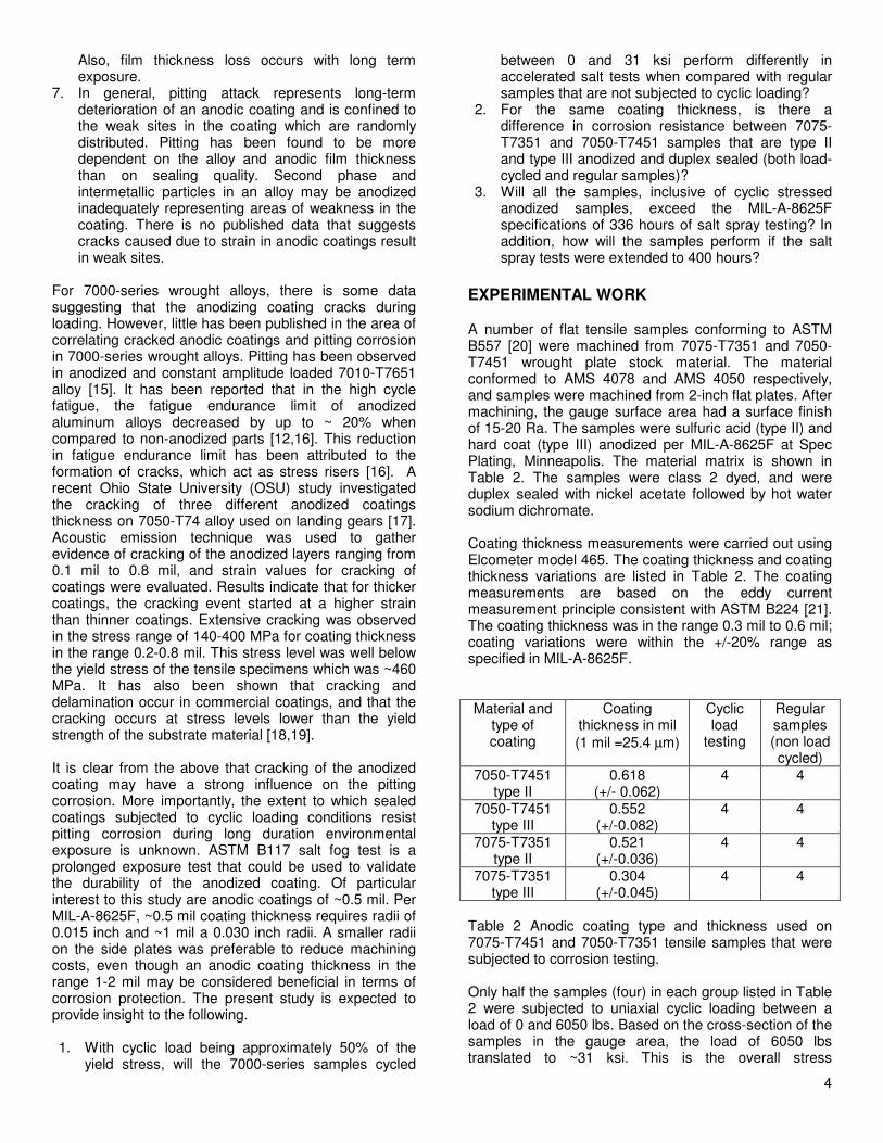
7050-T74 material, the strain range of 0.2-0.6% translates to a stress level in the range 20-58 ksi (140-400 MPa). The testing of anodized specimens in this study is carried out at ~31 ksi (214 MPa), and on the basis of published data it is clear that the coating will undergo damage due to cyclic loading. However, as discussed later, the cracking tendency of a duplex sealed anodic coating appears to play a crucial role in limiting the pitting corrosion on aluminum alloys. The weight change measurements on all the samples, and observation of pitting corrosion on tensile samples yielded positive results. Figure 2 shows the change in weight of the tensile specimens with salt fog exposure time for load cycled samples. The results shown are variations in weight of a single sample for each alloy-coating combination, and the trend is similar for all four specimens tested across each group. These results indicate that there are no statistical variations in weight change of the samples with exposure time. Weight change results were similar for regular specimens (Figure 3) that were not subjected to load cycles. When one compares specimens from the same lot in Figure 2 & 3, there is a discrepancy in the initial weight of the specimens. This is because the trend in weight change for only one specimen is plotted, and the initial weight of the tensile specimens within each lot varied somewhat.
94.2000
94.4000
94.6000
94.8000
95.0000
95.2000
95.4000
95.6000
95.8000
96.0000
96.2000
0 48 96 166 350 400
Hours of exposure (hours)
Ch
an
ge i
n w
eig
ht
(gra
ms)
7075, type II, 0.521 mil
7075, type III, 0.304 mil
7050, type II, 0.618 mil
7050, type III, 0.552 mil
Figure 2 Variation of weight change with exposure time for load-cycled specimens with type II and type III coatings.
92.5000
93.0000
93.5000
94.0000
94.5000
95.0000
95.5000
0 48 96 166 350 400
Hours of exposure (hours)
Ch
an
ge
in
we
igh
t (g
ram
s)
7075, type II, 0.521 mil
7075, type III, 0.304 mil
7050, type II, 0.618 mil
7050, type III, 0.552 mil
6
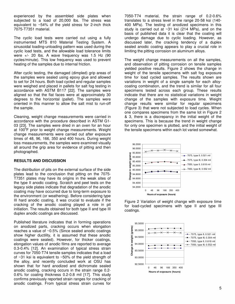
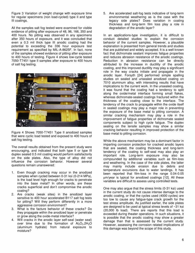
Figure 3 Variation of weight change with exposure time for regular specimens (non load-cycled) type II and type III coatings. All the samples salt fog tested were examined for visible evidence of pitting after exposure of 48, 96, 166, 350 and 400 hours. No pitting was observed in any specimens after 350 hours of exposure, and it was concluded that even a 0.3 mil thick type III anodic coating had the potential to exceeding the 336 hour exposure test requirement as specified by MIL-A-8625F. In fact, none of the samples showed evidence of pitting after exposure to 400 hours of testing. Figure 4 shows low-cycle tested 7050-T7451 type II samples after exposure to 400 hours of salt fog testing.
Figure 4 Shows 7050-T7451 Type II anodized samples that were cyclic load tested and exposed to 400 hours of salt fog testing. The overall results obtained from the present study were encouraging, and indicated that both type II or type III duplex sealed 0.5 mil coating would perform satisfactorily on the side plates. Also, the type of alloy did not influence the corrosion behavior. However several questions remain unanswered: 1. Even though cracking may occur in the anodized
samples when cycled between 0-31 ksi (0-214 MPa), is the load level high enough for cracks to penetrate into the base metal? In other words, are these cracks superficial and don’t compromise the anodic coating?
2. Are cracks (weak sites) in the anodized layer sensitive to 400 hour accelerated B117 salt fog tests for pitting? Will they perform differently in a more aggressive corrosion environment?
3. What is the facture behavior of these cracks? Do they propagate within the anodized layer or penetrate or grow along the oxide-metal interface?
4. Will cracks in the anodic layer self-seal (water seal) over time due to the formation of Al2O3.2H2O (aluminum hydrate) from natural exposure to moisture?
5. Are accelerated salt-fog tests indicative of long-term environmental weathering as is the case with the legacy side plates? Does variation in coating thickness and long-term film loss play a role in degradation of the anodic layer?
In an applications-type investigation, it is difficult to conduct detailed studies to explain the corrosion behavior of the current samples. However, a plausible explanation is presented from general trends and studies that are published and widely accepted. It is a well known fact that dichromate sealant improves fatigue properties and reduces abrasion resistance of the anodic coatings. Reduction in abrasion resistance can be directly attributed to the increase in ductility of the anodic coating, and this improved ductility may play a significant role in the way cracks initiate and propagate in the anodic layer. Forsyth [24] performed simple spalling studies on sealed and unsealed anodized coating on 7010 aluminum alloy, with interesting results that have implications to the current work. In the unsealed coating, it was found that the coating had a tendency to split along the oxide/metal interface forming small flakes, whereas dichromate-sealed coatings fractured within the thickness of the coating close to the interface. The tendency of the crack to propagate within the oxide itself in sealed coatings may play a major role in preventing the exposure of the base metal to pitting corrosion. A similar cracking mechanism may play a role in the improvement of fatigue properties of dichromate sealed components subject to high cycle fatigue. The duplex sealing on the tensile samples may show a similar cracking behavior resulting in improved protection of the base metal to pitting corrosion. While the above mechanism may be a dominant factor in imparting corrosion protection for cracked anodic layers that are sealed, the coating thickness and long-term tendency of the coating to self-seal may also play an important role. Long-term exposure may also be compounded by additional variables such as film-loss and weathering. In the case of the side plates, the latter may mainly include erosion due to debris and temperature excursions due to water landings. It has been reported that film-loss in the range 0.04-0.05
µm/year is typical for anodized coatings [12]. All these variables are difficult to assess using controlled tests. One may also argue that the stress limits (0-31 ksi) used in the current study do not cause intense damage to the anodic coating, or that the cycles used (4000 cycles) are too low to cause any fatigue-type crack growth for the test stress amplitude. As justified earlier, the side plates are designed to be used at typical stress levels of ~31 ksi (20,000 lb load). There are reports that this load is exceeded during theater operations. In such situations, it is possible that the anodic coating may show a greater damage than that is assessed by the current study. However, assessing the corrosion related implications of this damage was beyond the scope of this study.
7
There could be minor differences in the cracking of type II anodic coating due to the variation in Al2O3
morphology, pore size and lower hardness when compared to type III anodic coating. However, as evident in the current study, these don’t appear to be significant in causing pitting damage. As far as the side plates are concerned, it was determined that type III duplex sealed coating would provide a higher level of protection against long-term environmental exposure and weathering (debris) than type II duplex coating of an equivalent coating thickness. CONCLUSION 1. The pitting on the 7075-T7351 legacy side plates of
a cargo hook was investigated. It was determined that the coating was a type II anodic coating. The coating was found to be in poor condition.
2. Low cycle, load tested duplex coated type II and type III of thickness ~ 0.5 mil showed outstanding corrosion protection when subjected to accelerated corrosion tests. The coating exceeded 400 hours of continuous exposure, and showed no signs of weight loss or pitting corrosion. All the coatings and alloys tested in this study showed this same good performance.
3. It was hypothesized that the way cracks propagate within sealed anodic coating has a major influence on the corrosion behavior. Sealed coatings crack within the coating and to a lesser extent at the coating-metal interface. This cracking mode does not expose the metal surface to corrosion and therefore prevents the development of pits.
4. Because of its higher hardness, it was concluded that a type III coating thickness of ~0.5 mil that is duplex sealed is advantages over a similar type II coating in harsher weathering environments.
5. Based on the analysis of literature data and results from corrosion testing it was recommended that ~0.5 mil thick type III duplex sealed anodized 7050-T7451 alloy be implemented for the forward and aft Cargo Hook side plates.
ACKNOWLEDGEMENT This effort was funded by the United States Army under contract number W31P4Q-05-C-0242. Alion Science and Technology, and the authors of this paper would like to thank and acknowledge the support of Scott Hofacker and Jamie White, Manufacturing Science and Technology Division (Redstone Arsenal, AL), Mark Dyer, Cargo Hook Project Office, Redstone Arsenal, and Victor Armstrong III, OLR Ft Lewis, WA, and their colleagues for continued support on this project.
REFERENCES 1. MIL-A-8625F, Anodic Coatings for Aluminum and Aluminum Alloys, Revision F, 10 September 1993.
2. AMS 4078F, Aluminum Alloy Plate 7075-T7351 Solution Heat Treated, Stress Relieved and Overaged, Revised February 2008, SAE, Warrendale, PA. 3. Private communication, Armstrong III, Victor Y CIV USA USAMC, OLR Fort Lewis, WA, 3 April 2007. 4. Connoly.B.J, Defffenbaugh.K.L, Koul.M.G, Moran.A.L, Environmentally Assisted Crack Growth Rates of High Strength Aluminum Alloys, Journal of Metals, January 2003. 5. Wesselschmidt, Matt, AMSRD-AMR-AE-C Memorandum for SFAE-AV-CH, Subject: Review Damage Repair Criterion for Forward and Aft Cargo Hooks, TTS 15252, dated 27 June 2004. 6. Hayden, Rex, Memorandum for AMCOM Project OLR, Damage Limits and Repair Criteria for CH-47 Forward and Aft Cargo Hook Side Plates, dated 22 March 2006. 7. Boeing Vertol Company, Philadelphia, Control document # DAAJ01-76-6-0653, dated 13 June 1977. 8. Fontana.M.G, Corrosion Engineering, McGraw-Hill International Edition, 1987. 9. Timmins.P.F, Operating Stress Maps for Failure Control, ASM Handbook Vol 19, Fatigue and Fracture, p457-467, 1996, ASM Materials Park, OH. 10. AMS 4050H, Aluminum Alloy Plate 7050-T7451 Solution Heat Treated, Stress Relieved and Overaged, Revised December 2003, SAE, Warrendale, PA. 11. Alcoa Aluminum Alloy 7050, Alcoa Center, PA, 1985. 12. Wernick.S, Pinner.R, Sheasby.P.G, The Surface Treatment and Finishing of Aluminum and its Alloys, Sixth Edition, 2001, Finishing Publications Ltd., Trowbridge, UK. 13. Alina.W, Tribological Synergistic Coatings, Coating Technology Handbook, Ed. Donatas.S, Arthur.A.T, p299-311, Marcel Dekker, 2000. 14. Snogan.F, Blanc.C, Mankowski.G, Pebere.N, Characterization of Sealed Anodic Films on 7050T74 and 2214T6 Aluminum Alloys, Surface and Coatings Technology, 154, p94-103, 2002. 15. Crawford.B.R, Loader.C, Ward.A.R, Urbani.C, Bache.M.R, Spence.S.H, Hay.D.G, Evans.W.J, Clark.G, Stonham.A.J, The EIFS Distribution for Anodized and Pre-Corroded 7010-T7651 Under Constant Amplitude Loading, Fatigue Fracture Engg. Mater. Struct., 28, p795-808, 2005. 16. AMS Handbook Vol. 5, Surface Engineering, 1999, ASM Materials Park, OH. 17. Goetz.J.M, Investigation of Coating Cracking and Fatigue Strength of 7050-T74 Aluminum Alloy with Different Anodized Coating Thicknesses, BS Honors Thesis, Ohio State University, 2005. 18. Thouless.M.D, Cracking and Delamination of Coatings, J. Vac. Sci. Technol. A9, 4, July-Aug, 1991. 19. Chen.B.F, Hwang.J, Huang.J.H, In-situ Observations of the Cracking Behavior of TiN Coating on 304 Stainless Steel Subject to Tensile Strain, Thin Solid Films 353, p173-178, 1999. 20. ASTM B557-06, Standard Test Methods for Tension Testing Wrought and Cast Aluminum and Magnesium Alloy Products, ASTM International, PA. 21. ASTM B224-97, Standard Test Method for Measurement of Thickness of Anodic Coatings on Aluminum and other Nonconductive Coatings on
8
Nonmagnetic basis Metals with Eddy Current Instruments, ASTM International, PA. 22. ASTM B117-03, Standard Practice for Operating Salt Spray (Fog) Apparatus, ASTM International, PA. 23. ASTM G1-03, Standard Practice for Preparing, Cleaning and Evaluating Corrosion Test Specimens, ASTM International, PA. 24. Forsyth.P.J.E, Thick Anodically Formed Oxide Coatings on High Strength Aluminum Alloys, Their Fracture Behavior in the Vicinity of the Oxide/Metal Interface, Material Letters 29, p45-55, 1996.