ListMyPolygons 0.6
14
University Of Manchester School of Physics and Astronomy Object-Oriented Programming in C++ Project Report ListMyPolygons Author: Riccardo WIlliam Monfardini Student ID: 7484334 October 29, 2013
-
Upload
riccardo-w-monfardini -
Category
Documents
-
view
87 -
download
0
Transcript of ListMyPolygons 0.6
University Of Manchester
School of Physics and Astronomy
Object-Oriented Programming in C++ ProjectReport
ListMyPolygons
Author:
Riccardo WIlliam Monfardini
Student ID: 7484334
October 29, 2013
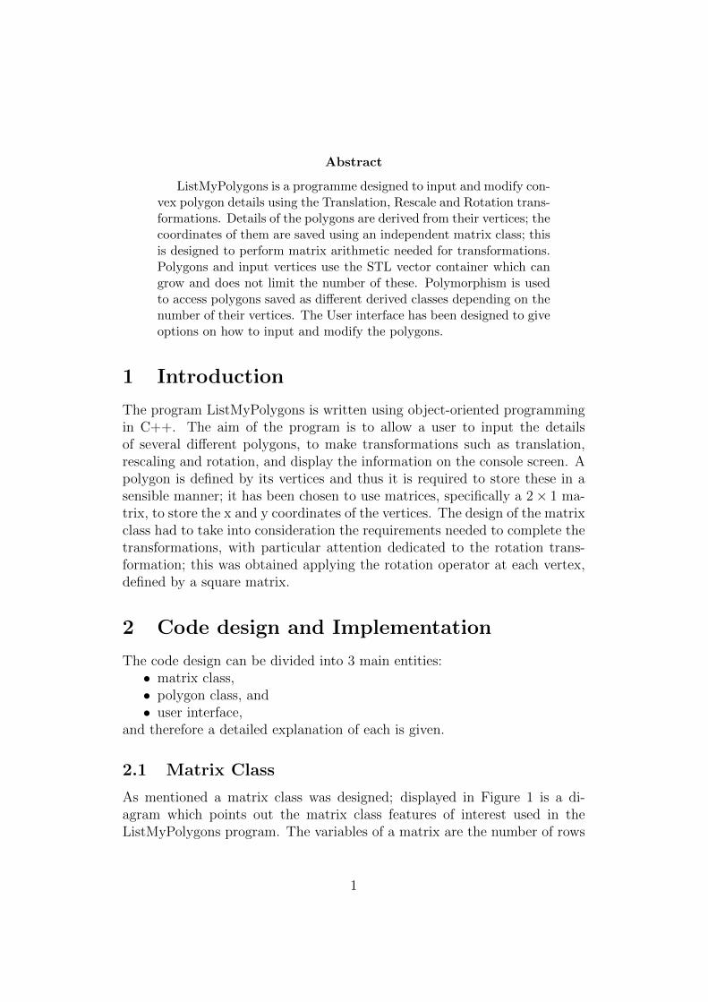
Abstract
ListMyPolygons is a programme designed to input and modify con-vex polygon details using the Translation, Rescale and Rotation trans-formations. Details of the polygons are derived from their vertices; thecoordinates of them are saved using an independent matrix class; thisis designed to perform matrix arithmetic needed for transformations.Polygons and input vertices use the STL vector container which cangrow and does not limit the number of these. Polymorphism is usedto access polygons saved as different derived classes depending on thenumber of their vertices. The User interface has been designed to giveoptions on how to input and modify the polygons.
1 Introduction
The program ListMyPolygons is written using object-oriented programmingin C++. The aim of the program is to allow a user to input the detailsof several different polygons, to make transformations such as translation,rescaling and rotation, and display the information on the console screen. Apolygon is defined by its vertices and thus it is required to store these in asensible manner; it has been chosen to use matrices, specifically a 2 × 1 ma-trix, to store the x and y coordinates of the vertices. The design of the matrixclass had to take into consideration the requirements needed to complete thetransformations, with particular attention dedicated to the rotation trans-formation; this was obtained applying the rotation operator at each vertex,defined by a square matrix.
2 Code design and Implementation
The code design can be divided into 3 main entities:• matrix class,• polygon class, and• user interface,
and therefore a detailed explanation of each is given.
2.1 Matrix Class
As mentioned a matrix class was designed; displayed in Figure 1 is a di-agram which points out the matrix class features of interest used in theListMyPolygons program. The variables of a matrix are the number of rows
1
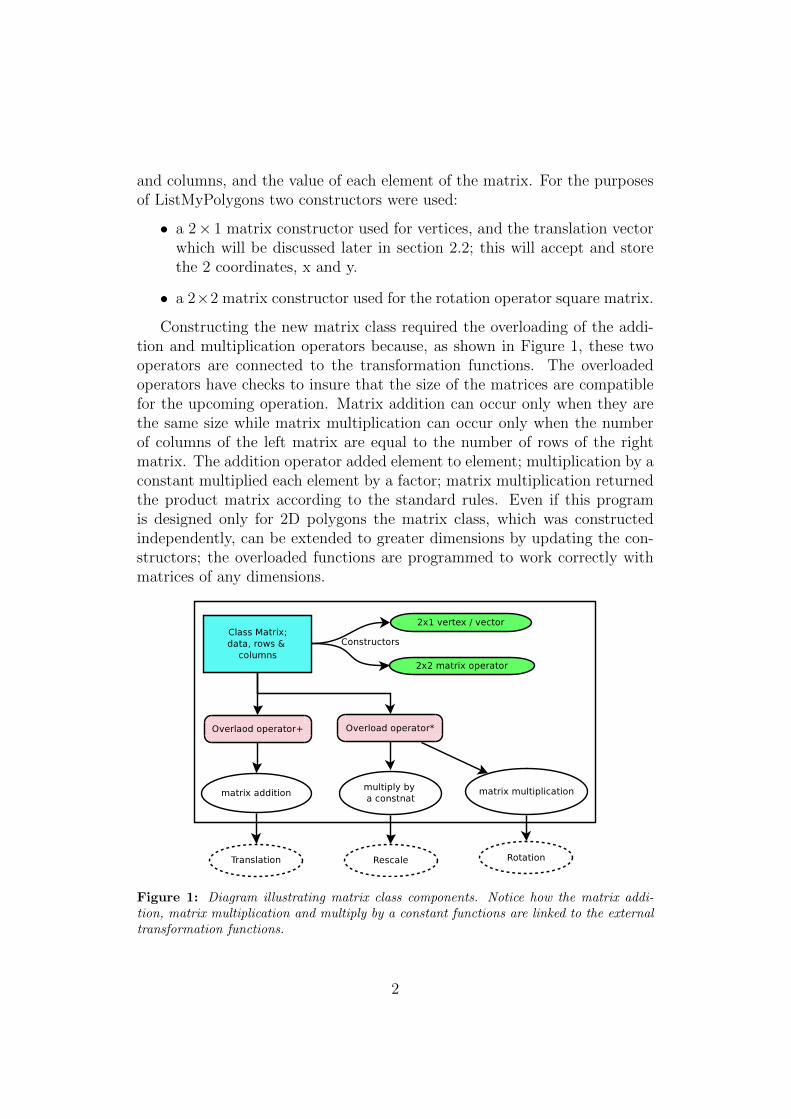
and columns, and the value of each element of the matrix. For the purposesof ListMyPolygons two constructors were used:
• a 2× 1 matrix constructor used for vertices, and the translation vectorwhich will be discussed later in section 2.2; this will accept and storethe 2 coordinates, x and y.
• a 2×2 matrix constructor used for the rotation operator square matrix.
Constructing the new matrix class required the overloading of the addi-tion and multiplication operators because, as shown in Figure 1, these twooperators are connected to the transformation functions. The overloadedoperators have checks to insure that the size of the matrices are compatiblefor the upcoming operation. Matrix addition can occur only when they arethe same size while matrix multiplication can occur only when the numberof columns of the left matrix are equal to the number of rows of the rightmatrix. The addition operator added element to element; multiplication by aconstant multiplied each element by a factor; matrix multiplication returnedthe product matrix according to the standard rules. Even if this programis designed only for 2D polygons the matrix class, which was constructedindependently, can be extended to greater dimensions by updating the con-structors; the overloaded functions are programmed to work correctly withmatrices of any dimensions.
Figure 1: Diagram illustrating matrix class components. Notice how the matrix addi-tion, matrix multiplication and multiply by a constant functions are linked to the externaltransformation functions.
2
2.2 Polygon Class
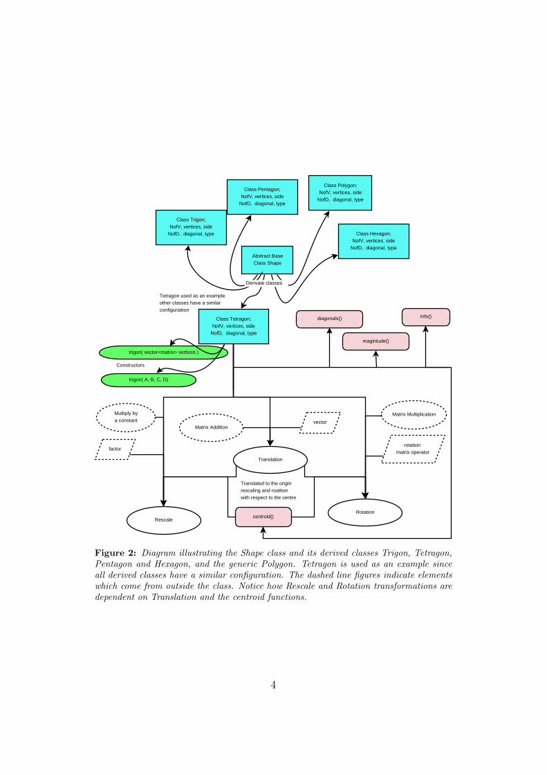
The second main entity in the design of ListMyPolygons is the polygon classitself. Figure 2 shows a schematic representation of the design of this entity.An abstract class named shape was designed to be the parent of all possiblepolygons. From this, 5 derived classes were defined: trigon, tetragon, pen-tagon, hexagon, and a generic polygon . The use of an abstract class allowsthe exploitation of the polymorphism feature of object oriented C++: theabstract class can be used as pointer to access the functions of the derivedclasses which are defined with the same name.
Because the derived polygon classes all had similar functions, only aschematic representation of the tetragon class is shown in Figure 2. Thepolygons can be constructed in 2 ways: with the individual matrix of eachvertex or the std::vector container formed by vertex matrices. The con-structor determined the values of the other parameters: the arrays side anddiagonal were determined by the difference between vertices. They used twofunctions:
• diagonals, which return the number of possible diagonals (NofD) giventhe number of vertices (NofV), and
• magnitude, which returned the magnitude of a vector, a row matrix.
An exception is made for the polygon class. Used as a class for polygons withmore than 6 vertices, it can only be constructed by a vector of matrices; thisallows the program to define NofV by its size. Thanks to this informationthe type of polygon is found, such as Isosceles Triangle, Rectangle, IrregularHexagon, Irregular Polygon etc. Regular polygons are determined as well, forexample Equilateral Triangle, Regular Pentagon etc.; however these polygonswere found to be unreliable, as is discussed in section 3. The function infois designed to output the details of the polygon onto the console screen forthe user to review.
The complex feature of these classes is the transformation functions,Translation, Rescale and Rotation. As illustrated by Figure 2 Rescale andRotation are dependent on Translation and the function centroid. Transla-tion uses a 2 × 1 matrix vector which is added to each vertex thanks to thematrix addition discussed previously. Rescale and Rotation, however, have tobe performed with respect to a point or axis. Thus, before performing thesetransformations, the polygon centre, found through the centroid function, istranslated to the origin. At this point the vertices are rescaled or rotated bymultiplying by a factor or the rotation matrix operator respectively. Finallythe polygons are translated back to their original position.
3
Abstract BaseClass Shape
Class Trigon;NofV, vertices, side
NofD, diagonal, type
Class Tetragon;NofV, vertices, side
NofD, diagonal, type
Class Pentagon;NofV, vertices, side
NofD, diagonal, type
Class Polygon;NofV, vertices, side
NofD, diagonal, type
trigon( A, B, C, D)
trigon( vector<matrix> vertices )
diagonals()
centroid()
Translation
Rotation
Rescale
vectorMatrix Addition
Multiply bya constant
Matrix Multiplication
factorrotation
matrix operator
Constructors
Translated to the originrescaling and roattionwith respect to the centre
Tetragon used as an exampleother classes have a similar configuraition
info()
magintude()
Class Hexagon;NofV, vertices, side
NofD, diagonal, type
Derivate classes
Figure 2: Diagram illustrating the Shape class and its derived classes Trigon, Tetragon,Pentagon and Hexagon, and the generic Polygon. Tetragon is used as an example sinceall derived classes have a similar configuration. The dashed line figures indicate elementswhich come from outside the class. Notice how Rescale and Rotation transformations aredependent on Translation and the centroid functions.
4
2.3 User Interface
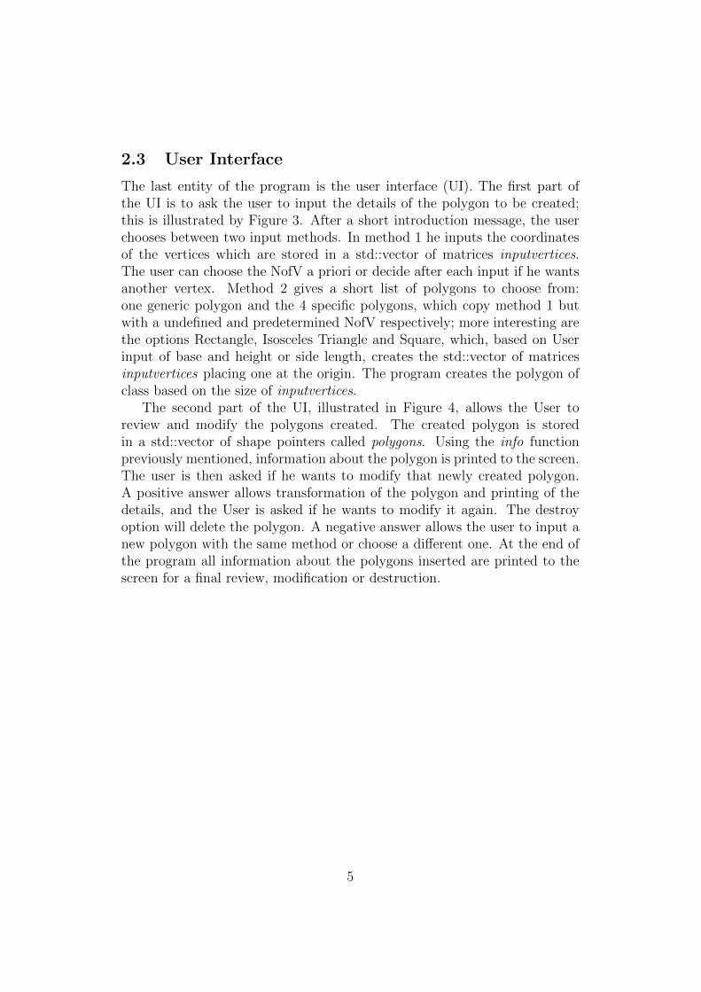
The last entity of the program is the user interface (UI). The first part ofthe UI is to ask the user to input the details of the polygon to be created;this is illustrated by Figure 3. After a short introduction message, the userchooses between two input methods. In method 1 he inputs the coordinatesof the vertices which are stored in a std::vector of matrices inputvertices.The user can choose the NofV a priori or decide after each input if he wantsanother vertex. Method 2 gives a short list of polygons to choose from:one generic polygon and the 4 specific polygons, which copy method 1 butwith a undefined and predetermined NofV respectively; more interesting arethe options Rectangle, Isosceles Triangle and Square, which, based on Userinput of base and height or side length, creates the std::vector of matricesinputvertices placing one at the origin. The program creates the polygon ofclass based on the size of inputvertices.
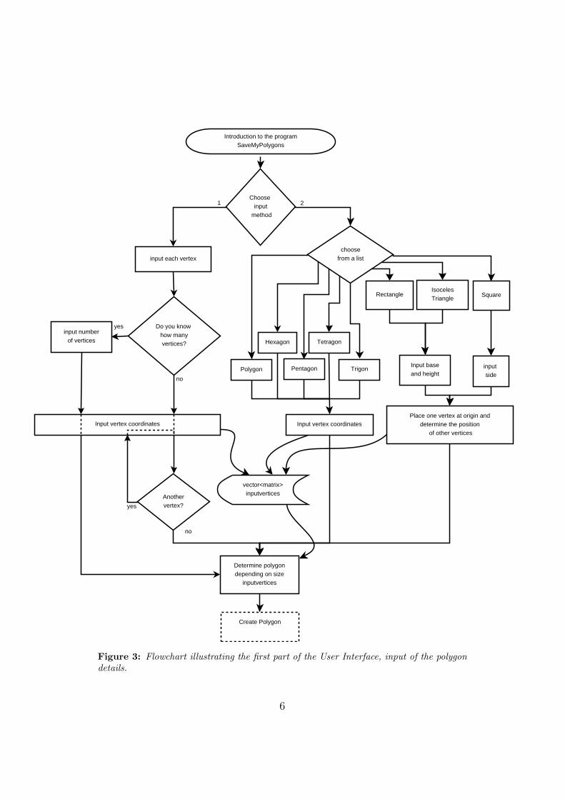
The second part of the UI, illustrated in Figure 4, allows the User toreview and modify the polygons created. The created polygon is storedin a std::vector of shape pointers called polygons. Using the info functionpreviously mentioned, information about the polygon is printed to the screen.The user is then asked if he wants to modify that newly created polygon.A positive answer allows transformation of the polygon and printing of thedetails, and the User is asked if he wants to modify it again. The destroyoption will delete the polygon. A negative answer allows the user to input anew polygon with the same method or choose a different one. At the end ofthe program all information about the polygons inserted are printed to thescreen for a final review, modification or destruction.
5
Introduction to the programSaveMyPolygons
Choose input
method
input each vertex
Do you know how manyvertices?
Input vertex coordinates
Anothervertex?
IsocelesTriangle
choosefrom a list
SquareRectangle
Pentagon
Hexagon
yes
vector<matrix>inputvertices
Determine polygondepending on size
inputvertices
input numberof vertices
Input vertex coordinates
Create Polygon
Input baseand height
input side
Place one vertex at origin anddetermine the position
of other vertices
no
1 2
no
yes
Trigon
Tetragon
Polygon
Figure 3: Flowchart illustrating the first part of the User Interface, input of the polygondetails.
6
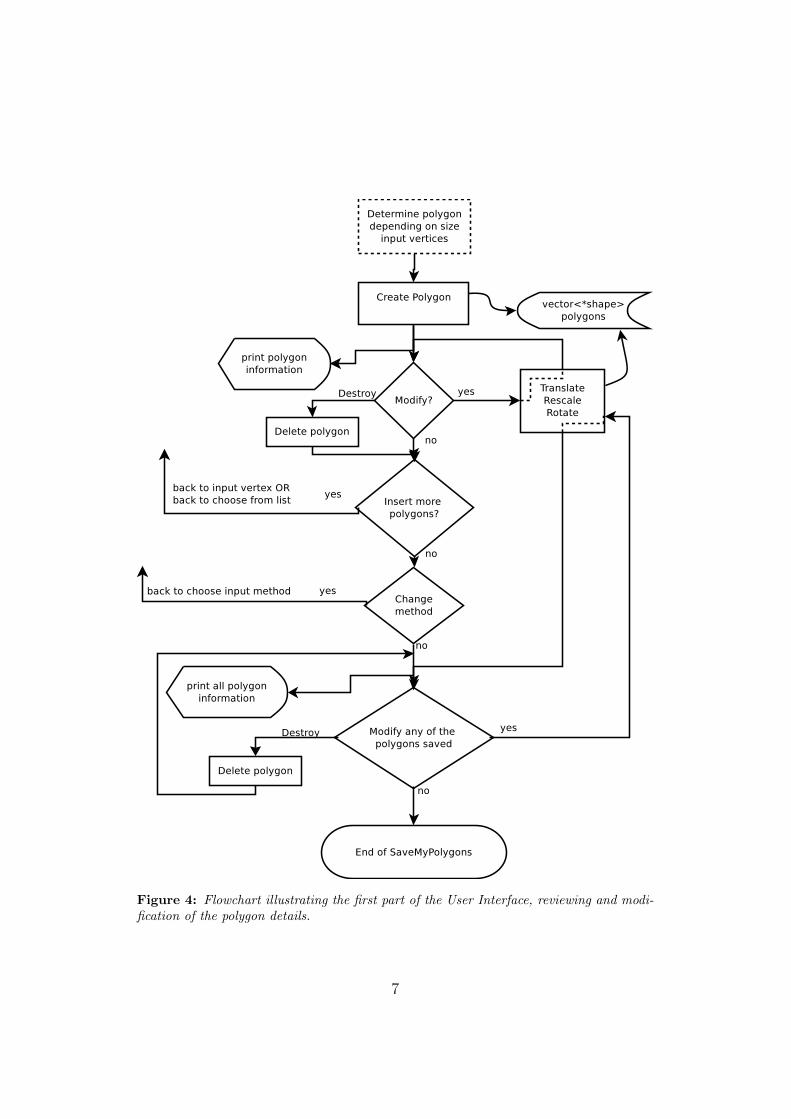
Figure 4: Flowchart illustrating the first part of the User Interface, reviewing and modi-fication of the polygon details.
7
3 Results & Limitations
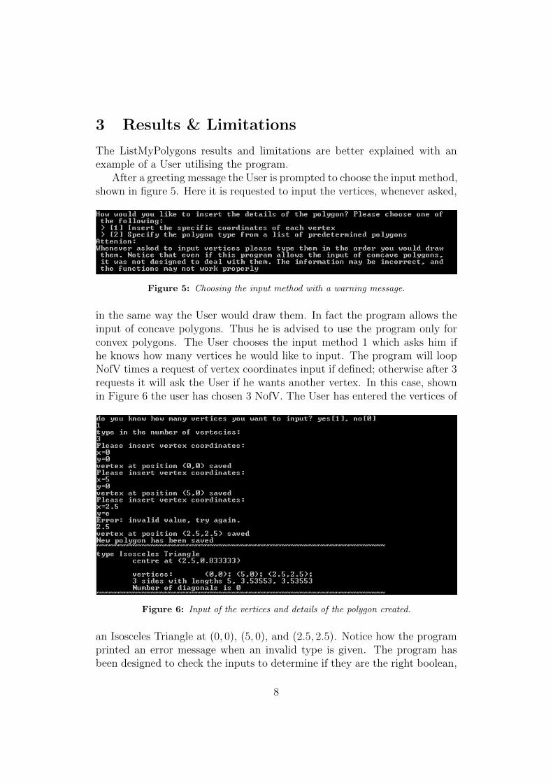
The ListMyPolygons results and limitations are better explained with anexample of a User utilising the program.
After a greeting message the User is prompted to choose the input method,shown in figure 5. Here it is requested to input the vertices, whenever asked,
Figure 5: Choosing the input method with a warning message.
in the same way the User would draw them. In fact the program allows theinput of concave polygons. Thus he is advised to use the program only forconvex polygons. The User chooses the input method 1 which asks him ifhe knows how many vertices he would like to input. The program will loopNofV times a request of vertex coordinates input if defined; otherwise after 3requests it will ask the User if he wants another vertex. In this case, shownin Figure 6 the user has chosen 3 NofV. The User has entered the vertices of
Figure 6: Input of the vertices and details of the polygon created.
an Isosceles Triangle at (0, 0), (5, 0), and (2.5, 2.5). Notice how the programprinted an error message when an invalid type is given. The program hasbeen designed to check the inputs to determine if they are the right boolean,
8
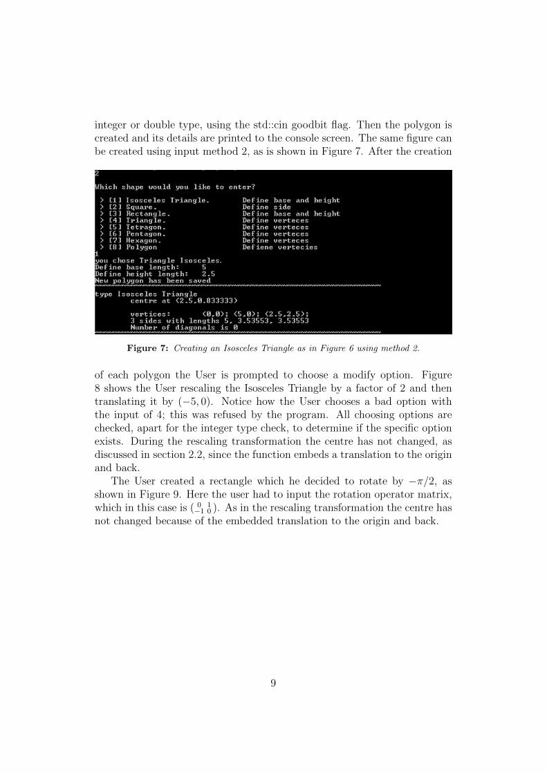
integer or double type, using the std::cin goodbit flag. Then the polygon iscreated and its details are printed to the console screen. The same figure canbe created using input method 2, as is shown in Figure 7. After the creation
Figure 7: Creating an Isosceles Triangle as in Figure 6 using method 2.
of each polygon the User is prompted to choose a modify option. Figure8 shows the User rescaling the Isosceles Triangle by a factor of 2 and thentranslating it by (−5, 0). Notice how the User chooses a bad option withthe input of 4; this was refused by the program. All choosing options arechecked, apart for the integer type check, to determine if the specific optionexists. During the rescaling transformation the centre has not changed, asdiscussed in section 2.2, since the function embeds a translation to the originand back.
The User created a rectangle which he decided to rotate by −π/2, asshown in Figure 9. Here the user had to input the rotation operator matrix,which in this case is ( 0 1
−1 0 ). As in the rescaling transformation the centre hasnot changed because of the embedded translation to the origin and back.
9
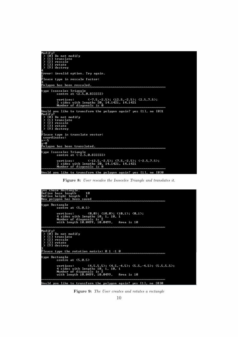
Figure 8: User rescales the Isosceles Triangle and translates it.
Figure 9: The User creates and rotates a rectangle
10
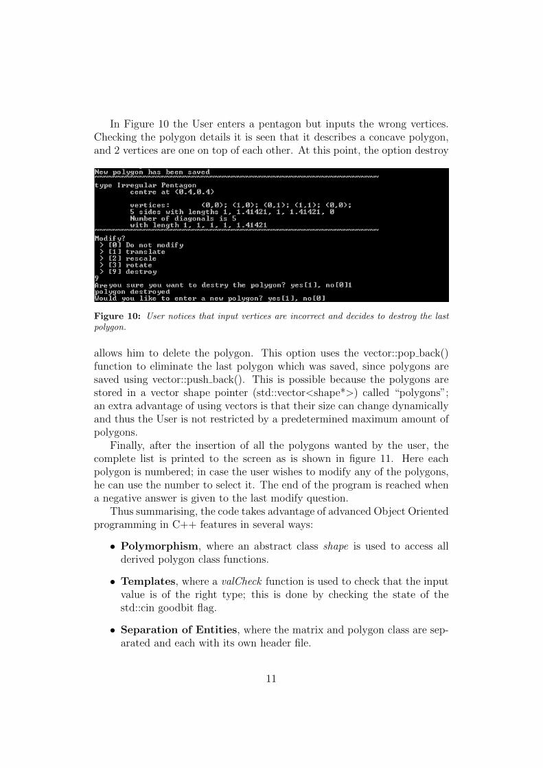
In Figure 10 the User enters a pentagon but inputs the wrong vertices.Checking the polygon details it is seen that it describes a concave polygon,and 2 vertices are one on top of each other. At this point, the option destroy
Figure 10: User notices that input vertices are incorrect and decides to destroy the lastpolygon.
allows him to delete the polygon. This option uses the vector::pop back()function to eliminate the last polygon which was saved, since polygons aresaved using vector::push back(). This is possible because the polygons arestored in a vector shape pointer (std::vector<shape*>) called “polygons”;an extra advantage of using vectors is that their size can change dynamicallyand thus the User is not restricted by a predetermined maximum amount ofpolygons.
Finally, after the insertion of all the polygons wanted by the user, thecomplete list is printed to the screen as is shown in figure 11. Here eachpolygon is numbered; in case the user wishes to modify any of the polygons,he can use the number to select it. The end of the program is reached whena negative answer is given to the last modify question.
Thus summarising, the code takes advantage of advanced Object Orientedprogramming in C++ features in several ways:
• Polymorphism, where an abstract class shape is used to access allderived polygon class functions.
• Templates, where a valCheck function is used to check that the inputvalue is of the right type; this is done by checking the state of thestd::cin goodbit flag.
• Separation of Entities, where the matrix and polygon class are sep-arated and each with its own header file.
11
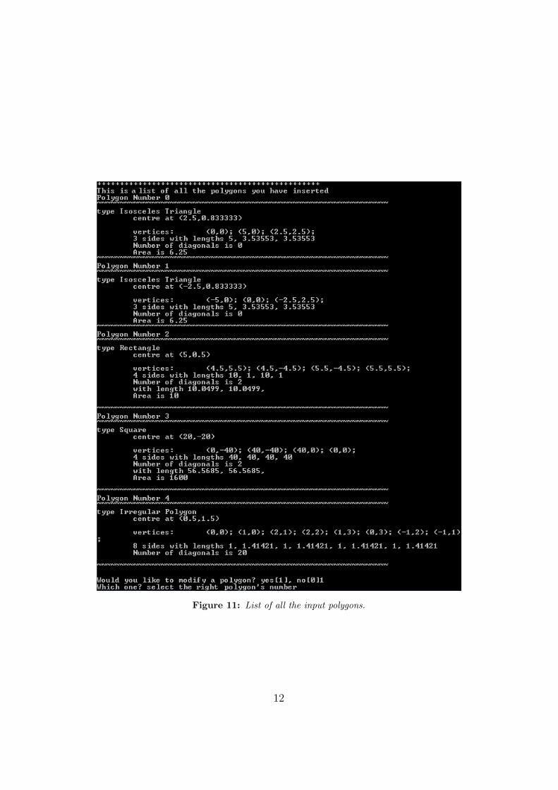
Figure 11: List of all the input polygons.
12
4 Conclusion & Discussion
The ListMyPolygons program was written to allow a User to insert severalpolygons, modify them using the Translation, Rescale and Rotation trans-formations. A polygon is essentially defined by the position of its vertices.Thus other variables like side lengths, diagonal lengths, type of polygon weredetermined from the vertices. The vertices were stored using a specifically de-signed matrix class. This allowed matrix addition and multiplication, whichwas particularly important with the matrix rotation operator in the Rota-tion transformation. Both the vertices and the polygons were stored usingthe vector STL container; this had the advantage of being able to grow, thusnot restricting the number of polygons stored or the number of vertices apolygon could have.
The program could be improved by implementing 3D polygons. Thiscould be done by a small modification of the matrix class to allow 3× 1 and3 × 3 matrices. The 3D polygon classes could inherit from the 2D classesalready established. A correction of the truncation errors could improve thereliability of regular polygons such as Equilateral Triangle. The programcould determine if a figure is concave to exclude them or use separate classesto save them in.
13