Liquitec M CM42 - fotonika.kiev.uafotonika.kiev.ua/pdf/CM42.pdf · TI381C/07/en/10.08 71080895...
36
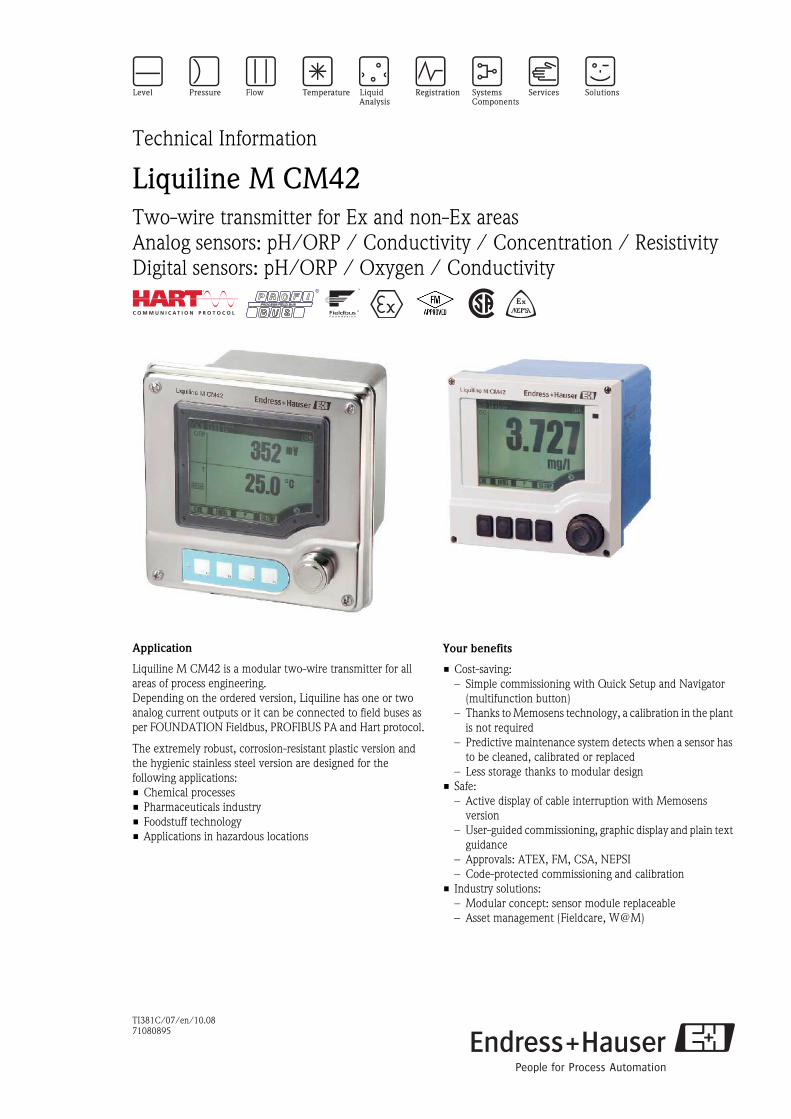
TI381C/07/en/10.08 71080895 Technical Information Liquiline M CM42 Two-wire transmitter for Ex and non-Ex areas Analog sensors: pH/ORP / Conductivity / Concentration / Resistivity Digital sensors: pH/ORP / Oxygen / Conductivity Application Liquiline M CM42 is a modular two-wire transmitter for all areas of process engineering. Depending on the ordered version, Liquiline has one or two analog current outputs or it can be connected to field buses as per FOUNDATION Fieldbus, PROFIBUS PA and Hart protocol. The extremely robust, corrosion-resistant plastic version and the hygienic stainless steel version are designed for the following applications: • Chemical processes • Pharmaceuticals industry • Foodstuff technology • Applications in hazardous locations Your benefits • Cost-saving: – Simple commissioning with Quick Setup and Navigator (multifunction button) – Thanks to Memosens technology, a calibration in the plant is not required – Predictive maintenance system detects when a sensor has to be cleaned, calibrated or replaced – Less storage thanks to modular design • Safe: – Active display of cable interruption with Memosens version – User-guided commissioning, graphic display and plain text guidance – Approvals: ATEX, FM, CSA, NEPSI – Code-protected commissioning and calibration • Industry solutions: – Modular concept: sensor module replaceable – Asset management (Fieldcare, W@M)
Transcript of Liquitec M CM42 - fotonika.kiev.uafotonika.kiev.ua/pdf/CM42.pdf · TI381C/07/en/10.08 71080895...
TI381C/07/en/10.08
71080895
Technical Information
Liquiline M CM42Two-wire transmitter for Ex and non-Ex areas
Analog sensors: pH/ORP / Conductivity / Concentration / Resistivity
Digital sensors: pH/ORP / Oxygen / Conductivity
Application
Liquiline M CM42 is a modular two-wire transmitter for all
areas of process engineering.
Depending on the ordered version, Liquiline has one or two
analog current outputs or it can be connected to field buses as
per FOUNDATION Fieldbus, PROFIBUS PA and Hart protocol.
The extremely robust, corrosion-resistant plastic version and
the hygienic stainless steel version are designed for the
following applications:
• Chemical processes
• Pharmaceuticals industry
• Foodstuff technology
• Applications in hazardous locations
Your benefits
• Cost-saving:
– Simple commissioning with Quick Setup and Navigator
(multifunction button)
– Thanks to Memosens technology, a calibration in the plant
is not required
– Predictive maintenance system detects when a sensor has
to be cleaned, calibrated or replaced
– Less storage thanks to modular design
• Safe:
– Active display of cable interruption with Memosens
version
– User-guided commissioning, graphic display and plain text
guidance
– Approvals: ATEX, FM, CSA, NEPSI
– Code-protected commissioning and calibration
• Industry solutions:
– Modular concept: sensor module replaceable
– Asset management (Fieldcare, W@M)
Liquiline M CM42
2 Endress+Hauser
Table of contents
General features . . . . . . . . . . . . . . . . . . . . . . . . . . . . . 3
Modular design . . . . . . . . . . . . . . . . . . . . . . . . . . . . . . . . . . . . . . 3
Quick setup . . . . . . . . . . . . . . . . . . . . . . . . . . . . . . . . . . . . . . . . . 3
Navigator and plain text . . . . . . . . . . . . . . . . . . . . . . . . . . . . . . . . 3
Sensor monitor . . . . . . . . . . . . . . . . . . . . . . . . . . . . . . . . . . . . . . . 3
Process check system (PCS) . . . . . . . . . . . . . . . . . . . . . . . . . . . . . 3
Memosens . . . . . . . . . . . . . . . . . . . . . . . . . . . . . . . . . . . . . . . . . . 4
Software packages . . . . . . . . . . . . . . . . . . . . . . . . . . . . . . . . . . . . 4
Safety . . . . . . . . . . . . . . . . . . . . . . . . . . . . . . . . . . . . . . . . . . . . . . 5
Special features . . . . . . . . . . . . . . . . . . . . . . . . . . . . . . 5
pH / ORP . . . . . . . . . . . . . . . . . . . . . . . . . . . . . . . . . . . . . . . . . . 5
Conductivity . . . . . . . . . . . . . . . . . . . . . . . . . . . . . . . . . . . . . . . . 6
Oxygen . . . . . . . . . . . . . . . . . . . . . . . . . . . . . . . . . . . . . . . . . . . . 6
Measuring system . . . . . . . . . . . . . . . . . . . . . . . . . . . . 7
Input . . . . . . . . . . . . . . . . . . . . . . . . . . . . . . . . . . . . . . 8
Binary input (Memosens): pH/ORP, Oxygen, Conductivity . . . . . . 8
Analog input: pH / ORP . . . . . . . . . . . . . . . . . . . . . . . . . . . . . . . . 9
Analog input: Conductivity . . . . . . . . . . . . . . . . . . . . . . . . . . . . . 10
Output . . . . . . . . . . . . . . . . . . . . . . . . . . . . . . . . . . . . 11
Output signal . . . . . . . . . . . . . . . . . . . . . . . . . . . . . . . . . . . . . . . 11
Signal on alarm . . . . . . . . . . . . . . . . . . . . . . . . . . . . . . . . . . . . . 11
Load . . . . . . . . . . . . . . . . . . . . . . . . . . . . . . . . . . . . . . . . . . . . . 11
Output signal range . . . . . . . . . . . . . . . . . . . . . . . . . . . . . . . . . . 11
Ex specification current output 4/20 mA . . . . . . . . . . . . . . . . . . 11
Ex specification PROFIBUS PA and FOUNDATION Fieldbus . . . . 12
Wiring . . . . . . . . . . . . . . . . . . . . . . . . . . . . . . . . . . . . 12
Housing grounding . . . . . . . . . . . . . . . . . . . . . . . . . . . . . . . . . . . 12
Supply and signal circuit . . . . . . . . . . . . . . . . . . . . . . . . . . . . . . . 13
Supply voltage . . . . . . . . . . . . . . . . . . . . . . . . . . . . . . . . . . . . . . 15
Sensor connection . . . . . . . . . . . . . . . . . . . . . . . . . . . . . . . . . . . 16
Sensor connection: digital sensors (Memosens)
pH/ORP/ISFET/Oxygen/ Conductivity . . . . . . . . . . . . . . . . . . . 16
Sensor connection: analog pH / ORP sensors . . . . . . . . . . . . . . . 17
Sensor connection: analog conductivity sensors . . . . . . . . . . . . . . 21
Performance characteristics. . . . . . . . . . . . . . . . . . . . 23
pH / ORP (analog and digital sensors) . . . . . . . . . . . . . . . . . . . . . 23
Conductivity (analog and digital sensors) . . . . . . . . . . . . . . . . . . . 23
Oxygen (digital sensors) . . . . . . . . . . . . . . . . . . . . . . . . . . . . . . . 24
Maximum measured error of current outputs . . . . . . . . . . . . . . . 24
Installation. . . . . . . . . . . . . . . . . . . . . . . . . . . . . . . . . 25
Mounting plate . . . . . . . . . . . . . . . . . . . . . . . . . . . . . . . . . . . . . . 25
Weather protection cover . . . . . . . . . . . . . . . . . . . . . . . . . . . . . . 25
Mounting options . . . . . . . . . . . . . . . . . . . . . . . . . . . . . . . . . . . . 26
Installation in Ex area . . . . . . . . . . . . . . . . . . . . . . . . . . . . . . . . . 27
Environment . . . . . . . . . . . . . . . . . . . . . . . . . . . . . . . 27
Ambient temperature range . . . . . . . . . . . . . . . . . . . . . . . . . . . . 27
Ambient temperature limits . . . . . . . . . . . . . . . . . . . . . . . . . . . . 27
Storage temperature . . . . . . . . . . . . . . . . . . . . . . . . . . . . . . . . . . 27
Electromagnetic compatibility . . . . . . . . . . . . . . . . . . . . . . . . . . 27
Ingress protection . . . . . . . . . . . . . . . . . . . . . . . . . . . . . . . . . . . 27
Relative humidity . . . . . . . . . . . . . . . . . . . . . . . . . . . . . . . . . . . . 27
Mechanical construction . . . . . . . . . . . . . . . . . . . . . . 28
Dimensions . . . . . . . . . . . . . . . . . . . . . . . . . . . . . . . . . . . . . . . . 28
Weight . . . . . . . . . . . . . . . . . . . . . . . . . . . . . . . . . . . . . . . . . . . 28
Material . . . . . . . . . . . . . . . . . . . . . . . . . . . . . . . . . . . . . . . . . . . 29
Human interface . . . . . . . . . . . . . . . . . . . . . . . . . . . . 29
Operating elements . . . . . . . . . . . . . . . . . . . . . . . . . . . . . . . . . . 29
Ordering information. . . . . . . . . . . . . . . . . . . . . . . . . 30
Product structure . . . . . . . . . . . . . . . . . . . . . . . . . . . . . . . . . . . . 30
Scope of delivery . . . . . . . . . . . . . . . . . . . . . . . . . . . . . . . . . . . . 31
Certificates and approvals . . . . . . . . . . . . . . . . . . . . . 31
4 approval . . . . . . . . . . . . . . . . . . . . . . . . . . . . . . . . . . . . . . . . 31
Ex approval . . . . . . . . . . . . . . . . . . . . . . . . . . . . . . . . . . . . . . . . 31
Accessories . . . . . . . . . . . . . . . . . . . . . . . . . . . . . . . . 31
Mounting kits . . . . . . . . . . . . . . . . . . . . . . . . . . . . . . . . . . . . . . 31
Weather protection cover . . . . . . . . . . . . . . . . . . . . . . . . . . . . . . 32
Active barrier . . . . . . . . . . . . . . . . . . . . . . . . . . . . . . . . . . . . . . . 32
Fieldbus accessories . . . . . . . . . . . . . . . . . . . . . . . . . . . . . . . . . . 32
Measuring cables . . . . . . . . . . . . . . . . . . . . . . . . . . . . . . . . . . . . 33
Sensors . . . . . . . . . . . . . . . . . . . . . . . . . . . . . . . . . . . . . . . . . . . 33
Software update and upgrade . . . . . . . . . . . . . . . . . . . . . . . . . . . 34

Liquiline M CM42
Endress+Hauser 3
General features
Modular design
Quick setup To the first measuring value within 1 minute
After setting up the few parameters in the Quick Setup menu, the measuring point is ready to measure. The
first measured value is reliably displayed.
Navigator and plain text The unique operating concept sets new standards:
• Fewer user errors thanks to very easy operation
• Quick configuration with the Navigator.
• Intuitive configuration and diagnosis due to plain text display
Sensor monitor You can find the sensor monitor in the DIAG menu. Important sensor data, incl. warning and alarm limits, are
displayed either graphically or numerically.
Process check system (PCS) This function checks the measuring signal for stagnation. If the measuring signal does not change for some time
(several measured values), an alarm is triggered. Soiling, blockage or similar could be the cause of such
behavior.
a0010477
Inside Liquiline (version with sensor module, without wiring)a0010476
CPU and sensor module
a0001984
Navigatora0010403
Plain text display
a0001771-en
Sensor monitor (example)
Liquiline M CM42
4 Endress+Hauser
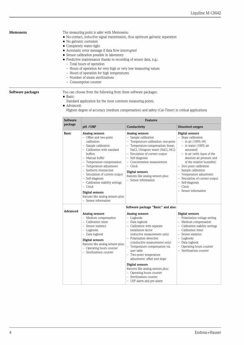
Memosens The measuring point is safer with Memosens:
• No-contact, inductive signal transmission, thus optimum galvanic separation
• No galvanic corrosion
• Completely water-tight
• Automatic error message if data flow interrupted
• Sensor calibration possible in laboratory
• Predictive maintenance thanks to recording of sensor data, e.g.:
– Total hours of operation
– Hours of operation for very high or very low measuring values
– Hours of operation for high temperatures
– Number of steam sterilizations
– Consumption counter
Software packages You can choose from the following from these software packages:
• Basic:
Standard application for the most common measuring points
• Advanced:
Highest degree of accuracy (medium compensation) and safety (Cal-Timer) in critical applications
Software
package
Features
pH /ORP Conductivity Dissolved oxygen
Basic Analog sensors
– Offset and two-point
calibration
– Sample calibration
– Calibration with standard
buffers
– Manual buffer
– Temperature compensation
– Temperature adjustment
– Isotherm intersection
– Simulation of current output
– Self-diagnosis
– Calibration stability settings
– Clock
Digital sensors
features like analog sensors plus:
– Sensor information
Analog sensors
– Sample calibration
– Temperature calibration: one-point
– Temperature compensation: linear,
NaCl, Ultrapure water (NaCl, HCl)
– Simulation of current output
– Self-diagnosis
– Concentration measurement
– Clock
Digital sensors
features like analog sensors plus:
– Sensor information
Digital sensors
– Slope calibration
– in air (100% rH)
– in water (100% air
saturated)
– in air (with input of the
absolute air pressure und
of the relative humidity)
– Zero point calibration
– Sample calibration
– Temperature adjustment
– Simulation of current output
– Self-diagnosis
– Clock
– Sensor information
Advanced
Software package "Basic" and also:
Analog sensors
– Medium compensation
– Calibration timer
– Sensor statistics
– Logbooks
– Data logbook
Digital sensors
features like analog sensors plus:
– Operating hours counter
– Sterilizations counter
Analog sensors
– Logbooks
– Data logbook
– Calibration with separate
installation factor
(inductive measurement only)
– Polarization detection
(conductive measurement only)
– Temperature compensation via
user table
– Two-point temperature
adjustment: offset and slope
Digital sensors
features like analog sensors plus:
– Operating hours counter
– Sterilizations counter
– USP alarm and pre-alarm
Digital sensors
– Polarization voltage setting
– Medium compensation
– Calibration stability settings
– Calibration timer
– Sensor statistics
– Logbooks
– Data logbook
– Operating hours counter
– Sterilizations counter

Liquiline M CM42
Endress+Hauser 5
Safety Code protection
The device offers two different user administration modes:
• Standard
– There are 3 fixed user roles (Operator, Maintenance, Expert).
– The expert can only change the maintenance password (factory setting: 0000). To do so, the expert must
log onto the device with a fixed password (4685) that cannot be changed.
– No other users can be created.
• Advanced
– You can create and manage a maximum of 15 user accounts. You need to be logged on as the expert to
do so.
– You can assign each user one of four user roles (View, Operator, Maintenance, Expert).
– Several "Experts" are possible.
– One user ("Administrator") is already created at the factory (password: 4685).
PCS: Live check
The live check issues an alarm when the sensor signal does not change over a defined period of time. This may
be caused by blocking, passivation, separation from the process, etc.
Reordering validated software
You can order new devices with older, validated software so you do not have to constantly validate new
software versions of new devices. This is possible as long as allowed by the hardware version.
Special features
pH / ORP Suitable sensors
Connection of all types of pH and ORP sensors:
• Analog and digital glass electrodes
• Analog and digital ISFET sensors
• Analog and digital ORP sensors
• Pfaudler electrodes
• Analog single electrodes (glass or antimony)
Sensor Condition Check (SCC)
This function monitors the state of the electrodes or the degree of electrode ageing. The "Electrode OK", "Low
wear" or "Replace electrode" messages inform you on the state of the electrode. The electrode state is updated
after each calibration. When the "Replace electrode" message appears, an additional error message is triggered.
Sensor Check System (SCS)
The sensor check system alerts to deviations of the pH glass impedance or reference impedance (analog sensors
only) from the normal range, thus indicating possible failure due to pH electrode blocking or damage.
In addition, the SCS detects glass breakage of glass electrodes and leakages of ISFET sensors.

Liquiline M CM42
6 Endress+Hauser
Conductivity Suitable sensors
Connection of all types of conductivity sensors:
• Analog and digital conductive sensors:
– Two-electrode sensors
– Four-electrode sensors
• Analog and digital inductive sensors
Polarization monitoring
Polarization effects in the boundary layer between the sensor and the solution to be measured limit the
measuring range of conductive conductivity sensors.
The transmitter can detect and indicate polarization effects using an innovative, intelligent signal evaluation
process.
United States Pharmacopeia (USP) and European Pharmacopoeia (EP)
The requirements on ultrapure water in the pharmaceutical industry are specified by the American USP and
the European EP.
The transmitter meets the USP/EP requirements on conductivity measuring systems:
• Precise temperature measurement at point of conductivity measurement
• Simultaneous display of uncompensated conductivity values and temperature possible
• Display resolution 0.01 μS/cm
• Exact adjustment of the transmitter in the factory with traceable precision resistances (optional)
• Exact adjustment of the sensors in the factory in accordance with ASTM D 1125-9 resp. ASTM D 5391-99
(optional)
• Temperature-dependent measured value monitoring acc. to USP and EP.
The "Advanced" software package provides the limit value functions for pharmaceutical waters acc. to USP and
EP:
• Water for Injection (WFI) acc. to USP <645> and EP
• Highly purified water (HPW) acc. to EP
• Purified water (PW) acc. to EP
The uncompensated conductivity value and the temperature are measured with the USP and EP limit value
functions. The measured values are compared with the tables described in the standards. If a limit value is
exceeded, an alarm is displayed. Additionally, a pre-alarm can be defined to indicate undesired operation states
before they occur.
Oxygen Suitable sensors
Amperometric sensors:
• with Memosens technology
• 12 and 40 mm design
Aplication-optimized calibration models
The transmitter offers separate functions for zero-point calibration and slope calibration. This allows for
optimum adaption to the process.
The calibration models range from simple slope calibration in vapour-saturated air to slope calibration with
indication of absolute air pressure and relative humidity at measuring place.
The latter model allows you to calibrate during operation as well as during sterilization or cleaning.
The transmitter has individual calibrations and sterilizations counters for sensor and membrane cap. The
counter for the membrane cap can be reset after each cap replacement.

Liquiline M CM42
Endress+Hauser 7
Measuring system
Note!
You can select from a wide variety of assemblies and sensors to set up your measuring point. You can find the
corresponding information in the chapter "Accessories" resp. in the referenced documentations.
a0002012
Measuring system: Examples
pH / ORP (analog sensor)
• CM42-P/R...
• Measuring cable CPK9
• Assembly Cleanfit CPA471
• Sensor Orbisint CPS11
Conductivity, inductive
measurement (analog)
• CM42-I...
• Assembly Dipfit CLA111
• Sensor Indumax CLS50
Conductivity, conductive
measurement (analog)
• CM42-C...
• Measuring cable CPK9
• Sensor Condumax CLS16
Memosens (digital sensor)
• CM42-K/M/N/O...
• Measuring cable CYK10
• (Assembly Unifit CPA442)
• Sensor CPS11D (pH: glass)/
CPS471D (pH: ISFET)/
COS21D/51D (oxygen) /
CLS15D/16D/21D
(conductivity, cond. meas.)

Liquiline M CM42
8 Endress+Hauser
Input
Binary input (Memosens):
pH/ORP, Oxygen,
Conductivity
Measured variable
• pH value
• Oxidation-reduction potential
• Oxygen
• Conductivity (conductive sensors)
• Resistivity
• Temperature
Measuring range
Cable specification
Ex specification
pH value –2 to 16 (glass electrodes)
0 to 14 (ISFET sensors)
ORP –1500 to +1500 mV
Dissolved oxygen 0.0 to 100.0 mg/l
0 to 1000 %SAT
0 to 2000 hPa
Conductivity, conductively measured 0.1 μS.k1)) to 20 mS.k
1) k = cell constant in cm-1
Example: 2-electrode sensor, k=0.01 cm–1, resulting measuring range: 0.001 to 200 μS/cm
Resistivity, conductively measured 10 MΩ/k to 50 Ω/k
Concentration NaOH: 0 to 15% (0 to 100 °C / 32 to 212 °F)
HNO3: 0 to 25% (0 to 80 °C / 32 to 180 °F)
H2SO4: 0 to 30% (0 to 100 °C / 32 to 212°F)
H3PO4: 0 to 15% (0 to 80 °C / 32 to 180 °F)
HCl: 0 to 20% (0 to 65 °C / 32 to 150 °F)
4 user tables
Temperature –25 to + 150 °C (–10 to 300 °F)
With Memosens 100 m (330 ft) max. cable length
Intrinsically safe sensor circuit with type of protection: Ex ia IIC1)
Power limited sensor circuit with type of protection: Ex nL IIC2)
1) CM42-*G*********, CM42-*X*********, CM42-*Z*********
2) CM42-*V*********
Max. output voltage Uo
Max. output current Io
Max. output Po
5.04 V
80 mA
112 mW
For connection to the special measuring cable CYK10
Liquiline M CM42
Endress+Hauser 9
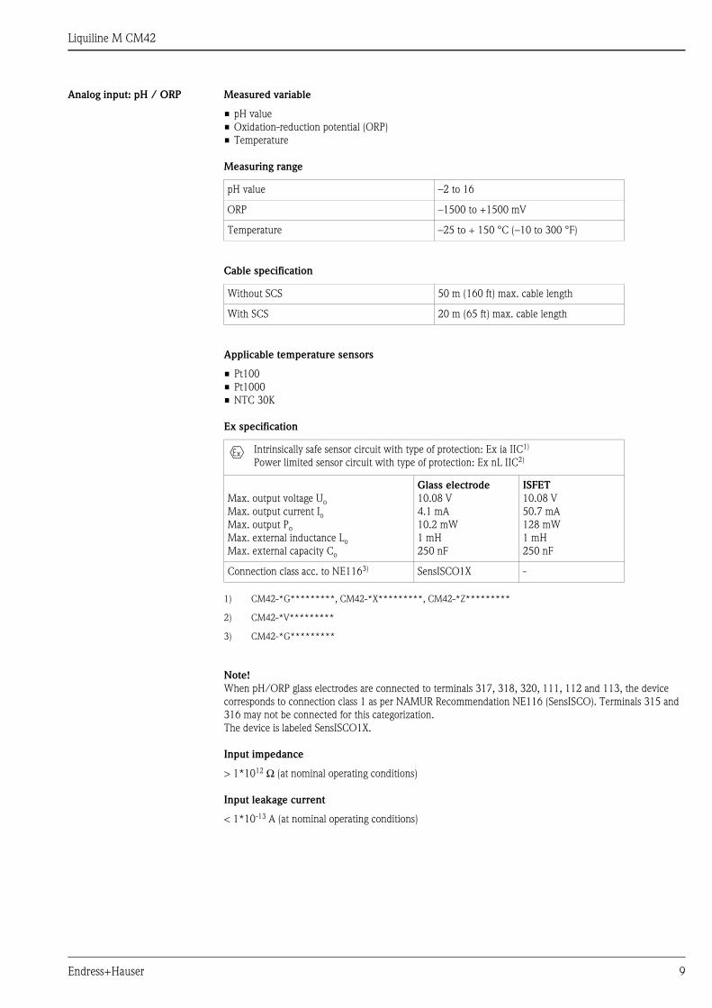
Analog input: pH / ORP Measured variable
• pH value
• Oxidation-reduction potential (ORP)
• Temperature
Measuring range
Cable specification
Applicable temperature sensors
• Pt100
• Pt1000
• NTC 30K
Ex specification
Note!
When pH/ORP glass electrodes are connected to terminals 317, 318, 320, 111, 112 and 113, the device
corresponds to connection class 1 as per NAMUR Recommendation NE116 (SensISCO). Terminals 315 and
316 may not be connected for this categorization.
The device is labeled SensISCO1X.
Input impedance
> 1*1012 Ω (at nominal operating conditions)
Input leakage current
< 1*10-13 A (at nominal operating conditions)
pH value –2 to 16
ORP –1500 to +1500 mV
Temperature –25 to + 150 °C (–10 to 300 °F)
Without SCS 50 m (160 ft) max. cable length
With SCS 20 m (65 ft) max. cable length
Intrinsically safe sensor circuit with type of protection: Ex ia IIC1)
Power limited sensor circuit with type of protection: Ex nL IIC2)
1) CM42-*G*********, CM42-*X*********, CM42-*Z*********
2) CM42-*V*********
Max. output voltage Uo
Max. output current IoMax. output Po
Max. external inductance Lo
Max. external capacity Co
Glass electrode
10.08 V
4.1 mA
10.2 mW
1 mH
250 nF
ISFET
10.08 V
50.7 mA
128 mW
1 mH
250 nF
Connection class acc. to NE1163)
3) CM42-*G*********
SensISCO1X -

Liquiline M CM42
10 Endress+Hauser
Analog input: Conductivity Measured variable
• Conductivity
• Resistivity (conductive measurement only)
• Concentration
Measuring range
Cable specification
Temperature sensor
• Pt100
• Pt1000
Ex specification, conductive sensors
Conductivity, conductively measured
Two-electrode sensor
Four-electrode sensor
0.1 μS.k1)) to 20 mS.k
0.1 μS.k to 1.5 S.k
1) k = cell constant in cm-1
Example: 2-electrode sensor, k=0.01 cm–1, resulting measuring range: 0.001 to 200 μS/cm
Conductivity, inductively measured 1.7 μS.k2)) to 1 S.k
2) k=cell constant in cm–1 Example: sensor, k=2 cm–1, resulting measuring range: 3.4 μS/cm to 2 S/cm
Resistivity, conductively measured 10 MΩ/k to 50 Ω/k
Concentration NaOH: 0 to 15% (0 to 100 °C / 32 to 212 °F)
HNO3: 0 to 25% (0 to 80 °C / 32 to 180 °F)
H2SO4: 0 to 30% (0 to 100 °C / 32 to 212°F)
H3PO4: 0 to 15% (0 to 80 °C / 32 to 180 °F)
HCl: 0 to 20% (0 to 65 °C / 32 to 150 °F)
4 user tables
Conductivity/resistivity, conductively measured1))
Two-electrode sensor
10 μS.k to 20 mS.k / 0.1 MΩ/k to 50 Ω/k
5 μS.k to 20 mS.k / 0.2 MΩ/k to 50 Ω/k
0.1 μS.k to 20 mS.k / 20 MΩ/k to 50 Ω/k
1) with CYK71 or CPK9 cables or sensor fixed cable
100 m (330 ft) max. cable length
50 m (160 ft) max. cable length
15 m (50 ft) max. cable length
Conductivity, conductively measured
Four-electrode sensor
10 μS.k to 1.5 S.k
0.1 μS.k to 20 mS.k
100 m (330 ft) max. cable length
15 m (50 ft) max. cable length
Conductivity, inductively measured2))
2) with CLK5 cable or sensor fixed cable
55 m (180 ft) max. cable length
Intrinsically safe sensor circuit with type of protection: Ex ia IIC1)
Power limited sensor circuit with type of protection: Ex nL IIC2)
1) CM42-*G*********, CM42-*X*********, CM42-*Z*********
2) CM42-*V*********
Max. output voltage Uo
Max. output current Io
Max. output Po
Max. external inductance Lo
Max. external capacity Co
10.08 V
23 mA
57 mW
300 μH
50 nF

Liquiline M CM42
Endress+Hauser 11
Ex specification, inductive sensors
Output
Output signal 1x 4 to 20 mA, potentially isolated against sensor circuit1)
2x 4 to 20 mA, potentially isolated against sensor circuit2)
PROFIBUS PA3)
FOUNDATION Fieldbus4)
Signal on alarm 3.6 to 22.0 mA
digital via field bus5)
Load Max. load with an supply voltage of 24 V: 500 ΩMax. load with an supply voltage of 30 V: 750 Ω
Output signal range
Ex specification
current output 4/20 mA
Intrinsically safe sensor circuit with type of protection: Ex ia IIC1)
Power limited sensor circuit with type of protection: Ex nL IIC2)
1) CM42-*G*********, CM42-*X*********, CM42-*Z*********
2) CM42-*V*********
Max. output voltage Uo
Max. output current IoMax. external Po
10.08 V
64 mA
128 mW
For connection of the inductive sensors CLS50, CLS54
1) current output 1, potential isolation with Memosens: in sensor plug
2) current output 1 and current output 2 (optional)
3) for version with PROFIBUS PA
4) for version with FOUNDATION Fieldbus
5) with Profibus PA or FOUNDATION Fieldbus only
pH adjustable, ΔpH > 0.5
ORP adjustable, ΔU > 5 mV
Dissolved oxygen adjustable
Conductivity, conductive measured adjustable
Conductivity, inductive measured adjustable
Temperature adjustable, Δϑ > 2 °C (2 °F)
Intrinsically safe supply and signal circuits, passive
Max. input voltage Ui
Max. input current Ii
Max. input Pi
Max. internal inductivity Li
Max. internal capacity Ci
30 V
100 mA
750 mW
29 μH (output 1)
24 μH (output 2)
1.2 nF (output 1)
0.2 nF (output 2)
Liquiline M CM42
12 Endress+Hauser
Ex specification PROFIBUS PA
and FOUNDATION Fieldbus
Wiring
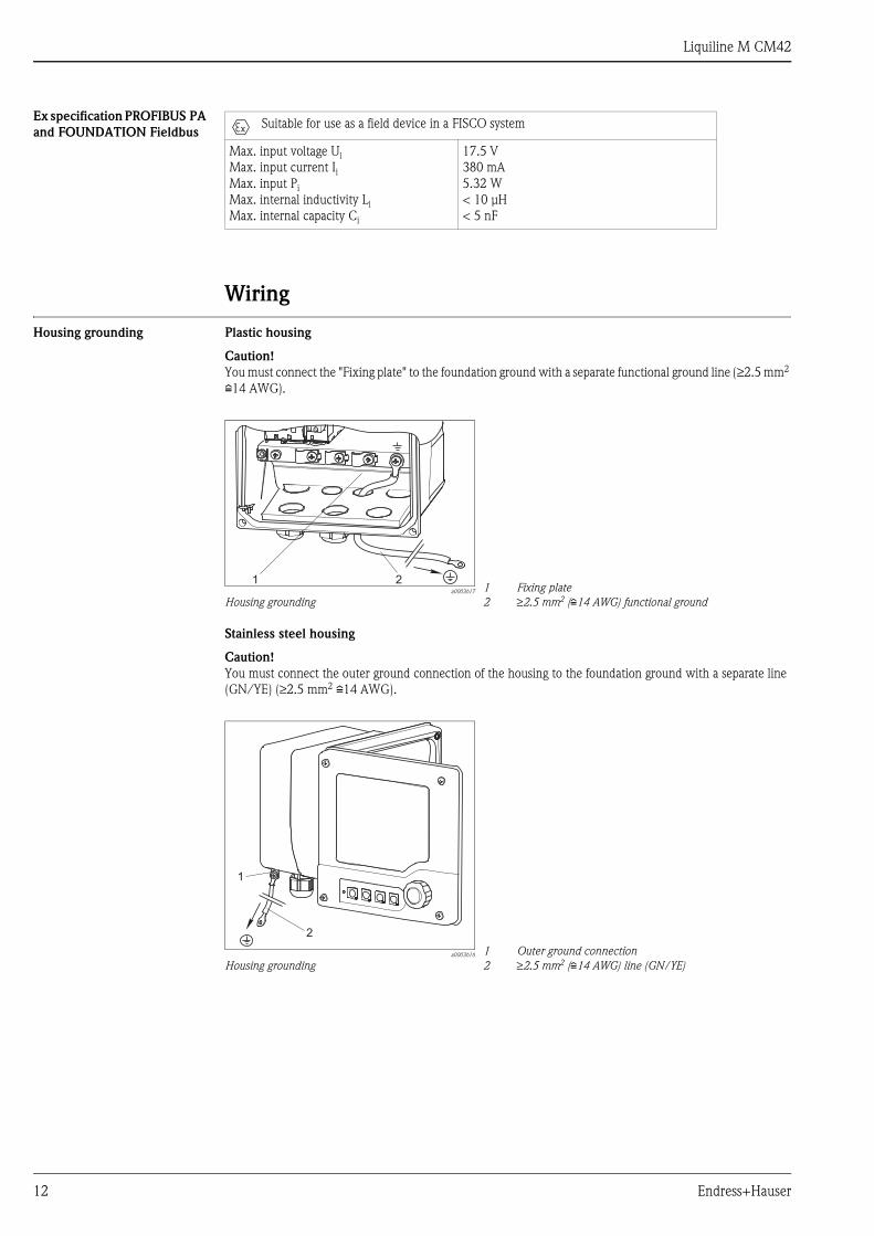
Housing grounding Plastic housing
Caution!
You must connect the "Fixing plate" to the foundation ground with a separate functional ground line (≥2.5 mm2
i14 AWG).
Stainless steel housing
Caution!
You must connect the outer ground connection of the housing to the foundation ground with a separate line
(GN/YE) (≥2.5 mm2 i14 AWG).
Suitable for use as a field device in a FISCO system
Max. input voltage Ui
Max. input current Ii
Max. input Pi
Max. internal inductivity Li
Max. internal capacity Ci
17.5 V
380 mA
5.32 W
< 10 μH
< 5 nF
a0003617
Housing grounding
1
2
Fixing plate
≥2.5 mm2 (i14 AWG) functional ground
a0003616
Housing grounding
1
2
Outer ground connection
≥2.5 mm2 (i14 AWG) line (GN/YE)
Liquiline M CM42
Endress+Hauser 13
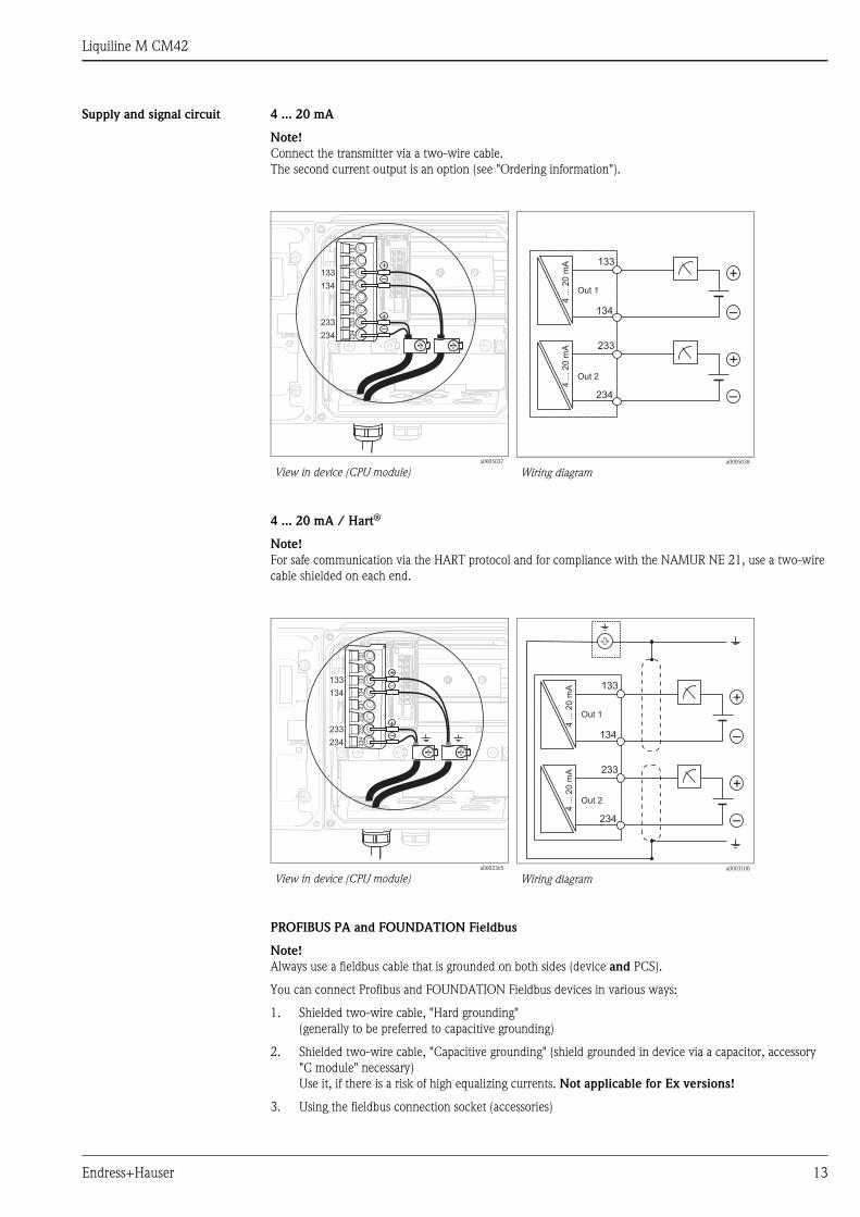
Supply and signal circuit 4 ... 20 mA
Note!
Connect the transmitter via a two-wire cable.
The second current output is an option (see "Ordering information").
4 ... 20 mA / Hart®
Note!
For safe communication via the HART protocol and for compliance with the NAMUR NE 21, use a two-wire
cable shielded on each end.
PROFIBUS PA and FOUNDATION Fieldbus
Note!
Always use a fieldbus cable that is grounded on both sides (device and PCS).
You can connect Profibus and FOUNDATION Fieldbus devices in various ways:
1. Shielded two-wire cable, "Hard grounding"
(generally to be preferred to capacitive grounding)
2. Shielded two-wire cable, "Capacitive grounding" (shield grounded in device via a capacitor, accessory
"C module" necessary)
Use it, if there is a risk of high equalizing currents. Not applicable for Ex versions!
3. Using the fieldbus connection socket (accessories)
a0005037
View in device (CPU module)a0005038
Wiring diagram
a0002365
View in device (CPU module)a0003100
Wiring diagram
+
–
133
134
4..
.20
mA
+
–
233
234
4..
.20
mA
Out 1
Out 2
Liquiline M CM42
14 Endress+Hauser
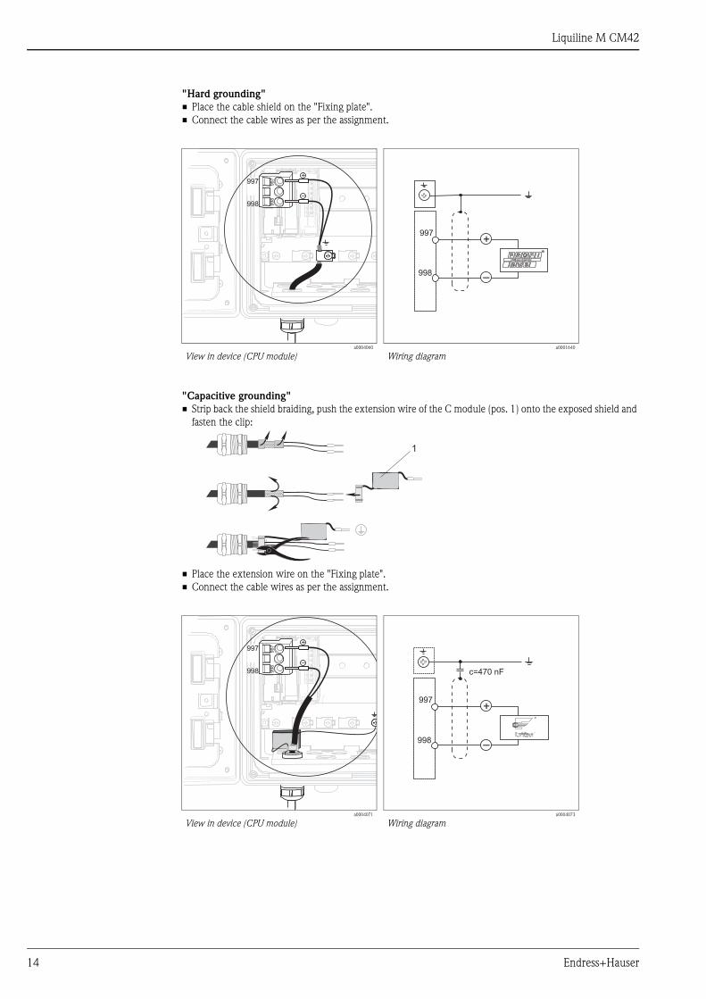
"Hard grounding"
• Place the cable shield on the "Fixing plate".
• Connect the cable wires as per the assignment.
"Capacitive grounding"
• Strip back the shield braiding, push the extension wire of the C module (pos. 1) onto the exposed shield and
fasten the clip:
• Place the extension wire on the "Fixing plate".
• Connect the cable wires as per the assignment.
a0004060
View in device (CPU module)a0001640
Wiring diagram
a0004071
View in device (CPU module)a0004073
Wiring diagram
Liquiline M CM42
Endress+Hauser 15
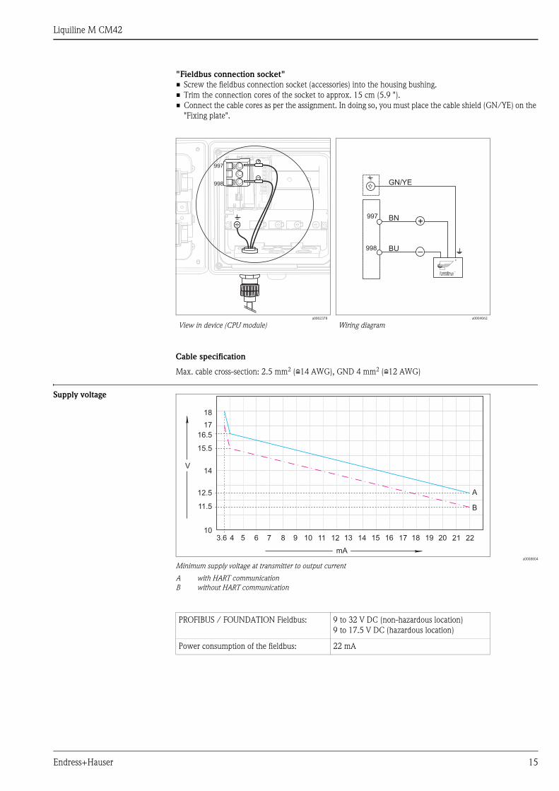
"Fieldbus connection socket"
• Screw the fieldbus connection socket (accessories) into the housing bushing.
• Trim the connection cores of the socket to approx. 15 cm (5.9 ").
• Connect the cable cores as per the assignment. In doing so, you must place the cable shield (GN/YE) on the
"Fixing plate".
Cable specification
Max. cable cross-section: 2.5 mm2 (i14 AWG), GND 4 mm2 (i12 AWG)
Supply voltage
a0008804
Minimum supply voltage at transmitter to output current
A with HART communication
B without HART communication
a0002378
View in device (CPU module)a0004062
Wiring diagram
V
mA
10
12.5
11.5
14
15.5
16.5
18
53.6 6 7 8 9 10 11 12 13 14 15 16 17 18 19 20 21 22
A
B
17
4
PROFIBUS / FOUNDATION Fieldbus: 9 to 32 V DC (non-hazardous location)
9 to 17.5 V DC (hazardous location)
Power consumption of the fieldbus: 22 mA
Liquiline M CM42
16 Endress+Hauser
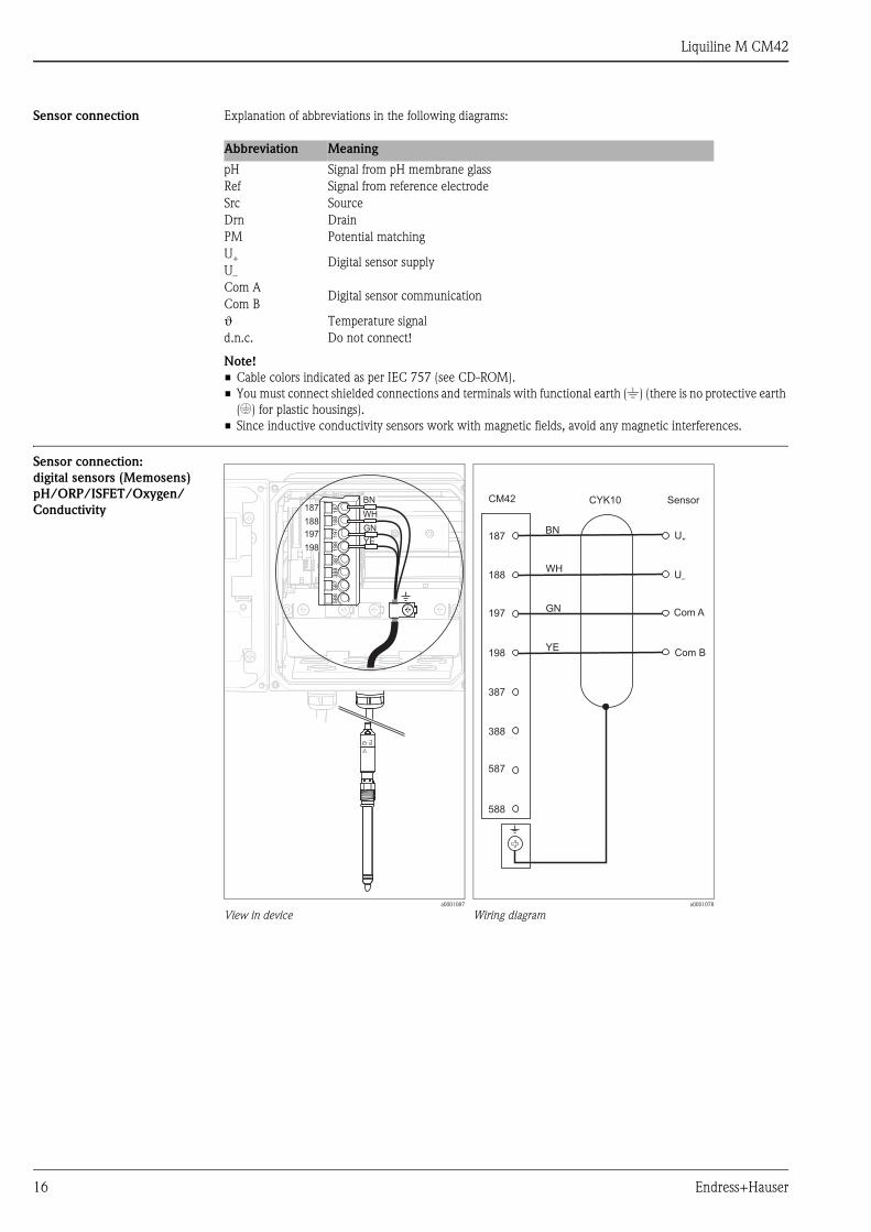
Sensor connection Explanation of abbreviations in the following diagrams:
Note!
• Cable colors indicated as per IEC 757 (see CD-ROM).
• You must connect shielded connections and terminals with functional earth ()) (there is no protective earth
(*) for plastic housings).
• Since inductive conductivity sensors work with magnetic fields, avoid any magnetic interferences.
Sensor connection:
digital sensors (Memosens)
pH/ORP/ISFET/Oxygen/
Conductivity
Abbreviation Meaning
pH Signal from pH membrane glass
Ref Signal from reference electrode
Src Source
Drn Drain
PM Potential matching
U+ Digital sensor supplyU–
Com ADigital sensor communication
Com B
ϑ Temperature signal
d.n.c. Do not connect!
a0001087
View in devicea0001078
Wiring diagram
Liquiline M CM42
Endress+Hauser 17
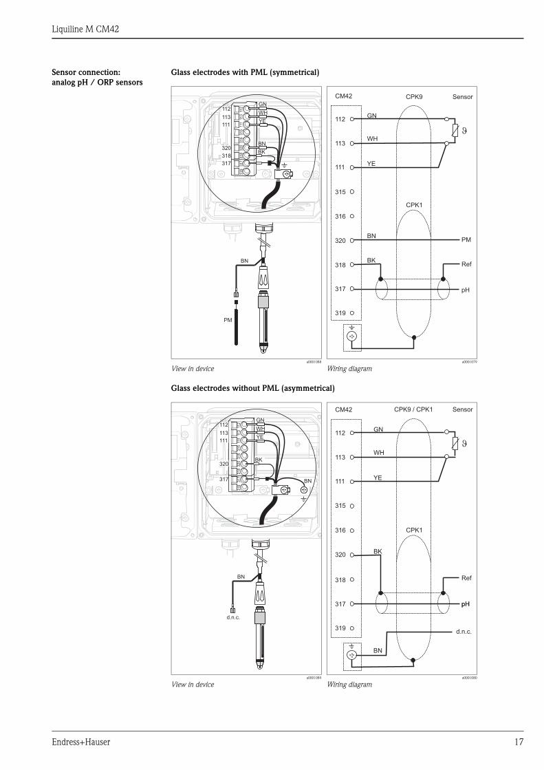
Sensor connection:
analog pH / ORP sensors
Glass electrodes with PML (symmetrical)
Glass electrodes without PML (asymmetrical)
a0001088
View in devicea0001079
Wiring diagram
a0001089
View in devicea0001080
Wiring diagram
BK
BN
GN
WH
YE
CPK9
318
320
112
113
111
317
CM42
319
316
315
J
PM
Ref
pH
Sensor
CPK1
BK
BN
GN
WH
YE
318
320
112
113
111
317
CM42
319
315
316
CPK9 / CPK1
J
d.n.c.
Ref
pH
Sensor
pH
CPK1

Liquiline M CM42
18 Endress+Hauser
ISFET sensors with PML (symmetrical)
ISFET sensors without PML (asymmetrical)
a0001090
View in devicea0001076
Wiring diagram
a0001084
View in devicea0001077
Wiring diagram
BK
BN
GN
WH
YE
CPK12
317
318
112
113
111
319
CM42
315
316
320
RD
Src
J
Ref
PM
Drn
Sensor
BK
BN
GN
WH
YE
317
318
112
113
111
319
CM42
315
316
320
RD
Src
Ref
Drn
J
d.n.c.
CPK12 Sensor

Liquiline M CM42
Endress+Hauser 19
Pfaudler electrodes
With PM (symmetrical)
Pfaudler electrode, absolute
Type 03 / Type 04
With PM (symmetrical)
Pfaudler electrode, relative
Type 18 / Type 40
a0010467
Wiring diagrama0010468
Wiring diagram
With PM (symmetrical)
pH Reiner
Without PM (asymmetrical)
Pfaudler electrode, absolute
Type 03 / Type 04
a0010469
Wiring diagrama0010470
Wiring diagram
BU
318
320
112
113
111
317
CM42
319
316
315
5
1
Pfaudler18/40
OG
VT
3
4
6
pH
PM
WH
BN2
Ref
BN
GN
BK
�
8
9Shield
Liquiline M CM42
20 Endress+Hauser
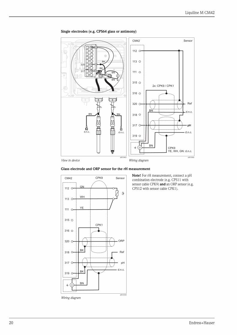
Single electrodes (e.g. CPS64 glass or antimony)
Glass electrode and ORP sensor for the rH measurement
a0010465
View in devicea0010466
Wiring diagram
a0010558
Wiring diagram
Note! For rH measurement, connect a pH
combination electrode (e.g. CPS11 with
sensor cable CPK9) and an ORP sensor (e.g.
CPS12 with sensor cable CPK1).
BN
318
320
112
113
111
317
CM42
319
315
316
CPK1
d.n.c.
pH
Sensor
ORP
BK
CPK9
Ref
GN
WH
YE
�
BK
Liquiline M CM42
Endress+Hauser 21
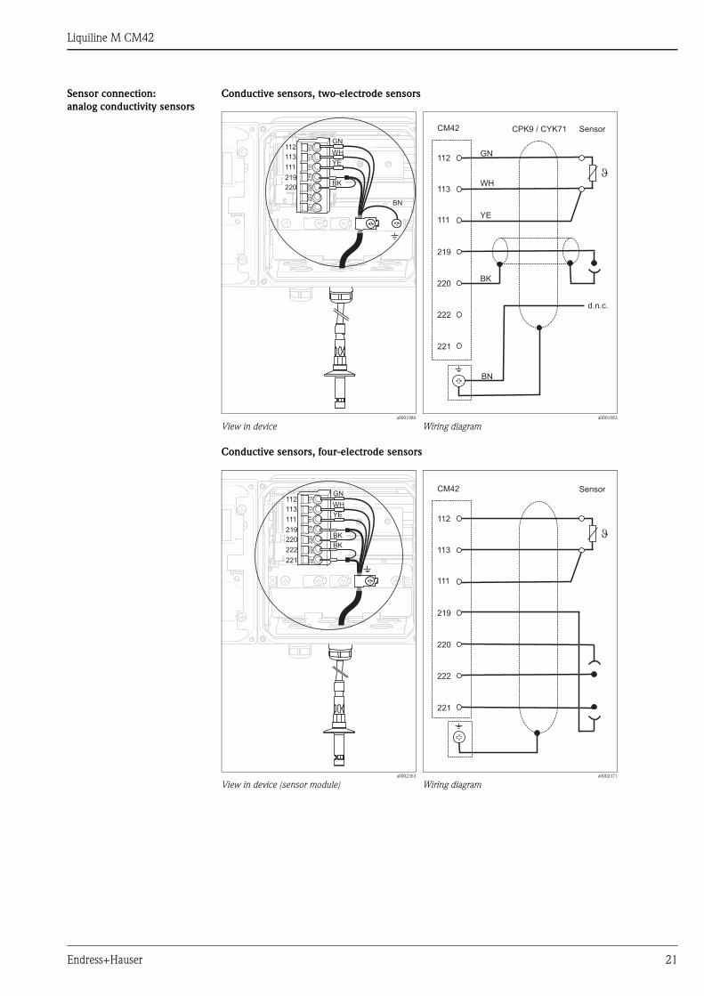
Sensor connection:
analog conductivity sensors
Conductive sensors, two-electrode sensors
Conductive sensors, four-electrode sensors
a0001086
View in devicea0001083
Wiring diagram
a0002363
View in device (sensor module)a0002371
Wiring diagram
BK
BN
GN
WH
YE
CPK9 / CYK71
221
222
112
113
111
CM42
220
219
J
Sensor
d.n.c.
221
222
112
113
111
CM42
220
219
J
Sensor

Liquiline M CM42
22 Endress+Hauser
Inductive sensors
a0001085
View in devicea0001082
Wiring diagram
Liquiline M CM42
Endress+Hauser 23
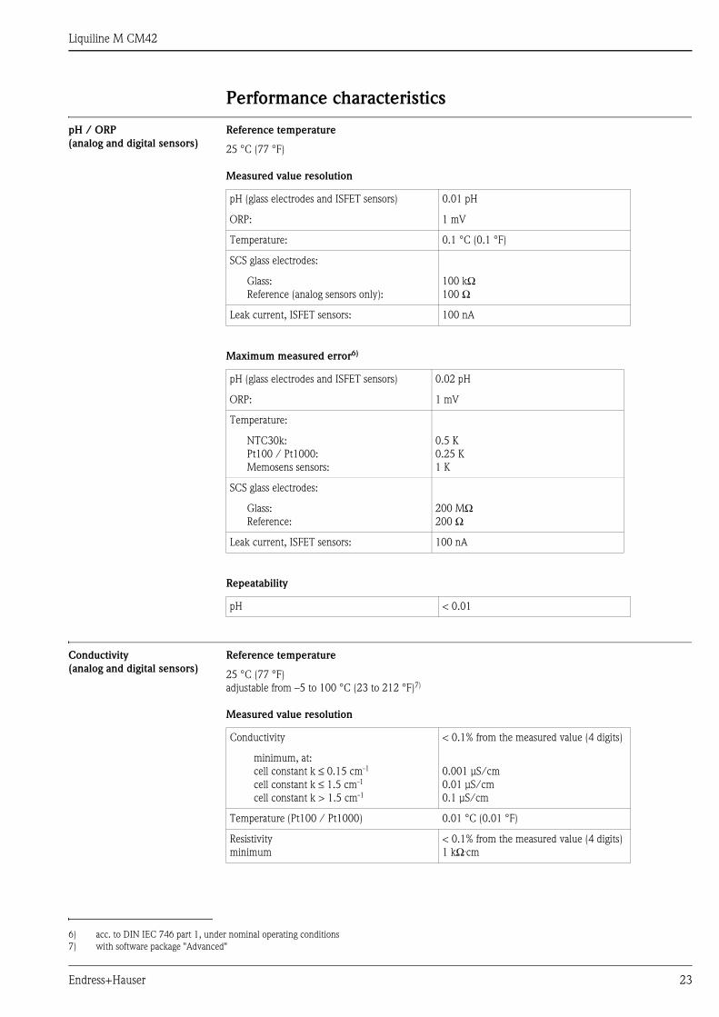
Performance characteristics
pH / ORP
(analog and digital sensors)
Reference temperature
25 °C (77 °F)
Measured value resolution
Maximum measured error6)
Repeatability
Conductivity
(analog and digital sensors)
Reference temperature
25 °C (77 °F)
adjustable from –5 to 100 °C (23 to 212 °F)7)
Measured value resolution
pH (glass electrodes and ISFET sensors) 0.01 pH
ORP: 1 mV
Temperature: 0.1 °C (0.1 °F)
SCS glass electrodes:
Glass:
Reference (analog sensors only):
100 kΩ100 Ω
Leak current, ISFET sensors: 100 nA
6) acc. to DIN IEC 746 part 1, under nominal operating conditions
pH (glass electrodes and ISFET sensors) 0.02 pH
ORP: 1 mV
Temperature:
NTC30k:
Pt100 / Pt1000:
Memosens sensors:
0.5 K
0.25 K
1 K
SCS glass electrodes:
Glass:
Reference:
200 MΩ200 Ω
Leak current, ISFET sensors: 100 nA
pH < 0.01
7) with software package "Advanced"
Conductivity < 0.1% from the measured value (4 digits)
minimum, at:
cell constant k ≤ 0.15 cm-1
cell constant k ≤ 1.5 cm-1
cell constant k > 1.5 cm-1
0.001 μS/cm
0.01 μS/cm
0.1 μS/cm
Temperature (Pt100 / Pt1000) 0.01 °C (0.01 °F)
Resistivity
minimum
< 0.1% from the measured value (4 digits)
1 kΩ.cm

Liquiline M CM42
24 Endress+Hauser
Maximum measured error8)
Temperature compensation
Temperature adjustment
Oxygen (digital sensors) Measured value resolution
Maximum measured error9)
Maximum measured error
of current outputs
8) acc. to DIN IEC 746 part 1, under nominal operating conditions
Conductivity, conductive measured
Two-electrode sensors 0.5 % from measured value ±0.01 μS.k
Four-electrode sensors 0.5 % from measured value ±0.01 μS.k 1))
1.0 % from measured value ±0.01 μS.k 2))
2.0 % from measured value ±0.01 μS.k 3))
1) from 0.1 μS.k to 20 mS.k (max. cable length 15 m (50 ft))
2) from 10 μS.k to 1000 mS.k (max. cable length 100 m (330 ft))
3) from 10 μS.k to 1500 mS.k (max. cable length 100 m (330 ft))
Conductivity, inductive measured 0.5 % from measured value ±1.7 μS.k
Resistivity, conductive measured
(two-electrode sensors)
0.5 % from measured value ±0.01 μS.k 4))
4) from 10 MΩ/k to 50 Ω/k (max. cable length 15 m (50 ft))
from 200 kΩ/k to 50 Ω/k (max. cable length 50 m (160 ft))
Type of compensation
none
linear
NaCl acc. to IEC 746-3
natural waters acc. to IEC 7888
Ultra-pure water NaCl
Ultra-pure water HCl (for NH3 as well)
4 user tables 1))
1) with software package "Advanced"
Range
α = 0.00 to 20.00 % / K
0 to 100 °C (32 to 212 °F)
0 to 35 °C (32 to 95 °F)
0 to 100 °C (32 to 212 °F)
0 to 100 °C (32 to 212 °F)
Temperature offset
Temperature slope
–5 to +5 °C (23 to 41 °F)
0.9 to 1.11))
1) with software package "Advanced"
Dissolved oxygen 0.01 resp. 0.001 mg/l (append. on sensor)
Temperature 0.1 °C (0.1 °F)
9) acc. to DIN IEC 746 part 1, under nominal operating conditions
Dissolved oxygen 1% of measured value
Temperature 1 K
Current outputs, additionally 25 μA
Liquiline M CM42
Endress+Hauser 25
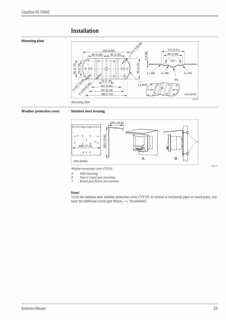
Installation
Mounting plate
Weather protection cover Stainless steel housing
a0001676
Weather protection cover CYY101
A Wall mounting
B Pipe or round post mounting
1 Round post fixture (Accessories)
Note!
To fix the stainless steel weather protection cover CYY101 to vertical or horizontal pipes or round posts, you
need the additional round post fixture, --> "Accessories".
a0010363
Mounting plate
220 (8.66)
85 (3.35)
70 (2.76)
141 (5.55)
196 (7.72)
70
(2.7
6)
85 (3.35)
95
(3.7
4)
mm (inch)
122°
2 x R8 2 x R3
R3
2 x R8
2(0
.08
)
86 (3.39)
112 (4.41)
161 (6.34)
4xØ
6(0
.24)
2x11
(0.4
3)
4xØ
7(0
.28)
80
(3.1
5)
2 x R70

Liquiline M CM42
26 Endress+Hauser
Plastic housing
Mounting options
a0001671-en
Weather protection cover
a0002166
Wall mounting
– Weather protection cover is optional
a0003092
Pipe or post mounting
1 Liquiline CM42
2, 3 Mounting plate (1x accessories)
4 Pipe or post
a0005036
Panel mounting
1
4 3
2
Wall mounting Pipe mounting Panel installation
without protection cover Mounting plate: in standard Mounting kit: 51518263 Installation kit: 51518173
with protection cover Protection cover: 51517382 Mounting kit:
Protection cover:
51518263
51517382
without protection cover Mounting plate: in standard Mounting kit: 51518286 Installation kit: 51518284
with protection cover Protection cover: CYY101-A Protection cover:
Round post
installation:
CYY101-A
50062121
Liquiline M CM42
Endress+Hauser 27
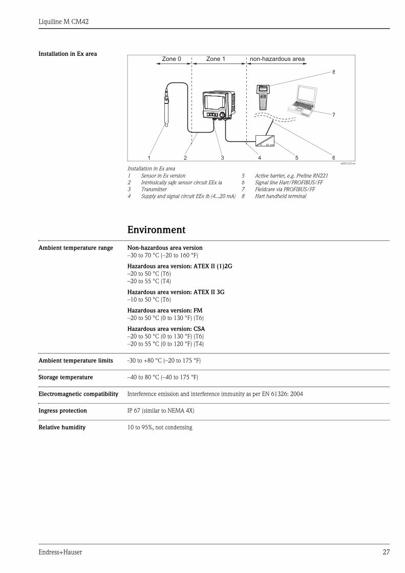
Installation in Ex area
Environment
Ambient temperature range Non-hazardous area version
–30 to 70 °C (–20 to 160 °F)
Hazardous area version: ATEX II (1)2G
–20 to 50 °C (T6)
–20 to 55 °C (T4)
Hazardous area version: ATEX II 3G
–10 to 50 °C (T6)
Hazardous area version: FM
–20 to 50 °C (0 to 130 °F) (T6)
Hazardous area version: CSA
–20 to 50 °C (0 to 130 °F) (T6)
–20 to 55 °C (0 to 120 °F) (T4)
Ambient temperature limits -30 to +80 °C (–20 to 175 °F)
Storage temperature –40 to 80 °C (–40 to 175 °F)
Electromagnetic compatibility Interference emission and interference immunity as per EN 61326: 2004
Ingress protection IP 67 (similar to NEMA 4X)
Relative humidity 10 to 95%, not condensing
a0001312-en
Installation in Ex area
1
2
3
4
Sensor in Ex version
Intrinsically safe sensor circuit EEx ia
Transmitter
Supply and signal circuit EEx ib (4...20 mA)
5
6
7
8
Active barrier, e.g. Preline RN221
Signal line Hart/PROFIBUS/FF
Fieldcare via PROFIBUS/FF
Hart handheld terminal

Liquiline M CM42
28 Endress+Hauser
Mechanical construction
Dimensions Plastic housing
Stainless steel housing
Weight Plastic housing
1.5 kg (3.3 lb)
Stainless steel housing
2.1 kg (4.6 lb)
a0001074-en
Plastic housing
a0001073-en
Dimensions
14
5/
5.7
1
13
4/
5.2
8
11
0/
4.3
3
132.5 / 5.22
136.5 / 5.37
16
0/
6.3
0
134.5 / 5.30
136.5 / 5.37
26 /1.02
174 / 6.85
17
4/
6.8
5
10
/0
.39
3/
0.1
2
220 / 8.66
95
/3
.74
mm / inch

Liquiline M CM42
Endress+Hauser 29
Material Plastic housing
Stainless steel housing
Human interface
Operating elements
Housing:
Housing seals:
Polycarbonate
Foamed silicone, EPDM
Housing:
Housing seals:
Stainless steel 1.4301 (AISI 304)
EPDM
a0010480
Overview of operation
1 Display, current display: pH measuring mode
2 Navigator
3-6 Soft keys
7 Soft key function (depends on menu)
1
23456
7
Liquiline M CM42
30 Endress+Hauser
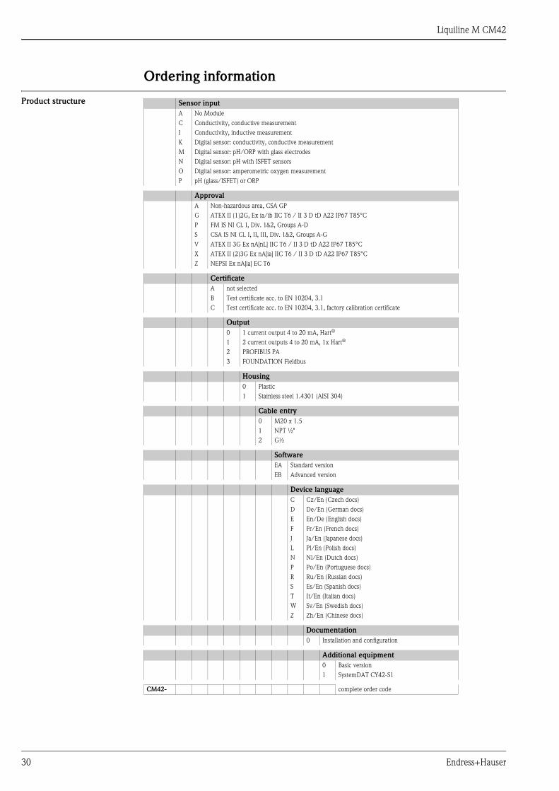
Ordering information
Product structure Sensor input
A No Module
C Conductivity, conductive measurement
I Conductivity, inductive measurement
K Digital sensor: conductivity, conductive measurement
M Digital sensor: pH/ORP with glass electrodes
N Digital sensor: pH with ISFET sensors
O Digital sensor: amperometric oxygen measurement
P pH (glass/ISFET) or ORP
Approval
A Non-hazardous area, CSA GP
G ATEX II (1)2G, Ex ia/ib IIC T6 / II 3 D tD A22 IP67 T85°C
P FM IS NI Cl. I, Div. 1&2, Groups A-D
S CSA IS NI Cl. I, II, III, Div. 1&2, Groups A-G
V ATEX II 3G Ex nA[nL] IIC T6 / II 3 D tD A22 IP67 T85°C
X ATEX II (2)3G Ex nA[ia] IIC T6 / II 3 D tD A22 IP67 T85°C
Z NEPSI Ex nA[ia] EC T6
Certificate
A not selected
B Test certificate acc. to EN 10204, 3.1
C Test certificate acc. to EN 10204, 3.1, factory calibration certificate
Output
0 1 current output 4 to 20 mA, Hart®
1 2 current outputs 4 to 20 mA, 1x Hart®
2 PROFIBUS PA
3 FOUNDATION Fieldbus
Housing
0 Plastic
1 Stainless steel 1.4301 (AISI 304)
Cable entry
0 M20 x 1.5
1 NPT ½"
2 G½
Software
EA Standard version
EB Advanced version
Device language
C Cz/En (Czech docs)
D De/En (German docs)
E En/De (English docs)
F Fr/En (French docs)
J Ja/En (Japanese docs)
L Pl/En (Polish docs)
N Nl/En (Dutch docs)
P Po/En (Portuguese docs)
R Ru/En (Russian docs)
S Es/En (Spanish docs)
T It/En (Italian docs)
W Sv/En (Swedish docs)
Z Zh/En (Chinese docs)
Documentation
0 Installation and configuration
Additional equipment
0 Basic version
1 SystemDAT CY42-S1
CM42- complete order code
Liquiline M CM42
Endress+Hauser 31
Scope of delivery The scope of delivery comprises (depending on the device version):
• A transmitter acc. to the ordered version
• A mounting plate including 4 screws
• A sticker sheet (embedded in the housing, containing nameplates and terminal assignment stickers)
• A test certificate acc. to EN 10204-3.1 (optional)
• A factory calibration certificate
• An Operating Instructions BA381C "Commissioning"
• An Operating Instructions BA382C "Operation"
• A Safety Manual acc. to SIL 2 (optional)
• A CD ROM with additional documentation
Certificates and approvals
4 approval Declaration of conformity
The product meets the requirements of the harmonized European standards. It thus complies with the legal
requirements of the EC directives.
The manufacturer confirms successful testing of the product by affixing the 4 symbol.
Ex approval Depending on the version ordered:
• ATEX II (1)2G, Ex ia/ib IIC T6 / II 3 D tD A22 IP67 T85°C
• ATEX II 3G Ex nA[nL] IIC T6 / II 3 D tD A22 IP67 T85°C
• ATEX II (2)3G Ex nA[ia] IIC T6 / II 3 D tD A22 IP67 T85°C
• NEPSI Ex nA[ia] EC T6
• CSA IS NI Cl.I, II, III, Div. 1&2, Grps. A-G
• FM IS NI Cl.I, Div. 1&2, Grps. A-D
AccessoriesNote!
In the following sections, you find the accessories available at the time of issue of this documentation.
For information on accessories that are not listed here, please contact your local service.
Mounting kits Post mounting kit for plastic housing
• 1 Mounting plate
• 2 Threaded rods M5x75 mm A2
• 2 Hexagonal nuts M5 A2, DIN 934
• 2 Spring washers, A2 DIN127, Form B5 (M5)
• 2 Washers A 5.3, DIN125 A2
• order no. 51518263
Post mounting kit for stainless steel housing
• 1 Mounting plate
• 2 Threaded rods M5x75 mm A2
• 2 Hexagonal nuts M5 A2, DIN 934
• 2 Spring washers, DIN127, Form B5 (M5)
• 2 Washers A 5.3, DIN125 A2
• order no. 51518286
Panel installation kit for plastic housing for panel cutout 138x138 mm (5.43x5.43 inch)
• 1 Panel installation seal
• 2 Tensioning screws M6x150 mm
• 4 Hexagonal nuts M6, DIN934 A2
• 4 Spring washers, A2 DIN127, Form B6
• 4 Washers A6.4, DIN125 A2
• order no. 51518173
Liquiline M CM42
32 Endress+Hauser
Panel installation kit for stainless steel housing for panel cutout 138x138 mm (5.43x5.43 inch)
• 1 Panel installation seal
• 2 Tensioning screws M6x150 mm
• 4 Hexagonal nuts M6, DIN934 A2
• 4 Spring washers, A2 DIN127, Form B6
• 4 Washers A6.4, DIN125 A2
• order no. 51518284
Weather protection cover • Weather protection cover for plastic housing
order no. 51517382
• Weather protection cover for stainless steel housing
order no. CYY101-A
Active barrier Active barrier RN221N
• With power supply for safe separation of 4 to 20 mA current circuits
• Technical Information TI073R/09/en
Fieldbus accessories HART handheld terminal DXR375
• For communicating with a HART-compatible device via a 4 to 20 mA line
• order no. DXR 375
HART modem Commubox FXA191
• Interface module between HART and serial PC interface
• Technical Information TI237F/00/en
• order no. 016735-0000
Fieldbus connection socket
• FOUNDATION Fieldbus M20 7/8" connection
• order no. 51517974
M12 connector
• Four-pole metal connector for mounting on transmitter
• For connecting to connection box or cable jack. Cable length 150 mm (5.91")
• order no. 51502184
C-module accessories bag
• Capacitor for connecting the cable shielding to ground potential
• Kit documentation SD108C/07/a3
• order no. 71003097

Liquiline M CM42
Endress+Hauser 33
Measuring cables CPK9 special measuring cable
• For sensors with TOP68 plug-in head, for high-temperature and high-pressure applications, IP 68
• Ordering acc. to product structure, see Technical Information (TI118C/07/en)
CPK12 special measuring cable
• For pH/ORP glass electrodes and ISFET sensors with TOP68 plug-in head
• Ordering acc. to product structure, see Technical Information (TI118C/07/en)
CYK71 measuring cable
• Non-terminated cable for the connection of sensors (e.g. conductivity sensors) or the extension of sensor
cables
• Sold by the meter, order numbers:
– non-Ex version, black: 50085333
– Ex version, blue: 51506616
Extension cable CLK5
• For inductive conductivity sensors, for extension via the VBM junction box, sold by the meter
• Order no.: 50085473
CYK10 Memosens data cable
• For digital sensors with Memosens technology
• Ordering according to product structure, see Technical Information (TI376C/07/en)
CYK81 measuring cable
• Non-terminated measuring cable for extension of sensor cables of e.g. Memosens sensors, CUS31/CUS41
• 2 wires, twisted pair with shield and PVC-sheath (2 x 2 x 0.5 mm2 + shield)
• Sold by the meter, order no. 51502543
Sensors Glass electrodes
Orbisint CPS11/CPS11D
• pH electrode for process applications, with PTFE diaphragm;
• Ordering acc. to product structure, see Technical Information (TI028C/07/en)
Orbisint CPS12/CPS12D
• ORP electrode for process applications, with PTFE diaphragm;
• Ordering acc. to product structure, see Technical Information (TI367C/07/en)
Ceraliquid CPS41/CPS41D
• pH electrode with ceramics diaphragm and liquid KCl electrolyte;
• Ordering acc. to product structure, see Technical Information (TI079C/07/en)
Ceraliquid CPS42/CPS42D
• ORP electrode with ceramics diaphragm and liquid KCl electrolyte;
• Ordering acc. to product structure, see Technical Information (TI373C/07/en)
Ceragel CPS71/CPS71D
• pH electrode with double chamber reference system and integrated bridge electrolyte;
• Ordering acc. to product structure, see Technical Information (TI245C/07/en)
Ceragel CPS72/CPS72D
• ORP electrode with double chamber reference system and integrated bridge electrolyte;
• Ordering acc. to product structure, see Technical Information (TI374C/07/en)
Orbipore CPS91/CPS91D
• pH electrode with open aperture for media with high dirt load;
• Ordering acc. to product structure, see Technical Information (TI375C/07/en)
ISFET sensors
Tophit CPS471/CPS471D
• Sterilizable and autoclavable ISFET sensor for food and pharmaceuticals, process technology,
• water treatment and biotechnology;
• Ordering acc. to product structure, see Technical Information (TI283C/07/en)
Tophit CPS441/CPS441D
• Sterilizable ISFET sensor for media with low conductivity, with liquid KCl electrolyte;
• Ordering acc. to product structure, see Technical Information (TI352C/07/en)
Tophit CPS491/CPS491D
• ISFET sensor with open aperture for media with high dirt load;
• Ordering acc. to product structure, see Technical Information (TI377C/07/en)
Liquiline M CM42
34 Endress+Hauser
Inductive sensors
Indumax P CLS50
• Highly resistant conductivity sensor for standard, Ex and high-temperature applications,
• Order according to product structure, see Technical Information TI182C/07/en
Indumax H CLS52
• Inductive conductivity sensor with fast responding temperature sensor for foodstuff applications
• Ordering according to product structure, see Technical Information TI167C/07/en
Indumax H CLS54
• Inductive conductivity sensor in certified, hygienic design for food, beverages, pharma and biotechnology
• Ordering according to product structure, see Technical Information TI400C/07/en
Conductive sensors
Condumax W CLS12
• For process temperatures up to 160 °C (320 °F) and process pressures up to 40 bar (580 psi)
• Ordering according to product structure, see Technical Information TI082C/07/en
Condumax W CLS13
• For process temperatures up to 250 °C (480 °F) and process pressures up to 40 bar (580 psi)
• Ordering according to product structure, see Technical Information TI083C/07/en
Condumax W CLS15/CLS15D
• For measurement in pure and ultrapure water and in Ex applications
• Optionally with Memosens (CLS15D)
• Ordering according to product structure, see Technical Information TI109C/07/en
Condumax H CLS16/CLS16D
• Hygienic sensor for measurement in pure and ultrapure water and in Ex applications
• With EHEDG and 3A certificates
• Optionally with Memosens (CLS16D)
• Ordering according to product structure, see Technical Information TI227C/07/en
Condumax W CLS19
• Competitive sensor for measurement in pure and ultrapure water
• Ordering according to product structure, see Technical Information TI110C/07/en
Condumax W CLS21/CLS21D
• Two-electrode sensor in fixed cable and plug-in head version
• Optionally with Memosens (CLS21D)
• Ordering according to product structure, see Technical Information TI085C/07/en
Oxygen sensors
Oxymax H COS21D
• Sterilizable sensor for dissolved oxygen, with Memosens technology
• Ordering acc. to product structure, see Technical Information (TI402C/07/en)
Oxymax W COS51D
• Amperometric sensor for dissolved oxygen, with Memosens technology
• Ordering acc. to product structure, see Technical Information (TI413C/07/en)
Software update and upgrade CY42 DAT module
• Function upgrade, update and memory module
• Ordering as per order structure
Version
S1 SystemDAT for software update and language catalog extension
F1 FunctionDAT for extending the function to 2 current outputs
F2 FunctionDAT for extending the function to advanced software
C1 CopyDAT for saving the configuration
CY42- Complete order code

Liquiline M CM42
Endress+Hauser 35
Instruments International
Endress+HauserInstruments International AGKaegenstrasse 24153 ReinachSwitzerland
Tel.+41 61 715 81 00Fax+41 61 715 25 [email protected]
TI381C/07/en/10.08
71080895
Printed in Germany / FM+SGML 6.0 / POD