Liquid Stream Fundamentals: Sedimentation · Clarifier Functions Generally, clarifiers in a...
10
Introduction Sedimentation refers to the physical process where gravity forces account for the separation of solid particles that are heavier than water (specific gravity > 1.0). The common sedimentation unit processes in a wastewater liquid treatment train include grit removal, primary sedimentation, secondary sedimentation and tertiary sedimentation. This fact sheet primarily focusses on the primary and secondary sedimentation processes. Tanks dedicated to primary sedimentation are typically referred to as primary sedimentation tanks, primary settling tanks or primary clarifiers. The tanks dedicated to secondary sedimentation are typically referred to as secondary sedimentation tanks, secondary settling tanks or secondary clarifiers. Within this factsheet these terms are used interchangeably. Particles in sedimentation tanks/clarifiers settle in four distinct settling regimes basically dependent on the concentration of particles and their tendency to coalesce (Table 1). The dominant types of settling in a particular clarifier tend to depend on the type of influent (e.g. raw wastewater, mixed liquor suspended solids) and are also characteristic of certain regions within the clarifier (e.g. compression settling is dominant in the bottom region of the clarifier due to high solids concentrations). These regimes are discussed in further detail in the primary and secondary sedimentation sections. Liquid Stream Fundamentals: Sedimentation Sedimentation is one of the processes most commonly used in wastewater treatment and in many cases the last barrier before the effluent leaves the water resource recovery facility (WRRF). Despite being vital components of the WRRF, sedimentation processes are sometimes overlooked. This fact sheet discusses the key design and operational considerations for the sedimentation processes and their role in achieving optimal plant performance. FACT SHEET Copyright © 2017 Water Environment Federation. All Rights Reserved. 1 WSEC-2017-FS-022—Municipal Resource Recovery Design Committee— Liquid Stream Fundamentals: Sedimentation Discrete Settling (Type I) In this regime, particles settle as independent units with little interaction with neighbor- ing particles. Discrete settling typically occurs for total suspended solids (TSS) concen- trations less than 600 mg/L. Flocculent Set- tling (Type II) Flocculent settling typically occurs in the TSS range of 600 mg/L to 1,200 mg/L where particles start interacting with each other through collision and differential settling re- sulting in formation of larger particles through flocculation. Hindered or Zone Settling (Type III) Hindered or zone settling refers to settling where strong inter-particle forces result in formation of a matrix of particles that settle together. This settling regime is predomi- nant at TSS concentrations typically between 1,200 mg/L and 5,000 mg/L. Compression Set- tling (Type IV) This type of settling is observed at very high solids concentrations where particles by means of their physical contact are able to compress the matrix releasing the water in between particles. This type of settling behavior is typically observed at TSS concentra- tions greater than 5,000 mg/L. Table 1—Four Types of Settling Regimes
Transcript of Liquid Stream Fundamentals: Sedimentation · Clarifier Functions Generally, clarifiers in a...
Introduction
Sedimentation refers to the physical process where gravity forces account for the separation of solid particles that are
heavier than water (specific gravity > 1.0). The common sedimentation unit processes in a wastewater liquid treatment
train include grit removal, primary sedimentation, secondary sedimentation and tertiary sedimentation. This fact sheet
primarily focusses on the primary and secondary sedimentation processes.
Tanks dedicated to primary sedimentation are typically referred to as primary sedimentation tanks, primary settling tanks
or primary clarifiers. The tanks dedicated to secondary sedimentation are typically referred to as secondary
sedimentation tanks, secondary settling tanks or secondary clarifiers. Within this factsheet these terms are used
interchangeably.
Particles in sedimentation tanks/clarifiers settle in four distinct settling regimes basically dependent on the concentration
of particles and their tendency to coalesce (Table 1).
The dominant types of settling in a particular clarifier tend to depend on the type of influent (e.g. raw wastewater, mixed
liquor suspended solids) and are also characteristic of certain regions within the clarifier (e.g. compression settling is
dominant in the bottom region of the clarifier due to high solids concentrations). These regimes are discussed in further
detail in the primary and secondary sedimentation sections.
Liquid Stream Fundamentals:
Sedimentation
Sedimentation is one of the processes most commonly used in wastewater treatment and in many cases the last barrier
before the effluent leaves the water resource recovery facility (WRRF). Despite being vital components of the WRRF,
sedimentation processes are sometimes overlooked. This fact sheet discusses the key design and operational
considerations for the sedimentation processes and their role in achieving optimal plant performance.
FACT SHEET
Copyright © 2017 Water Environment Federation. All Rights Reserved. 1
WSEC-2017-FS-022—Municipal Resource Recovery Design Committee— Liquid Stream Fundamentals: Sedimentation
Discrete Settling
(Type I) In this regime, particles settle as independent units with little interaction with neighbor-
ing particles. Discrete settling typically occurs for total suspended solids (TSS) concen-
trations less than 600 mg/L.
Flocculent Set-
tling (Type II)
Flocculent settling typically occurs in the TSS range of 600 mg/L to 1,200 mg/L where
particles start interacting with each other through collision and differential settling re-
sulting in formation of larger particles through flocculation.
Hindered or Zone
Settling (Type III)
Hindered or zone settling refers to settling where strong inter-particle forces result in
formation of a matrix of particles that settle together. This settling regime is predomi-
nant at TSS concentrations typically between 1,200 mg/L and 5,000 mg/L.
Compression Set-
tling (Type IV)
This type of settling is observed at very high solids concentrations where particles by
means of their physical contact are able to compress the matrix releasing the water in
between particles. This type of settling behavior is typically observed at TSS concentra-
tions greater than 5,000 mg/L.
Table 1—Four Types of Settling Regimes

Clarifier Functions
Generally, clarifiers in a wastewater treatment plant are
designed to serve four main functions discussed below.
• Flocculation: Clarifiers should promote the aggregation
of dispersed particles and prevent floc breakup.
• Clarification: Separation of solid and liquid fractions in
the influent stream to produce a clarified effluent.
• Thickening: Production of thickened sludge streams.
• Storage: Clarifiers should be able to accumulate solids,
particularly during storm events. In general, clarifiers
should operate with low sludge blankets and the
accumulation of solids should only occur during high
flow periods.
The extent of each function/role performed by a clarifier is
dependent on the type of unit process (primary,
secondary, tertiary, etc.).
Primary Sedimentation
Primary sedimentation is one of the key processes for TSS
and BOD removal in the liquid treatment train and for
reducing the load to the downstream biological process
(es). Primary sedimentation is principally governed by
discrete settling (Type I) along with minimal flocculation/
flocculent (Type II) settling (Griborio et. al, 2014).
Compression settling (Type IV) occurs in the sludge blanket
region of the primary clarifiers. Settling in the primary
clarifiers is targeted to maximize removal of the settleable
fraction of the influent TSS and biochemical oxygen
demand (BOD) (or chemical oxygen demand (COD)).
Performance design goals for primary clarifiers are typically
quantified based on TSS removal efficiency, which normally
ranges between 50 and 75 percent, and BOD removal
efficiency, which normally ranges between 25 and 40
percent (Tchobanoglous et. al, 2003). To maximize
performance, the design of primary clarifiers must include
features to promote flocculation and prevent hydraulic
short-circuiting. Additionally, the design of primary clarifiers
should include considerations for removal of floatables
(scum).
Design Considerations
Design considerations for primary clarifiers can be divided
into: 1) influent loading and wastewater characteristics-
based design considerations, and 2) geometry-based
considerations. This section discusses the design
considerations based on influent loading and wastewater
characteristics, while the geometry features of clarifiers are
discussed in a later section.
Surface Overflow Rate (SOR)
SOR is defined as the rate of flow of clarifier effluent per unit
of clarifier surface area and is theoretically the upflow rate
that the settling solids in the clarifier need to overcome in
order to settle before the liquid is carried out of the clarifier.
Typical design SORs for primary clarifiers range from 800 to
1,200 gallons per day per square foot (gpd/sf) at average
flow conditions and 2,000 to 3,000 gpd/sf at peak flows.
Most state regulatory agencies specify limits for SORs, which
may govern the design basis unless the design engineer
provides a clear rationale for higher SOR loadings.
Primary Sludge Flow
Primary sludge removal rates generally should be optimized
to provide high sludge solids concentrations, while avoiding
any undesirable biological activity and resultant septic
conditions. However, the optimum primary sludge solids
concentration range will depend on downstream sludge
handling facilities (e.g., pumping, thickening, degritting,
fermentation, and/or digestion). Primary sludge
concentrations are typically much higher than secondary
sludge concentrations, resulting in higher effective viscosities
that must be accounted for when selecting the scraper
mechanism and sludge pumps.
Influent TSS
The extent of TSS/BOD removal achieved in primary clarifiers
is dependent on primary influent characteristics, such as the
ratio of non-settleable to settleable TSS, influent TSS
concentration, settling characteristics of the settleable
solids, soluble BOD/COD concentration and ratio of
particulate BOD/COD to TSS. In general, primary clarifiers
behave as solids equalization units where higher percent
removals are achieved at higher influent TSS concentrations.
Temperature Effects
Temperature differences between the water in the tank
and the primary influent can cause density currents to
form. The rotational direction of the density current will
tend to be counter-clockwise when cooler influent enters
the tank and clockwise when warmer influent enters. The
impact of these density currents should be taken into
account when designing the clarifiers and appropriate
considerations to reduce them should be analyzed, such
as baffling, and appropriate sizing of the center well.
Chemically Enhanced Primary Treatment (CEPT) and High
Rate Clarification (HRC) Processes
CEPT can be used to increase TSS and BOD/COD
removals for primary clarifiers operating at typical SORs
and to allow effective operation at higher SORs. CEPT
processes seek not only to capture settleable suspended
solids, but also a fraction of colloidal suspended solids.
Copyright © 2017 Water Environment Federation. All Rights Reserved. 2
WSEC-2017-FS-022—Municipal Resource Recovery Design Committee— Liquid Stream Fundamentals: Sedimentation
Essentially, the use of chemicals (typically metal salts [i.e.,
ferric chloride or alum] and/or polymers) causes non-
settleable solids to coagulate and flocculate with
settleable solids, causing more solids to settle and at
higher settling velocities. The basic CEPT process, while
operating at average SORs for primary clarifiers, achieves
TSS removals of 60 to 90 percent and BOD removals of 50
to 60 percent.
HRC processes include plate or tube settlers, ballasted
flocculation processes, and solids contact/sludge
recirculation clarifiers. These HRC processes allow
operation at substantially higher SORs than conventional
primary sedimentation by providing additional settling
area in the same footprint (plate and tube settlers) and/or
by using additional/other flocculent and settling aids, such
as recycled solids or micro sand.
Secondary Sedimentation
The purpose of secondary clarifiers is to separate the
incoming biomass from the biological reactors into
clarified effluent and thickened sludge. For processes such
as trickling filters and rotating biological contactors, the
solids are typically settled and wasted, similar to primary
sedimentation. For activated sludge, it is necessary to
recycle most of the settled solids and return settled
biomass back to the biological reactors to maintain a
desired mixed liquor suspended solids (MLSS)
concentration. The recycle stream is known as return
activated sludge (RAS), while the fraction of sludge that is
wasted and not recycled is referred to as waste activated
sludge (WAS).
All settling regimes play a role in settling MLSS in the
secondary clarifiers, basically depending upon the region
of the clarifier. Type I settling is predominant in the upper
region of the settling zone due to low solids
concentrations, while Type II settling occurs in the inlet
area (e.g., in the flocculating feed well of a circular
clarifier) and in the region below the uppermost region of
the settling zone where the concentration of solids is high
enough for flocculation to occur. Further down in the tank
(below the Type II region) is where Type III is predominant
and the solids are carried to the sludge blanket. Type IV
settling occurs in the sludge blanket (lowest region of the
tank).
Design Considerations
Similar to primary clarifiers, design considerations for
secondary clarifiers can also be divided into
considerations based on influent loading and
characteristics and those based on clarifier geometry. All
of the design considerations noted below must be
examined together, as all are critical in the design of the
secondary clarifier system. This section discusses the
design considerations based on influent loading and
characteristics, while geometry features are discussed in a
later section.
Surface Overflow Rate
SOR is a traditional parameters in secondary clarifier sizing
and is commonly used to define the required clarifier
surface area at average and peak flow conditions. The SOR
typically ranges between 400 gpd/sf and 700 gpd/sf at
average flow and between 800 gpd/sf and 1,600 gpd/sf at
peak flow conditions (WEF MOP 8, 2005). Several state/local
regulatory agencies may recommend limits on the
maximum SORs that may be used in a clarifier design.
A commonly used design approach for secondary clarifiers
is to define the clarifier area based on consideration of the
SOR and the solids loading rates (considered below); but it is
important to understand that typical design guidelines do
not differentiate between the internal clarifier features and
other influent loading characteristics that are decisive in the
actual clarifier performance and capacity. Engineers
should be cautious when applying design guidelines and
should consider other processes and factors affecting
secondary sedimentation.
Return Activated Sludge (RAS) Flow and Sludge Blanket
Depth
RAS removal from secondary clarifiers used in activated
sludge systems is typically done on a continuous flow basis
to maintain the biological mass in the reactor basins and
maintain a relative steady state condition in the clarifiers.
Adequate RAS rates should be maintained to minimize
denitrification in the sludge blankets, which can lead to
reduced compression of the sludge blanket. Sizing of the
RAS pumps should be adequate to ensure required sludge
removal for blanket control at peak flow conditions. RAS
pumps should also have the capability to operate at lower
flow rates during average flow and diurnal low flow
conditions. During clarifier operation, the ideal RAS rate is
typically the lowest RAS rate that achieves the desired
sludge blanket height (typically 1 to 3 ft). Using higher RAS
rates than necessary creates unnecessary turbulence in the
clarifier and dilutes the WAS, which results in higher WAS
flows.
Mixed Liquor Suspended Solids (MLSS)
For activated sludge systems, MLSS concentration (which
is a consequence of the sludge age) is one of the primary
process control parameters. The MLSS concentration,
together with the reactor volume, determines the amount
of biomass available to accomplish biological treatment
and must be high enough to satisfy treatment objectives.
However, high MLSS concentrations can result in excessive
Copyright © 2017 Water Environment Federation. All Rights Reserved. 3
WSEC-2017-FS-022—Municipal Resource Recovery Design Committee— Liquid Stream Fundamentals: Sedimentation
solids loading rates (considered below) that adversely
affect secondary clarifier performance. Therefore, it is
imperative that the sizing of reactor basins and clarifiers
be considered together to develop the optimum design.
Sludge Volume Index (SVI)
Sludge settleability is perhaps the single most important
parameter affecting clarifier performance and capacity
in activated sludge systems. The most common
measurement for sludge settleability in activated sludge
systems is the SVI, which is defined as volume occupied
per unit weight of sludge after 30 minutes of settling and is
typically expressed as milliliters per gram (mL/g) of sludge.
While SVI is not a comprehensive indicator of sludge
settleability, and it has been identified to have many
pitfalls, it is still a useful and simple test routinely performed
for activated sludge systems. A lower SVI indicates good
settling sludge and vice versa. SVI values for good settling
sludges typically range between 80 mL/g and 120 mL/g.
SVIs higher than 140 mL/g typically hinder the ability of the
sludge blanket to compact, limiting clarifier capacity. On
the other hand, fast settling sludge with SVIs lower than 80
mL/g typically result in dispersed particles that are not
incorporated into the settling suspension and high effluent
TSS. When designing a clarifier, clarifier performance for
the design flow and load conditions should be analyzed
at different SVIs within the expected SVI range (which may
be based on historical SVIs experienced at the facility).
Solids Loading Rate (SLR)
SLR is defined as the mass of solids applied per unit clarifier
surface area per unit time and is typically expressed as
pounds per day per square foot (lbs/d.sf). As described in
the SOR section, clarifier design is commonly based on a
consideration of the SOR and the SLR. The analysis of the
allowable SLR, which typically governs the sizing of
secondary clarifiers used in activated sludge systems,
should be based on consideration of the sludge
settleability.
The maximum allowable SLR is typically based on the
limiting solids flux theory (i.e., the maximum amount of
solids that can be conveyed to the bottom of the
clarifier). Increasing the SLR above the limiting flux would
result in thickening failure, blanket buildup, and, if
continued long enough, solids washout from the clarifier.
Typical maximum day design SLRs range from 25 to 45 lbs/
d.sf., depending on the SVI. Higher SLRs could be used
with low SVIs when adequate sludge removal, i.e., RAS
capacity, is available.
Geometry Features
Geometry features of clarifiers can have a significant
impact on clarifier performance and capacity and should
therefore be carefully selected. This section discusses
some of the main geometry features pertinent to both
primary and secondary clarifiers.
Clarifier Configurations
Common geometric configurations for primary and
secondary clarifiers are circular and rectangular. Other
configurations such as square and octagonal clarifiers are
also used but are far less typical. The choice of clarifier
configuration depends on site specific space constraints,
operator familiarity, maintenance requirements and the
judgement of the engineer.
Circular Clarifier Configuration
Circular clarifiers are generally distinguished based on their
feed system as discussed below.
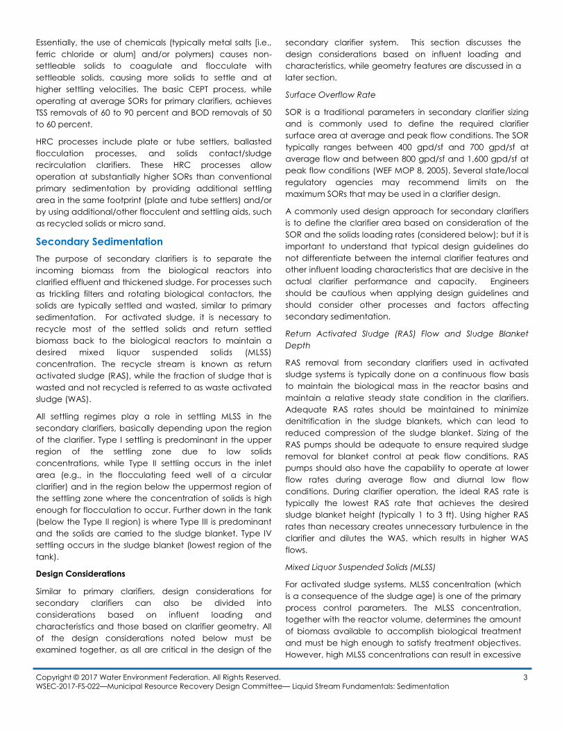
Center feed: Center feed clarifiers are the most common
configuration. In this case, the influent is fed through a
center column to a center feed well. Center feed clarifiers
are typically designed with a peripheral effluent overflow
[Figure 1].
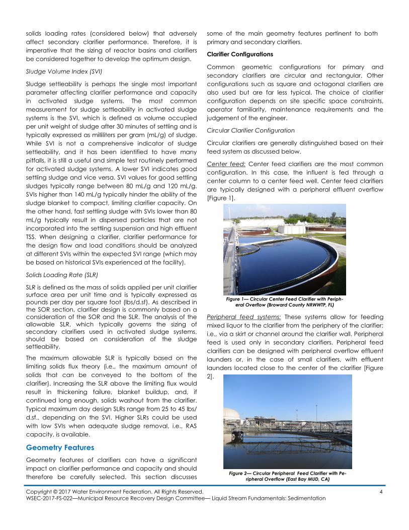
Peripheral feed systems: These systems allow for feeding
mixed liquor to the clarifier from the periphery of the clarifier;
i.e., via a skirt or channel around the clarifier wall. Peripheral
feed is used only in secondary clarifiers. Peripheral feed
clarifiers can be designed with peripheral overflow effluent
launders or, in the case of small clarifiers, with effluent
launders located close to the center of the clarifier [Figure
2].
Copyright © 2017 Water Environment Federation. All Rights Reserved. 4
WSEC-2017-FS-022—Municipal Resource Recovery Design Committee— Liquid Stream Fundamentals: Sedimentation
Figure 1— Circular Center Feed Clarifier with Periph-
eral Overflow (Broward County NRWWTP, FL)
Figure 2— Circular Peripheral Feed Clarifier with Pe-
ripheral Overflow (East Bay MUD, CA)
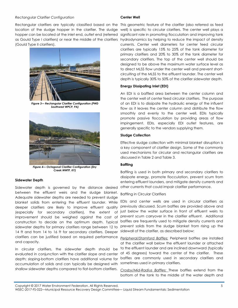
Rectangular Clarifier Configuration
Rectangular clarifiers are typically classified based on the
location of the sludge hopper in the clarifier. The sludge
hopper can be located at the inlet end, outlet end (referred
as Gould Type I clarifiers) or near the middle of the clarifiers
(Gould Type II clarifiers).
Sidewater Depth
Sidewater depth is governed by the distance desired
between the effluent weirs and the sludge blanket.
Adequate sidewater depths are needed to prevent sludge
blanket solids from entering the effluent launder. While
deeper clarifiers are likely to improve effluent quality
(especially for secondary clarifiers), the extent of
improvement should be weighed against the cost of
construction to decide on the optimum depth. Typical
sidewater depths for primary clarifiers range between 12 to
14 ft and from 14 to 16 ft for secondary clarifiers. Deeper
clarifiers can be justified based on required performance
and capacity.
In circular clarifiers, the sidewater depth should be
evaluated in conjunction with the clarifier slope and center
depth; sloping-bottom clarifiers have additional volume for
accumulation of solids and can typically be designed with
shallow sidewater depths compared to flat-bottom clarifiers.
Center Well
This geometric feature of the clarifier (also referred as feed
well) is specific to circular clarifiers. The center well plays a
significant role in promoting flocculation and improving tank
hydrodynamics by helping to reduce the impact of density
currents. Center well diameters for center feed circular
clarifiers are typically 15% to 25% of the tank diameter for
primary clarifiers and 20% to 30% of the tank diameter for
secondary clarifiers. The top of the center well should be
designed to be above the maximum water surface level as
to direct MLSS flow under the center well and prevent short-
circuiting of the MLSS to the effluent launder. The center well
depth is typically 30% to 50% of the clarifier sidewater depth.
Energy Dissipating Inlet (EDI)
An EDI is a baffled area between the center column and
the center well of center feed circular clarifiers. The purpose
of an EDI is to dissipate the hydraulic energy of the influent
flow as it leaves the center column and distribute the flow
smoothly and evenly to the center well. EDIs typically
promote passive flocculation by providing areas of flow
impingement. EDIs, especially EDI outlet features, are
generally specific to the vendors supplying them.
Sludge Collection
Effective sludge collection with minimal blanket disruption is
a key component of clarifier design. Some of the commonly
used mechanisms for circular and rectangular clarifiers are
discussed in Table 2 and Table 3.
Baffling
Baffling is used in both primary and secondary clarifiers to
dissipate energy, promote flocculation, prevent scum from
entering effluent launders, and mitigate density currents and
other currents that could impair clarifier performance.
Baffling in Circular Clarifiers
EDIs and center wells are used in circular clarifiers as
previously discussed. Scum baffles are provided above and
just below the water surface in front of effluent weirs to
prevent scum carryover in the clarifier effluent. Additional
baffles are frequently used to mitigate density currents and
prevent solids from the sludge blanket from rising up the
sidewall of the clarifier, as described below:
Peripheral/Stamford Baffles: Peripheral baffles are installed
at the clarifier wall below the effluent launder or attached
to the effluent launder and are inclined downward (typically
at 45 degrees) toward the center of the clarifier. These
baffles are commonly used in secondary clarifiers and
sometimes used in primary clarifiers.
Crosby/Mid-Radius Baffles: These baffles extend from the
bottom of the tank to the middle of the water depth and
Copyright © 2017 Water Environment Federation. All Rights Reserved. 5
WSEC-2017-FS-022—Municipal Resource Recovery Design Committee— Liquid Stream Fundamentals: Sedimentation
Figure 3— Rectangular Clarifier Configuration (PWD
Southwest WPCP, PA)
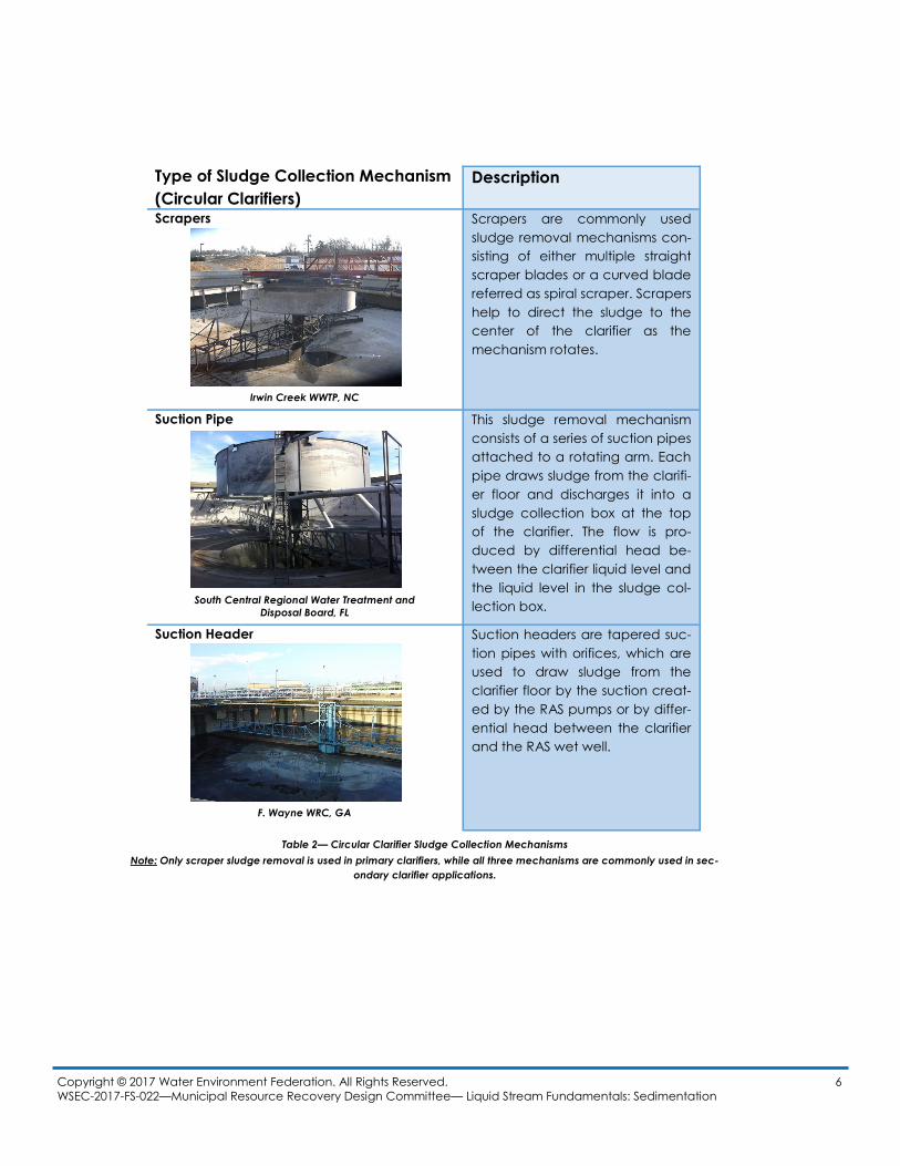
Figure 4— Octagonal Clarifier Configuration (Dry
Creek WWTP, KY)
Copyright © 2017 Water Environment Federation. All Rights Reserved. 6
WSEC-2017-FS-022—Municipal Resource Recovery Design Committee— Liquid Stream Fundamentals: Sedimentation
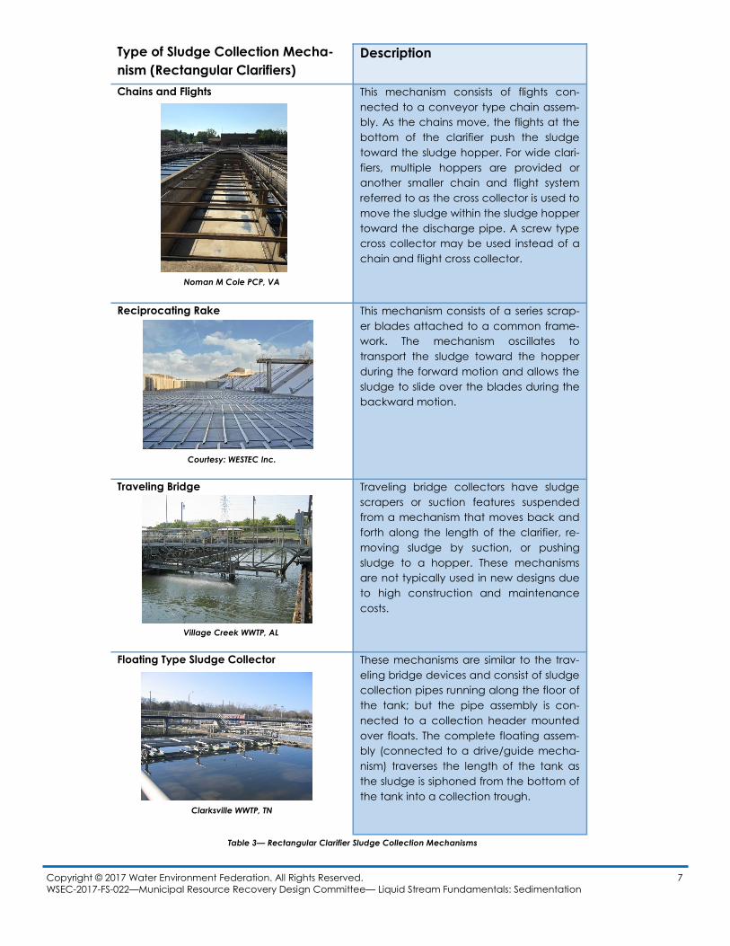
Type of Sludge Collection Mechanism
(Circular Clarifiers)
Description
Scrapers Scrapers are commonly used
sludge removal mechanisms con-
sisting of either multiple straight
scraper blades or a curved blade
referred as spiral scraper. Scrapers
help to direct the sludge to the
center of the clarifier as the
mechanism rotates.
Suction Pipe This sludge removal mechanism
consists of a series of suction pipes
attached to a rotating arm. Each
pipe draws sludge from the clarifi-
er floor and discharges it into a
sludge collection box at the top
of the clarifier. The flow is pro-
duced by differential head be-
tween the clarifier liquid level and
the liquid level in the sludge col-
lection box.
Suction Header Suction headers are tapered suc-
tion pipes with orifices, which are
used to draw sludge from the
clarifier floor by the suction creat-
ed by the RAS pumps or by differ-
ential head between the clarifier
and the RAS wet well.
Irwin Creek WWTP, NC
South Central Regional Water Treatment and
Disposal Board, FL
F. Wayne WRC, GA
Table 2— Circular Clarifier Sludge Collection Mechanisms
Note: Only scraper sludge removal is used in primary clarifiers, while all three mechanisms are commonly used in sec-
ondary clarifier applications.
Copyright © 2017 Water Environment Federation. All Rights Reserved. 7
WSEC-2017-FS-022—Municipal Resource Recovery Design Committee— Liquid Stream Fundamentals: Sedimentation
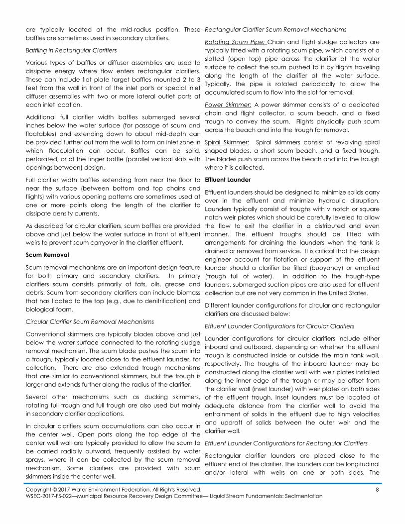
Type of Sludge Collection Mecha-
nism (Rectangular Clarifiers)
Description
Chains and Flights This mechanism consists of flights con-
nected to a conveyor type chain assem-
bly. As the chains move, the flights at the
bottom of the clarifier push the sludge
toward the sludge hopper. For wide clari-
fiers, multiple hoppers are provided or
another smaller chain and flight system
referred to as the cross collector is used to
move the sludge within the sludge hopper
toward the discharge pipe. A screw type
cross collector may be used instead of a
chain and flight cross collector.
Reciprocating Rake This mechanism consists of a series scrap-
er blades attached to a common frame-
work. The mechanism oscillates to
transport the sludge toward the hopper
during the forward motion and allows the
sludge to slide over the blades during the
backward motion.
Traveling Bridge Traveling bridge collectors have sludge
scrapers or suction features suspended
from a mechanism that moves back and
forth along the length of the clarifier, re-
moving sludge by suction, or pushing
sludge to a hopper. These mechanisms
are not typically used in new designs due
to high construction and maintenance
costs.
Floating Type Sludge Collector These mechanisms are similar to the trav-
eling bridge devices and consist of sludge
collection pipes running along the floor of
the tank; but the pipe assembly is con-
nected to a collection header mounted
over floats. The complete floating assem-
bly (connected to a drive/guide mecha-
nism) traverses the length of the tank as
the sludge is siphoned from the bottom of
the tank into a collection trough.
Noman M Cole PCP, VA
Courtesy: WESTEC Inc.
Village Creek WWTP, AL
Clarksville WWTP, TN
Table 3— Rectangular Clarifier Sludge Collection Mechanisms
are typically located at the mid-radius position. These
baffles are sometimes used in secondary clarifiers.
Baffling in Rectangular Clarifiers
Various types of baffles or diffuser assemblies are used to
dissipate energy where flow enters rectangular clarifiers.
These can include flat plate target baffles mounted 2 to 3
feet from the wall in front of the inlet ports or special inlet
diffuser assemblies with two or more lateral outlet ports at
each inlet location.
Additional full clarifier width baffles submerged several
inches below the water surface (for passage of scum and
floatables) and extending down to about mid-depth can
be provided further out from the wall to form an inlet zone in
which flocculation can occur. Baffles can be solid,
perforated, or of the finger baffle (parallel vertical slats with
openings between) design.
Full clarifier width baffles extending from near the floor to
near the surface (between bottom and top chains and
flights) with various opening patterns are sometimes used at
one or more points along the length of the clarifier to
dissipate density currents.
As described for circular clarifiers, scum baffles are provided
above and just below the water surface in front of effluent
weirs to prevent scum carryover in the clarifier effluent.
Scum Removal
Scum removal mechanisms are an important design feature
for both primary and secondary clarifiers. In primary
clarifiers scum consists primarily of fats, oils, grease and
debris. Scum from secondary clarifiers can include biomass
that has floated to the top (e.g., due to denitrification) and
biological foam.
Circular Clarifier Scum Removal Mechanisms
Conventional skimmers are typically blades above and just
below the water surface connected to the rotating sludge
removal mechanism. The scum blade pushes the scum into
a trough, typically located close to the effluent launder, for
collection. There are also extended trough mechanisms
that are similar to conventional skimmers, but the trough is
larger and extends further along the radius of the clarifier.
Several other mechanisms such as ducking skimmers,
rotating full trough and full trough are also used but mainly
in secondary clarifier applications.
In circular clarifiers scum accumulations can also occur in
the center well. Open ports along the top edge of the
center well wall are typically provided to allow the scum to
be carried radially outward, frequently assisted by water
sprays, where it can be collected by the scum removal
mechanism. Some clarifiers are provided with scum
skimmers inside the center well.
Rectangular Clarifier Scum Removal Mechanisms
Rotating Scum Pipe: Chain and flight sludge collectors are
typically fitted with a rotating scum pipe, which consists of a
slotted (open top) pipe across the clarifier at the water
surface to collect the scum pushed to it by flights traveling
along the length of the clarifier at the water surface.
Typically, the pipe is rotated periodically to allow the
accumulated scum to flow into the slot for removal.
Power Skimmer: A power skimmer consists of a dedicated
chain and flight collector, a scum beach, and a fixed
trough to convey the scum. Flights physically push scum
across the beach and into the trough for removal.
Spiral Skimmer: Spiral skimmers consist of revolving spiral
shaped blades, a short scum beach, and a fixed trough.
The blades push scum across the beach and into the trough
where it is collected.
Effluent Launder
Effluent launders should be designed to minimize solids carry
over in the effluent and minimize hydraulic disruption.
Launders typically consist of troughs with v notch or square
notch weir plates which should be carefully leveled to allow
the flow to exit the clarifier in a distributed and even
manner. The effluent troughs should be fitted with
arrangements for draining the launders when the tank is
drained or removed from service. It is critical that the design
engineer account for flotation or support of the effluent
launder should a clarifier be filled (buoyancy) or emptied
(trough full of water). In addition to the trough-type
launders, submerged suction pipes are also used for effluent
collection but are not very common in the United States.
Different launder configurations for circular and rectangular
clarifiers are discussed below:
Effluent Launder Configurations for Circular Clarifiers
Launder configurations for circular clarifiers include either
inboard and outboard, depending on whether the effluent
trough is constructed inside or outside the main tank wall,
respectively. The troughs of the inboard launder may be
constructed along the clarifier wall with weir plates installed
along the inner edge of the trough or may be offset from
the clarifier wall (inset launder) with weir plates on both sides
of the effluent trough. Inset launders must be located at
adequate distance from the clarifier wall to avoid the
entrainment of solids in the effluent due to high velocities
and updraft of solids between the outer weir and the
clarifier wall.
Effluent Launder Configurations for Rectangular Clarifiers
Rectangular clarifier launders are placed close to the
effluent end of the clarifier. The launders can be longitudinal
and/or lateral with weirs on one or both sides. The
Copyright © 2017 Water Environment Federation. All Rights Reserved. 8
WSEC-2017-FS-022—Municipal Resource Recovery Design Committee— Liquid Stream Fundamentals: Sedimentation
placement of the launders and weirs should take into
account the hydraulic patterns caused by the clarifier end
wall (referred to as the end wall effect) and the designer
should avoid the use of single launders to minimize the
impact of the end wall effect.
Irrespective of the launder type and configuration, selected
provisions to provide accessibility to the weirs/suction pipes
for routine maintenance and repairs should be included in
the design.
Effluent Launder Covers
Effluent launder covers are commonly used in primary and
secondary clarifier applications for odor management
(primary clarifiers) and to prevent algae growth. Launder
covers are very effective for the aforementioned purposes,
however, they impose a barrier for visualization of the
effluent quality in the effluent launder; and this is a limitation
that should be considered before implementation.
Instrumentation
While clarifiers are not instrumentation-intensive unit
processes, some instrumentation-based controls can be
useful for regulating and monitoring clarifier performance.
One of the most commonly used instrumentation devices
are sludge blanket readers/trackers (e.g. light emitting
analyzers, ultrasonic analyzers, optical sensors). Sludge
blanket measurement devices are mostly used in secondary
clarifiers but could also be used in primary clarifier
applications.
Instrumentation devices for monitoring clarifier drive torque,
power and motion, which are used for protection of the
clarifier drive gearbox and sludge collection mechanism,
are also a common in clarifier designs. Other instrumentation
options for clarifiers include mixed liquor/influent/effluent
flow meters, primary sludge flow meters, RAS and WAS flow
meters, and TSS probes.
Operation and Maintenance
Operation and control of clarifiers can range from
completely manual to completely automated. In either
scenario, the key operator responsibilities for clarifier
operation are controlling RAS/primary sludge flow rates to
maintain clarifier blankets and prevent solids carryover in
the effluent, especially during high flows. Additionally,
attention should be paid to monitoring flows, influent TSS,
effluent TSS, underflow (sludge) TSS, and SVI (when
applicable).
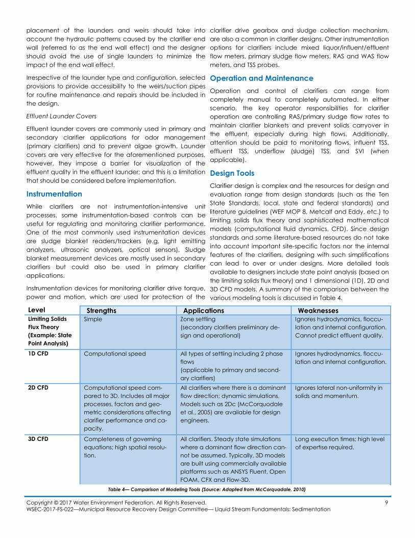
Design Tools
Clarifier design is complex and the resources for design and
evaluation range from design standards (such as the Ten
State Standards, local, state and federal standards) and
literature guidelines (WEF MOP 8, Metcalf and Eddy, etc.) to
limiting solids flux theory and sophisticated mathematical
models (computational fluid dynamics, CFD). Since design
standards and some literature-based resources do not take
into account important site-specific factors nor the internal
features of the clarifiers, designing with such simplifications
can lead to over or under designs. More detailed tools
available to designers include state point analysis (based on
the limiting solids flux theory) and 1 dimensional (1D), 2D and
3D CFD models. A summary of the comparison between the
various modeling tools is discussed in Table 4.
Copyright © 2017 Water Environment Federation. All Rights Reserved. 9
WSEC-2017-FS-022—Municipal Resource Recovery Design Committee— Liquid Stream Fundamentals: Sedimentation
Level Strengths Applications Weaknesses Limiting Solids
Flux Theory
(Example: State
Point Analysis)
Simple Zone settling
(secondary clarifiers preliminary de-
sign and operational)
Ignores hydrodynamics, floccu-
lation and internal configuration.
Cannot predict effluent quality.
1D CFD Computational speed All types of settling including 2 phase
flows
(applicable to primary and second-
ary clarifiers)
Ignores hydrodynamics, floccu-
lation and internal configuration.
2D CFD Computational speed com-
pared to 3D. Includes all major
processes, factors and geo-
metric considerations affecting
clarifier performance and ca-
pacity.
All clarifiers where there is a dominant
flow direction; dynamic simulations.
Models such as 2Dc (McCorquodale
et al., 2005) are available for design
engineers.
Ignores lateral non-uniformity in
solids and momentum.
3D CFD Completeness of governing
equations; high spatial resolu-
tion.
All clarifiers. Steady state simulations
where a dominant flow direction can-
not be assumed. Typically, 3D models
are built using commercially available
platforms such as ANSYS Fluent, Open
FOAM, CFX and Flow-3D.
Long execution times; high level
of expertise required.
Table 4— Comparison of Modeling Tools (Source: Adapted from McCorquadale, 2010)
Copyright © 2017 Water Environment Federation. All Rights Reserved. 10
WSEC-2017-FS-022—Municipal Resource Recovery Design Committee— Liquid Stream Fundamentals: Sedimentation
References
• Ekama G. A.; Barnard, J. L.; Gunthert, F. W.; Krebs, P.;
McCorquodale, J. A.; Parker, D. S.; Wahlberg, E. J. (1997)
Secondary Settling Tanks: Theory, Modelling Design and
Operation, Scientific and Technical Report No.6;
International Association of Water Quality: London.
• Esler, J. K. (2000). Optimizing Clarifier Design and
Performance. Proceedings of the Water Environment
Federation, 2000(5), 1-10.
• Griborio, A., McCorquodale, J. A., & Rodriguez, J. A.
(2014). CFD modeling of primary clarifiers: the state-of-
the-art. Proceedings of the Water Environment
Federation, 2014(8), 1926-1949.
• Jeyanayagam, S. (2006). Design and Operation of Final
Clarifiers. Proceedings of the Florida Water Resources
Journal, January 2006.
• McCorquodale, J.A., Griborio, A., and Georgiou, I.
(2005). A Public Domain Settling Tank Model.
Proceedings Water Environment Federation 78th Annual
Conference & Exposition, Washington, D.C., Oct. 29 –
Nov. 2, pp. 2546-2561.
• McCorquodale (2010), Overview of the history and
state of modelling of sedimentation tanks, Presentaed
at WWTmod, Monte Sainte-Anne, Quebec.
• Tchobanoglous, G., Burton, F. L., & Stensel, H. D. Metcalf
& Eddy,(2003).". Wastewater Engineering: Treatment
and Reuse, 4.
• Water Environment Federation (2005) Design of
Municipal Wastewater Treatment Plants, Manual of
Practice No. 8 (WEF MOP 8); Second Edition; Water
Environment Federation: Alexandria, Virginia
Acknowledgments
WEF Municipal Resource Recovery Design Committee
Kristen Waksman & Ifetayo Venner (Liquid Stream
Fundamentals Fact Sheet Leads)
Contributing Authors:
Nandita Ahuja (Lead)
Alonso G. Griborio