Liquid Level Bin-Dicator Installation & Operation Manual
12
Liquid Level Bin-Dicator ® Installation & Operation Manual IOM LAG180420 Rev. E
Transcript of Liquid Level Bin-Dicator Installation & Operation Manual

Liquid Level Bin-Dicator®
Installation & Operation Manual
IOM
LAG
1804
20 R
ev. E

Liquid Level Bin-Dicator®
Installation & Operation Manual
CONTENTS
I. HANDLING & STORAGE .......................................................................................................................... 1 Inspection and Handling Disposal and Recycling Storage
II. GENERAL SAFETY ................................................................................................................................... 2 Authorized Personnel Use Misuse
III. PRODUCT DESCRIPTION ....................................................................................................................... 3 Function Features TechnicalSpecifications Approvals
IV. MECHANICAL INSTALLATION ................................................................................................................. 4 Guidelines Mounting
V. ELECTRICAL INSTALLATION .................................................................................................................. 5 General Safety Disconnect Requirements Wiring Diagram
VI. MAINTENANCE ........................................................................................................................................ 6 Replacement Parts
VII. DIMENSIONAL DRAWING ....................................................................................................................... 7

SAFETY SYMBOLS
WARNING:IDENTIFIES CONDITIONS OR PROCEDURES, WHICH IF NOT FOLLOWED, COULD RESULT IN SERIOUS INJURY. RISK OF ELECTRICAL SHOCK.
CAUTION:IDENTIFIES CONDITIONS OR PROCEDURES, WHICH IF NOT FOLLOWED, COULD RESULT IN SERIOUS DAMAGE OR FAILURE OF THE EQUIPMENT.

1
www.bindicator.com
LAG180420 Rev. E
Liquid Level Bin-Dicator®
I. HANDLING AND STORAGE
SAVE THESE INSTRUCTIONS
INSPECTION AND HANDLING
Do not dispose of the carton or packing materials.
Each package should be inspected upon receipt for damage that may have occurred due to mishandling during
shipping. If the unit is received damaged, notify the carrier or the factory for instructions. Failure to do so may
void your warranty. If you have any problems or questions, consult Customer Support at 1-800-778-9242.
DISPOSAL AND RECYCLING
This product can be recycled by specialized companies and must not be disposed of in a municipal collection
site. If you do not have the means to dispose of properly, please contact for return and disposal instructions or
options.
STORAGE
If the device is not scheduled for immediate installation following delivery, the following steps should be
observed:
1. Following inspection, repackage the unit into its original packaging.
2. Select a clean dry site, free of vibration, shock and impact hazards.
3. If storage will be extended longer than 30 days, the unit must be stored at temperatures between 32º and 158º F (0º to 70° C) in non-condensing atmosphere with humidity less than 85%.
CAUTION: DO NOT STORE A NON-POWERED UNIT OUTDOORS FOR A PROLONGED PERIOD.
2LAG180420 Rev. E
www.bindicator.com
II. GENERAL SAFETY
AUTHORIZED PERSONNEL
Allinstructionsdescribedinthedocumentmustbeperformedbyauthorizedandqualifiedservicepersonnel
only. Before installing the unit, please read these instructions and familiarize yourself with the requirements and
functions of the device. The required personal protective equipment must always be worn when servicing this
device.
USE
The device is solely intended for use as described in this manual. Reliable operation is ensured only if the
instrumentisusedaccordingtothespecificationsdescribedinthisdocument.Forsafetyandwarrantyreasons,
useofaccessoryequipmentnotrecommendedbythemanufacturerormodificationofthisdeviceisexplicitly
forbidden.Allservicingofthisequipmentmustbeperformedbyqualifiedservicepersonnelonly.Thisdevice
should be mounted in locations where it will not be subject to tampering by unauthorized personnel.
MISUSE
Improper use or installation of this device may cause the following:
• Personalinjuryorharm
• Applicationspecifichazardssuchasvesseloverfill
• Damagetothedeviceorsystem
If any questions or problems arise during installation of this equipment, please contact Customer Support at
800-778-9242.

3
www.bindicator.com
LAG180420 Rev. E
III. PRODUCT DESCRIPTION
FUNCTION
Non-ContactLiquidLevelBin-Dicatorcontrolisalowcost,floatless,pressuresensitive,diaphragmactuated
switchthatautomatesthefillingandemptyingofcontainers.
FEATURES
• Actuatesoverflowandlowlevelalarms
• Indicateshighand/orlowliquidlevels
• Optionalsidemounting
TECHNICAL SPECIFICATIONS
Housing and CoverPolyester Coated Aluminum Casting
OptionalExplosion-Proof
Pressure Chamber Polyester Coated Aluminum Casting 1” NPT
Diaphragm Teflon® Faced Neoprene
Switch
Standard SPDT Snap Action Switch (Dry Contact) Rated: 15 amp resistive @ 125, 250 or 480 VAC, Pilot Duty 375 VA, 125 VAC or 750 VA, 250 VAC
Shipping Weight 7 lbs (3 kg)
Temperature Rating 32° to 158° F (0° to +70° C)
Pollution Degree 2
Installation Category II
Altitude 6,562 ft (2000 m)
Note: Forhighandlowlevelfloatcontrol,BindicatoroffersLevelitefloatcontrollers.Visit www.levelitestore.com for more information.
APPROVALS
GT-1: UL (US) - General Purpose CSA - General PurposeGTX-1: UL (US) - Hazardous Location for Class 1, Groups C and D; Class II, Groups E, F and G CSA - Hazardous Location for Class I, Groups C and D; Class II, Groups E, F and G Intrinsically Safe
4LAG180420 Rev. E
www.bindicator.com
IV. MECHANICAL INSTALLATION
CAUTIONS: WARNING: REMOVE POWER FROM THE UNIT BEFORE INSTALLING, REMOVING, OR
MAKING ADJUSTMENTS.
GUIDELINES
- Inlieuoffieldtestingpriortoinstallation,thefollowingmaybeusedasageneralguidebasedontestswith water temperature at 65º F (18º C).
- High Level Switch Actuation: Allow for level to rise 5 in (13 cm) above the riser inlet. Add 1 in (2.54 cm) to the High Level Switch Actuation point for each additional 10 ft (3 m) of vertical riser pipe.
NOTE: The above guide allows for differences between individual production units. When using a single unit
for high-low operation, the level differential will be approximately 2 in (5.02 cm).
MOUNTING
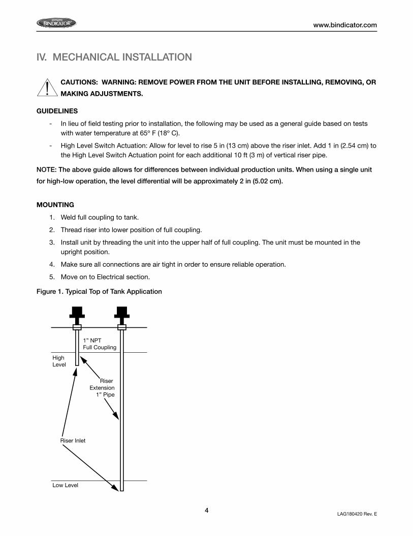
1. Weld full coupling to tank.
2. Thread riser into lower position of full coupling.
3. Install unit by threading the unit into the upper half of full coupling. The unit must be mounted in the upright position.
4. Make sure all connections are air tight in order to ensure reliable operation.
5. Move on to Electrical section.
Figure 1. Typical Top of Tank Application
Riser Inlet
High Level
Low Level
Riser Extension
1” Pipe
1” NPTFull Coupling
5
www.bindicator.com
LAG180420 Rev. E
V. ELECTRICAL INSTALLATION
WARNING: VERY HIGH VOLTAGE IS PRESENT. REMOVE POWER FROM THE UNIT BEFORE
INSTALLING, REMOVING, OR MAKING ADJUSTMENTS
GENERAL SAFETY
When using electrical equipment, you should always follow basic safety precautions, including the following:
• Theinstallationandwiringofthisproductmustcomplywithallnational,federal,state,municipal,andlocal codes that apply.
• Properlygroundtheenclosuretoanadequateearthground.
• Do not modify any factory wiring. Connections should only be made to the terminals described in this section.
• Allconnectionstotheunitmustuseconductorswithaninsulationratingof300Vminimum,ratedfor105C,aminimumflammabilityratingofVW-1,andbeofappropriategaugeforthevoltageandcurrentrequired(seespecifications).
• Donotallowmoisturetoentertheelectronicsenclosure.Conduitshouldslopedownwardfromtheunit
housing. Install drip loops and seal conduit with silicone rubber product.
DISCONNECT REQUIREMENTS FOR PERMANENTLY INSTALLED EQUIPMENT
A dedicated disconnecting device (circuit breaker) must be provided for the proper installation of the unit. If
independent circuits are used for power input and outputs, individual disconnects are required.
Disconnects must meet the following requirements:
• Locatedincloseproximitytothedevice
• Easilyaccessibletotheoperator
• Appropriatelymarkedasthedisconnectforthedeviceandassociatedcircuit
• Sizedappropriatelytotherequirementsoftheprotectedcircuit(Seespecifications)
PROTECTIVE EARTH GROUND
To eliminate shock hazards in the unlikely event of an internal insulation breakdown, the unit is provided with a
“protective earth” ( ) lead which must be connected to earth ground. In addition, the input power ground
lead must be connected to the “protective earth” ( ) terminal provided. Wire sizes must be selected such that
it can safely carry the sum total of all circuits’ maximum amperage.

6LAG180420 Rev. E
www.bindicator.com
WIRING DIAGRAM
Figure 2. Typical Wiring Diagram
VI. MAINTENANCE
No scheduled preventative maintenance is required when unit is properly applied and installed correctly. There is
no cleaning required for the unit before or during installation.
REPLACEMENT PARTS
PART NUMBER DESCRIPTION
LAG110760 Micro Switch Assembly
LAG110800 Cam Assembly
LAG121700 Cover, Cast Aluminum
LAG121750 Switch Barrier
LAG121760 Push Rod, Stainless Steel with Lock Ring #9120
LAG121780 Diaphragm Back Plate, Aluminum
LAG121790 TeflonOverNeopreneDiaphragm
LAG121820 Brass Vent
LAG121830 Switch Bracket
LAG131150 Micro Switch, 180°F (82°C), BA-2RB-A4 Plunger
In this wiring arrangement the high level signal is on when the tank is full.
When the level of material is between the high and low levels, all signals are off.
When the tank is empty, the low level signal is on.
As the liquid level approaches the low level riser inlet, the pump motor will automatically start. The pump will continue to run until the liquid level reaches and rises above the high level riser inlet, at which time the pump is automatically stopped.
The pump will remain stopped until the liquid level approaches the low level and the cycle is repeated.

7
www.bindicator.com
LAG180420 Rev. E
VII. DIMENSIONAL DRAWING
5.75”146 mm
7.75
”19
7 m
m
3.0”
76 m
m
1” NPT
150 Venture Boulevard Spartanburg, SC 29306Tel: (800) 778-9242 Fax: (864) [email protected]
2013 All rights reserved.All data subject to change without notice.
LAG180420 Rev. E


![LUXEON Z - Mouser Electronics · Bin 3U[1] Bin 3L[2] Bin 5A Bin 5B Bin 5C Bin 5D NOTE: Color bin space illustration for 2700K, 3000K and 3500K. For CCT above 4000K, the ellipse centers](https://static.fdocuments.in/doc/165x107/5e7f177fcf08133c0416f5d3/luxeon-z-mouser-electronics-bin-3u1-bin-3l2-bin-5a-bin-5b-bin-5c-bin-5d-note.jpg)

![Triphenylene discotic liquid crystal trimers …...2852 Triphenylene discotic liquid crystal trimers synthesized by Co2(CO)8-catalyzed terminal alkyne [2 + 2 + 2] cycloaddition Bin€Han1,](https://static.fdocuments.in/doc/165x107/5f47f6c084005e2ca618fc1f/triphenylene-discotic-liquid-crystal-trimers-2852-triphenylene-discotic-liquid.jpg)