Liquid Cooling Integration and Logistics White Pap e r
24
This work is licensed under a Creative Commons Attribution-ShareAlike 4.0 International License. Liquid Cooling Integration and Logistics White Paper Revision 1.0 CONTRIBUTOR(S): Michael, Gonzalez (CEJN), Conrad Wächter, Tommy Brill (CLOUD&HEAT), Jeff Grau, Tim Marquis (Parker), Mathew Archibald, Scott Stammer (Nvent) Cam Turner, (CoolIT), Glenn Charest, John Fernandes (Facebook), Nigel Gore, (Vertiv), Chris Lee, Simon Chen (Wiwynn)
Transcript of Liquid Cooling Integration and Logistics White Pap e r

This work is licensed under a Creative Commons Attribution-ShareAlike 4.0 International License.
Liquid Cooling Integration and Logistics White Paper Revision 1.0
CONTRIBUTOR(S):
Michael, Gonzalez (CEJN), Conrad Wächter, Tommy Brill (CLOUD&HEAT),
Jeff Grau, Tim Marquis (Parker), Mathew Archibald, Scott Stammer (Nvent)
Cam Turner, (CoolIT), Glenn Charest, John Fernandes (Facebook),
Nigel Gore, (Vertiv), Chris Lee, Simon Chen (Wiwynn)

Page 2
Open Compute Project Liquid Cooling Logistics and Integration White Paper
Executive Summary This document focuses on Technology Cooling System (TCS) liquid cooling infrastructure integration and logistics for the data center. The authors provide general guidance on server manufacturing levels, transportation, guidance on system integration and commissioning best practices. The document also provides steps required for data center installation and commissioning to provision liquid cooled racks ready for operation.
Page 3
Open Compute Project Liquid Cooling Logistics and Integration White Paper
Table of Contents
Executive Summary 2 Introduction 4 License 5 Revision History 5 1. Terminology 6
1.1 Server Manufacturing level ................................................................................................. 7 2. Manufacturing 9
2.1 Rack Integration – from L1 to L10 ....................................................................................... 9 2.2 Rack Integration – from L10 to L11 ................................................................................... 10 2.3 L10/L11 System Shipped without fluid .............................................................................. 11
3. Transportation 13 3.1 Manifold preparation ......................................................................................................... 13 3.2 Cold Plate preparation ...................................................................................................... 13 3.3 Packaging for transport .................................................................................................... 14
4. Rack Integration 16 5. DC Integration 18
5.1 Delivery ............................................................................................................................ 18 5.2 Inspection ........................................................................................................................ 18 5.3 Preparation ...................................................................................................................... 19
6. Install, Commissioning, Operate, Decommission 20 6.1 Preconditions for installation ............................................................................................. 20 6.2 Installation ........................................................................................................................ 20 6.3 Commissioning process for cooling infrastructure ............................................................. 21 6.4 Operation ......................................................................................................................... 22 6.5 Decommission.................................................................................................................. 23 6.6 Reuse Preparation ........................................................................................................... 23
7. About Open Compute Project 23 8. References 24

Page 4
Open Compute Project Liquid Cooling Logistics and Integration White Paper
Introduction This document outlines guidance for liquid cooling integration and logistics when deploying liquid cooled Information Technology Equipment (ITE) and Racks in a data center facility. This document considers that the technology has been chosen and readers require insight into the life cycle considerations for liquid cooling infrastructure.
Liquid cooling using cold plates cooling technologies has been the focus of many technology papers and industry guidelines. It is known that liquid cooling is an efficient and effective cooling fluid for high power and power dense solutions. The techniques for Liquid cooling ITE have been around since the 80s, the technology is evolving from mostly proprietary and limited interoperability to expanded offerings available from multiple vendors. Up until now best practices have been vendor specific the authors aim to disclose best practices and guidance on the integration of liquid cooling infrastructure into the data center. Robust supply chain systems are required, and sections dedicated to manufacturing, transport and integration activities are included within this document.
A comprehensive overview of ITE manufacturing stages is covered in detail including cold plate and manifold integration with a focus on quality assurance activities. Economic drivers including new delivery methods for fully integrated rack solutions are options for cost effective deployments. The authors have focused on positive pressure liquid cooling including water with glycol-based additives.
This document builds on the “ACS liquid cooling cold plate requirements” document, the “Cold Plate: Leak Detection and Intervention White Paper” & “Hose and Manual Couplings best practices White Paper” generated by the Advanced Cooling Solution (ACS) cold plate community. The document is focused on liquid cooling integration specifically within the Technology Cooling System (TCS), which includes cooling components such as cold plates, rack manifolds, Coolant Distribution Unit (CDU, end of row, or in rack CDUs), heat exchangers, hoses, and couplings.
Page 5
Open Compute Project Liquid Cooling Logistics and Integration White Paper
License
This work is licensed under a Creative Commons Attribution-ShareAlike 4.0 International License.
Revision History
Revision Date Comments
1.0 23 June Released for publication
Page 6
Open Compute Project Liquid Cooling Logistics and Integration White Paper
1. Terminology Couplings: A device that used to connect pipework of the same or different diameter. Couplings can reduce flow and require special consideration with the fluid flow network to ensure appropriate design.
Coolant Distribution Units (CDU): The Coolant Distribution Unit, CDU, provides an isolated cooling loop to the ITE. Heat transfer occurs inside the CDU, via a heat exchanger, between the heated liquid from the ITE loop (TCS) and the facility liquid (FWS) on the facility side. There is no coolant flow between the TCS and the FWS.
Conductive fluids: Coolant fluids that are capable of conducting electric current where both negative and positive particles are present. Variances in fluid conductivity depend on the ionic strength and temperature, increased temperature increases conductivity measured in Siemens per meter (S/m) alternatively milli-Siemens per centimeter (mS/cm).
Facility Water System (FWS): The liquid circuit that allows the transport of heat from the CDU out to the facility cooling infrastructure and back to the CDU. The facility cooling infrastructure could include chillers, cooling towers, economizers, and evaporative coolers. Commonly referred to in the Datacom space as Primary cooling loop and is typically measured in m3/s, liters per minute (LPM), or gallons per minute (GPM).
Field Replaceable Units (FRU): The parts of a product that can be easily removed and replaced where needed by a field service engineer without the entire system being replaced or returned to a repair center.
Forming Gas: A mixture of hydrogen and nitrogen and supports the removal of moisture and oxygen, other uses for forming gas include applications in microchip production. The gas is colorless, odorless, flammable, asphyxiant gas mixture, compressed, lighter than air.
Heat exchanger: For the purpose of heat transfer between two isolated liquid circuits and prevents mixing. Flow arrangement of fluids can be counter-flow where liquid passes from opposite ends or parallel-flow where liquids travel in parallel in the same direction. Information Technology Equipment (ITE): The computational servers, connectivity, networking and communication devices, data storage found in the data center and typically contained in racks. Manifold: A device that distributes cooling liquid from a central pipe to multiple smaller pipes, alternatively from multiple to one, and can be located with the CDU, at the row-level or inside the rack. The cooling liquid requires two-way transport called supply and return.
L1-12: Description of composition of components within Server manufacturing with reference to Server manufacturing levels which are reference by system integrators.
Pipework: Contains liquid and allows the transport of liquid, typically cylindrical and connected to form a system. Materials used for data center liquid cooling require strict adherence to wetted materials compatibility and support for flow rate and pressures based on design requirements.
Pipework Design: The integrity of pipework starts off with design requirements which include multiple components such as; spatial requirements, minimizing frictional points, pipe diameter, pipe joints, isolation, condensation, cost, heat load, and cooling duty, building codes including seismic and regulatory compliance.
Reservoir and pumping unit (RPU): An in-rack unit that provides make up liquid to the secondary fluid network devices, includes pumps but no heat exchanger.
Rear Door Heat Exchanger (RDHX): Rear Door Heat Exchanger is a type of liquid cooling configuration where heat exchanging modules are rack-mounted on the back side of the racks. System Integrator (SI): An organization specializing in bringing together component sub systems to form a functioning system.
Page 7
Open Compute Project Liquid Cooling Logistics and Integration White Paper
Shock and Vibration testing (S&V): Testing to examine response of system to defined testing parameters to simulate handling environments.
Technology Cooling System (TCS): The liquid circuit from the Coolant Distribution Unit (CDU) to the rack, through the manifold and the ITE, and then back through the return manifold to the CDU. Commonly referred to in the Datacom space as Secondary cooling loop.
Uninterruptible power supply (UPS): An electrical apparatus that provides emergency power when input power fails.
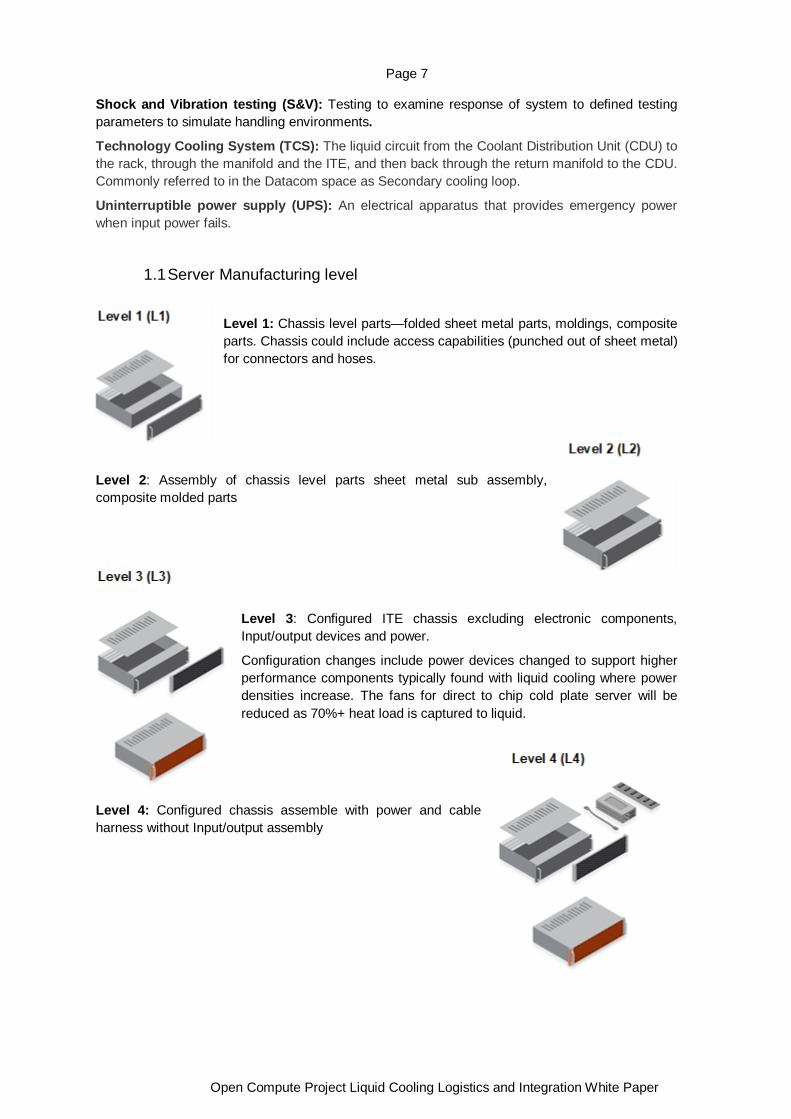
1.1 Server Manufacturing level
Level 1: Chassis level parts—folded sheet metal parts, moldings, composite parts. Chassis could include access capabilities (punched out of sheet metal) for connectors and hoses.
Level 2: Assembly of chassis level parts sheet metal sub assembly, composite molded parts
Level 3: Configured ITE chassis excluding electronic components, Input/output devices and power.
Configuration changes include power devices changed to support higher performance components typically found with liquid cooling where power densities increase. The fans for direct to chip cold plate server will be reduced as 70%+ heat load is captured to liquid.
Level 4: Configured chassis assemble with power and cable harness without Input/output assembly
Page 8
Open Compute Project Liquid Cooling Logistics and Integration White Paper
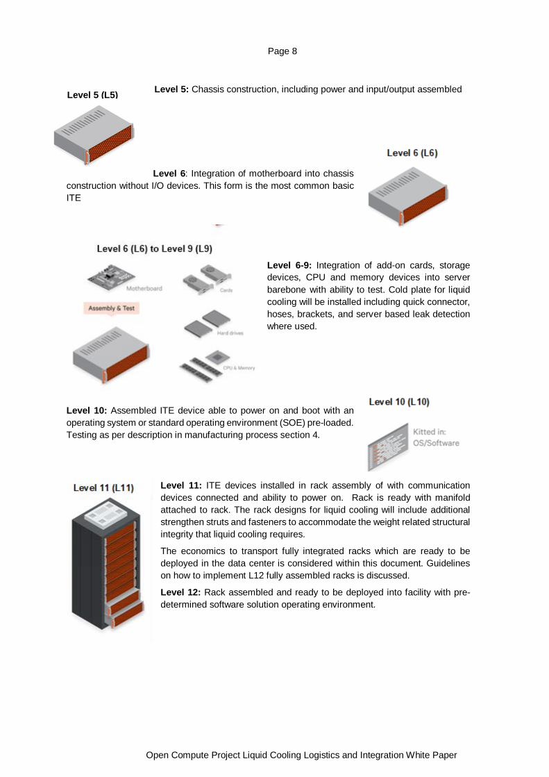
Level 5: Chassis construction, including power and input/output assembled
Level 6: Integration of motherboard into chassis construction without I/O devices. This form is the most common basic ITE
Level 6-9: Integration of add-on cards, storage devices, CPU and memory devices into server barebone with ability to test. Cold plate for liquid cooling will be installed including quick connector, hoses, brackets, and server based leak detection where used.
Level 10: Assembled ITE device able to power on and boot with an operating system or standard operating environment (SOE) pre-loaded. Testing as per description in manufacturing process section 4.
Level 11: ITE devices installed in rack assembly of with communication devices connected and ability to power on. Rack is ready with manifold attached to rack. The rack designs for liquid cooling will include additional strengthen struts and fasteners to accommodate the weight related structural integrity that liquid cooling requires.
The economics to transport fully integrated racks which are ready to be deployed in the data center is considered within this document. Guidelines on how to implement L12 fully assembled racks is discussed.
Level 12: Rack assembled and ready to be deployed into facility with pre-determined software solution operating environment.
Level 5 (L5)

Page 9
Open Compute Project Liquid Cooling Logistics and Integration White Paper
2. Manufacturing Figure 1- L10 server manufacturing workflow
2.1 Rack Integration – from L1 to L10 This section discusses the server manufacturing workflow to integrate and test cold plate assembles and prepare for shipment. The section references the figure above which illustrates the workflow to server manufacturing level 10. For detailed description on server manufacturing levels see glossary.
1. It is assumed that the cold plate module includes cold plates, liquid tubing and quick connectors that have been assembled as a complete package. Outgoing quality control reports (or incoming reports called by system integrator) are recommended to be provided by cold plate module vendors.
2. When an L10 system integrator receives the module, visual inspection is suggested to screen out and any visible damage on the module, before being assembled into the chassis. In order to not cause damages, it is recommended to follow the manufacturers’ torque requirement when tightening up the cold plates onto the CPUs/GPUs or any critical components of interest.
3. Forming gas is used for L10 level leakage detection is strongly recommended to be conducted to ensure quality is assured.
4. After the gaseous test, the L10 system is primed and filled up with the liquid, in the same composition of the end usage.
5. The system, which is filled with fluid, is then installed in a test rack and made ready for the L10 system test.
6. The L10 system test (also called final witness test, factory witness test or manufacturing test) is client dependent testing, meaning that the test items depend on deployment specific requests. Liquid-leakage-relevant testing is one of the tests that is recommended, which is
Page 10
Open Compute Project Liquid Cooling Logistics and Integration White Paper
different from servers under air cooling configuration. Appropriate stress tools, capable of fully exercising CPUs/GPUs (any other critical components in liquid cooling configuration), that simulates realistic on-site workload are suggested.
7. Before being packaged and shipped (9 and 10), the L10 system that passes the required test will be unloaded from the test rack.
8. Depending on the requirement the system can either retain the fluid and be packaged ready for transport alternatively drain the fluid prior to packaging and shipment.
It should be noted that: when servers are shipped out to the end users as L10 FRU (field replacement
units) parts (see notes “Ship to DC as L10 FRU part” in Figure 1), the package design needs to
satisfy the end users’ requirement. Where liquid is inside the conduit, a label with clear description
is needed. During the design phase, any shock and vibration testing designed to simulate the operation/shipment condition of the L10 system should consider the existence of fluid in the system.
For certain cases where the package may experience extreme ambient conditions, the composition
of liquid shipped with the L10 system should be carefully chosen to avoid a freeze event when the
ambient is below the freezing point.
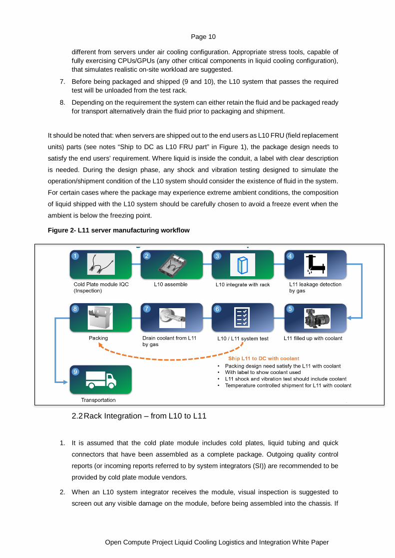
Figure 2- L11 server manufacturing workflow
2.2 Rack Integration – from L10 to L11
1. It is assumed that the cold plate module includes cold plates, liquid tubing and quick
connectors that have been assembled as a complete package. Outgoing quality control
reports (or incoming reports referred to by system integrators (SI)) are recommended to be
provided by cold plate module vendors.
2. When an L10 system integrator receives the module, visual inspection is suggested to screen out any visible damage on the module, before being assembled into the chassis. If

Page 11
Open Compute Project Liquid Cooling Logistics and Integration White Paper
an L11 manufacturer receives servers that have the L10 assembly readiness, steps (1) and
(2) can be skipped.
3. Different from L10 manufacturing, servers (L10) are uploaded to the rack (L11) for gaseous leakage detection.
4. L11 level leakage detection, including, but not limited to, servers, RDHX, RPU, manifold is
recommended to be conducted.
5. After the gaseous test, the rack is primed and filled up with the fluid, in the same composition of the end usage, made ready for the L11 system test.
6. The L11 system test (also called final witness test, factory witness test and manufacturing
test is client dependent testing, meaning that the test items depend on what end users’
requests.
7. Before being packaged and shipped to clients (8 and 9), the rack can either remain filled with liquid and packaged (dashed route), or (7) without the fluid (drained from the cold plate
by gas).
Some integrators may prefer to receive cold plate modules from their vendors that have been filled
with coolant. This allows cold plate vendors to perform additional tests during manufacturing such
as hydrostatic pressure testing, flow characterization and elevated temperature burn in. This also
reduces the amount of coolant required that the integrator must stock. If this method is chosen, steps 3 and 4 above are skipped. The leak test is a simple visual inspection.
It should be noted that: when racks are shipped out to the end users (see notes “Ship L11 to DC
with fluid” in Figure 3), the package design needs to satisfy the end users’ requirement. If fluid exists
inside the conduit, the manifold and the RPU or in-rack CDU, a label with clear description is needed.
During the design phase, any shock and vibration testing that simulates the operation/shipment
condition of the L11 system should consider the existence of fluid in the system. For those designs
with row-based components (e.g. centralized CDU) one should consider the connecters or tubing that are included in the shipping package in the corresponding DOE. For certain cases where the
package may experience extreme ambient conditions, the composition of fluid shipped in rack level
should be carefully chosen in order not to freeze when the ambient is below the freezing point, and
not to boil (unusual) when the ambient is above the boiling point.
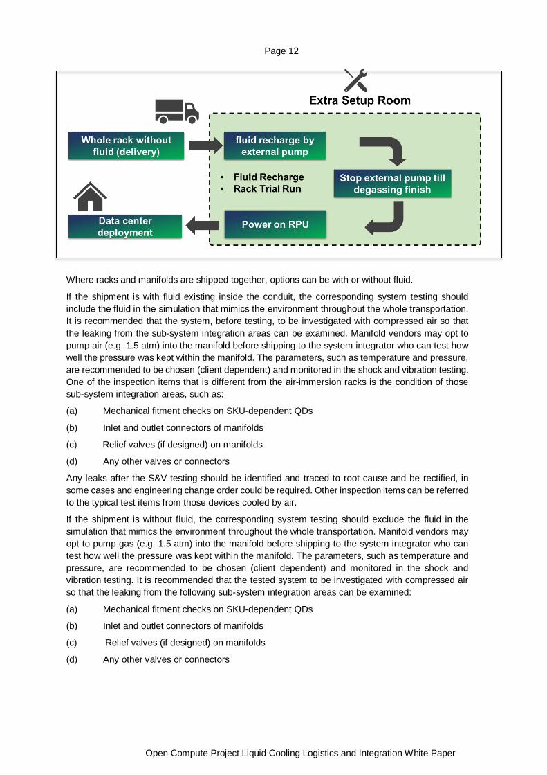
2.3 L10/L11 System Shipped without fluid When the packaging and shipping is chosen or required to be without liquid, there will be additional
process needed at the destination (data center). It is recommended to have an extra setup room for
fluid recharge and rack trial run before deploying to data center. This is to prevent contaminating
data centers with unexpected liquid leakage and damage to adjacent equipment. A quality inspection
to confirm gas has not leaked from the system is required prior to fill, signs of gas leak indicate
possible leak and should be tested further prior to filling with liquid.
Figure 3- L 11 rack-level integration delivery without fluid
Page 12
Open Compute Project Liquid Cooling Logistics and Integration White Paper
Where racks and manifolds are shipped together, options can be with or without fluid.
If the shipment is with fluid existing inside the conduit, the corresponding system testing should include the fluid in the simulation that mimics the environment throughout the whole transportation. It is recommended that the system, before testing, to be investigated with compressed air so that the leaking from the sub-system integration areas can be examined. Manifold vendors may opt to pump air (e.g. 1.5 atm) into the manifold before shipping to the system integrator who can test how well the pressure was kept within the manifold. The parameters, such as temperature and pressure, are recommended to be chosen (client dependent) and monitored in the shock and vibration testing. One of the inspection items that is different from the air-immersion racks is the condition of those sub-system integration areas, such as:
(a) Mechanical fitment checks on SKU-dependent QDs
(b) Inlet and outlet connectors of manifolds
(c) Relief valves (if designed) on manifolds
(d) Any other valves or connectors
Any leaks after the S&V testing should be identified and traced to root cause and be rectified, in some cases and engineering change order could be required. Other inspection items can be referred to the typical test items from those devices cooled by air.
If the shipment is without fluid, the corresponding system testing should exclude the fluid in the simulation that mimics the environment throughout the whole transportation. Manifold vendors may opt to pump gas (e.g. 1.5 atm) into the manifold before shipping to the system integrator who can test how well the pressure was kept within the manifold. The parameters, such as temperature and pressure, are recommended to be chosen (client dependent) and monitored in the shock and vibration testing. It is recommended that the tested system to be investigated with compressed air so that the leaking from the following sub-system integration areas can be examined:
(a) Mechanical fitment checks on SKU-dependent QDs
(b) Inlet and outlet connectors of manifolds
(c) Relief valves (if designed) on manifolds
(d) Any other valves or connectors

Page 13
Open Compute Project Liquid Cooling Logistics and Integration White Paper
Check for leaks after the S&V testing should follow design requirements. Other inspection items can be referred to the typical test items from those on air-cooled racks.
Altitude and lower pressure may be result, pressure decay could be a result in change of altitude which is possible and will be evident compared to system integrity issue which is an entire pressure loss.
3. Transportation
This section discusses the preparation of the liquid manifolds and cold plates to enable transport by alternate mode of transport, this includes packaging.
Packaging design to consider the product placement, evaluation and test, protection requirements and transportation support e.g. fork lift slots. The efficiency of design encompasses the packaging footprint is constructed to allow for the highest volume of product in the least amount of spatial volume to be cost effective. Packaging design is an engineering discipline and includes structural analysis, thermal analysis, regulatory requirements and expected use life.
3.1 Manifold preparation Preparation for transport follows the inspection and QA process. The manifold is prepared by flushing test fluid and particles from the internal chamber to prevent fouling or scaling whilst the manifold is in storage and transport prior to installation. The flushing process follows manufacturers guidelines and includes selection of flushing liquid and setting the rate of flow, the pressure and duration.
Once flushing is complete the manifold is to be drained of any remaining liquid with a minimal allowable remaining moisture rate following manufacturers guidelines. The chamber is sealed with a charge of Nitrogen at pressure in line with manufacturers recommended guidelines (PSI) to prepare for shipping and allowable storage duration. The chamber is sealed with end caps designed to completely seal the manifold ports. Strict adherence to safety data sheets for handling instruction provided by manufacturer and mode of transport to be validated e.g. Restrictions on air transport.
In some cases, manifolds may be shipped charged with coolant. This is done to reduce the amount of coolant required onsite and to reduce the amount of time required to commission the rack at the installation site. The manufacturer should clearly label the coolant type and charge date and provide test records proving that the appropriate temperature testing has been done to ensure that if the coolant freezes no damage will occur.
3.2 Cold Plate preparation Preparation for transport follows the inspection and QA process. The cold plate is prepared by flushing test fluid and particles from the internal fins to prevent fouling or scaling whilst the cold plate is in storage and transport prior to operation. The flushing process includes selection of flushing liquid and setting the rate of flow, direction, pressure and duration.
Once flushing is complete the cold plate is to be drained of any remaining liquid with a minimal allowable remaining moisture rate following manufacturers guidelines. The fin chamber is sealed with a charge of Nitrogen to prepare for shipping. The cold plate is sealed with end caps designed to completely seal the cold plate ports. Strict adherence to safety data sheets for handling instruction provided by manufacturer and mode of transport to be validated.
As with manifolds, in some cases the cold plate assemblies may be shipped charged with coolant. This is done to reduce the amount of coolant required onsite and to reduce the amount of time required to commission the rack at the installation site. The manufacturer should clearly label the coolant type and charge date on the cold plate and provide test records proving that the appropriate temperature testing has been done to ensure that if the coolant freezes no damage will occur.
Page 14
Open Compute Project Liquid Cooling Logistics and Integration White Paper
3.3 Packaging for transport Packaging for transport is an engineering effort and should be considered as part of the stakeholder requirements with the early development stages of product development. Incorrect packaging can cause damage, personal injury or death and should follow strict development testing. Packaging engineers will require a defined set of requirements to prepare appropriate packaging that will protect the contents and ensure that quality is assured from factory to installation site. The Packaging design will also have cost implications where the design is not compact additional freight charges will be incurred. The packaging should include considerations for how the contents will be carried from factory through to destination and include suitable slots for hand or mechanical lifting methods.
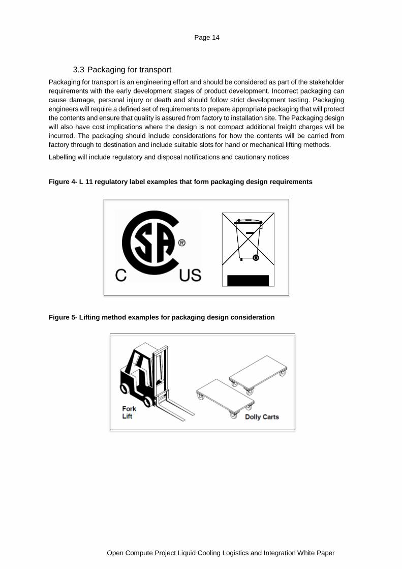
Labelling will include regulatory and disposal notifications and cautionary notices
Figure 4- L 11 regulatory label examples that form packaging design requirements
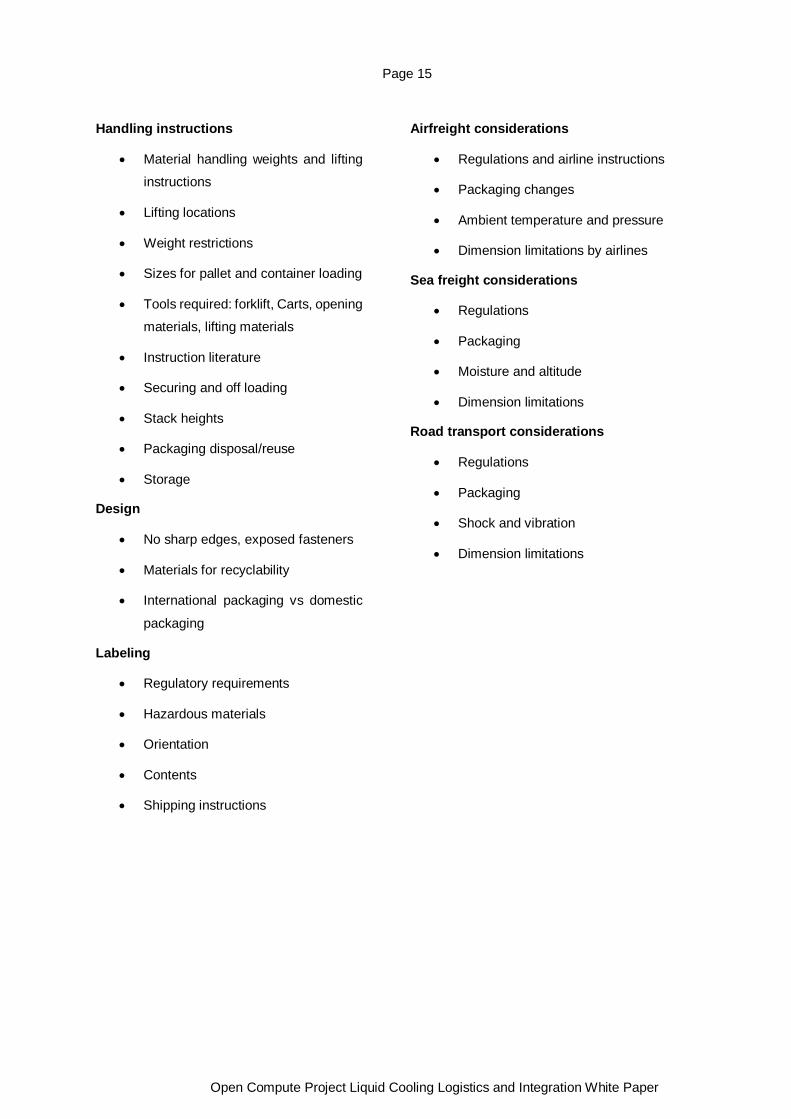
Figure 5- Lifting method examples for packaging design consideration
Page 15
Open Compute Project Liquid Cooling Logistics and Integration White Paper
Handling instructions
• Material handling weights and lifting instructions
• Lifting locations
• Weight restrictions
• Sizes for pallet and container loading
• Tools required: forklift, Carts, opening materials, lifting materials
• Instruction literature
• Securing and off loading
• Stack heights
• Packaging disposal/reuse
• Storage
Design
• No sharp edges, exposed fasteners
• Materials for recyclability
• International packaging vs domestic
packaging
Labeling
• Regulatory requirements
• Hazardous materials
• Orientation
• Contents
• Shipping instructions
Airfreight considerations
• Regulations and airline instructions
• Packaging changes
• Ambient temperature and pressure
• Dimension limitations by airlines
Sea freight considerations
• Regulations
• Packaging
• Moisture and altitude
• Dimension limitations
Road transport considerations
• Regulations
• Packaging
• Shock and vibration
• Dimension limitations
Page 16
Open Compute Project Liquid Cooling Logistics and Integration White Paper
4. Rack Integration This section discusses rack integration for full rack (servers, manifolds, in-rack CDU networking and power supplies) or partial rack readiness (manifolds, rack and in-rack CDU and hoses)
Rack integration can occur at two levels, full rack integration for delivery to end customer for commissioning, or a partial rack integration of liquid cooling infrastructure components and rack assembly.
Full rack integration solutions may consist of the rack frame, liquid manifolds, liquid control pumping unit, any interconnection hoses to connect between the liquid manifolds and ITE, ITE systems, and power infrastructure. Full rack integration typically occurs at a final integrator or at the customer site directly. The distribution of fluids to the rack is supported by row-based coolant distribution units (CDU) or a combination of facility pumping units and in-rack CDUs. The use of
in-rack CDUs will increase shipping weight and will need to be considered in weights supported by racks.
Some vendors may choose to provide a partially integrated liquid cooled rack, consisting of the rack frame, liquid manifolds, liquid control pumping unit, and any interconnection hoses to connect between the liquid manifolds and ITE. These main components would be integrated by a manufacturer and delivered as a single, tested assembly to the final point of integration or deployment.
The individual liquid cooling components, such as liquid connection lines, manifolds, and liquid control pumping units are individually tested by the manufacturer prior to integration into the rack frame assembly. The pre-integration testing of individual components is necessary to ensure that these components were not damaged during transportation from the respective manufacturers and to ensure unit integrity prior to integration.
If units are shipped pressurized with an inert gas, then pressure decay checks should be performed to ensure that the unit still maintains some positive pressure. Depending on the time passed since unit manufacture and gas charge, there may not be measurable pressure in the unit. This does not necessarily imply that the unit has been damaged, subsequent unit testing will validate the integrity of the unit prior to rack integration. Where units are shipped filled with liquid, visual checks for liquid spills within the packaging medium will identify any potential leakage during transport from the OEM.
In the case where units are shipped pressurized with inert gas, the component should be pressure released prior to integration in the rack frame. Where units are shipped filled with liquid, the liquid should be drained, and the unit flushed with clean water prior to integration into the rack frame. It should be noted that water quality will need to be tested and validated including PH levels. Where there is a mixture of racks and ITE from multiple vendors flush practices should be considered unless there is conformity to the liquid provided by the equipment vendors. The age of the ITE is another consideration as the liquid can deteriorate over extended time in storage (years), shelf life limits should be factored into operational guidance. Performing the pressure relief and/or liquid draining and flushing prior to integration minimizes further damage to other assembly units and minimizes the handling weight of the individual units during the rack frame integration. Depressurizing and/or draining units will require removing covers and caps from some connection points. After each step in the integration process where caps and covers are removed, they should subsequently be
Page 17
Open Compute Project Liquid Cooling Logistics and Integration White Paper
replaced upon completion of the verification step to prevent contamination by debris and dust, as well as to prevent damage to any of the liquid connector seals and mating surfaces.
A final integrity check of the individual units to be integrated into the rack frame can be performed by pressurizing each unit independently to set pressures typically in psi of inert gas, such as dry nitrogen or forming gas (for example 95% nitrogen, 5% hydrogen). These gases are non-hazardous and do not require specialty environments or handlings, so safe to use in the manufacturing and integration lines.
The use of gas for this final integrity check has dual purpose; to perform an integrity check of the individual units, and to also perform a purge of the medium used for shipping from different OEMs and manufacturing and test processes. The use of forming gas has an additional benefit of being able to use a hydrogen gas detection meter to identify the source of any leaks while the unit is under test. Any units that fail this integrity check can be set aside and more closely analyzed to determine if there is unit level damage that can be field repaired or returned to the OEM. After this test is completed and the individual components have passed, the units are depressurized in preparation for integration into the rack frame.
When integrating manifolds and liquid control pumping units into a rack, the units should be depressurized to atmospheric pressure. This ensures a level of safety when performing the integration of liquid cooling components into the rack frame. The individual units should be installed and secured into the rack following the OEM installation processes for each unit. After securing the infrastructure components in the rack frame, the liquid connections should be made.
For full rack integration cases, the liquid manifolds, liquid control pumping unit, and ITE will be installed in the rack frame. At this point all the liquid connector covers, and caps can be removed to make the liquid component connections. For the partial integrated rack case, only the liquid manifolds and liquid control pumping unit will be installed in the rack frame, so only remove the liquid connector covers and caps on the liquid connections being made.
Upon completion of the integration and connection of the liquid infrastructure, another gas pressure check should be performed by pressurizing the assembly of inert gas. The assembly should be left pressurized for a determined amount of time with a pressure meter connected to an available port to monitor the gas pressure decay over this period. A faster than expected decay would indicate a potential leak or loose connection. While nitrogen is a cheaper and more easily available gas to use for pressure testing, the use for forming gas for this test offers the benefit of being able to use hydrogen gas detection meters to identify the source of any leaks. If the pressure decay monitored over time is within accepted tolerances, the fully integrated rack can be prepped for liquid filling by depressurizing the gas and beginning the liquid fill procedure.
In the case of partial rack integration, the integrated infrastructure can be left under pressure for storage or further transport. If the desired storage or transport process involves liquid filled infrastructure, as with the fully integrated rack, the liquid infrastructure can be prepped for liquid filling by depressurizing the gas and beginning the liquid fill procedure. When storing and transporting the liquid infrastructure, the use of an inert gas in a purged assembly is critical to ensure that no corrosion, oxidation, or biological growth can occur. During times of extended storage of liquid infrastructure with gas, periodic pressure checks and re-pressurization with inert gas should be made to ensure product and assembly resiliency.
The liquid used for both cases should be specified in terms of chemistry, composition, and makeup to ensure compatibility with the final deployment. If water with corrosion and biological inhibitors is used by the end customer, then this liquid chemistry should be used for transport and storage. Likewise, for any concentration of ethylene or propylene glycol used in place of the water treatment additives needs to be consistent from the integration steps through to deployment. Follow manufacture guideline on the appropriate selection of PG 25 as the blends can vary by manufacturer.
Page 18
Open Compute Project Liquid Cooling Logistics and Integration White Paper
5. DC Integration This section discussed ITE deployments in the facility and follows a methodical process for the inspection and preparation of ITE.
Documenting the process and providing guidance ensure consistency of ITE and Infrastructure is deployed to the planned operational guidelines. The Lifecycle stages of the IT facility and related equipment include inspection, preparation and transportation. Each stage is to be documented and signed off prior to hand over from build and construction team to operations teams.
5.1 Delivery After unloading at the delivery bay, the rack must be inspected for transport damage. Beginning with the transport packaging, any damage must be stated in the delivery protocol. For further investigation, the transport packaging must be removed in the next step. It should be prepared for reuse, storage or recycling immediately. It is recommended to check the labels, documentation and checklists of the System and the components prior to Inspection. It is advised to follow the guidelines given in the documentation provided by the Vendor or the manufacturer and to work in accordance with them.
5.2 Inspection The majority of functional components, such as Quick Couplings, Wiring, Hose, e.g., are relevant for the safe and reliable operation of the rack. Any damaged or corrupted part must be repaired or exchanged prior to installation. The rack itself can be examined after the packaging is removed, dividing in the four groups: mechanical, hydraulics, electrical and network. It is advised to state the findings of all inspection steps in an inspection protocol. First check the mechanical structure, the rack frame, doors, transport mechanism e.g. for visible damage. The filling indicators of the cooling loop for transport must be checked before further action in accordance with the instructions for venting and filling. Check the hydraulic components of the cooling loop, such as Manifolds and Hoses for visible damage or any noticeable problems. All Quick Couplings must be in a safe and locked position. The Dust Caps of not used Quick Couplings must be removed for inspection. If the system was delivered prefilled with coolant, make sure that there are no signs of leakage. The Interfaces for Coupling to the building side, the Air Vents and the hoses are focus areas for inspection. Continue with inspection of the electrical components and watch for loose or broken electrical connectors or wiring. The wiring for the network should be checked in the same fashion as the electrical wiring. Contact your vendor or manufacturer if severe damage of any part is noticed that could possibly compromise the safe operation of the rack.
Page 19
Open Compute Project Liquid Cooling Logistics and Integration White Paper
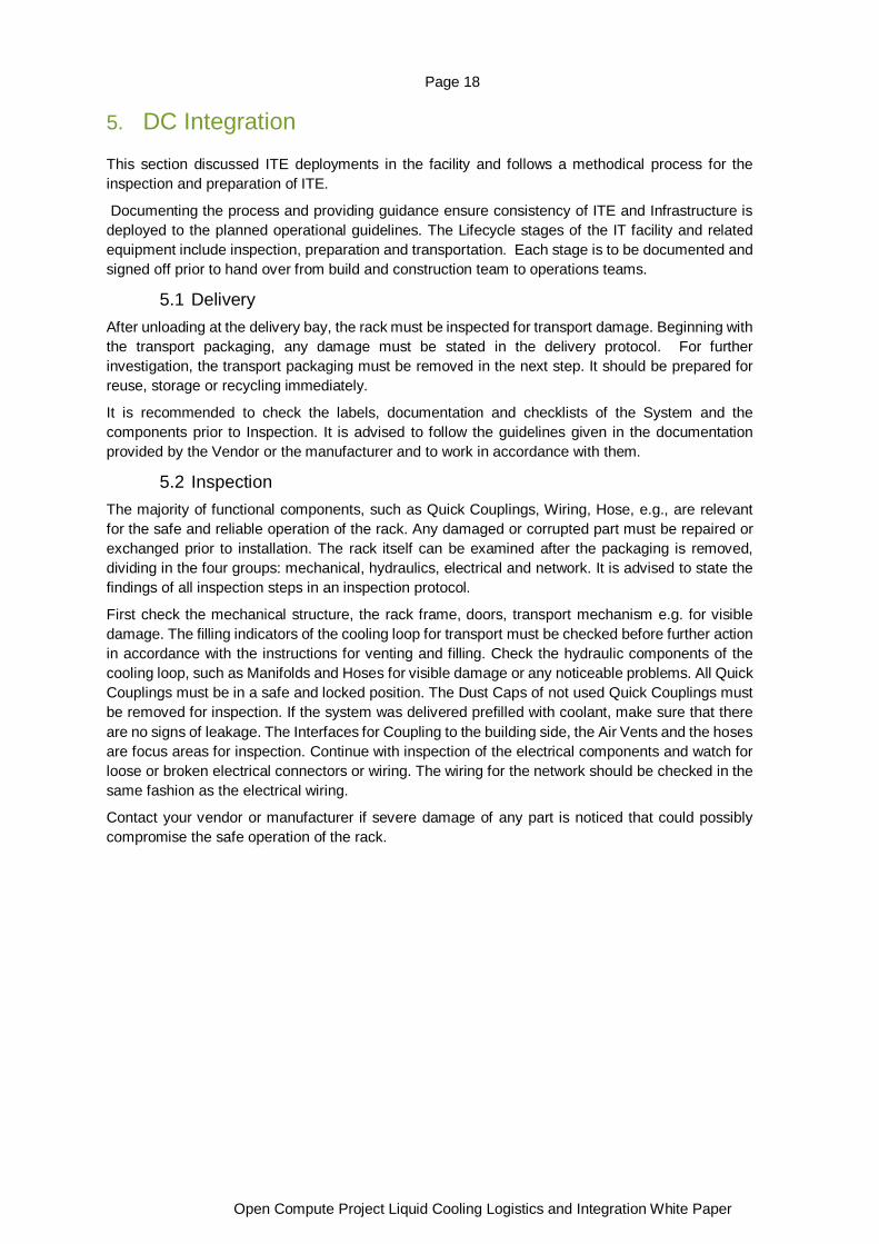
5.3 Preparation After inspection the rack is transported to an interim storage room, where it is prepared for the
integration into the data center. If no such room is available a closed section of the delivery area can be used as well. Make sure, that the room climate fits the climate conditions of the data center room in terms of temperature and humidity. The rack must acclimatize for an adequate amount of time to make sure temperature and humidity level of the components are in accordance with the storage conditions given in the documentation. If transport brackets are mounted, they should be removed and stored for later use. The rack must undergo electrical testing in accordance with country specific laws for electrical safety. The results of the tests and the standards used must be protocolled. At this stage, the cooling loop of a fully equipped rack can contain gas or
coolant (compare chapter 6). Watch for visual indicators or labels and check the documentation to make sure to proceed accordingly. If filled with gas, the cooling loop has to be drained, pressure tested and rinsed completely with the use of additional equipment like an external pump unit with a sufficient coolant reservoir (see chapter 6). It is recommended to pressure test the cooling loop with gas to detect leakage caused by the transport. For methodology of pressure testing by using gas, see chapter 6. The results of the pressure test, such as the pressure drop over time must be protocolled. For flushing of the cooling loop follow the instruction given by the manufacturer’s recommendations. As mentioned in section 5.1. Filling the cooling loop with the desired coolant, in accordance with the operation standards of the data center will be done afterwards via automated or manually operated filling pump. The pump and all connecting hoses should be flushed with fresh coolant prior to connecting to the components. It is important to make sure, that the air vents are connected and working. Otherwise, gaseous air will be trapped in the cooling loop which can lead to malfunction and outage of the liquid cooled Servers in the rack. For the filling of coolant, it must be ensured, that the complete cooling loop is connected and all Components, such as Quick Couplings and necessary valves are open to facilitate flow. To connect the filling pump, it is suggested to use the hoses connected to the manifold for the facility connection. Make sure the Quick Couplings of the filling pump correspond with the Quick Couplings on the manifold. It is recommended to fill the coolant to a pressure level near operating pressure and let the system sit in accordance with the manufacturers documentation. If an automated filling pump is used it is recommended to use the pumps to drive air out of the cooling loop continuously for a sufficient amount of time. If the pressure level does not match the required level in accordance with the documentation, the filling pump should be used to increase the pressure level to the desired point. If the rack is already filled with coolant, it is important to make sure, that the visual inspection (see above) did not show any kind of leakage. If the pressure level of the prefilled cooling loop is not in accordance with the documentation a filling pump should be used to increase the pressure level to the desired point. It is important to make sure, the air vents are connected and functional to enable the venting of gaseous air from the cooling loop. It must be assured to only use the exact type of coolant already prefilled in the system. After the filling is finished and the desired pressure point is set, all interfaces should be brought in a safe state again. The rack can now be transported to the desired location within the data center.

Page 20
Open Compute Project Liquid Cooling Logistics and Integration White Paper
6. Install, Commissioning, Operate, Decommission This section discusses how operations teams prepare the facility and the logical steps required to ensure that the installation and commissioning is done consistently and of high quality.
ITE deployments in the facility follow a methodical process for the installation and commissioning of ITE. Documenting the process and providing guidance ensure consistency of ITE and Infrastructure is deployed to the planned operational guidelines. The Lifecycle stages of the IT facility and related equipment include Planning, Installing, Commissioning, Operating and Decommissioning. Each stage is to be documented and signed off prior to hand over from build and construction team to operations teams.
6.1 Preconditions for installation All preparatory work on media routing must be completed, documented and checked, before the rack can be moved to its intended location. Specifically, this refers to the following four elements: the hydraulic system, the network, the electrical system and fire protection.
The hydraulic installation must undergo a pressure difference inspection, which should be documented in an inspection report by the same company responsible for the inspection. Furthermore, the sensors and actuators should be checked for correct fitting. Heating dummies can be connected in advance, in order to test run the cooling circuit and control technology and ensure that there are no defects in the coolant system. In this context, the focus falls on leakage detection, which only functions reliably, when leaking fluid is specifically guided to the system. To achieve this, leakage detection should be planned and functionality checked early on. To ensure safe operation, the electrical installation must be checked, logged and accepted by an authorized person and in observation of applicable standards. The installation of a functional extinguishing system at the earliest possible stage is recommended, since fires can occur as a result of error during installation works.
6.2 Installation The validation of equipment that meets design specification and includes project reference data for siting the unit and noting the serial numbers, model number, power supply details including supply voltages and wiring documentation. Additional information to capture includes software version and communication details. It is recommended to confirm unit identifiers match the installation location and the unit is correctly labelled with durable labels for ease of identification by the operations team. Visual inspection of the equipment to confirm no physical damage is evident prior to handing over to the commissioning team.
Once the preconditions have been fulfilled, the rack can be moved to its intended location. Subsequently, the rack should be checked one last time to ensure there has been no physical damage and that the rack identifiers and serial numbers correspond with the intended location. Now the media can be connected to the devices. The following sequence is recommended, to reduce potential risks. First connect and label the manifolds to the hydraulic lines according to the hydraulic plan and information. The rack should then be vented according to the manufacturer’s specifications, since air can become trapped in the hydraulic system during this process. Finally, secure all hydraulic connectors against accidental opening and confirm this work on a checklist.
Second, connect the network according to the diagrams provided. The cables must be labelled and checked off on a checklist for documentation purposes. An additional lock is not required, because the network connectors usually already have an integrated lock.
Finally, the rack can be connected to the electrical supply. Once again, all cables should be labelled according to the plan, as this makes later identification easier. Use cable ties or the security mechanisms already integrated in the connectors to secure accidental unplugging of cables.
Page 21
Open Compute Project Liquid Cooling Logistics and Integration White Paper
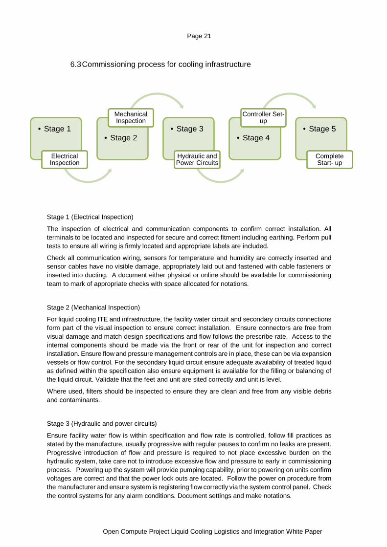
6.3 Commissioning process for cooling infrastructure
Stage 1 (Electrical Inspection)
The inspection of electrical and communication components to confirm correct installation. All terminals to be located and inspected for secure and correct fitment including earthing. Perform pull tests to ensure all wiring is firmly located and appropriate labels are included.
Check all communication wiring, sensors for temperature and humidity are correctly inserted and sensor cables have no visible damage, appropriately laid out and fastened with cable fasteners or inserted into ducting. A document either physical or online should be available for commissioning team to mark of appropriate checks with space allocated for notations.
Stage 2 (Mechanical Inspection)
For liquid cooling ITE and infrastructure, the facility water circuit and secondary circuits connections form part of the visual inspection to ensure correct installation. Ensure connectors are free from visual damage and match design specifications and flow follows the prescribe rate. Access to the internal components should be made via the front or rear of the unit for inspection and correct installation. Ensure flow and pressure management controls are in place, these can be via expansion vessels or flow control. For the secondary liquid circuit ensure adequate availability of treated liquid as defined within the specification also ensure equipment is available for the filling or balancing of the liquid circuit. Validate that the feet and unit are sited correctly and unit is level.
Where used, filters should be inspected to ensure they are clean and free from any visible debris and contaminants.
Stage 3 (Hydraulic and power circuits)
Ensure facility water flow is within specification and flow rate is controlled, follow fill practices as stated by the manufacture, usually progressive with regular pauses to confirm no leaks are present. Progressive introduction of flow and pressure is required to not place excessive burden on the hydraulic system, take care not to introduce excessive flow and pressure to early in commissioning process. Powering up the system will provide pumping capability, prior to powering on units confirm voltages are correct and that the power lock outs are located. Follow the power on procedure from the manufacturer and ensure system is registering flow correctly via the system control panel. Check the control systems for any alarm conditions. Document settings and make notations.
• Stage 1
Electrical Inspection
• Stage 2
Mechanical Inspection
• Stage 3
Hydraulic and Power Circuits
• Stage 4
Controller Set-up
• Stage 5
Complete Start- up
Page 22
Open Compute Project Liquid Cooling Logistics and Integration White Paper
Stage 4 (Controller set-up)
The necessary settings are made and checked following initial commissioning.
Confirm site requirements for settings and run through menu settings on controller to update or confirm settings. These settings include items such as user name and passwords, the alarm conditions and operating parameters for flow, pressure and temperature settings.
Follow the commissioning sheet to ensure these are included to allow for multiple unit control conditions and redundancy settings.
When starting the unit, ensure flows are lower than standard operating mode to allow system to harmonize and to vent. This will give you adequate conditions to confirm operating parameters are met, these include liquid levels, pump cycling and pressure. Once these are confirmed increase operating conditions to expected maximum performance conditions will further validate the system is operating as required
Stage 5 (Complete Start-up)
When starting the unit, ensure flows are lower than standard operating mode to allow system to harmonize. This will give you adequate conditions to confirm operating parameters are met, these include liquid levels, pump cycling and pressure. Once these are confirmed increase operating conditions to expected maximum performance conditions will further validate the system is operating as required. Follow through check lists to ensure operating conditions are met and no alarms are active.
The recording of settings and parameters can now occur, ensure these are noted for later reference by operations teams. These will include FWS and TCS fluid conditions, pump performance, temperature, flow rate and pressure conditions. A liquid sample is also required for maintenance health checks on liquid conditions in the secondary circuit. Follow through check lists to ensure operating conditions are met and no alarms are active. Then increase the system load up to - but not exceeding - the maximum operation conditions. Finally, set several prescribed fault conditions to test the function of the alarms. Once the parameters are as expected and recorded the commissioning team is ready to perform handover to operations team.
6.4 Operation Once the Site Acceptance Test has been successfully completed, and the system has been handed over to Operations, productive operation begins. There are three aspects during operation - monitoring, unscheduled maintenance and scheduled maintenance. Logs throughout the complete device life cycle are recommended, in order to track and document all incidents and maintenance steps. Sensor data and device components are checked regularly on a random basis during monitoring. Since these activities are recurrent, checklists, which build on experience with the system, should exist. Furthermore, the operations team is alerted to system errors by alarms. In the case of an alarm or a technical disruption, unscheduled maintenance may be necessary depending on the problem occurring. In contrast, scheduled maintenance activities are stipulated by the equipment manufacturer. These can be carried out as part of a service contract.
In order to simplify planning and performance of maintenance activities during operation, separate access areas are advisable. In particular, coolant monitoring, and exchange should be possible outside of the server rooms, to avoid having to move liquid containers into them.

Page 23
Open Compute Project Liquid Cooling Logistics and Integration White Paper
6.5 Decommission The devices should be operated in this manner for as long as possible, in order to both recoup investment costs as well as conserving resources with regard to environmental protection. Should the devices be decommissioned, all data and entities should first be secured or allocated to other devices. Only then should the devices be turned off, since it can never be guaranteed that an old device can be started as expected following such a halt. All documents must be gathered and assigned to the devices in advance, to ensure that passwords, logins and any device anomalies can later be understood. To this end, it is necessary to compare the device IDs with the documents and thus both keep the potential sources of error to a minimum as well as ensuring that all important information remains available for future reference.
Following this, the devices can be powered down and disconnected from the media without risk. The media should be disconnected in the opposite order for minimum risk potential, as follows: first power, then network and finally coolant. The exposed rack is then moved to an antechamber, where it can be prepared for removal.
6.6 Reuse Preparation If the hardware is still up-to-date, an overhaul must take preference over scrapping, in order to continue running the used devices in other areas of application. This represents an important contribution to environmental protection.
7. About Open Compute Project The Open Compute Project Foundation is a 501(c)(6) organization which was founded in 2011 by Facebook, Intel, and Rackspace. Our mission is to apply the benefits of open source to hardware and rapidly increase the pace of innovation in, near and around the data center and beyond. The Open Compute Project (OCP) is a collaborative community focused on redesigning hardware technology to efficiently support the growing demands on compute infrastructure. For more information about OCP, please visit us at http://www.opencompute.org
Page 24
Open Compute Project Liquid Cooling Logistics and Integration White Paper
8. References [1.] “Liquid Cooling Guidelines for Datacom Equipment Centers”, ASHRAE Datacom Series 4, 2nd
edition, 2014.
[2.] “Environmental management – Life cycle assessment – principles and framework”, 2016,
International Organization for Standardization, ISO Standard No. 14040:2006, 14044
[3.] “ACS Door Heat Exchanger Specification for Open Rack”, OCP 2021
(https://www.opencompute.org/wiki/Rack_%26_Power/Advanced_Cooling_Solutions_Door_Heat_
Exchanger)
[4.] “ACS Liquid Cooling Cold Plate Requirements”, OCP 2021,
(https://docs.google.com/document/d/1HR5O_bPcgpcjhEMGIejJ6hUor7DDx6_ek6bzvKcc7X8/edit)
[5.] UL 62368-1 IEC:2014 Audio/Video, Information and Communication Technology Equipment -
Part 1: Safety Requirements. UL. 2017.
[6] Server manufacturing levels defined, Shih, Julia, Amax 2018
(https://www.amax.com/blog/?p=668)
[7] Chen, Simon testing methodologies for liquid cooled servers, Wiwynn 2021
[8] UL safety organization, about, Wikipaedia 2021 Wiwynn 2021
(https://en.wikipedia.org/wiki/UL_(safety_organization)
[9] Open Rack v3 specification, OCP 2021
(http://files.opencompute.org/oc/public.php?service=files&t=23cadcc803bba621c720b77c60e5b95
8)
[10] Colo facility guidelines for deployment, OCP 2021
(https://www.opencompute.org/documents/dcf-colocation-facility-guidelines-for-deployment-of-
open-compute-project-racks)
[11] Forming gas, about, Wikipedia 2021 (https://en.wikipedia.org/wiki/Forming_gas)