Liquid Chillers Grasso FX GC PP - gea.com Documents/Grasso Chiller FX GC... · • High COP at full...
62
Liquid Chillers Grasso FX GC PP Product Information (Translation of the original text) L_201011_4
Transcript of Liquid Chillers Grasso FX GC PP - gea.com Documents/Grasso Chiller FX GC... · • High COP at full...

Liquid Chillers Grasso FX GC PP
Product Information (Translation of the original text)L_201011_4

COPYRIGHTAll Rights reserved.No part of this publication may be copied or pub-lished by means of printing, photocopying, microfilmor otherwise without prior written consent of
• GEA Refrigeration Germany GmbHherein after called manufacturer. This restrictionalso applies to the corresponding drawings and dia-grams.
LEGAL NOTICEThis documentation has been written in all con-science. However, the manufacturer cannot be heldresponsible, neither for any errors occurring in thisdocumentation nor for their consequences.
Product Information |Liquid Chillers Grasso FX GC PP
2 GEA Refrigeration Germany GmbH | L_201011_4 | Generated 19.01.2015

SYMBOLS USED IN THIS MANUALDanger!
Stands for an immediate danger whichleads to heavy physical injuries or tothe death.
Warning!
Stands for a possibly dangerous situa-tion which leads to heavy physicalinjuries or to the death.
Caution!
Stands for a possibly dangerous situa-tion which could lead to light physicalinjuries or to damages to property.
Hint!
Stands for an important tip whoseattention is important for the designa-ted use and function of the device.
Product Information |Liquid Chillers Grasso FX GC PP
GEA Refrigeration Germany GmbH | L_201011_4 | Generated 19.01.2015 3

Product Information |Liquid Chillers Grasso FX GC PP
4 GEA Refrigeration Germany GmbH | L_201011_4 | Generated 19.01.2015

TABLE OF CONTENTS1 MAIN MODULES 9
1.1 General description 91.1.1 Operating areas and advantages of FX GC PP 91.1.2 Technical description FX GC 91.1.3 Chiller with reciprocating compressors - series FX GC and MX GC 101.1.4 Description of main components 13
1.1.4.1 Reciprocating compressor 131.1.4.2 Compressor drive motor 131.1.4.3 Evaporator + liquid separator 141.1.4.4 Condenser 151.1.4.5 Injection control 161.1.4.6 Oil return system 161.1.4.7 Fittings 161.1.4.8 Switching cabinet / control 17
2 MAIN DATA 192.1 Technical Data 19
2.1.1 Grasso FX GC PP 260 NH3 to Grasso FX GC PP 1250 NH3 192.1.2 Grasso FX GC PP 520 NH3 to Grasso FX GC PP 900 NH3 212.1.3 Grasso FX GC PP 1050 duo NH3 to Grasso FX GC PP 1800 duo NH3 232.1.4 Operation limits 242.1.5 Acoustic values 25
2.2 P+I diagrams 262.2.1 P+I diagram FX GC PP 262.2.2 Designation for main components and fixtures - Liquid chiller Grasso FX GC PP NH3 272.2.3 P+I diagram FX GC PP duo 292.2.4 Designation for main components and fixtures - Liquid chiller Grasso FX GC PP NH3 30
2.3 Main dimensions 322.3.1 FX GC PP 260 to FX GC PP 1250 322.3.2 FX GC PP 520 duo to FX GC PP 1800 duo 34
2.4 Capacity calculation 362.5 Pressure losses 36
3 INSTALLATION 373.1 Installation 37
3.1.1 Delivery 373.1.2 Basic information for installation 37
3.1.2.1 Information regarding installation in machinery room 373.1.2.2 Rigid installation 373.1.2.3 Installation of the Screw Compressor for Insulation against Structure-borne
Sound 373.1.2.4 Electrical connection 383.1.2.5 Sound insulation, weather protection 383.1.2.6 Air-cooled condenser and evaporation condenser for GG LP and GC VP ser-
ies 383.1.3 Secondary refrigerant system 383.1.4 Heating agent system 383.1.5 Water pipes 393.1.6 Refrigerant lines 393.1.7 Electrical installation 393.1.8 Installation information 40
3.1.8.1 Foundation plan 403.2 SECONDARY REFRIGERANT SYSTEMS ON RECIPROCATING CHILLERS 41
3.2.1 Single chiller, single pump systems 413.2.2 Single chiller, double-pump systems 433.2.3 Multi chiller, double-pump systems 44
3.3 Transport (crane transport) 464 MAINTENANCE INSTRUCTIONS 49
4.1 Maintenance schedule for liquid chiller 494.2 Regular maintenance 494.3 Machine room information 49
Product Information |Liquid Chillers Grasso FX GC PP
GEA Refrigeration Germany GmbH | L_201011_4 | Generated 19.01.2015 5

4.4 Personal protection 495 SPECIFICATION 50
5.1 FX GC PP NH3 505.1.1 Technical Data 505.1.2 Package 515.1.3 Not included in scope of delivery 54
5.2 FX GC PP duo NH3 555.2.1 Technical Data 555.2.2 Package 575.2.3 Not included in scope of delivery 60
Product Information |Liquid Chillers Grasso FX GC PP
6 GEA Refrigeration Germany GmbH | L_201011_4 | Generated 19.01.2015

TABLE OF FIGURESfig. 1 Position of the reciprocating compressor 13fig. 2 Position of the compressor drive motors 13fig. 3 Arrangement of the evaporator 14fig. 4 Position of the liquid separator 14fig. 5 Position of the condenser 15fig. 6 Heat recovery 15fig. 7 Injection control 16fig. 8 Position of the oil return 16fig. 9 Position of the switching cabinet 17fig. 10 P+I diagram FX GC PP 26fig. 11 P+I diagram FX GC PP duo 29fig. 12 Set drawing FX GC PP 32fig. 13 Set drawing FX GC PP duo 34fig. 14 Foundation plan 40fig. 15 Single chiller, single pump systems 41fig. 16 Compressor switching frequency 42fig. 17 Single chiller, double-pump systems 43fig. 18 Multi chiller, double-pump systems 44fig. 19 Designation of the lifting points 46fig. 20 Transport 47fig. 21 Shackles 47
Product Information |Liquid Chillers Grasso FX GC PP
GEA Refrigeration Germany GmbH | L_201011_4 | Generated 19.01.2015 7

Product Information |Liquid Chillers Grasso FX GC PP
8 GEA Refrigeration Germany GmbH | L_201011_4 | Generated 19.01.2015

1 MAIN MODULES
1.1 General description
1.1.1 Operating areas and advantagesof FX GC PP
The FX GC PP series of liquid chillers was devel-oped as an alternative to the R22 liquid chillers. Thefunction and construction principles enable theirdeployment in many cases formally reserved for theR22 refrigerant, e.g.:
• Cold water supply for air conditioners
• Process cooling
• Heat pumps
• Refrigeration over a range of normal tempera-tures using secondary refrigerant temperaturesdown to -10°C.
Ammonia (R717) has the following advantages overrefrigerant R134a:
• It is a natural substance (in the nitrogen cycle)
• Low TEWI (Total Equivalent Warming Impact),i.e. the direct greenhouse effect of the refrigerantand the indirect effect of the energy consumptionby the unit, making it very environmentally com-patible.
• Its GWP (Global Warming Potential) is zero.
• Its ODP (Ozone Depletion Potential) is zero.
• It has a low odour threshold which serves as aneffective warning in the event of leaks.
• It has served as a refrigerant for decades andhas caused no long-term damage.
• It provides a greater refrigerating capacity for thesame investment expenditure.
• It has a better coefficient of performance
Hint!
The installation must comply with therelevant directives for ammonia refrig-eration systems in Germany, e.g. UVVBGV D4 (formerly VBG 20), DIN 8975and EN 378.
The FX GC range gives safe and dependable opera-tion with the following features:
• Module-welded plate evaporators
• Module-welded plate condensers
• Cylindrical heat exchangers which are easy toinsulate
• All refrigerant-carrying lines are safely mounted
• Automatic oil return system for globally availablemineral oil.
• Bypass line from the pressure line to the suctionline with bypass line for the compressor.
• Stored-program control and monitoring.
• High COP at full load and part load conditions
• Improved partial load output index
1.1.2 Technical description FX GC
FX GC are chillers for interior operation in machinerooms or similar housings for outdoor installationwhich are assembled and tested in the manufactur-er's facilities.The chillers are automatically-operating single stagechiller units with reciprocating compressors and floo-ded plate evaporators for cooling water or brine asthe secondary refrigerant.The complete FX GC range comprises 3 series,which can be supplied or complemented with differ-ent condensers:
GC PP Liquid chiller with water-cooled con-denser and closed refrigerant circuit
GC LP Evaporator set for connection to a singleair cooled condenser.
GC VP Evaporator set for connection to a singleair cooled evaporative condenser.
Using the Grasso reciprocating compressor theFXGC range covers a cooling capacity of 260 to1800 kW for cold water products.Capacity is automatically adjusted by internal controlfacilities which shut down compressors/cylindersincrementally to suit refrigerating loads. The chillerscan be transported assembled.The chillers are produced in accordance with thevalid German regulations (DIN, UVV, VDE) or inaccordance with the regulations of the destinationcountry and have a CE certification.
Product Information |Liquid Chillers Grasso FX GC PP
MAIN MODULES
GEA Refrigeration Germany GmbH | L_201011_4 | Generated 19.01.2015 9

1.1.3 Chiller with reciprocating compressors - series FX GC and MX GC
X Chiller series
Y Condenser version
Z Evaporator version
9Nominal chiller capacity in kWpertaining to cold-water operations 12°C / 6°C
X1 Chiller type
X2 Refrigerant
X Chiller type
FX GC flooded evaporation
MX GC Special design (flooded evaporation)
Y Condenser version
P Plate heat exchanger (cassette welding)
S Shell and plate condenser (completely welded)
R Tube bundle condenser
MAIN MODULES Product Information |Liquid Chillers Grasso FX GC PP
10 GEA Refrigeration Germany GmbH | L_201011_4 | Generated 19.01.2015

L Air cooled condenser (not in the scope of delivery for GEA Refrigeration Germany)
V Vapour condenser (not in the scope of deliver for GEA Refrigeration Germany)
Z Evaporator version
P Plate heat exchanger (cassette welding)
S Plate heat exchanger (completely welded)
O without evaporator (condensing unit)
9 Nominal chiller capacity at 1500 min-1 (V300 ... V600) / 1200 min-1 / (V700 ... V1800) in kW related to coldwater operation 12 °C / 6 °C
with 1 compressors
Compressor type Nominal capacity in kW
V300 260
V450 400
V600 525
V700 600
V1100 900
V1400 1250
V1800 1500
Design with 2 compressors
Compressor type Nominal capacity in kW
2x V300 520
V300 / V450 650
2x V450 800
V450 / V600 900
2x V600 1050
2x V700 1200
Product Information |Liquid Chillers Grasso FX GC PP
MAIN MODULES
GEA Refrigeration Germany GmbH | L_201011_4 | Generated 19.01.2015 11

Design with 2 compressors
Compressor type Nominal capacity in kW
V700 / V1100 1500
2x V1100 1800
V1100 / V1400 2200
2x V1400 2500
V1400 / V1800 2750
2x V1800 3000
X1 design of the chiller
(without) Standard version with 1 reciprocating compressor
duo Standard version with 2 reciprocating compressor
X2 refrigerant
NH3 Ammonia
Naming example
FX GC PP 900duo NH3
Chiller with reciprocating compressor (FX GC)with plate heat exchanger as condenser (P),with plate heat exchanger as evaporator (P),Nominal capacity 900 kW (900),2 Compressor (duo),for refrigerant ammonia (NH3)
MAIN MODULES Product Information |Liquid Chillers Grasso FX GC PP
12 GEA Refrigeration Germany GmbH | L_201011_4 | Generated 19.01.2015

1.1.4 Description of main components
1.1.4.1 Reciprocating compressor
fig.1: Position of the reciprocating compressor
The FX GC PP chillers use open, single-action,multi-cylinder reciprocating compressors for therefrigerant ammonia (R717) in the rated capacityrange of 291 to 1274 m3/h per compressor.The ammonia vapours created in the evaporator areexhausted and compressed to condensation pres-sure in one or several compressors.The pressure and temperature transmitters installedon the compressor are used to monitor the operatingvalues of each compressor. With compressors theindividual cylinders can be switched off either bybypass valves or suction valve relief devices.The compressors have the following equipment fea-tures:
– Start-up load relief
– Capacity control by cylinder switch-off
– Oil differential pressure control
– Oil heater
– Discharge pressure monitoring
– Suction pressure monitoring
– Crankcase pressure monitoring
– Discharge temperature control
– Oil temperature monitoring
– Suction temperature monitoringSafety equipment on the pressure generators isstandard in compliance with EN 378 and accidentprevention regulations BGV D4 by current linkagevalves combined with DBK safety pressure limiters.
To prevent overheating, the compressed gas tem-perature is monitored for each compressor.
1.1.4.2 Compressor drive motor
fig.2: Position of the compressor drive motors
The compressors are driven via a coupling by meansof a 4-pole or 6-pole IP23 (option IP55) electricmotor with an operating voltage of 400V; 50 Hz runwith a clutch.Optionally, motors can be used in FC operation.
Product Information |Liquid Chillers Grasso FX GC PP
MAIN MODULES
GEA Refrigeration Germany GmbH | L_201011_4 | Generated 19.01.2015 13

1.1.4.3 Evaporator + liquid separator
fig.3: Arrangement of the evaporator
In the evaporator heat is absorbed from the coolingwater or brine (which is thereby cooled) by way ofevaporation and superheating of the refrigerant. Theevaporator works on the principle of flooded evapo-ration with external circulation.The module-welded heat exchanger plates, madefrom AISI 304 stainless steel (other materials onrequest), are clamped together between the standplate and the pressure plate using pulling bolts andattached to the upper carrying rod and the lowerguide rail. The individual plate modules are sealedon the coolant side with ring gaskets and on thecoolant/heating agent side with (adhesive-free) elas-tomer field gaskets.
fig.4: Position of the liquid separator
Liquid drops are effectively separated in the liquidseparator located above the evaporator.In the operating state, the evaporator is flooded withammonia up to the height of the upper sight glass inthe circulation line (item 2555.2).
Non-soluble heavier oil is deposited in the oil domeand returns automatically controlled from there to thecompressor or compressors. For further details, seeOil return system section.In the case of external condensing systems, a maxi-mum level indicator is installed in the liquid separatorto provide additional protection against overfilling.The suction pressure and secondary refrigerant out-let temperature are monitored to provide reliable pro-tection against freezing.The liquid separator and suction line are suppliedwith water vapour diffusion-proof insulation.The evaporator can be optionally provided with adetachable insulation box.Design, manufacture and acceptance comply withthe requirements of the pressure appliances direc-tive.There is no evaporator when the chiller is designedas a condensing unit.
MAIN MODULES Product Information |Liquid Chillers Grasso FX GC PP
14 GEA Refrigeration Germany GmbH | L_201011_4 | Generated 19.01.2015

1.1.4.4 Condenser
fig.5: Position of the condenser
In the condenser the compressed refrigerant vapouris heated, liquefied and supercooled by dissipatingthe energy absorbed in the evaporator and compres-sor to the heating agent (heating).The module-welded heat exchanger plates, madefrom AISI 316 stainless steel (other materials onrequest), are clamped together between the standplate and the pressure plate using pulling bolts andattached to the upper carrying rod and the lowerguiding rod.If the chillers are designed as evaporator units, thewater-cooled condenser is not installed. In this case,the refrigerant circuit is completed by the customerwith other condenser types.The heating agent inlet is connected at the bottom,the outlet connector is located at the top.Heat recovery (optional)Depending on the temperature level of the mediumto be heated, the overheated vapour provided by thecompressor or compressors can either be cooled,cooled and partly condensed, or fully condensed. Inorder to achieve the maximum heat exchange sur-face in the condenser, the condensed ammoniaarriving from the desuperheater (item 2900) shouldbe discharged. From the specific separator/leveltank, the liquid-free vapour can flow to the condenserwhere it is liquefied.
fig.6: Heat recovery
1 Customer-sided
Product Information |Liquid Chillers Grasso FX GC PP
MAIN MODULES
GEA Refrigeration Germany GmbH | L_201011_4 | Generated 19.01.2015 15

1.1.4.5 Injection control
In GC PP series units, the pressure drop of the liquidrefrigerant from condensation pressure to evapora-tion pressure and the optimal utilization of the evapo-rator capacity are ensured by the ECD (electroniccondenser drain) system. The action of the ECD sys-tem is based on the variables suction pressure, endpressure, NH3- level measurement, output powerand the speed of the compressors.In the case of FX PP, the NH3level measurement(LC, item 2240.1/2) is made on the high pressureside. The condensate flows at low speed (< 0.3 m/s)into the level tank. Injection valve AKVA (Item 2510)functions according to the pulse to no-current princi-ple. The cycle time is 3 seconds, i.e. after an open-ing time of 3s, it is 100% open. The ECD softwarewill continuously calculate the percentage of openingrequired for the injection valve.
fig.7: Injection control
1. From the condenser
2. Sight glass
3. High-pressure liquid container
4. Level sensor high
5. Level sensor low
6. To the evaporator
In evaporator chillers, level measuring is arranged onthe low pressure side and it is provided with an addi-tional solenoid valve and liquid filter upstream of theinjection valve.
1.1.4.6 Oil return system
fig.8: Position of the oil return
The reciprocating compressor requires special refrig-erating machine oil for lubrication and control.A small part of the oil is carried off in the circuit dur-ing the compressing process.This is returned from the evaporator to the compres-sor by an automatic, maintenance-free oil return sys-tem (developed by GEA Refrigeration GermanyGmbH) on the low pressure side of the chiller.
1.1.4.7 Fittings
The term 'fittings' generally designates a control ele-ment of the machine. Among other things, the term'fittings' is also used for valves if they are used forthe control and regulation of fluid flows in the pipes.Furthermore, all kinds of installations in pipes, suchas sight glasses, measurement apertures, filters andsimilar, are also designated as fittings. Therefore, fit-tings also include all kinds of valves, such as
– Stop valves
– Check valves
– Safety valves
– Throttle valvesEach fitting has its own field of use, according to thepressure or temperature in the pipe, the size of thepipe, the sealing requirements for the fitting, thereduction and direction of the flow of liquid, as wellas the medium itself.The safety fittings are used to limit the pressure insystems which are under pressure.
MAIN MODULES Product Information |Liquid Chillers Grasso FX GC PP
16 GEA Refrigeration Germany GmbH | L_201011_4 | Generated 19.01.2015

Each fitting is designed for the specific application.The fittings can be operated manually or by motor,e.g. by gear motors, or pneumatic or hydraulic cylin-ders. In reset fittings, the flow of fluid in the pipe cau-ses automatic closing of the valve.Depending on the model, different closing elements(e.g. valve discs, flaps, washers) close the pipe con-nected to the fitting.For service and maintenance tasks, manual stopvalves are installed:
– in the compressed gas line between the com-pressor and condenser,
– in the injection line between the injection valveand evaporator,
– before the liquid filter for evaporator units in theliquid line
– in the suction line between evaporator and com-pressor
A suction filter in the compressor protects it from dirt.The filter cartridge can be cleaned or replaced.
Hint!
The documentation of the fittings(acceptance certificates) forms part ofthe product documentation.
1.1.4.8 Switching cabinet / control
fig.9: Position of the switching cabinet
The chillers are supplied with a switching cabinet asstandard.For transporting the chiller, the switching cabinet ismounted on beams. These must be removed duringinstallation on site and the switching cabinet placedon a level surface.Instructions for setting down the switching cabinet onthe on-site foundation can be found in the order-spe-cific drawing of the chiller.The switching cabinet is configured according to thetechnical specifications indicated in each order.The chillers have a type GSC TP control asstandard.
Hint!
All instructions for the controls referto the GSC TP (hereinafter referred toas the GSC).
The GSC consists of the control unit with operatorkeypad and display unit, indicator lights for "Run-ning", "Warning" and "Alarm", the emergency stopbutton, the output relays and the casing.
Hint!
It is not permitted to add an externalcontroller between the GSC and thepower panel; this would extend thesafety chain to be achieved. All controlsignals between the GSC and thepower panel must be processeddirectly and must not flow indirectlyvia an external controller. The manu-facturer cannot otherwise guaranteethe safe operation of the system.
Product Information |Liquid Chillers Grasso FX GC PP
MAIN MODULES
GEA Refrigeration Germany GmbH | L_201011_4 | Generated 19.01.2015 17

The GSC performs the following functions asstandard:
• Display of all important physical and technicalparameters, e.g.
– Pressure
– Temperature
– Capacity
– Number of operating hours
– Operation mode
– Status reports
• Automatic startup and shutdown of the chillerand capacity control dependent on the followingvalues:
– Suction pressure
– Inlet temperature
– Outlet temperature
– External temperature
• Monitoring of all operating parameters
• Motor current monitoring
• Compressor power limitation if the measured dis-charge pressure, discharge temperature, motorcurrent or suction pressure indicate an overload
• Fault memory with date and time
• Wire failure detection for analogue input signals
• Password protection for preventing unauthorisedaccess to important parameters
• Control of the chiller by a master controller viapotential-free contacts
• Possibility of communication via MPI or ModbusRTU/TCP with master controller or building man-agement system
• 10-minute trend display with display of all actualvalues which existed just before alarm shutoff
• Remote maintenance via Ethernet connection(TCP/IP)
The GSC optionally performs the following func-tions:
– Frequency-controlled compressor drive motor
– Electronic flow switch for secondary refrigerantcircuit
– Electronic flow switch for heating agent circuit
– Remote setpoint adjustment (analogue signal)
– Profibus DP communication
The documentation for the GSC is part of the productdocumentation.
MAIN MODULES Product Information |Liquid Chillers Grasso FX GC PP
18 GEA Refrigeration Germany GmbH | L_201011_4 | Generated 19.01.2015

2 MAIN DATA
2.1 Technical Data
2.1.1 Grasso FX GC PP 260 NH3 to Grasso FX GC PP 1250 NH3
Type sizes FX GC PP 260 400 525 600 900 1250
Refrigerating capacity 1) Q0 kW 277 415 554 638 957 1276
Power consumption
Compressor 1) PeffkW 48.1 71.2 94.3 103.4 153.3 203.6
Weight without charging mL kg 4100 4600 5750 6300 8250 11500
Operating weight mB kg 4250 4750 6000 6550 8600 11900
Refrigerant charging quantity NH3 kg 38 42 48 61 83 135
Oil charging quantity VOIL l 11.5 13.5 18.5 21.5 28.5 41.5
Secondary refrigerant volume l 27 40 54 62 91 136
Heating agent volume l 28 40 71 83 132 150
Secondary refrigerant connections 2) DN 100 100 100 100 100 150
Heating agent connections 2) DN 100 100 150 150 150 250
Grasso compressor Type V300 V450 V600 V700 V1100 V1400
LS power levels
%25/50/75
10033/50/6783/100
25/37/5062/75/8775/87/10
0
25/50/75100
33/50/6783/100
25/37/5062/75/87
100
Electrical data of compressor motor -1500 min –-1, 400 V / 3 Ph / 50 Hz3), IP 23, air cooled
Nominal capacity 4) Pn kW 55 90 110 132 200 250
Rated current at 400 V In A 97.5 159 195 251 371 466
Relative start-up current 5) Ia/In 6.5 6.5 7.5 6.8 6.8 6
Switching cabinet for power supply 3 PEN / 400 V, internal control voltage: 230 V / 50 Hz / 24 VDC
Product Information |Liquid Chillers Grasso FX GC PP
MAIN DATA
GEA Refrigeration Germany GmbH | L_201011_4 | Generated 19.01.2015 19

Type sizes FX GC PP 260 400 525 600 900 1250
Supply line cross-section mm2 70 120 185 185 2x120 2x150
Primary fuse A 160 250 315 315 400 500
t K1/K2= 12 / 6 °C; t W1/W2 = 27 / 32 °C2) Connection flange for cooling and heating agent based on DIN 2633 (corresponds to ISO PN 16)3) Euro voltage area ±10%, other voltages / frequencies upon demand4) For water inlet/outlet 12/6°C; if conditions vary, motor output differs5) For Y - Δ start-up, the starting values are reduced to 30 %
Hint!
Variation in secondary refrigerant and heating agent temperatures can lead to changes in theheat exchanger and motor classification and therefore to different technical data.
MAIN DATA Product Information |Liquid Chillers Grasso FX GC PP
20 GEA Refrigeration Germany GmbH | L_201011_4 | Generated 19.01.2015

2.1.2 Grasso FX GC PP 520 NH3 to Grasso FX GC PP 900 NH3
Size FX GC PP duo 520 650 800 900
Refrigerating capacity 1) Q0 kW 554 690 830 969
Power consumption
Compressor 1) PeffkW 96.2 119.3 142.4 165.5
Weight without charging mL kg 5450 7200 8150 9100
Operating weight mB kg 5600 7450 8350 9400
Refrigerant charging quantity NH3 kg 53 73 90 106
Oil charging quantity VOIL l 23 25 27 32
Secondary refrigerant volume l 54 60 70 91
Heating agent volume l 58 65 65 132
Secondary refrigerant connections 2) DN 100 100 100 100
Heating agent connections 2) DN 100 100 100 150
Grasso compressor Type V330+V300 V450+V300 V450+V450 V600+V450
LS power levels% 25/38/50 /
63/75/ 87/10020/30/40 /
50/60 / 80/100
16/25/33 /42/50/66 /
75/83/92 /100
14/28/43 /50/57/71 /
78/86/ 92/100
Electrical data of compressor motor -1500 min –-1, 400 V / 3 Ph / 50 Hz3), IP 23, air cooled
Nominal capacity 4) Pn kW 55+55 90+55 90+90 110+90
Rated current at 400 V In A 97.5+97.5 159+97.5 159+159 195+159
Relative start-up current 5) Ia/In 6.5/6.5 6.5/6.5 6.5/6.5 7.5/6.5
Switching cabinet for power supply 3 PEN / 400 V, internal control voltage: 230 V / 50 Hz / 24 VDC
Supply line cross-section mm2 120 185 2x120 2x120
Primary fuse A 250 315 400 400
t K1/K2= 12 / 6 °C; t W1/W2 = 27 / 32 °C2) Connection flange for cooling and heating agent based on DIN 2633 (corresponds to ISO PN 16)
Product Information |Liquid Chillers Grasso FX GC PP
MAIN DATA
GEA Refrigeration Germany GmbH | L_201011_4 | Generated 19.01.2015 21

3) Euro voltage area ±10%, other voltages / frequencies upon demand4) For water inlet/outlet 12/6°C; if conditions vary, motor output differs5) For Y - Δ start-up, the starting values are reduced to 30 %
Hint!
Variation in secondary refrigerant and heating agent temperatures can lead to changes in theheat exchanger and motor classification and therefore to different technical data.
MAIN DATA Product Information |Liquid Chillers Grasso FX GC PP
22 GEA Refrigeration Germany GmbH | L_201011_4 | Generated 19.01.2015

2.1.3 Grasso FX GC PP 1050 duo NH3 to Grasso FX GC PP 1800 duo NH3
Size FX GC PP duo 1050 1200 1500 1800
Refrigerating capacity 1) Q0 kW 1108 1276 1595 1914
Power consumption
Compressor 1) PeffkW 188.6 206.8 256.7 407.2
Weight without charging mL kg 9500 12500 13600 14900
Operating weight mB kg 10000 13000 14100 15500
Refrigerant charging quantity NH3 kg 115 175 222 240
Oil charging quantity VOIL l 37 43 50 57
Secondary refrigerant volume l 105 136 178 234
Heating agent volume l 157 149 190 230
Secondary refrigerant connections 2) DN 100 150 150 150
Heating agent connections 2) DN 150 250 250 250
Grasso compressor Type V600+V600 V700+V700 V1100+V700 V1100+V1100
LS power levels
%
18/25/43 /50/56/
68/75/81 /93/100
25/38/50 /63/75/ 87/100
20/30/40 /50/60 / 80/100
16/25/33 /42/50/66 /
75/83/92 /100
Electrical data of compressor motor -1500 min –-1, 400 V / 3 Ph / 50 Hz3), IP 23, air cooled
Nominal capacity 4) Pn kW 110+110 132+132 200+132 200+200
Rated current at 400 V In A 195+195 251+251 371+251 371+371
Relative start-up current 5) Ia/In 7.5/7.5 6.8/6.8 6.8/6.8 6.8/6.8
Switching cabinet for power supply 3 PEN / 400 V, internal control voltage: 230 V / 50 Hz / 24 VDC
Supply line cross-section mm2 2x150 3x120 3x150 3x185
Primary fuse A 500 630 800 800
t K1/K2 = 12 / 6 °C; t W1/W2 = 27 / 32 °C
Product Information |Liquid Chillers Grasso FX GC PP
MAIN DATA
GEA Refrigeration Germany GmbH | L_201011_4 | Generated 19.01.2015 23

2) Connection flange for cooling and heating agent based on DIN 2633 (corresponds to ISO PN 16)3) Euro voltage area ±10%, other voltages / frequencies upon demand4) For water inlet/outlet 12/6°C; if conditions vary, motor output differs5) For Y - Δ start-up, the starting values are reduced to 30 %
Hint!
Variation in secondary refrigerant and heating agent temperatures can lead to changes in theheat exchanger and motor classification and therefore to different technical data.
2.1.4 Operation limits
The ammonia chillers (flooded evaporation) can beoperated under the most varied operation conditionswithin the given limits of application according to therequirements involved. The limits of application listedbelow are based on the operational principle of thereciprocating compressor, thermodynamic relations,used vessels and safety devices and practical oper-ating conditions. The appropriate Compressor modeldesign should be selected for the particular operatingconditions.
Caution!
When considering a specific applica-tion, all the conditions specified in thetable must be taken into account andadhered to.
Suction pres-sure
p0 bar (a)minmax
0.77.0
Outlet tempera-ture of water assecondaryrefrigerant
tKA °Cminmax
+3+15
Outlet tempera-ture with frost-resistant secon-dary refriger-ants
tKA °Cminmax
-10+15
Condensingpressure
pc bar (a)minmax
1023
Inlet tempera-ture of heatingagent
tWE °Cminmax
+20+45
The specified operation limits apply to operation atfull load.
Partial load operation can lead to limitation of theoperation limits and must be checked in the specificapplication.
Caution!
During operation of the chiller, theincrease of the secondary refrigerantinlet temperature must be limited tomax. 3 K within 2 minutes.
If the specified limits are exceeded for a specificapplication, the manufacturer must be consulted.In addition to the operating limits stated in the tables,the operating conditions of the respective compres-sor type to be complied with must also be taken intoaccount (e.g. start-up regime, oil pressure, quantityof oil, type of oil, etc.).The data entered pertain to the operating conditionsfor a chiller or air conditioner. During shut-down orduring start-up, the limits may temporarily be excee-ded or not be met (never permanently).
MAIN DATA Product Information |Liquid Chillers Grasso FX GC PP
24 GEA Refrigeration Germany GmbH | L_201011_4 | Generated 19.01.2015

2.1.5 Acoustic values
Size GCP
Totalsoundpres-sure1)LP[dB(A)]
Soundpower
LWA[dB(A)]
Octave sound pressureLPOct [dB]
Average sound frequency fm [Hz]
63 125 250 500 1000 2000 4000 8000
260 75 90 81 89 92 90 87 85 83 77
400 78 92 91 89 85 92 91 87 85 79
525 80 96 83 95 94 97 93 84 83 82
600 83 101 87 98 101 97 98 93 88 86
900 83 101 88 99 101 99 98 94 88 86
1250 83 101 88 99 101 99 98 94 88 86
Size GC P duo
520 79 93 84 92 95 93 90 88 86 80
650 81 94 84 92 93 94 92 89 87 81
800 81 95 84 92 88 95 94 90 88 82
900 84 97 85 96 95 98 95 89 87 84
1050 86 99 86 98 97 100 96 87 86 85
1200 87 103 90 100 102 100 101 95 100 88
1500 88 104 90 101 104 100 101 96 91 89
1800 88 104 91 102 104 101 101 97 91 89
1) Measuring point distance 1m; coolant and heating pump range tolerances up to +3 dB
Product Information |Liquid Chillers Grasso FX GC PP
MAIN DATA
GEA Refrigeration Germany GmbH | L_201011_4 | Generated 19.01.2015 25

2.2 P+I diagrams
2.2.1 P+I diagram FX GC PP
fig.10: P+I diagram FX GC PP
1 Customer
2 GEA Refrigeration Germany GmbH
3 Temperature probe, delivered separately
4 Flow controller, delivered separately
5 Temperature probe, delivered separately/ for installation in line 2 m after evaporator
6 Secondary refrigerant
7 Heating agents
8 Connection made on the liquid separator
MAIN DATA Product Information |Liquid Chillers Grasso FX GC PP
26 GEA Refrigeration Germany GmbH | L_201011_4 | Generated 19.01.2015

2.2.2 Designation for main compo-nents and fixtures - Liquid chillerGrasso FX GC PP NH3
Item Name
10 Reciprocating compressor
15 Motor
16 Motor current converter
17 Motor winding protection
45 Suction filter, compressor
50 Solenoid valve capacity control, compres-sor
90 Service valve, compressor
95 Coupling between motor/compressor
100 Pressure transmitter, suction pressure
101 Pressure transmitter, crankcase pressure
105 Pressure transmitter, discharge pressure
110 Pressure transmitter, oil pressure
115Resistance thermometer Pt1000Suction temperature
120Resistance thermometer Pt1000Discharge temperature
125Resistance thermometer Pt1000Oil temperature
260 Pressure stop valve
280 Suction stop valve
340 Overflow valve, compressor
350 Safety pressure limiter
Item Name
360 Oil heater, compressor
2000 Evaporator
2040 Resistance thermometer, secondaryrefrigerant outlet
2045 Resistance thermometer, secondaryrefrigerant inlet
2050 Flow switch
2060 Filling and drain valve
2100 Condenser
2200 Liquid separator
2205 Service valve
2230 Safety valve combination
2235 Stop valve, injection
2255 Service valve
2280 Heating element
2300 Pulse pump for oil return
2305 GPV32D valve
2310 Solenoid valve, oil return
2315 Stop valve
2320 Stop valve, oil return
2325 Sight glass
2330 Service valve
2340 Nonreturn valve, oil return
2345 Dirt filter, oil return
2350 Stop valve
Product Information |Liquid Chillers Grasso FX GC PP
MAIN DATA
GEA Refrigeration Germany GmbH | L_201011_4 | Generated 19.01.2015 27

Item Name
2360 Oil heater, pulse pump
2370 Resistance thermometer, pulse pump
2410 Stop valve, overflow valve
2415 Stop valve, overflow valve
2420 Overflow valve
2555 D28 sight glass
MAIN DATA Product Information |Liquid Chillers Grasso FX GC PP
28 GEA Refrigeration Germany GmbH | L_201011_4 | Generated 19.01.2015

2.2.3 P+I diagram FX GC PP duo
fig.11: P+I diagram FX GC PP duo
1 Customer
2 GEA Refrigeration Germany GmbH
3 Temperature probe, delivered separately
4 Flow controller, delivered separately
5 Temperature probe, delivered separately/for installation in line 2 m after evaporator
6 Secondary refrigerant
7 Heating agents
8 Connection made on the liquid separator
Product Information |Liquid Chillers Grasso FX GC PP
MAIN DATA
GEA Refrigeration Germany GmbH | L_201011_4 | Generated 19.01.2015 29

2.2.4 Designation for main compo-nents and fixtures - Liquid chillerGrasso FX GC PP NH3
Item Name
10 Reciprocating compressor 1
15 Motor 1
16 Motor current converter 1/2
17 Motor winding protection 1/2
20 Reciprocating compressor 2
25 Motor 2
45 Suction filter, compressor 1/2
50solenoid valve capacity controlCompressor 1/2
90 Service valve, compressor 1/2
95 Coupling between motor/compressor 1/2
100 Pressure transmitter, suction pressure1/2
101 Pressure transmitter, crankcase pres-sure 1/2
105 Pressure transmitter, discharge pres-sure 1/2
110 Pressure transmitter, oil pressure 1/2
115Resistance thermometer Pt1000Suction temperature 1/2
120Resistance thermometer Pt1000Discharge temperature 1/2
125Resistance thermometer Pt1000Oil temperature 1/2
250 Pressure stop valve Compressor 1
Item Name
255 Pressure stop valve Compressor 2
288 Suction stop valve Compressor 1
285 Suction stop valve Compressor 2
340 Overflow valve, compressor 1/2
350 Safety pressure limiter 1/2
360 Oil heater, compressor 1/2
2000 Evaporator
2040 Resistance thermometer, secondaryrefrigerant outlet
2045 Resistance thermometer, secondaryrefrigerant inlet
2050 Flow switch
2060 Filling and drain valve
2100 Condenser
2200 Liquid separator
2205 Service valve
2230 Safety valve - combination
2235 Stop valve, injection
2255 Service valve
2280 Heating element
2300 Pulse pump for oil return
2305 GPV32D valve
2310 Solenoid valve, oil return
2315 Stop valve
2320 Stop valve, oil return
MAIN DATA Product Information |Liquid Chillers Grasso FX GC PP
30 GEA Refrigeration Germany GmbH | L_201011_4 | Generated 19.01.2015

Item Name
2325 Sight glass
2330 Service valve
2340 Nonreturn valve, oil return
2345 Dirt filter, oil return
2350 Stop valve
2360 Oil heater, pulse pump
2370 Resistance thermometer, pulse pump
2410 Stop valve, overflow valve
2415 Stop valve, overflow valve
2420 Overflow valve
2560 D28 sight glass
Product Information |Liquid Chillers Grasso FX GC PP
MAIN DATA
GEA Refrigeration Germany GmbH | L_201011_4 | Generated 19.01.2015 31

2.3 Main dimensions
2.3.1 FX GC PP 260 to FX GC PP 1250
fig.12: Set drawing FX GC PP
I secondary refrigerant inlet of evaporator
II secondary refrigerant outlet of evaporator
III Heating agent inlet of condenser
IV Heating agent outlet of condenser
V Blow-off line, safety valve
1) For installation on site, dismantle transport console and set electrical cabinet on foundation
Feeding of power feed and control lines (on the customer side) from below
MAIN DATA Product Information |Liquid Chillers Grasso FX GC PP
32 GEA Refrigeration Germany GmbH | L_201011_4 | Generated 19.01.2015
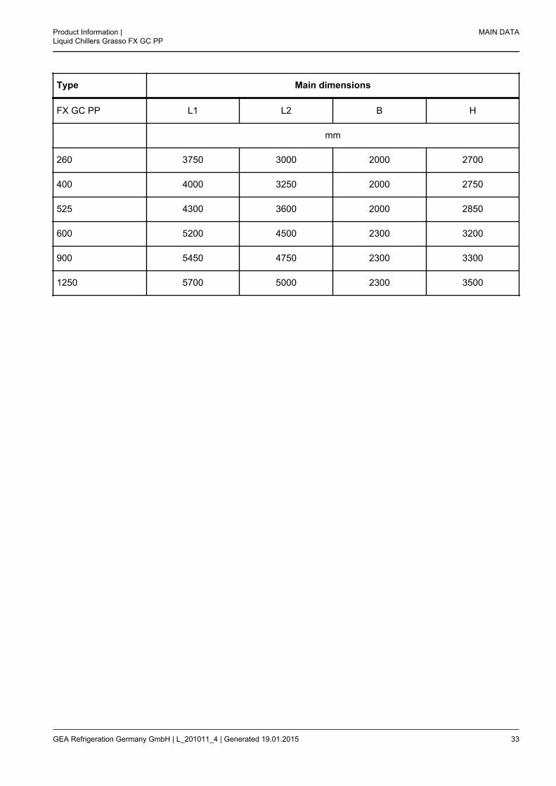
Type Main dimensions
FX GC PP L1 L2 B H
mm
260 3750 3000 2000 2700
400 4000 3250 2000 2750
525 4300 3600 2000 2850
600 5200 4500 2300 3200
900 5450 4750 2300 3300
1250 5700 5000 2300 3500
Product Information |Liquid Chillers Grasso FX GC PP
MAIN DATA
GEA Refrigeration Germany GmbH | L_201011_4 | Generated 19.01.2015 33

2.3.2 FX GC PP 520 duo to FX GC PP 1800 duo
fig.13: Set drawing FX GC PP duo
I secondary refrigerant inlet of evaporator
II secondary refrigerant outlet of evaporator
III Heating agent inlet of condenser
IV Heating agent outlet of condenser
V Blow-off line, safety valve
Type Main dimensions
FX GC PP duo L1 L2 B H
mm
520 duo 4100 3000 2000 2350
650 duo 4400 3250 2000 2450
800 duo 4600 3600 2200 2600
900 duo 5100 4500 2200 3150
MAIN DATA Product Information |Liquid Chillers Grasso FX GC PP
34 GEA Refrigeration Germany GmbH | L_201011_4 | Generated 19.01.2015

Type Main dimensions
1050 duo 5500 4750 2200 3150
1200 duo 6200 5400 2300 3300
1500 duo 6700 5900 2300 3700
1800 duo 7100 6400 2300 3800
Product Information |Liquid Chillers Grasso FX GC PP
MAIN DATA
GEA Refrigeration Germany GmbH | L_201011_4 | Generated 19.01.2015 35
2.4 Capacity calculation
The selection of the matching chiller is made with theaid of the GUD design software by entering thedesired operating parameters.
2.5 Pressure losses
Precise calculation of the cooling and heating agentside pressure losses of the evaporator and con-denser is carried out using the GUD design software.Water or brine can be used as cooling and heatingagents after their compatibility with the material com-binations of the evaporator and the pipeline that is tobe connected has been established.
MAIN DATA Product Information |Liquid Chillers Grasso FX GC PP
36 GEA Refrigeration Germany GmbH | L_201011_4 | Generated 19.01.2015

3 INSTALLATION
3.1 Installation
3.1.1 Delivery
Shipment is made in the type of packing stipulated inthe order. The chiller is generally supplied withoutpacking.The chiller has an inert gas filling (nitrogen, 0.5 baroverpressure) in the refrigerant circuit.The heat exchanger connections are closed.
Warning!
The compressors of the chiller are notcharged with oil, therefore the chillermust not be started before it is prop-erly installed and commissioned.
3.1.2 Basic information for installation
All foundation calculations, the selection of materialsand the soil analysis are the owner’s responsibility.
Caution!
Make sure that substances escapingfrom leaks do not reach into the soil,groundwater or surface water (FederalWater Act WHG).
The lifting of the chiller for alignment must only bedone on the support profiles or by means of crane. Ifsmall hoists are used (e.g. hydraulic hoists) for thispurpose, ensure that the chiller is evenly lifted by twosmall hoists at a time in the transverse direction.Outside influences (vibrations, jolts) must be avoi-ded.The welding seem must be inspected in accordancewith the Pressure Equipment Directive after weldingwork by the customer or operator at connections ofpipe lines and flanges.
3.1.2.1 Information regarding installa-tion in machinery room
The chillers have to be installed in closed machinerooms and on a level surface. Provide enough spacefor maintenance work.
Unless other order-related limitations have to betaken into account, the admissible ambient tempera-ture in operation is +5 to +40℃.
Hint!
The relevant regulations must beobserved when designing the machineroom and the safety equipment. Forfurther information on machine roomsituation, please consult our brochure"Machine room situation and fillingvolumes for NH3 refrigeration installa-tions according to accident preventionregulations".
3.1.2.2 Rigid installation
After the chiller has been placed on the surface,determine the deviations from the parallelity thathave to be maintained. Deviation from the horizontalplane should not exceed 1.5 mm/m.
3.1.2.3 Installation of the Screw Com-pressor for Insulation againstStructure-borne Sound
For installation on intermediate ceilings, matchedvibration decoupling must be carried out on the ceil-ing construction.The vibration isolators supplied have to be fixed tothe foundation bolts during assembly. Please consultthe drawing of the chiller for further information aboutthe layout and position of the holes for attaching thevibration isolators (order documentation). Refrigerantand heat carrier lines and their connections have tobe designed to withstand certain oscillations.The orientation of the coupling is to be checked inevery case before or as part of start-up and to becorrected in the event of deviations.
Product Information |Liquid Chillers Grasso FX GC PP
INSTALLATION
GEA Refrigeration Germany GmbH | L_201011_4 | Generated 19.01.2015 37

3.1.2.4 Electrical connection
Danger!
Contact with live components is pro-hibited.Produce the earth connection accord-ing to the designation in the generalassembly drawing. See chapter "Des-ignation of the earth connection".
Before beginning the work, it must be ensured thatall parts to be connected are voltage free, e.g. byremoving the main fuse in all phases.The insulation resistance of the electrical tools andfixtures and wiring is to be checked. The connectionmay only be undertaken if this value lies in the allow-able range.All electrical connections must be established and allelectrical consumers/sensors must be connectedaccording to the circuit diagram.
3.1.2.5 Sound insulation, weather pro-tection
If the chiller is intended for outside installation, itmust be equipped with a suitable casing for soundand weather protection by the customer. Theweather protection must provide sufficient protectionfor the machine with regard to the climatic conditionsat the installation location.
Hint!
The chiller is not intended for unpro-tected outside installation. Protectionagainst outside influences, especiallydirt, dust and moisture (wetness) isessential.
GEA Refrigeration Germany GmbH will not acceptliability for damage due to incorrect outdoor installa-tion.
3.1.2.6 Air-cooled condenser andevaporation condenser for GGLP and GC VP series
If an air-cooled condenser or evaporation condenseris used, certain points must be observed:The condenser is not integrated in the liquid chiller; itis installed separately. It is usually installed on theroof of the building.
The connection between the liquid chiller and thecondenser must be made on site and the necessaryfittings also mounted on site.Take summer and winter operating conditions withrespect to refrigerant displacements into considera-tion in line with local circumstances.Provide for the installation of a refrigerant collector.
3.1.3 Secondary refrigerant system
After the chiller has been aligned, it can be connec-ted on the secondary refrigerant side. The pipingsystem for the secondary refrigerant connectionsmust be installed on site by the plant engineer.If the chiller is mounted on vibration isolators, thewater lines must be connected to the evaporatorusing flexible connections. Please refer to the draw-ing in the supply documentation for the dimensionsand position of the water connections to the evapora-tor.
• The evaporator should be installed on the pres-sure side of the pump.
• Arrange a dirt collector immediately upstream ofthe evaporator (recommended mesh size 0.5mm).
• The volume of secondary refrigerant should bekept at a constant level.
3.1.4 Heating agent system
After the chiller has been aligned, it can be connec-ted on the heating agent side. The piping for theheating agent connections must be installed on siteby the plant engineer.If the chiller is mounted on vibration isolators, thewater lines must be connected to the evaporatorusing flexible connections. The size and position ofthe water connections for the condenser are indica-ted in the drawing contained in the order documenta-tion.
• Install the condenser on the pressure side of thepump.
• Arrange a dirt trap immediately upstream of thecondenser (recommended mesh size 0.5 mm).
• Check the water quality.
INSTALLATION Product Information |Liquid Chillers Grasso FX GC PP
38 GEA Refrigeration Germany GmbH | L_201011_4 | Generated 19.01.2015

3.1.5 Water pipes
• All pipes must be installed with flexible connec-tions, separate from the chiller unit. No additionalstatic or dynamic loads must be applied to thechiller connections.
• Make sure that vibrations cannot be transmitted.
• Charging and draining must be possible.
• The pipes must be flushed before connecting.This is carried out to remove soiling, foreign par-ticles and welding residue from the system.
3.1.6 Refrigerant lines
• FX GC PPChillers of the FX GC PP series are deliveredwith complete refrigerant piping, tested and filledwith nitrogen on the refrigerant side.The blow-off lines for the safety valves are to beinstalled and connected on site (by the client)As the chiller unit is mounted on vibration isola-tors, blow-off lines for connection to the chillershould be flexible.Chiller units with larger cooling capacities aresupplied partly disassembled if they exceed thepermitted transportation dimensions. On-siteassembly is carried out according to the order-dependent documentation supplied, in particularthe P+I diagram and the unit drawing.
• Evaporators FX GC VP / LP (on request)The refrigerant side pipes of the evaporator arefactory-tested, sealed and charged with nitrogen.The pressure line connection between compres-sor and condenser and the liquid line betweencondenser and evaporator injection must beinstalled, connected and tested on site (by theclient).The blow-off lines for the safety valve must beinstalled and connected on site (by the client).All pipes for connection to the chiller should beflexible.
3.1.7 Electrical installation
The chiller has been designed for plug-in, reliableautomatic operation.Connections and almost all external connections arepre-wired at the factory.
In principle, all the connections must be made inaccordance with the electrical diagram supplied.
Danger!
Contact with live components is pro-hibited.
Before beginning the work, it must be ensured thatall parts to be connected are voltage free, e.g. byremoving the main fuse.Connections to the chiller must be flexible and free ofloads.Dimensioning of the inlet pipe cross-sections mustbe according to DIN VDE 100 Part 520.Some external components, such as the secondEMERGENCY STOP switch, the ammonia sensor,the water pump flow switch, and the fans of themachine house, must be connected by the systemerector on site.
Product Information |Liquid Chillers Grasso FX GC PP
INSTALLATION
GEA Refrigeration Germany GmbH | L_201011_4 | Generated 19.01.2015 39

3.1.8 Installation information
3.1.8.1 Foundation plan
fig.14: Foundation plan
I Secondary refrigerant inlet
II Secondary refrigerant outlet
III Heating agent inlet
IV Heating agent outlet
1) Primary control side Grasso FX GC
Dimensions for W and L, see table chiller main dimensionsThe dimensions required for the installation of the chillers can be found in the order-specific drawing.For single and multiple installations, are to adhere the spacings.Leave a maintenance space of 0.8 m above the chiller.Provide clearance for suitable lifting gear in order to dismantle subassemblies for repair.
INSTALLATION Product Information |Liquid Chillers Grasso FX GC PP
40 GEA Refrigeration Germany GmbH | L_201011_4 | Generated 19.01.2015

3.2 SECONDARY REFRIGERANTSYSTEMS ON RECIPROCATINGCHILLERS
Capacity control on reciprocating chillers takes placeincrementally so that the secondary refrigerant tem-perature responds in the same manner.When the system charge is large enough, tempera-ture control usually takes place on the return flow.
The required secondary refrigerant system chargedepends on:
• Cooling capacity per power step
• Allowed restart time of compressor drive motor
• Temperature control requirements(See buffer tank size calculation.) The secondaryrefrigerant supply temperature can only be accu-rately controlled if a properly sized buffer tank is fit-ted in the chiller outlet.
3.2.1 Single chiller, single pump systems
fig.15: Single chiller, single pump systems
1 Consuming devices
2 Mixing/buffer tank
3 incorrect
4 better
5 best
R Return
S Supply
The construction of the buffer tank should ensure optimum mixing of the entering cooled secondary refrigerantwith the existing secondary refrigerant in order to achieve appropriate cooling and warming in the same timeframe.
Theoretical calculations for sizing mixing/buffer tanksTo prevent overheating of the compressor motor, switching frequency should be limited to a maximum of 1 per10 minutes. Installing a mixing/buffer tank guarantees accurate control of the secondary refrigerant outlet tem-perature.
Product Information |Liquid Chillers Grasso FX GC PP
INSTALLATION
GEA Refrigeration Germany GmbH | L_201011_4 | Generated 19.01.2015 41

mbuffer(kg) · Cpsecondary refrigerant(kJ/kgK) · 2 · Δt(K) =
Qomin(kW) · reactivation interval) (s)
----------------------------------------------------------------2
(kJ)
Qomin is the minimum cooling capacity before switching off (kW)
mbuffer = Vbuffer(m³) · ρ secondary refrigerant(kg/m³) (kg)
Vbuffer req. =Qomin ·150
-----------------------------------psecondary refrigerant · Cρ secondary refrigerant · Δt
(m³)
fig.16: Compressor switching frequency
1 Temperature
2 Time
3 restart (after 10 minutes)
4 Temperature setpoint
5 Switching state of the compressor
6 Δ tcontrol
7 Δ tcontrol
8 OUT
9 IN
10 Buffer
11 Heating
12 Cooling
INSTALLATION Product Information |Liquid Chillers Grasso FX GC PP
42 GEA Refrigeration Germany GmbH | L_201011_4 | Generated 19.01.2015

3.2.2 Single chiller, double-pump systems
The chiller system is independent of the consumer system by means of an equalising/connecting tank.
Hint!
Ensure that the chiller pump flow is always (at least 20 %) greater than the total pump flow ofthe consumer system.
fig.17: Single chiller, double-pump systems
1 Chiller group
2 Equalising / Connecting Tank
3 < 5°C switch-off of the chiller group by the controller
4 > 7°C switch-on of the chiller group by the controller
5 Consuming devices
6 Controller
7 Mixing/buffer tank
R Return
S Supply
Product Information |Liquid Chillers Grasso FX GC PP
INSTALLATION
GEA Refrigeration Germany GmbH | L_201011_4 | Generated 19.01.2015 43

3.2.3 Multi chiller, double-pump systems
The chiller system is independent of the consumer system by means of an equalising/connecting tank.
fig.18: Multi chiller, double-pump systems
1 Main PLC
2 Under PLC
3 Unit n
4 Unit 2
5 Unit 1
6 Equalising / Connecting Tank
7 < 5°C switch-off of the chiller group by the controller
8 > 7°C switch-on of the chiller group by the controller
9 Consuming devices
10 Controller
11 Mixing/buffer tank
R Return
S Supply
Hint!
Ensure that the chiller pump flow is always (at least 20 %) greater than the total pump flow ofthe consumer system.
INSTALLATION Product Information |Liquid Chillers Grasso FX GC PP
44 GEA Refrigeration Germany GmbH | L_201011_4 | Generated 19.01.2015

Unlike the mixing tank, the equalising tank should guarantee laminary flow to obtain stratification of the warmand cold secondary refrigerant. The inlets should be executed in such a manner that no impulse will be intro-duced and the secondary refrigerant velocity in the tank should be less than:
2300 x J (m²/s)
V < ------------------------ (m/s)
d Tank (m)
J is the kinematic viscosity of the secondary refrigerant.The chiller capacity is controlled by measuring the chilled secondary refrigerant temperature at TT1. Fewer con-sumers will cause the consumer flow to decrease, thus the dominant flow of the chilled secondary refrigerant willcreate an upflow in the equalising tank.When the setpoint minus Δ t is reached at minimum capacity, TT3 will switch off one chiller group. When theconsumer flow increases, due to its dominance it will create a downflow in the equalising tank. As soon as thewarm return secondary refrigerant arrives with a temperature of setpoint plus Δ t at TT2, a chiller group switcheson. Summary: TT1 takes care of chiller capacity control and TT2 & TT3 take care of switching on & off the chillergroup. There is a problem when both consumer and chiller flows are equal and supply temperature is too low(this can occur when the consumer pump control is defective). In this case, temperature in the equalising/connecting tank stays constant, TT2 & TT3 do not react, and the chiller keeps running at lowest capacity. Only inthis case can TT1 switch off the chiller group. The permission to do so comes from flow monitors 1 and 2, whichmust be in "no-flow" position.
Product Information |Liquid Chillers Grasso FX GC PP
INSTALLATION
GEA Refrigeration Germany GmbH | L_201011_4 | Generated 19.01.2015 45

3.3 Transport (crane transport)
Warning!
The chiller units are not intended for transport with a fork lift truck!
Ammonia liquid chillers are high-quality products which must be handled with extreme care during transport. Pro-tect the equipment from impacts and put it down carefully.
Danger!
Make certain there is no one under the suspended load during transport with the crane!
When transported by crane, the chiller must have the same position (frame downwards) as in operation.
Caution!
It is prohibited to strap liquid chillers to any fittings or pipes or to the eyebolts/lugs on thecompressor, electric motor, heat exchanger or switching cabinet.
Use the four carrier eyes on the base frame as lifting points for crane transport. Only use the lifting points provi-ded.The lifting points are marked!
fig.19: Designation of the lifting points
Take special care not to attach the ropes near to small nominal diameter pipes or to insulation and not to dam-age them. To prevent damage, attach cross-arms to the ropes.
INSTALLATION Product Information |Liquid Chillers Grasso FX GC PP
46 GEA Refrigeration Germany GmbH | L_201011_4 | Generated 19.01.2015

fig.20: Transport
1 Cross-arm
Make suitable arrangements (timber or Armaflex support) to avoid damage to the surface. Shackles must beused.
fig.21: Shackles
Product Information |Liquid Chillers Grasso FX GC PP
INSTALLATION
GEA Refrigeration Germany GmbH | L_201011_4 | Generated 19.01.2015 47

Warning!
Chillers must be adequately protected from external influences during transport.
Position the chiller on the transport vehicle in such a way that it is prevented from sliding, tilting or falling down.Load securing is preferably carried out by lashing to the specified points. The pipes and equipment parts of thechiller must not be stepped on. Components must be secured against vibrations. The competent staff member orthe company is responsible for ensuring transport safety.
INSTALLATION Product Information |Liquid Chillers Grasso FX GC PP
48 GEA Refrigeration Germany GmbH | L_201011_4 | Generated 19.01.2015

4 MAINTENANCE INSTRUCTIONS
4.1 Maintenance schedule for liquidchiller
The maintenance schedule listed below indicates theoperating hours at which maintenance activitiesshould be carried out. For most of the maintenancework, the chiller unit must be disconnected. To avoidshutting down the system at inconvenient times,such maintenance work should be carried out duringregular shut-downs as far as possible.To reduce maintenance costs, we have set up theschedule so that various kinds of work can be carriedout at the same time.It is advisable to service the chiller unit once a year,irrespective of the number of operating hours.Chiller unit maintenance must be carried out by theplant engineer/client in accordance with the enclosedschedule.
• After 100 operating hours: Change the lubricat-ing oil and carry out compressor maintenance(see compressor manual)
• Replace the disposable suction gas filter on thecompressor with the replacement filter providedafter a maximum of 100 hours. Check the tight-ening torques of the coupling pins.
• Every 2,500 hours: Inspection and maintenanceof the liquid chiller unit
• Every 10,000 hours: General inspection andmaintenance of the liquid chiller unit
4.2 Regular maintenance
2,500-hour (or annual) maintenance:
1. Inspection and maintenance of the compressor
2. Check that the chiller unit is level (adjustment ofthe vibration insulators if necessary)
3. Inspect water piping flanged connections forstress
10,000-hour maintenance:
1. Carry out the 2,500-hour maintenance
2. Carry our general inspection of the compressorand maintain compressor as described in thecompressor manual.
4.3 Machine room information
When selecting a suitable installation site for thechiller, take the following aspects into consideration:
• There should be no danger that the equipmentcan be damaged by in-plant transport and han-dling operations.
• Sufficient space must be available for visualinspection and maintenance work on the equip-ment.
• The floor on which the equipment is set up mustbe such that ammonia and oil cannot seep in theground.
The accident prevention directive "Refrigerating sys-tems, heat pumps and chillers" BGVD4, (see Art. 16)stipulates additional requirements for the installationof ammonia chillers in order to guarantee that suchequipment is operated safely.You will find more information on the machine roomsituation in our brochure "Installing liquid chillers inthe member states of the European Union - EN 378requirements".
4.4 Personal protection
The company shall provide personal safety equip-ment against exposure to refrigerant. This equipmentshall be stored ready-for-use outside the hazardousareas in an easily accessible manner.Safety equipment for at least two persons should beavailable.Safety equipment for ammonia:
– Safety gloves
– Safety goggles
– Respiratory equipment with filterSafety systems:To ensure a high level of safety against leakingammonia
– Ammonia warning systems and
– Absorption systemscan be ordered.
Product Information |Liquid Chillers Grasso FX GC PP
MAINTENANCE INSTRUCTIONS
GEA Refrigeration Germany GmbH | L_201011_4 | Generated 19.01.2015 49

5 SPECIFICATION
5.1 FX GC PP NH3
5.1.1 Technical Data
Rated speed min-1
Refrigeration capacity acc. to EN 12900 and DIN 8976 kW
Power consumption kW
Condenser rating kW
Secondary refrigerants
Secondary refrigerant inlet oC
Secondary refrigerant outlet oC
Heating agents
Heating agent inlet oC
Heating agent outlet oC
Condensing temperature oC
Flow rate sec. secondary refrigerant m³/h
Flow rate sec. heating agent m³/h
Main dimensions of chiller unit
Length mm
Width mm
Height mm
Refrigerant charge kg
Oil filling amount l
Shipping weight kg
Operating weight kg
Specification Product Information |Liquid Chillers Grasso FX GC PP
50 GEA Refrigeration Germany GmbH | L_201011_4 | Generated 19.01.2015

5.1.2 Package
Description Ammonia liquid chiller with reciprocating compressor, evaporator andcondenser in execution as plate heat exchanger, as a compact, completefactory packaged unit, ready for connection on site.
Compressor configuration Reciprocating compressor Grasso open-type execution with multi-stagecapacity control by cylinder offloading. The compressor is equipped withintegrated gas suction filter, solenoid valves for capacity control, oilheater, suction and discharge oil filters, back-pressure independent over-flow valve and partially loaded start. A works certificate for the test run ofthe compressor is included.
Compressor type
Liquid separator type horizontal
Valves on suction side Stop valves on suction side
Valves on pressure side Stop valve(s) on discharge side
Wiring
Painting Protective paint system S 2.15 acc. to EN ISO 12944-5 for environmentalconditions C2 acc. to EN ISO 12944-2.
Colour RAL 5014 dove blue
Insulation type Suction pipe and liquid separator insulated with Armaflex
Controller
Product Information |Liquid Chillers Grasso FX GC PP
Specification
GEA Refrigeration Germany GmbH | L_201011_4 | Generated 19.01.2015 51

Controller type Chiller unit control GSC TP (touch panel)Control on:
• Initial secondary refrigerant temperatureLimit values:
• Suction pressure, condenser pressure, motor currentModes:
• Control type: central/local, type of start-up: auto/manual, capacityregulation: auto/manual
The main functions of the PLC are:
• Initial temperature control of the secondary refrigerant
• Electronic aggregate protection and record of operating hours
• Release contacts for secondary refrigerant pump and condenser sys-tem
• Operating messages and all analogue values are displayed
• Fault messages for operating control, status lamp and text
• Potential-free status reports of the unit for /DDC (unit ready, unit inoperation, multiple fault).
Controller display Display integrated in controller
Controller arrangement Integrated in power panel
Controller communication Standard MPI interface
Display language English
Number of pressure sensors 4
Mounting of pressure sensors in tube
Number of temperature probes 6
Flow switch for secondary refriger-ant
Mechanical flow switch, delivered separately
Selection of flow switches for cool-ing medium
without flow switch
Drive motor Drive motor
Motor type Low voltage motor IP 23
Design IMB 3
Number of poles
Specification Product Information |Liquid Chillers Grasso FX GC PP
52 GEA Refrigeration Germany GmbH | L_201011_4 | Generated 19.01.2015

Protection classification IP23
Nominal motor capacity kW
Rated voltage 3 x 400 V ± 5%
Frequency 50
Rated current A
Starting current / rated current (withDOL starting)
Switch on mode star / delta
Type of power supply Switching cabinet, protection class IP 54, completely wired internally,main switch gear assembly, fuse disconnect, circuit breaker for drivemotor, protection for auxiliary motor including thermal overcurrent triggerand fuses, control transformer with double control circuit fuse on primaryand secondary side, 24 V DC power supply,
Cable entry point at the bottom
Evaporator
Operating pressure of evaporator 16 bar
Plate heat exchanger of modular semi-welded design; secondary refrigerant ports are complete with flangesand counter flanges.
Cassette material of evaporator AISI ...
Pressure drop < 80 kPa
Condenser
Operating pressure of evaporator 23 bar
Plate heat exchanger of modular semi-welded design; cooling medium ports are complete with flanges andcounter flanges.
Cassette material of condenser AISI ...
Pressure drop < 80 kPa
Safety devices
Type Double safety valve with change-over valve
Change-over valve 1
Product Information |Liquid Chillers Grasso FX GC PP
Specification
GEA Refrigeration Germany GmbH | L_201011_4 | Generated 19.01.2015 53

Number of overflow valves 1
Approval and documentation
Approval for chiller Work's Certificate, Certificate of Conformity acc. to Machine Directive98/37/EG. Calculation and manufacture acc. to AD 2000 and EN 378.
Approval pressure equipment Certificate of Conformity acc. to Pressure Equipment Directive (PED)97/23/EG. Calculation and manufacture acc. to AD 2000 and EN 378.
Non-destructive testing 10 % non-destructive welding test acc. to EN 1435
Documentation consisting of Standard documentation
Language of documentation English
Sets of documentation 2
*** Options (included in price) ***
5.1.3 Not included in scope of delivery
Not included in scope of delivery Foundations, pipes on water side, spare parts and special tools, refriger-ant and lubricating oil, performance test and start up.
Specification Product Information |Liquid Chillers Grasso FX GC PP
54 GEA Refrigeration Germany GmbH | L_201011_4 | Generated 19.01.2015

5.2 FX GC PP duo NH3
5.2.1 Technical Data
Rated speed min-1
Refrigeration capacity acc. to EN 12900 and DIN 8976 kW
Power consumption kW
Condenser rating kW
Secondary refrigerants
Secondary refrigerant inlet oC
Secondary refrigerant outlet oC
Heating agents
Heating agent inlet oC
Heating agent outlet oC
Condensing temperature oC
Capacity of compressor 1 max. kW
Capacity of compressor 2 max. kW
Power consumption compressor 1 max. kW
Power consumption compressor 2 max. kW
Flow rate sec. secondary refrigerant m³/h
Flow rate sec. heating agent m³/h
Main dimensions of chiller unit
Length mm
Width mm
Height mm
Refrigerant charge kg
Product Information |Liquid Chillers Grasso FX GC PP
Specification
GEA Refrigeration Germany GmbH | L_201011_4 | Generated 19.01.2015 55

Oil filling amount l
Shipping weight kg
Operating weight kg
Specification Product Information |Liquid Chillers Grasso FX GC PP
56 GEA Refrigeration Germany GmbH | L_201011_4 | Generated 19.01.2015

5.2.2 Package
Description Ammonia liquid chiller with 2 reciprocating compressors, evaporator andcondenser executed as a plate heat exchanger, as a compact, completefactory packaged unit, ready for connection on site.
Compressor configuration 2 Reciprocating compressors Grasso …………….., Grasso ……………..open-type execution with multi-stage capacity control by cylinder off-loading. The compressor is equipped with integrated gas suction filter,solenoid valves for capacity control, oil heater, suction and discharge oilfilters, back-pressure independent overflow valve and partially loadedstart. A works certificate for the test run of the compressor is included.
Compressor type Grasso …………../……………
Liquid separator type horizontal
Valves on suction side Stop valves on suction side
Valves on pressure side Stop valve(s) on discharge side
Wiring Wiring
Painting Protective paint system S 2.15 acc. to EN ISO 12944-5 for environmentalconditions C2 acc. to EN ISO 12944-2.
Colour RAL 5014 dove blue
Insulation type Suction pipe and liquid separator insulated with Armaflex
Controller
Product Information |Liquid Chillers Grasso FX GC PP
Specification
GEA Refrigeration Germany GmbH | L_201011_4 | Generated 19.01.2015 57

Controller type Chiller unit control GSC TP (touch panel)Control on:
• Initial secondary refrigerant temperatureLimit values:
• Suction pressure, condenser pressure, motor currentModes:
• Control type: central/local, type of start-up: auto/manual, capacityregulation: auto/manual
The main functions of the PLC are:
• Initial temperature control of the secondary refrigerant
• Electronic aggregate protection and record of operating hours
• Release contacts for secondary refrigerant pump and condenser sys-tem
• Operating messages and all analogue values are displayed
• Fault messages for operating control, status lamp and text
• Potential-free status reports of the unit for /DDC (unit ready, unit inoperation, multiple fault).
Controller display Display integrated in controller
Controller arrangement Integrated in power panel
Controller communication Standard MPI interface
Display language English
Number of pressure sensors 8
Mounting of pressure sensors in tube
Number of temperature probes 9
Flow switch for secondary refriger-ant
Mechanical flow switch, delivered separately
Selection of flow switches for cool-ing medium
without flow switch
Drive motor(s)
Motor 1
Design IMB 3
Number of poles
Specification Product Information |Liquid Chillers Grasso FX GC PP
58 GEA Refrigeration Germany GmbH | L_201011_4 | Generated 19.01.2015

Protection classification IP23
Nominal motor capacity kW
Rated voltage 3 x 400 V ± 5%
Frequency 50
Rated current A
Starting current / rated current (withDOL starting)
Motor 2
Design IMB 3
Number of poles
Protection classification IP23
Nominal motor capacity kW
Rated voltage 3 x 400 V ± 5%
Frequency 50
Rated current A
Starting current / rated current (withDOL starting)
Switch on mode star / delta
Type of power supply Switching cabinet, protection class IP 54, completely wired internally,main switch gear assembly, fuse disconnect, circuit breaker for drivemotor, protection for auxiliary motor including thermal overcurrent triggerand fuses, control transformer with double control circuit fuse on primaryand secondary side, 24 V DC power supply,
Cable entry point at the bottom
Evaporator
Operating pressure of evaporator 16 bar
Plate heat exchanger of modular semi-welded design; secondary refrigerant ports are complete with flangesand counter flanges.
Cassette material of evaporator AISI ...
Product Information |Liquid Chillers Grasso FX GC PP
Specification
GEA Refrigeration Germany GmbH | L_201011_4 | Generated 19.01.2015 59

Pressure drop < 80 kPa
Condenser
Operating pressure of evaporator 23 bar
Plate heat exchanger of modular semi-welded design; cooling medium ports are complete with flanges andcounter flanges.
Cassette material of condenser AISI ...
Pressure drop < 80 kPa
Safety devices
Type Double safety valve with change-over valve
Change-over valve 1
Number of overflow valves 1
Approval and documentation
Approval for chiller Work's Certificate, Certificate of Conformity acc. to Machine Directive98/37/EG. Calculation and manufacture acc. to AD 2000 and EN 378.
Approval pressure equipment Certificate of Conformity acc. to Pressure Equipment Directive (PED)97/23/EG. Calculation and manufacture acc. to AD 2000 and EN 378.
Non-destructive testing 10 % non-destructive welding test acc. to EN 1435
Documentation consisting of Standard documentation
Language of documentation English
Sets of documentation 2
*** Options (included in price) ***
5.2.3 Not included in scope of delivery
Not included in scope of delivery Foundations, pipes on water side, spare parts and special tools, refriger-ant and lubricating oil, performance test and start up.
Specification Product Information |Liquid Chillers Grasso FX GC PP
60 GEA Refrigeration Germany GmbH | L_201011_4 | Generated 19.01.2015

Product Information |Liquid Chillers Grasso FX GC PP
Specification
GEA Refrigeration Germany GmbH | L_201011_4 | Generated 19.01.2015 61