Linear Motion Power Transmission Design Guide 02
274
PJLMPTDG - 02
-
Upload
ravindra-kirange -
Category
Documents
-
view
186 -
download
6
Transcript of Linear Motion Power Transmission Design Guide 02

screw jacks • linear actuators • screw drives • bevel gearboxes • reduction gearboxes • couplings & drive shafts • electric motors • motion control PJLMPTDG - 02
PowerJacksLimitedMain Sales Office and ProductionSouth Harbour RoadFraserburgh AB43 9B2Scotland UK
t +44 (0) 1346 513131f +44 (0) 1346 516827e [email protected]
linearmotion
andpow
ertransm
issiondesig
nguide
distributed by:
power jacks worldwide
www.powerjacks.com
PO
WE
R JA
CK
S

1
section index
Section Index
1. Screw Jacks (Mechanical Actuators)Cubic Metric Machine Screw ActuatorsMetric and Imperial Machine Screw ActuatorsStainless Steel Actuators - Metric and ImperialMicro-Miniature ActuatorsBall Screw Actuators - Metric and ImperialRoller Screw and Special Actuators
2. Linear ActuatorsEMA - Actuator Series
Rolaram Actuator Series
3. Screw DrivesSpiracon Roller Screw
4. Bevel Gearboxes - Neeter DriveP-Range Series 2000 and 4000
N-Range Series 35, 37, 38, 39 and 40BA-Range Series L, H, and K
5. Reduction GearboxesHelical Worm GearboxesIn-Line Helical Gearboxes
6. Couplings and Drive ShaftsJaw and Gear Flexible Couplings
Drive ShaftsPlummer Blocks
Hand Wheels
7. Electric MotorsStandard 3-Phase MotorsBrake MotorsMotors with Encoders and Forced Ventilation
8. Motion ControlRotary Limit Switches
Proximity and Electro-mechanical Limit SwitchesEncoders - Incremental and Absolute
Position IndicatorsControl Panels
9. Engineers ReferenceFormulae and FactorsStandard Metric Component DataPropertiesWarranty
sectionindex

2
Picture Index
picture index
picture index
Cubic Actuators Metric Ball Screw ActuatorsMetric Actuators Stainless Steel Actuators
EMA Actuators
Ball Screw Rolaram Actuator
Roller Screw Rolaram Actuator
Roller Screw and SpecialActuators
Imperial Actuators Imperial Ball Screw Actuators Spiracon Roller Screw
Special Actuators

3
picture index
pictureindex
P-Range Bevel Gearboxes N-Range Bevel Gearboxes BA-Range Bevel Gearboxes Electric Motors
Couplings andDrive Shafts
Helical Worm Gearboxes
In-Line Helical Gearboxes Proximity and Contact LimitSwitches
EncodersRotary Limit Switches Position Indicators Engineers Reference

4
company profile
Company Profile
Power Jacks Ltd Extensive Site in Fraserburgh, Aberdeenshire
companyprofile
Power Jacks is the largest and most experienced
manufacturer of actuators and mechanical jacks in the UK.
With our range of Power Jacks and Duff-Norton actuators
you don’t just get the product, you also get the knowledge
and experience from a company that has, since 1883,
manufactured quality industrial lifting, positioning and
materials handling equipment.
On our extensive site in Fraserburgh, Aberdeenshire, we have
a wide range of engineering facilities including CAD/CAM/
CAE technology to aid engineering design and manufacture,
an advanced production control system ensuring the
optimum product flow through our comprehensive range of
conventional and CNC machining facilities, which maximises
efficiency and reduces delivery times. This is achieved with
our 100+ highly trained employees, giving Power Jacks the
capability to produce mechanical engineering of the highest
standards.
Quality is a key part of Power Jacks working philosophy and
built into the product from initial design conception, through
production, to installation and after sales service.
There are over two million of our actuators successfully in
operation world-wide. The Power Jacks Group are a globalmarket leader in Linear Actuation Systems.
By specifying a Power Jacks product you are assured of quality,
reliability, performance and value. In the United Kingdom there
are a team of highly experienced sales engineers to assist
customers with their actuation applications whether on site or
by direct communications with the Fraserburgh factory. For
overseas customers there is an extensive distributor network
world-wide.

5
company profile
Power Jacks Standard Product Range Covers:-
Machine Screw Worm Gear Actuators (Screw Jacks)
Ball Screw Actuators (Screw Jacks)
Stainless Steel Actuators (Screw Jacks)
Micro-Miniature Actuators
TracMaster Electro-Mechanical Linear Actuators
EMA Electro-Mechanical Linear Actuators
Rolaram Electro-Mechanical Linear Actuators
Mechanical Jacks
Neeter Drive Bevel Gear Boxes
Reduction Gear Boxes
Power Transmissions
Accessories for Complete Actuator Systems
Actuator Motion Control Systems
Track (Rail) Jacks
Hydraulic Jacks
Hydraulic Cylinders
Hydraulic Pumps and Tools
Both Metric and Imperial Products are available.
As well as these standard products Power Jacks has adedicated engineering team for the design of “Special”products to suit all customer requirements.
These products can be provided as individual partsor single or multiple systems with full engineeringconsultancy available as par t of the service.
companyprofile
For more information contact:
Power Jacks LtdSouth Harbour Road Fraserburgh AB43 9BZTel: +44 (0) 1346 513131Fax: +44 (0) 1346 516827email: [email protected]: http://www.powerjacks.com

6
POWER JACKSGroup
NEETER DRIVES P I R A L B E V E L G E A R B O X E S
FORTUNE™
E N G I N E E R I N G L T D
PRECISIONA C T U A T I O N S Y S T E M S
POWER JACKS
Youngs Lifting
company profile
companyprofile
Company Profile
The Power Jacks Group is an engineering group focused on providing customers with the best solution for precision linear actuation,power transmission, mechanical jacking, hydraulic jacking and engineering service. The engineering history of the group dates from1883 and the products and service are supplied to customers world-wide.
The Power Jacks Group Brings Together
Representation

1. screw jacks (mechanical actuators)
Screw Jack (Mechanical Actuator) Product SummaryTypical Applications and AccessoriesSelecting an actuatorProduct Codes
Section 1.1. Screw Jack Idea and Application Guide
POWER JACKSGroupmanufacturers of precision screw jacks, actuators and gearboxes
Sym-metric (CUBIC) Actuators25kN to 200kN capacities with Machine ScrewTranslating and Rotating screw3 gear ratios and 2 screw leads as standardAnti-backlash & Anti-rotation (keyed) options
Section 1.2.1
Sym-metric (Cubic) ActuatorsS-Series
Metric Single Face Screw Jacks (mechanical actuators)5kN to 1000kN capacities with Machine Screw or Ball ScrewTranslating and Rotating Screw in Upright and Inverted types2 gear ratios and 1 screw lead as standardBall screw units have 2 screw lead optionsAnti-backlash and Anti-rotation (keyed) options6 mounting options including trunnion and double clevis
Section 1.2.2. and 1.3.1.
Metric Single Face ScrewJacks (Mechanical Actuators)E-Series
Imperial Single Face Screw Jacks (mechanical actuators)1/2 Ton to 100 Ton capacities with Machine Screw or Ball ScrewTranslating and Rotating Screw in Upright and Inverted types2 gear ratios and 1 screw lead as standardBall screw units have 2 screw lead optionsAnti-backlash and Anti-rotation (keyed) options5 mounting options including double clevis
Section 1.2.3. and 1.3.2
Imperial Single Face ScrewJacks (Mechanical Actuators)M-Series
Metric 10kN to 1000kN capacities with Machine ScrewImperial 2 Ton to 100 Ton capacities with Machine ScrewTranslating and Rotating Screw in Upright and Inverted types2 gear ratios and 1 screw lead as standardAnti-backlash and Anti-rotation (keyed) options5 mounting options including double clevis
Section 1.2.4. & 1.2.5.
Stainless Steel (E) Metric and(M) Imperial (Single Face)Actuators
Metric or ImperialUp to 450kg capacities with Machine ScrewBalanced or continuous dial types
Section 1.2.6.
Micro-Miniature Actuators
Roller Screw & Special ActuatorsRoller Screw Jacks for high duty applicationsModified screw jacks e.g. material, paint, screw lead, etc..Special additional features e.g. wear indicator, safety nuts, etc..New design tailored to exact customer requirements
Section 1.4.
High Duty andSpecial Screw Jacks
Screw Jack (Mechanical Actuator) Engineering GuideActuator performance chartsActuator product operation featuresInstallation and maintenance tips
Section 1.5.
Engineering Guide

1
screw jacks
sectionone
Contents
1. Screw Jacks (Mechanical Actuators)
1.1. Idea and Application Guide 21.1.1. Screw Jacks (Mechanical Actuator) Product Summary 2
1.1.2. Typical Applications 3
1.1.3. Selecting an Actuator 7
1.1.4. Preview of Actuator Accessories 14
1.1.5. Actuator System Selection Guide 16
1.1.6. Worksheet/Application Analysis Form 18
1.1.7. Actuator Product Codes for Ordering 19
1.2. Machine Screw Actuators 231.2.1. S-Series (Sym-metric) Actuator Models 23
1.2.2. E-Series Metric Machine Screw Actuator Models 35
1.2.3. M-Series Imperial Machine Screw Actuators Models 53
1.2.4. E-Series Metric Stainless Steel Machine Screw Actuators 67
1.2.5. M-Series Imperial Stainless Steel Machine Screw Actuators 69
1.2.6. Micro Minature Actuators 72
1.3. Ball Screw Actuators 731.3.1. E-Series Metric Ball Screw Actuators 73
1.3.2. M-Series Imperial Ball Screw Actuators 87
1.4. High Duty Cycle and Special Screw Jacks 971.4.1. High Duty Roller Screw Jacks 97
1.4.2. High Duty Cycle Ball Screw Jacks 98
1.4.3. Special Screw Jacks (Mechanical Actuators) 99
1.5. Engineering Guide 101
The Engineering Guide Section has its own detailed contents page
1.5.1. Actuator Performance 102
1.5.2. Actuator Product Operation Features 115
1.5.3. Installation and Maintenance Tips 120

2
screw jacks
sectionone
1.1. Idea and Application Guide
1.1.1. Screw Jack (Mechanical Actuator) Product Summary
Sym-metric Machine Screw ActuatorsCubic style metric actuator designed and manufactured in the UK. This actuatorwas designed with a higher thermal efficiency than conventional machine screwactuators, allowing higher duties and working temperatures, and improved mountingarrangements e.g. Upright and inver ted positions are now incorporated in onemodel.
Conventional Machine Screw ActuatorsProbably the most widely used mechanical actuator for intermittent duty cycles asthe actuator incorporates a precision worm gear set in a rugged casting deliveringpositive, precise actuation. Available in a comprehensive range including metricmodels, imperial models in standard materials or stainless steel models for specialenvironments.
Ball Screw ActuatorsThe ball screw actuator can run at higher duties and speeds than machine screwactuators through the high efficiency of the ball screw and nut. The ball screw alsoprovides longer life at load and requires less power than a machine screw actuatorfor a specified thrust. The range is available with the same number of metric andimperial variants as the machine screw range. All metric models have a ball nutsafety device as standard. A high duty cycle model for continuous operation is alsoavailable.
Miniature ActuatorsDesigned for applications which call for extremely precise very small adjustments.To achieve their high accuracy they are equipped with anti-backlash nuts as standardto minimise vertical backlash between the lifting screw and worm gear nut. Theseactuators are available with a corrosion resistant finish or in stainless steel for harshenvironments.
Special ActuatorsPower Jacks design and manufacture special actuators to suit specific customerapplications whether this requires modification or addition to a standard productor the design of a completely new actuator.
Actuators AccessoriesPower Jacks have a comprehensive range of actuator accessories including powertransmissions and motion control systems. A turn key actuation solution cantherefore be provided to the customer whether it be for singular or multipleactuator systems.
Sym-metric MachineScrew Actuator
Conventional MachineScrew Actuators
Ball ScrewActuators
MiniatureActuators
SpecialActuators
ActuatorAccessories

3
screw jacks
sectionone
1.1.2. Typical Applications
Power Jacks actuators operating successfully world-wide in a wide variety of industries including paper, food processing, nuclear, steel,transport, aerospace, communications and leisure.
Adjuster toPaper Machine
Satellite Dish Positioning Quick Hitch forExcavator Bucket Attachment
Steel Strip Tension Leveler
Roll Tensioner
12 Head HorizontalBand Saw
Plate Leveller
Particle Accelerator
Stadium Access Lift

4
screw jacks
sectionone
BiscuitMaking Machine
Screw Jack with CoilSpring Damper Unit
Headbox Adjustmenton Paper Machine
Glass PackagingMachine
Military AircraftAssembly Locating Rig
Pre-Feed and Stackingon Fibre Board Machine
Aircraft AirbridgeAccess Leveling

5
screw jacks
sectionone
Sheet Metal BundleTurnover Machine
Foam Forming MachineAero Engine Lift forTransportation Stand
RailwayCarriage Lift
Raise and Lower Dampersin Power Station Flues
Tube EndDeburring Machine
Hydospace Test Centre35 Te Pressure Vessel Lid Lift

6
screw jacks
sectionone
The applications are wide, varied and ever increasing as pneumatic and hydraulic technologies are replaced by what can be a cleaner,quieter and more reliable solution.
Access Platform Lift forAircraft Wing Manufacture
Section Rolling Machine
Aircraft Access Equipment
Strip Guide Adjusters
Printing Press
MedicalExamination Table
Actuators withShock Absorbers
Heavy DutyStraightening Machine
Double PinchBending Rolls Machine

7
screw jacks
sectionone
1.1.3. Selecting an Actuator
The following selection procedure is applicable for machine screw and ball screw actuators.
1.1.3.1. Five Step Guide to Initial Actuator Selection
Calculate Power and Torque Requirements
Select an actuator from the tables with adequate load carrying capacity and note the actuator static and dynamicefficiency for required input speed.
Step1 Actuator Input Speed
Note Actuator Input Speed should not exceed 1800 rpm.
Step 2 Operating Input Power (kW), Pin
Step 3 Operating Input Torque
Step 4 Actuator Start-Up Torque
Step 5 Mechanical Power and Torque Check
Check whether the actuator power and torque required for the application is not greater than the maximumallowable mechanical input power (P
mechanical) and Start-Up Torque at Full Load (T
s) values specified in the
actuator performance tables.
If Pmechanical
> Pin & T
s > T
ins then the actuator selected is acceptable for power requirements.
N (rpm) =Pitch (mm) * N of Starts on Lifting Screwo
/Raise Rate (mm min) *Gear Ratio
Pin
(kW) =Load (kN) * Raise Rate (mm/min)
60000 * adη adη = Dynamic Actuator Efficiency
T (Nm)N (rpm)
ino =P (kW) * 9550
in
Tins =
Load (kN) * Pitch (mm) * N of Starts on Lifting Screwo
2 * * * Gear Ratioasηπ asη = Static Actuator Efficiency

8
screw jacks
sectionone
Example Initial Actuator Selection
Application Contraints
• Load on Actuator = 15 kN in Tension
• Raise Rate required = 100 mm/min
Consider all application constraints then choose an actuator that looks suitable for the application with an actuator load rating equalto or greater than the maximum working load. For this example say a 25 kN Sym-metric Actuator (refer 1.2.1.) with translating screw,6:1 gear ratio, single star t lifting screw (6 mm lead).
Calculate Power and Torque Requirements
Step1 Actuator Input Speed
Note Actuator Input Speed should not exceed 1800 rpm.
From the Sym-metric performance tables (refer 1.2.1.1.) dynamic actuator efficiency = 0.275.(Efficiency value found by interpolating between efficiency values at input speeds higher and lower than desired input speed).
Step 2 Operating Input Power (kW), Pin
Step 3 Operating Input Torque
Step 4 Actuator Start-Up Torque
Step 5 Mechanical Power and Torque Check
Find the actuators mechanical power and torque rating from the performance data tables (refer 1.2.1.1.)
Pmechanical = 1.5 kW > Pin and Ts = 19 Nm > Tins
Therefore the actuator selected is suitable for application for initial constraints tested, fur ther analysis may be requiredto ensure the actuator is suitable for all application conditions (refer 1.1.3.1. or consult Power Jacks Ltd.)
N (rpm) =6 (mm) * (N of Starts on Lifting Screw)o1
/100 (mm min) *6 (Gear Ratio)N = 100 rpm
Pin
(kW) =* 100 (mm/min)15 (kN)
60000 * 0.275Pin = 0.091 kW
T (Nm)100 (rpm)
ino =0.091(kW) * 9550
Tino = 8.7 Nm
Tins =
15 (kN) * 6 (mm)* (N of Starts on Lifting Screws)o1
2 * * * 6 (Gear Ratio)π 0.208T
ins = 11.5 Nm
asη = 0.208 (refer 1.2.1.1.)

9
screw jacks
sectionone
1.1.3.2. Actuator Constraints for Detailed Selection
1.1.3.2.1. Lifting Screw Buckling Criteria
For compressive loads on the actuator lifting screw column strength calculations are required to check for buckling. As an actuatorselection guide use the following process:
1. Determine the maximum column length (L) for the actuator being considered (refer 1.5.1.1.).
2. Referring to the relevant column buckling chart (refer 1.5.1.1.) determine the permissible compressive load (Wp)corresponding to the column length (L) for the appropriate end constraints. This permissible compressive load is themaximum load (inclusive of shock loads) which may be applied to the actuator for a given column length.
3. Where an application involves human cargo or there is a risk to personnel, it is highly recommended that thepermissible compressive load (as calculated above) be factored by 0.7 to enhance working safety. (Equivalent to acolumn strength safety factor of 5).
Wphc = Wp * 0.7 (Permissable compressive load for personnel risk applications)
Note 1. For Ball Screw Actuators Refer 1.5.1.1.2.2. For detailed analysis of actuators and their systems (not all covered in this guide) consult Power Jacks.3. Safety factor of 3.5 for column strength's used for normal industrial cargo.
1.1.3.2.2. Lifting Screw Critical Speed
To calculate the critical speed for rotating screw actuators:
1. Refer to the appropriate critical speed chart in section 1.5.1.2., 1.5.1.3., and 1.5.1.4.
2. Select the correction factor Fcs
corresponding to the end support conditions for the application.
3. From the critical speed chart select the critical speed corresponding to the unsupported screw length (m) andthe actuator load rating (kN).
4. Calculate the limiting critical speed with the formula below.
Limiting Critical Speed = Critical screw speed * Fcs
Note Critical for speeds drive shafts refer 6.2.1.

10
screw jacks
sectionone
1.1.3.2.3. Lifting Screw Deflection
The lifting screw of an actuator mounted horizontally will deflect under its own weight to some extent. The amount of deflectiontolerable (y
T) should be less than 0.5 mm per metre.
Deflection Factors, Fsd
Fixed/Fixed. Fsd
= 8 Fixed/Fixed. Fsd
= 186 Fixed/Fixed. Fsd
= 384
L = Lifting Screw Length (mm)
d = Diameter of Lifting Screw (mm)
p = Pitch of Lifting Screw (mm)
If y < yT then the lifting screw deflection is acceptable.
Note This is only a deflection guide.For detailed analysis, including methods to reduce deflections consult Power Jacks Ltd .
1.1.3.2.4. Actuator Torque
Start up/Static torque values are listed in all performance tables. Whereas dynamic torque values are either calculated usingthe tabulated dynamic efficiencies or taken direct from torque tables where listed. For detailed actuators analysis consultPower Jacks Ltd.
1.1.3.2.5. Actuator Side Loads
It is recommended that all side loads (Fsl) are carried by guides in your arrangement and not by the lifting screw and nut. If there are
any side loads on the actuator they must not exceed those tabulated in section 1.5.1.6., and it must be noted that any such loads willadversely affect the life of the lifting screw and nut.
L L L
Deflection , y, (mm) =(d-p)Fsd
2
6 * 10 * L-9 4
1000Deflection Tolerable, y , (mm) =
T
0.5 * L
Raise
Fsl

11
screw jacks
sectionone
1.1.3.2.6. Radial Forces on Actuator Worm Shaft
For applications where an actuator is belt driven, radial force (FR) values exerted on the worm shaft must not exceed those tabulated in
section 1.5.1.6. Values are tabulated for the Sym-metric and Metric machine screw actuators and Ball Screw actuators. The values aremaximum values for the actuators at rated load regardless of worm speed or load direction.
1.1.3.2.7. Actuator Self Lowering and Drift
Most machine screw actuators are self-locking (refer 1.5.2.1.1.8.) either in the gearbox or the lifting screw however to ensure there isno self-lowering and to reduce drift due to the motor slowing a brake motor is recommended (refer 1.5.2.1.4.5.). Standard motor framesize brakes will be suitable for most applications with only slight vibration and thermal fluctuation present. Motor selection as normal.For dynamic braking consult Power Jacks.
Ball screw actuators always require a brake as their high efficiency makes them self-lowering. To calculate the brake torque required forball screw actuators:
1. Obtain the motor speed (RPM) and inertia value (Mk2 ) from the motor manufacturer.
2. Obtain the value for actuator lead and the hold back torque from the actuator performance tables.
3. Select the desired drift after the motor is turned off, note allow as much drift as possible to keep the brake size toa minimum.
4. If a gear reduction unit is used in the drive then the “reducer ratio” is equal to the gear ratio of the reducer.
5. Substitute values in the equation below and solve for the brake torque required by the motor.
Use the closest standard brake size that is greater or equal to the motor brake torque required.
Note 1. For Machine screw actuators the lowering torque 0.5 * Lifting Torque.2. Self lowering can occur in any actuator system not fitted with a brake where high levels of vibration are present
in the application.3. Power Jacks recommend the use of a brake on single actuator applications in the vertical position.
FR
Motor Brake Torque (Nm) =Reducer Ratio
+573 * Drift (mm) * Reducer Ratio
lead (mm) * RPM * Mk2Hold Back * Number of
Torque (Nm) Actuators2

12
screw jacks
sectionone
1.1.3.2.8. Multiple Actuator Configurations
Total Input Power for Actuator Systems (kW), Ps:
Gearbox Efficiency = Bevel Gearbox Efficiency * Reduction Gearbox Efficiency
Bevel Gearbox Efficiency = 95% Typical (refer to 4.0.).
Reduction Gearbox Efficiency = Consult unit details, if no reduction gearbox present assume efficiency of 100%
Note For actuators connected in-line the worm shaft can transmit up to 3 times the torque for a single actuator atits maximum capacity, except the 1820 Unit which can transmit 1.5 times the torque (refer 1.5.2.2.2.).
1.1.3.2.9. Typical System Configurations
‘H’ Configuration ‘U’ Configuration
‘H’ and ‘U’ configured actuator systems are typical and include actuators, motor, bevel gearboxes, reduction gearboxes, drive shafts,couplings and plummer blocks.
Actuator arrangements can be built in many formats with the use of bevel gear boxes which allow the direction of drive rotation to beselected on assembly. The gear boxes come in 2, 3 and 4 way drive types (refer 4.0).
P =s Arrangement Efficiency * Gearbox Efficiency
Input Power per Actuator (kW) * Number of Actuators
Number of Actuators in Arrangement 2 3 4 6 � 8
Arrangement Efficiency (%) 95 90 85 80

13
screw jacks
sectionone
1.1.3.2.10. Other System Configurations
‘U’ Configuration ‘2H’ Configuration
‘E’ Configuration ‘TF’ Configuration
‘T’ Configuration Neeter DriveBevel Gearbox
Sym-metric TranslatingScrew ActuatorMechanical linked in twoJack Actuator System
Spacer Coupling(Self Supporting)
RLS-51 Limit SwitchProvides extreme end of travel limits for Actuator System
AC Motor withintegral AC Brakeand Encoder

14
screw jacks
sectionone
1 2 3 4 5
EncoderAnti-Rotation Pin
Protective Cover
Encoder(Hollow Shaft)
PositionIndicator
50 kN Metric Actuator
Drive ShaftAdaptor
Plug-in connectorand cable
1.1.4. Preview of Actuator Accessories
1.1.4.1. End of Travel Limit Switches
Inductive proximity sensors or electro-mechanical roller plungerswitches can be used as end of travel limit switches. Thesearrangements are typically used as limits to stop the actuatoror reverse the drive motor.
Electro-mechanical roller plunger switches triggered by a nuton the lifting screw which depresses the plunger as it passes.
Inductive Proximity sensors trigger when the target nut on thelifting screw passes the sensor. The sensor sends a signal to thecontrol circuit.
Rotary limit switches can be used as end of travel limit switcheswith the option of intermediate switches as well. These units aremounted onto a screw jacks free worm shaft and offer analternative where bottom pipe mounted limit switches are notpossible e.g. rotating screw jacks. Up to 8 limit switches can beaccomodated in one unit.
1.1.4.2. Screw Jackswith Position Indicators
Position indicators can be provided on screw jacks by meansof an encoder. The encoder (incremental or absolute) ismounted on a free worm shaft and feedsback to a digitalposition indicator or other control system. The positionindicator can then be calibrated for the application in userunits e.g. millimetres of travel are displayed.
RLS-51 and SKA type rotary limitswitches can be mounted to most
screw jacks.
Electro-mechanical Inductive ProximityLimit Switches Sensors

15
screw jacks
sectionone
1.1.4.3. Anti-Rotation and Wear Monitoring
The above arrangement is for a lifting screw in compression because as the gear wears the nut moves away from the gear and towardsthe sensor. If an actuator were in tension the target ring for the sensor would be to the right of the sensor, as the nut would movetowards the gear.
The anti-rotation and wear monitor devices can be supplied together or as separate devices for Power Jacks machine screw actuators.For installation purposes both devices can be accommodated either below the actuator base (as above) or in the actuator’s shell cap.Consult Power Jacks Ltd for details.
1.1.4.4. Motor/Gearbox Adaptors
Screw Jacks can be have motors or motorised reduction gearboxes attached via motor adaptor kits. These mount the motor/gearboxunit onto an actuators free worm shaft.
Wear MonitorInductive Proximity Sensor looks for the target ring on the nut. As the gear set wears the nut and its target ring move closer to the sensor. The sensor triggers when the ring is in front of the sensor. When triggered the control system indicates that the actuator should be inspected and refurbished.
Anti-Rotation MonitorThe inductive proximity sensor generates a series of pulses from the target discs mounted on the circumference of the nut. The nut rotates at the same speed as the worm gear. If
the frequency of pulses is lower than a predetermined value or stops then the control system can inform the operator.
This can be used to indicate that the system is below speed or a jamming condition has occurred.
Actuator Bottom Pipe
Actuator Base
Anti-Rotation Target Discs
Wear Monitor Target Ring
NutNut connects to worm gear via dowel pins. This allows the
nut to rotate with the gear and follow the lifting screw as the thread in the gear wears. Note The nut is unloaded.

16
screw jacks
sectionone
1.1.5. Actuator System Selection Guide
Determine operating conditions thata system must fulfill
Remember at any time during the selection/specification of any linear actuation system consultPower Jacks Ltd for advice and/or detailed analysis at no extra cost.
Consult Power Jacks Ltd for advice
Requires synchronisation andmotion control
IndividuallyMotorised
Plan actuator system layout
Decide how many actuatorsare required
Initially select an actuator type
Check actuator suitabilityusing procedure in 1.1.3.
Repeat for number ofdifferent actuators or
differently loadedactuators in system
Mechanically Linked System(refer 1.1.3.2.8.)
Not Suitable
Re-select actuator
OK
{
I require a Linear Actuation Solution
Calculate loading conditions on eachactuator for all service conditions
17
screw jacks
sectionone
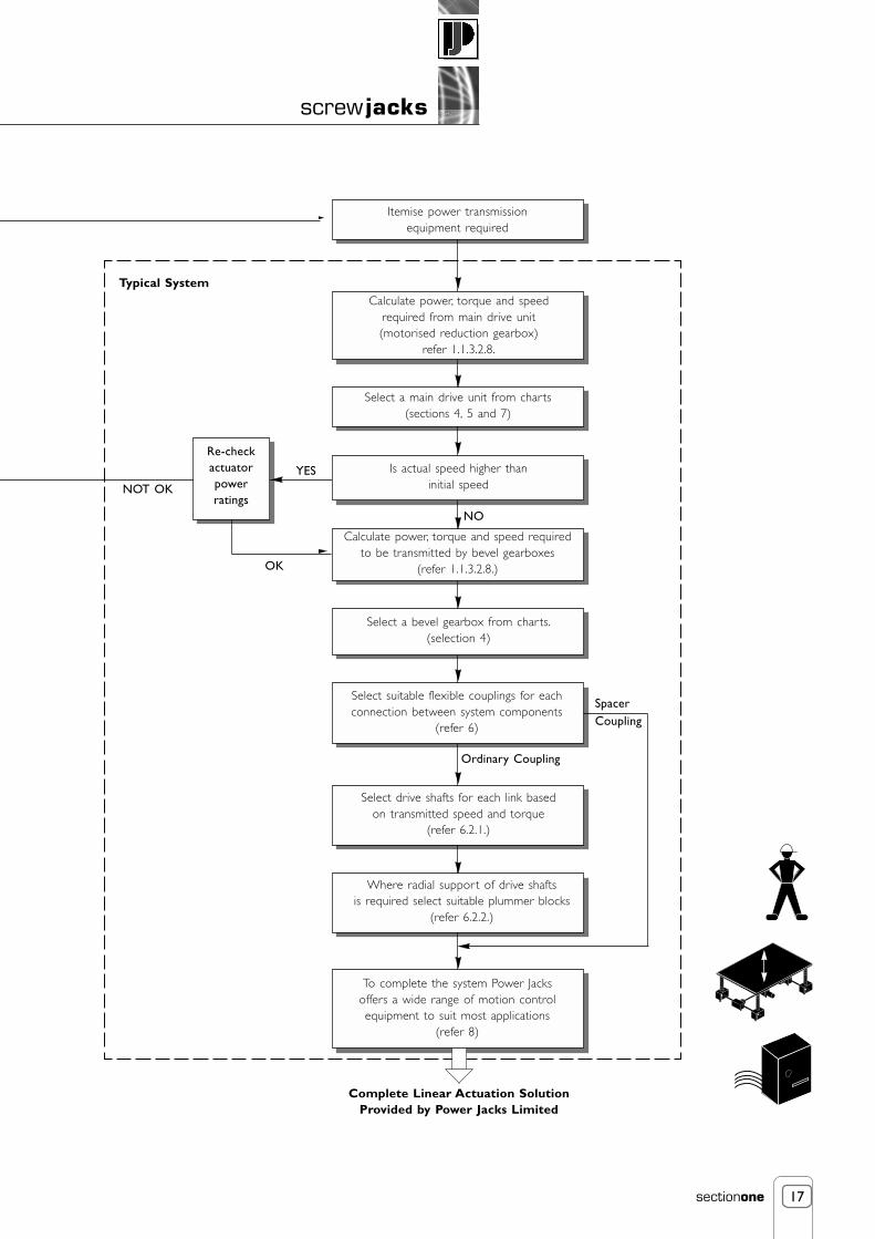
Select a main drive unit from charts(sections 4, 5 and 7)
Is actual speed higher thaninitial speed
Calculate power, torque and speed requiredto be transmitted by bevel gearboxes
(refer 1.1.3.2.8.)
Select a bevel gearbox from charts.(selection 4)
Select suitable flexible couplings for eachconnection between system components
(refer 6)
Where radial support of drive shaftsis required select suitable plummer blocks
(refer 6.2.2.)
Re-checkactuatorpowerratings
NOT OK
YES
SpacerCoupling
Itemise power transmissionequipment required
Ordinary Coupling
Select drive shafts for each link basedon transmitted speed and torque
(refer 6.2.1.)
Calculate power, torque and speedrequired from main drive unit(motorised reduction gearbox)
refer 1.1.3.2.8.
OK
Typical System
Complete Linear Actuation SolutionProvided by Power Jacks Limited
NO
To complete the system Power Jacksoffers a wide range of motion controlequipment to suit most applications
(refer 8)

18
screw jacks
sectionone
1.1.6. Worksheet/Application Analysis Form
Power Jacks engineers will be pleased to make recommendations for your specific requirements. Complete this form with as muchinformation as possible and send it to the Application Department.
Mail it to Power Jacks Ltd., Maconochie Road, Fraserburgh, AB43 8TE, Scotland.Or fax +44 (0) 1346 516827Or email [email protected].
There is no charge for this service.
Use a separate sheet to sketch your application, or send us your design drawings in complete confidence.
Type of Application
How many actuator units needed: Raise/Unit mm
How many bevel gear boxes needed:
Total working load: Working load per unit
Total static load: Static load per unit
Side load on lifting screw: Off centre load on lifting screw: kN mm
Operating cycles per hour hours per day days per week
Life expectancy: m (metres per cycle x cycles per day x days per year x years of service required)
Lifting speed desired mm/min Drive Manual Motor-driven
Load type: Guided Unguided Compression Tension Both compression and tension
Ambient conditions: Vibration Impact High temp. Low temp. Other
Type of prime mover : Electric Motor Air Motor Hydraulic Motor Manual Other
Type of actuator preferred:
Ultimate use of actuator units: In-plant Resale
Quotation desired on the following quantities: Actuator units Gear boxes
Name: Title:
Company:
Address:
Town: County: Post Code:
Country: Phone: Fax:
Note A brake is required on ball screw actuator units due to their high efficiency.
Order Checklist
To ensure you receive the required equipment, please use the following checklist before finalising your order
• Quantity
• Stroke
• Capacity
• Actuator Model
• Type of screw end(top plate, threaded end, etc)
• Submit print if special end configurationis desired
• Gear ratio
• Whether upright, inverted screw, translatingscrew or rotating screw
• Keyed screw(not standard must be specified)
• Bellows Boot
• Anti-backlash feature (machine screw actuator models only)
• Worm extension - right or left-hand or both(double extension is standard)
• Limit switch and position (state voltage - available as standardwith 250 V, 480 V, or 600 V. Also state whether switch is tobe mounted on right or left extension of worm shaft)
• Encoder
• Visual position indicator
• Control System
• Motor mounted on actuator
• Call out other special requirements in detail, or submit printwith order
• State cargo carried by actuators i.e. industrial only orhuman cargo

19
screw jacks
sectionone
1. SYM-METRIC ACTUATOR
[S]
2. TYPE[T] - Translating[R} - Rotating
3-5. RATING (kN)[025] - 25kN[050] - 50 kN[100] - 100 kN[200] - 200 kN
6-9. RAISE (mm)0000 - 9999
10. END TYPETranslating:-[C] - Clevis End[E] - Screw Thread[T] - Top Plate[A] - Plain
Rotating:-[P] - Pilot[N] - No Pilot
11. LIFTING SCREWSTART
[1] - 1 Start[2] - 2 Start *
12. GEAR RATIO[R] - Standard Ratio[1] - Option 1 Ratio[2] - Option 2 Ratio[X] - Special *
13. FEATURES[0] - None[K] - Keyed *[C] - Secondary Guide *[R] - Anti-Backlash *[V] - Inverted Screw Anti-Backlash *[Y] - Keyed Anti-Backlash *[W] - Inverted Screw Keyed Anti-Backlash *
* Cost increase as the product is a variant, this may also effect delivery.
14. ACTUATORDESIGNATION
[F] - Factory Designated *[C] - Customised Feature
15. BOTTOM PIPE[P] - Bottom Pipe[F] - No Bottom Pipe
16. LIFTING SCREW THREAD(Direction of worm rotation to raise load)
[C] - Right Hand (Clockwise)[A] - Left Hand (Anti-Clockwise) *
17. LIFTING SCREWMATERIAL
[1] - Carbon Steel[2] - Stainless Steel *
18. SCREW COVER[0] - None[B] - Bellows Boot *[T] - Telescopic *
19. SIDE ADAPTER BOLT HOLES[0] - None[1] - Left Hand *[2] - Right Hand *[3] - Both *
20. DRIVE SHAFTENDS
[B] - Standard (Both)[F] - Left Hand Only[R] - Right Hand Only
Character
Example
1 2 3 4 5 6 7 8 9 10 11 12 13 14 15 16 17 19 2018
S T 0 2 5 1 5 0 0 C 1 R K C P C 1 3 BB---
1.1.7. Actuator Product Codes for Ordering
1.1.7.1. S-Series (Sym-metric) Screw Jack Product Code

20
screw jacks
sectionone
1.1.7.2. E-Series Metric Machine Screw Jack Product Code
Example 200 kN inverted keyed translating machine screw actuator with top plate, 300 mm of raise, bellows boots fitted toprotect lifting screw and a single ended worm shaft extension on the right-hand side only.
1.1.7.2.1. Prefixes (a)
S - All Stainless Steel Metric actuator.
K - Keyed Lifting Screw
1.1.7.2.2. Basic Model (b)
TE - Threaded end on lifting screw (standard).
ME - Top Plate on end of lifting screw.
CE - Clevis End on lifting screw.
PE - Plain end, with no machining on end of lifting screw.
DE - Inverted rotating screw actuator.
UE - Upright rotating screw actuator.
CCE - Actuator unit with double clevis mounting arrangement.
Note 1. For Metric actuators with plain ended lifting screws consult Power Jacks.2. For Metric Stainless Steel actuators with varying materials and/or platings consult Power Jacks.3. For external keyed guides consult Power Jacks.
1.1.7.2.3. Capacity and Series Designations (c)
Upright Translating Metric Actuator Models
Model Number 2625 2501 1802 1805 1810 1820 1830 1850 18100
Rating (kN) 5 10 25 50 100 200 300 500 1000
Inverted Translating Metric Screw Actuator Models
Decrease the upright model number by 1, e.g. 1804, 50 kN inverted Metric actuator.
Rotating Screw Metric Screw Actuator Models
Increase the upright model number by 1, e.g. 1806, 50 kN rotating Metric actuator.
Anti-Backlash Metric Actuator Models
Replace the first digit in the model number with a 4, e.g. 4805, 50 kN anti-backlash Metric Actuator.
K ME 1819 300 BR
(a) (b) (c) (d) (e)
Prefix Basic Model Series No. Travel of Unit (mm) Suffix

21
screw jacks
sectionone
1.1.7.2.4. Third Space Numerals (d)
The characters appearing in this space are to indicate raise in millimetres on all standard units, but not on specials. This space on specialactuators helps to identify to our Engineering Department the actual actuator model produced. The numerals do not indicate raise ortype of modification performed on special orders.
1.1.7.2.5. Suffix (e)
B - Indicates bellows boot required to protect lifting screw.
G - Secondary guide for the lifting screw.
L - Single-end worm shaft extension on left-hand side only.
R - Single-end worm shaft extension on right-hand side only.
1 - Alternate gear ratio required.
X - Supplied without bottom pipe, but with guide bushing.
Note 1. All suffixes (e) that do not conflict with another may be used in series against one actuator unit.
1.1.7.3. E-Series Metric Ball Screw Jack Product Code
Example 100 kN inverted translating ball screw actuator with clevis end, 300 mm of raise, bellows boots fitted to protect liftingscrew and a single ended worm shaft extension on the left-hand side only.
1.1.7.3.1. Prefixes (a)
For Future Use.
1.1.7.3.2. Basic Model (b)
TE - Threaded end on lifting screw (standard).
ME - Top plate on end of lifting screw.
CE - Clevis end on lifting screw.
PE - Plain end, with no machining on end of lifting screw.
DE - Inverted rotating screw actuator.
UE - Upright rotating screw actuator.
CCE - Actuator unit with double clevis mounting arrangement.
Note 1. Translating ball screw actuators are the standard and require no prefixes.2. For Metric actuators with plain ended lifting screws consult Power Jacks Ltd.3. Stainless Steel actuators with varying materials and/or platings consult Power Jacks Ltd.4. Anti-rotation devices for the lifting screw consult Power Jacks Ltd for standard options.5. Pre-loaded ball nuts with zero linear backlash consult Power Jacks Ltd for standard options.6. All metric ball screw actuators include an integral safety device as standard.7. All rotating screw ball screw actuators include wiper seals on the ball nut as standard.
CE 2809 300 BL
(a) (b) (c) (d) (e)
Prefix Basic Model Series No. Travel of Unit (mm) Suffix

22
screw jacks
sectionone
1.1.7.3.3. Capacity and Series Designations (c)
Upright Translating Metric Ball Screw Actuator Models
Model Number 28501 2802 2805 2810 2820 2830 2860
Rating (kN) 10 25 50 100 200 300 500
Inverted Translating Ball Screw Actuator Models
Decrease the upright model number by 1, e.g. 2804, 50 kN inverted Metric actuator.
Rotating Ball Screw Actuator Models
Increase the upright model number by 1, e.g. 2806, 50 kN rotating Metric actuator.
Optional Lead Metric Ball Screw Actuator Models
Metric Ball Screw actuators have an increased lead option for the ball screw assembly (typically double the standard option). To specifythe optional lead add a "1" to the end of the model number, e.g. 28051, 50 kN upright optional lead Metric Ball Screw actuator.
1.1.7.3.4. Third Space Numerals (d)
The characters appearing in this space is to indicate raise in millimetres on all standard units, but not on specials. This space on specialactuators helps to identify to our Engineering Department the actual actuator model produced. The numerals do not indicate raise ortype of modification performed on special orders.
1.1.7.3.5. Suffix (e)
B - Indicates bellows boot required to protect lifting screw.
G - Secondary guide for the lifting screw.
L - Single-end worm shaft extension on left-hand side only.
R - Single-end worm shaft extension or right-hand side only.
1 - Alternate gear ratio required.
X - Supplied without bottom pipe, but with guide bushing.
Note 1. All suffixes (e) that do not conflict with another may be used in series against one actuator unit.
1.1.7.4. Imperial Actuator Product Codes
For imperial actuator product codes for machine screw or ball screw models in carbon or stainless steel please consult Power Jacks Ltd.

23
screw jacks
sectionone
Lifting ScrewThreaded end as standardand available with screwon clevis end or top plate.
Shell CapLocked in place by set screws.
Guide Bush
Oil SealsAt each end of gear
Taper Roller BearingsTop and bottom take loads in
either direction andaccommodate any radial
loads.Worm Gear
Aluminium bronze.Accurately hobbed for
greater gear contact.
WormAvailable with double or single
shaft extension, supplied with key.
Thrust bearingsand oil sealsAt each endof worm.
Oil fill/drain plug
Oil breather/plug
Cooling finsImproves heatdissipation.
Housing Ductile iron.
Bottom Pipe Protects liftingscrew threads.
1.2. Machine Screw Jacks
1.2.1. S-Series (Sym-metric) Screw Jacks
Advantages
• Increased Performance • Metric Cubic Design • Easy Mounting
• Robust Construction • Positive, Mechanical Positioning • Uniform, Lifting Speed
• Multiple Arrangements • Double Start Lifting Screw (optional) • Anti-Backlash Feature (optional)
Capacities from 25 kN to 200 kNWorm Gear Ratios from 6:1 to 24:1Single and Double Start Lifting Screws
The Sym-metric actuator range was designed and manufactured in the UK. The actuators design offers higher performance, through higherthermal efficiency, from a machine screw actuator in a cubic style housing for ready mounting, e.g. upright and inverted positions in onestandard unit. The actuator's design includes many new standard features satisfying almost any requirement. Operated manually or by motorunits Sym-metric actuator models can be used singly, in tandem or in multiple arrangements (refer 1.1.3.2.9.). Since most capacities have auniform lifting speed, added economy can be realised in raising unevenly distributed loads by operating the different capacities in unison.
Most Sym-metric actuator models with higher ratios are self-locking and will hold heavy loads in position indefinitely without creepunder ideal conditions. They can be used to push, pull, apply pressure and as linear actuators. They are furnished with standard raises inincrements of 25 mm. Depending upon size and type of load, models are available with raises up to 6 metres.

24
screw jacks
sectionone
More Than 5000 Standard Combinations
Features• Increased Performance - The design uses an oil filled, finned cubic housing designed for improved thermal efficiency,
extending the duties and/or lowering working temperatures possible.
• Flexible Mounting - The standard actuator can be mounted in either upright or inverted positions and the sidefaces can be provided with bolt holes for accessory mounting.
• Precise Positioning - Can be controlled accurately for positioning within hundredths of a millimetre.
• Self-Locking - Will normally hold loads in position without creeping when using the higher ratio units, as long as theactuator unit is not subject to vibration or cyclic temperature variations. If self-locking is critical a brake motor orother restraining device should be considered.
• Uniform Lifting Speed - Since many models have the same gear ratios, various capacities can be used in the sameapplication to lift unevenly distributed loads with uniform speed.
• Quick, Sure Operation - Designed and built to be positive acting, for accurate response to motive power.
Options• Translating or Rotating Screw Models
• Three Standard Gear Ratios
• Anti-Backlash Option - Reduces vertical backlash between the screw and the worm gear nut to a practicalminimum for smooth, precise operation and minimum wear.
• Double Start Lifting Screw - Standard option for increased raise rate.
• Keyed Option - Stops a translating screw from rotating when the screw ends are free.
• Secondary Guide Option - Increases lifting screw lateral rigidity aiding screw guidance and improved side loadresilience.
• Bellows Boot Option - Protects the screw from dust, dirt, moisture and corrosive contaminants.
• Side Bolt Hole Options - Provided for drive shaft accessories such as standard motor adaptors.
• Screw End Types - Include clevis end, threaded end, top plate and plain end.
Note Clockwise rotation of worm raises load on all models (refer previous page) - counter clockwise available at extra charge.Unless a translating lifting screw is keyed, the top should be bolted to the lifting member to prevent the screw from rotating.Actuators are equipped with sightglass oil plug and breather fittings.Recommended lubricants are listed in the installation and maintenance instructions (refer 1.5.3.).Actuators supplied complete with drive shaft keys.Wherever possible loads should be guided, if not consult Power Jacks Ltd.
Attachments
IEC and Nema C-Face flanges, motors, gear boxes, reducers and couplings available for single actuator drive or multiple actuatorarrangements (refer 6, 7 and 8).
Motion control components include Motor Drives, Motion Controllers with operator interfaces, encoders, limit switches, potentiometersand meters with LCD display (refer 8.).
Rotating Screw(Upright and Inverted)
Translating Screw(Upright and Inverted)

25
screw jacks
sectionone
1.2.1.1. Performance of Standard S-Series (Sym-metric) Actuators
* Single start lifting screw is standard.† For loads of 25% to 100% of actuator capacity, torque requirements are approximately proportional to the load.
Sym-metric Actuator Efficiencies
Note Values for standard oil lubricated Sym-metric actuators only, ref: BS 721 part 2. with grease lubricated lifting screw.
Actuator Model
Capacity (kN)
Lifting Screw
Worm Gear Ratios
Turn of worm for1 Turn
25 50 100 200
Diameter6 mm 9 mm 12 mm 12 mmPitchØ30 Ø40 Ø55 Ø65
6:1 6:1 8:1 8:1Standard8:1 8:1 6:1 6:1Option 1
1.51.5
0.375
3.03
0.550
3.753.75
1.125
3.753.75
1.125
13 25 41 70
0.21 0.32 0.57 0.86
24:1 24:1 24:1Option 2
1 2 1 2 1 2 1 2No. of Starts*
ST025 ST050 ST100 ST200
4 Turn4 Turn
raise of lifting screw
Maximum Input Powerper Actuator (kW)
Start-Up Torqueat full Load (Nm) †
Weight with base raise of 150mm (kg)
Weight for each additional 25mm raise (kg)
1 mm 2 mmStandard
3 mm 6 mmOption 1
1 mm 2 mmOption 2StandardOption 1
Option 2
1.5 mm 3 mm4.5 mm 9mm
1.5 mm 3 mm
1.5 mm 3 mm8 mm 16 mm
2 mm 4 mm
1.5 mm 3 mm8 mm 16 mm
2 mm 4 mm
Standard
Option 1Option 2
19 2615 20
8 11
54 73
44 59
24 33
111 151140 19057 77
252 330317 416129 168
24:1
Model
ST025
ST050
ST100
ST200
GearRatio
LiftingScrew Start
1 0.209 0.262 0.299 0.302 0.30950 750 1000 1500
0.314 0.379 0.434 0.438 0.4480.194 0.247 0.288 0.293 0.3010.293 0.358 0.418 0.424 0.4360.121 0.164 0.220 0.226 0.2390.183 0.238 0.320 0.328 0.3470.222 0.281 0.324 0.329 0.3370.325 0.398 0.460 0.466 0.4770.206 0.264 0.312 0.318 0.3280.302 0.374 0.442 0.451 0.4650.125 0.171 0.238 0.246 0.2630.184 0.242 0.337 0.349 0.3720.227 0.285 0.324 0.329 0.3360.336 0.407 0.462 0.469 0.4790.214 0.272 0.315 0.320 0.3280.317 0.389 0.450 0.456 0.4680.140 0.188 0.252 0.260 0.2740.207 0.269 0.359 0.370 0.3910.201 0.255 0.289 0.294 0.3000.307 0.375 0.426 0.432 0.4420.190 0.243 0.282 0.286 0.2930.290 0.358 0.415 0.421 0.4310.124 0.168 0.225 0.232 0.2450.189 0.248 0.331 0.341 0.361
6:1
8:1
24:1
6:1
8:1
24:1
6:1
8:1
24:1
6:1
8:1
24:1
21212121212121212121212
Static InputSpeed Zero rpm
Dynamic Input Speed (rpm)

26
screw jacks
sectionone
1.2.1.2. Standard Sym-metric Translating Screw Actuators
Note All dimensions in millimetres.* When viewed in direction of Shell Cap LHS = Left Hand Side RHS = Right Hand Side
Note Dimensions subject to change without notice.
X
D
E
B
G
F
YH
C
A
O N
W I
V U
S
R
J P
QK
L
M
T
Model
RaiseABCDEFGHIJKLMNOP
QRSTU
WV
YX
ST025
Ø30Ø5057.511530
43.26 +0.050 -0.0005050
Ø16 h8120100130653019095160
M12 x 1.75 x 16 Deep5 x 5 x 25
70M20 x 2.5
4 Max
ST050Raise as Required
ST100 ST200
Min Closed Height 157Raise
Ø40Ø6072.514535
55.58 +0.050 -0.00062.560
Ø19 h81551251608035230115200
M16 x 2 x 24 Deep6 x 6 x 32
83M24 x 34 Max
Min Closed Height 192Raise
Ø55Ø768517040
66.0 +0.060 -0.00072.565
Ø25 h81651451909550290145235
M20 x 2.5 x 30 Deep8 x 7 x 40
100M36 x 44 Max
Min Closed Height 224Raise
Ø65Ø9597.519555
66.0 +0.070 -0.00082.572.5
Ø28 h819016522011050320160275
M24 x 3 x 36 Deep8 x 7 x 40
115M48 x 54 Max
Min Closed Height 265
Shell CapSide
Shell Cap
LHS *
RHS *

27
screw jacks
sectionone
1.2.1.3. Standard Sym-metric Rotating Screw Actuators
Note For other dimensions and performance data refer to translating screw models.
1.2.1.4. Standard Translating Screw Ends
Note Dimensions subject to change without notice.
Model Rating kN
25
50
100
200
A
Raise + 60
Raise + 80
Raise + 100
Raise + 100
B
25
30
50
65
C
115
145
170
195
D
15
15
31
50
E
20
25
35
45
F
40
65
75
75
G
15
20
25
25
H
90
115
160
185
J
40
55
80
90
K
50
62
76
95
I
4 Holes - 13.5 Dia.on 65 P.C.D.
4 Holes - 18 Dia.on 85 P.C.D.
4 Holes - 22 Dia.on 120 P.C.D.
4 Holes - 26 Dia.on 135 P.C.D.
SR025
SR050
SR100
SR200
Model
A Ø100 Ø120 Ø150 Ø170
B P.C.D.70
P.C.D.85
P.C.D.110
P.C.D.120
C Ø40 Ø50 Ø65 Ø75
D 31.5 36.5 42 58
E 12 16 20 25
F Ø13.5 Ø18 Ø22 Ø26
G Ø40 Ø50 Ø65 Ø75
H 79.5 91.5 120 143
I 46 60 66 80
J 23 30 33 40
L
M
N
30 35 40 50
182 217 269 310
157 192 224 265
ST025 ST050 ST100 ST200
K Ø16 Ø20 Ø22 Ø30
A CD
K
H
F
G
E
B JI
L
K
M
G
JI
H
AC
TU
ATO
R B
ASE
N
C
D
E
BA
F

28
screw jacks
sectionone
1.2.1.5. Sym-metric Actuators with Anti-Backlash Feature
Sym-metric actuators are available with anti-backlash nuts for applications where a reversal of loadingfrom tension to compression is encountered.
Anti-Backlash Features
• Reduction in the vertical backlash between the screw and the worm gear nut to a practicalminimum for smoother, more precise operation and minimum wear.
• Acts as a safety device, providing a dual nut load carrying unit, when the worm gear becomes worn.
• Wear indicator for critical applications.
The anti-backlash feature can be maintained by adjusting the shell cap until the desired amount ofbacklash is achieved. To avoid binding and excessive wear, do not adjust lifting screw backlash to lessthan 0.013 mm (refer 1.5.2.1.1.7.).
Optional
Anti-Backlash actuators are available with inverted screwsto increase mounting flexibility as access is required to theshell cap to allow backlash adjustment. The bottom pipe (*)for these actuators screw into the shell cap. For keyedactuators the position of the keyed hub (**) remains asshown.
Standard Dimensions (mm)
Torque and Efficiencies for Standard Anti-Backlash Actuators
Note 1. Refer 1.1.7.1. for Sym-metric product code structure.2. For loads from 25% to 100% of actuator capacity, torque requirements are approximately proportional to the load.3. Dimensions are subject to change without notice.
G
F
ED Keyed
A
B
C
Standard
Shell Cap
Model Standard (R) Keyed (Y)
A B C D E F G
ST025-R (Y) 76 15 172 60 50 Raise 35
ST050-R (Y) 100 25 217 75 60 Raise 42
ST100-R (Y) 127 28 252 90 76 Raise 52
ST200-R (Y) 145 34 299 102 95 Raise 63
Model
Capacity (kN)
Lifting Screw No, of Starts
Torque at Full Load (Nm)
Static Actuator EfficiencyRating
Weight with base raise of 150 mm (kg)
Standard
Option 1
Option 2
Standard
Option 1
Option 2
Single
21
17
9
0.188
0.175
0.109
Double
28
23
12
0.282
0.263
0.164
Double
82
66
36
0.293
0.272
0.165
Double
168
211
86
0.285
0.302
0.186
Double
367
461
187
0.260
0.276
0.170
Single
60
48
26
0.200
0.186
0.113
Single
124
155
63
0.193
0.205
0.126
Single
279
352
142
0.171
0.181
0.112
ST025-R
25
13.4
ST050-R
50
26.5
ST100-R
100
43.5
ST200-R
200
74
*
* *

29
screw jacks
sectionone
1.2.1.6. Sym-metric Actuators with Key or Secondary Guide
• A Keyed translating screw actuator stops the screw from rotating without the need for end pinning. However thekey-way in the screw will cause greater than normal wear on the internal threads of the worm gear.
• Secondary Guiding for the screw for greater lateral rigidity aiding screw guidance and improved side load resilience.
Standard Keyed Dimensions
Standard Secondary Guide Dimensions
Note Dimensions in mm.
1.2.1.7. Standard Flange Bolt Configuration for Actuator Sides
Note Dimensions are subject to change without notice.
Model ST025-K ST050-K ST100-K ST200-K
A 60 75 90 102
B 50 60 76 95
C Raise Raise Raise Raise
D 35 38 52 63
Model ST025-C ST050-C ST100-C ST200-C
A 60 70 90 100
B 50 60 76 95
C Raise Raise Raise Raise
D 20 20 20 20
Model 'B' Bolt P.C.D. (mm) Bolt Information
ST025 46 M6 x 1 mm Pitch, 14 mm Deep
M8 x 1.25 mm Pitch, 22 mm Deep
M8 x 1.25 mm Pitch, 14 mm Deep
M10 x 1.5 mm Pitch, 14 mm Deep
ST050 61
ST100 70
ST200 88
D
C
BA
B
45o
45o

30
screw jacks
sectionone
1.2.1.8. Sym-metric Actuators with Bellow Boots
Example Bellows Boot Actuator
Note 1. The bellows boot fixes via an adapter flange (G) to the actuator housing mounting bolt holes.2. * For raises of 1500+ control tapes are fitted (approximately 20 mm external diameter increase). Clipped every third vee.3. Supplied complete with one corrosion resistant jubilee clip suitable for fitting over collar diameter.
Example Bellows Boot Actuator
Note Dimensions are subject to change without notice.
E E E+F
C
A
D
BG (base flange)
Threaded End Top Plate Clevis End Bellows Boots
Model ST025-B
A
ST050-B
B
ST100-B
C*
ST200-B
D
F
Ø40
2
Ø130
10
157
171
189
208
228
-
-
+15
+25
Ø50
2
Ø140
10
192
206
224
244
258
-
-
+25
+25
Ø65
3
Ø150
10
224
238
256
275
295
305
320
+28
+45
Ø75
3
Ø170
10
265
279
297
317
331
351
366
+34
+45
EClosedHeight
Raise 0 → 300
Raise 300 → 600
Raise 600 → 1050
Raise 1050 →1500
Raise 1500 → 1800
Raise 1800 → 2150
Raise 2150 → 2500
Extra Closed Height for Clevis End
Extra Closed Height (E) for Keyed Anti-Backlash Units
Model
Anti-Backlash Units with Inverted Lifting Screws
ST025-VB
42
56
74
93
113
-
-
+23
ST050-VB
47
61
79
99
113
-
-
+33
ST100-VB
54
68
86
105
125
135
150
+35
ST200-VB
70
84
102
122
136
156
171
+44
+25 +25 +45 +45
E'ClosedHeight
Extra Closed Height (E) forKeyed Anti-Backlash
Extra Closed Height for Clevis End
Raise 0 → 300
Raise 300 → 600
Raise 600 → 1050
Raise 1050 → 1500
Raise 1500 → 1800
Raise 1800 → 2150
Raise 2150 → 2500
F
E’

31
screw jacks
sectionone
1.2.1.9. Motor Adaptors for Sym-metric Screw Jacks
Note 1. All dimensions are in millimetres (mm) unless otherwise stated.2. Dimensions are subject to change without notice.3. Other IEC frame sizes are available on request4. NEMA motor adaptors are available on request.5. For motor specifications refer to section 7.
FrameSize
MotorMounting
Motor AdaptorsActuator Rating (kN)
StdPart
✔
✗
A
166
-
B
25
14
-
C(squ)
80
-
B571
B14C105
✔
✔
181
166
14
14
80
80
B580
B14C120
✔
✔
181
166
14
14
80
80
B590
B14C140
✔
✔
181
181
14
14
80
80
B5100
B14C160
✗
✗
-
-
-
-
-
-
B5112
B14C190
✗
✗
-
-
-
-
-
-
B5132
B14C200
FrameSize
MotorMounting
Motor AdaptorsActuator Rating (kN)
StdPart
✗
✗
A
-
-
B
-
-
C(squ)
-
-
B571
B14C105
✔
✗
203
-
14
-
100
-
B580
B14C120
✔
✗
203
-
14
-
100
-
B590
B14C140
✔
✔
225
203
14
14
100
100
B5100
B14C160
✔
✔
225
203
14
14
100
100
B5112
B14C190
✔
✔
225
225
14
14
100
100
B5132
B14C200
Actuator Rating (kN)
StdPart
✗
✗
A
-
-
B
-
-
C(squ)
-
-
✗
✗
-
-
-
-
-
-
✔
✔
232
232
14
14
110
110
✔
✔
232
232
14
14
110
110
✔
✔
232
232
14
14
110
110
✗
✔
-
252
-
14
-
110
D
-
-
-
-
98
98
98
98
98
98
-
98
Actuator Rating (kN)
StdPart
✗
✗
A
-
-
B
50 100 200
-
-
C(squ)
-
-
✗
✗
-
-
-
-
-
-
✔
✔
247
247
14
14
110
110
✔
✔
247
247
14
14
110
110
✔
✔
247
247
14
14
110
110
✗
✔
-
267
-
14
-
110
D
-
-
-
-
98
98
98
98
98
98
-
98
C
A
D
B

32
screw jacks
sectionone
1.2.1.10. Trunnion Mounts for Sym-metric Actuators
Trunnion mounts bolt onto actuator base plates.
Note: 1. Trunnion mounts for other actuator sizes are available on request.2. All dimensions in millimetres (mm) unless otherwise stated.3. Dimensions subject to change without notice.
Example diagram ofactuator with trunnion mount fitted
CØMØN
E
F
GH
BA
L
Ø JD
K
25, 50 & 100 kN Models
Actuator Rating(kN)
25
50
100
200
A
Available on request
180
210
270
B
140
170
200
C
70
85
100
D
160
200
235
E
120
155
165
F
50
60
65
G
130
160
190
H
100
125
145
J (h6)
25
35
45
K
30
40
50
L
15
20
25
M
72
95
130
N
13
17
21
Weight(kG)
3.7
9.3
16.3

33
screw jacks
sectionone
*REF A
B
O C/
AdaptorMounting
Sym-metric Actuator Rating (kN)
StdPart
✗
A
-
B
-
C(squ)
-B5
StdPart
✗
A
-
B
-
C(squ)
-
✔ 138 10 70B14 ✔ 151 10 89
AdaptorMounting
Sym-metric Actuator Rating (kN)
StdPart
✔
A
172
B
13
C(squ)
98B5
StdPart
✔
A
201
B
13
25 50
100 200
C(squ)
125
✗ - - -B14 ✗ - - -
1.2.1.11. RLS-51 Rotary Limit Switch Adaptorsfor Sym-metric Screw Jacks
Rotary limit switches can be used as end of travel limit switches withthe option of intermediate switches as well. These units are mountedonto a screw jacks free worm shaft and offer an alternative wherebottom pipe mounted limit switches are not possible e.g. rotating screwjacks. Up to 8 limit switches can be accommodated in one unit.
For full details on the RLS-51 limit switch refer to section 8.1.1.
The mounting kit includes the flexible coupling and drive adaptor.
Note 1. All dimensions are in millimetres (mm) unless otherwise stated.2. Dimensions are subject to change without notice.
1.2.1.12. SKA Rotary Limit Switch Adaptors for Sym-metric Screw Jacks
The SKA rotary limit switch is a compact 2-position limit switch designed for screw jack and linear actuator applications. For mountingdetails for Sym-metric actuators please consult Power Jacks Ltd. For full details on the SKA limit switch refer to section 8.1.2.
1.2.1.13. Encoder Adaptors for Sym-metric Screw Jacks
Both incremental and absolute encoders can be mounted on a Sym-metric actuators free worm shaft. The specification for theseencoders is given in section 8.3. For mounting details please consult Power Jacks Ltd.
34
screw jacks
sectionone
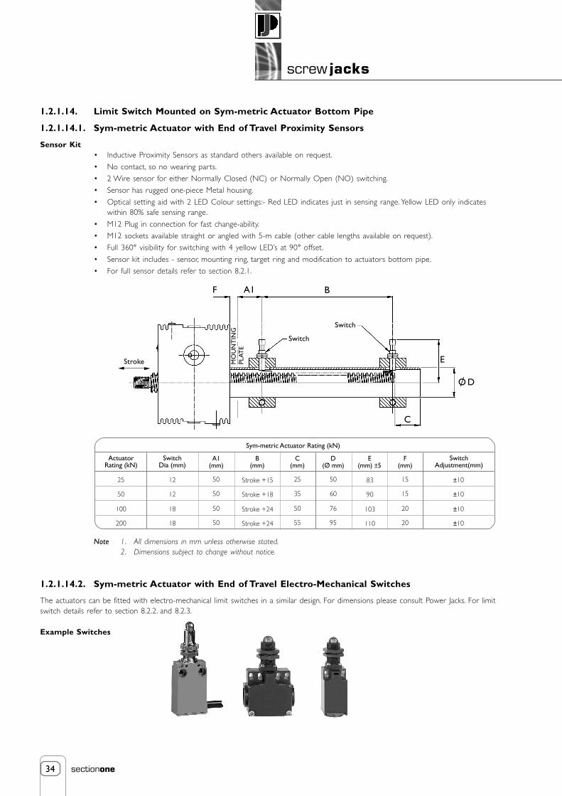
1.2.1.14. Limit Switch Mounted on Sym-metric Actuator Bottom Pipe
1.2.1.14.1. Sym-metric Actuator with End of Travel Proximity Sensors
Sensor Kit• Inductive Proximity Sensors as standard others available on request.
• No contact, so no wearing parts.
• 2 Wire sensor for either Normally Closed (NC) or Normally Open (NO) switching.
• Sensor has rugged one-piece Metal housing.
• Optical setting aid with 2 LED Colour settings:- Red LED indicates just in sensing range. Yellow LED only indicateswithin 80% safe sensing range.
• M12 Plug in connection for fast change-ability.
• M12 sockets available straight or angled with 5-m cable (other cable lengths available on request).
• Full 360° visibility for switching with 4 yellow LED’s at 90° offset.
• Sensor kit includes - sensor, mounting ring, target ring and modification to actuators bottom pipe.
• For full sensor details refer to section 8.2.1.
Note 1. All dimensions in mm unless otherwise stated.2. Dimensions subject to change without notice.
1.2.1.14.2. Sym-metric Actuator with End of Travel Electro-Mechanical Switches
The actuators can be fitted with electro-mechanical limit switches in a similar design. For dimensions please consult Power Jacks. For limitswitch details refer to section 8.2.2. and 8.2.3.
Example Switches
F A1 B
Switch
Stroke E
C
O D/
MO
UN
TIN
GPL
ATE
ActuatorRating (kN)
Sym-metric Actuator Rating (kN)
A1(mm)
50
B(mm)
Stroke +15
C(mm)
2525
50 Stroke +18 3550
SwitchDia (mm)
12
12
SwitchAdjustment(mm)
±10
±10
D(Ø mm)
50
E(mm) ±5
83
F(mm)
15
60 90 15
50 Stroke +24 50100
50 Stroke +24 55200
18
18
±10
±10
76 103 20
95 110 20
Switch

35
screw jacks
sectionone
Lifting ScrewThreaded end as standard
and available with screw onclevis end or top plate.
Shell CapLocked in place by
set screws.
Load BearingsBearings, top and bottom to takeloads in tension or compression.
Worm GearAluminium bronze. Accurately
hobbed for greater gear contact.
WormAvailable with double
or single shaft extension.
Thrust Bearingsand Grease SealsAt each end of worm.5 & 10 kN modelsdo not have seals.
Bottom PipeProtects lifting screw threads.
HousingAluminium on 5 & 10 kN models,ductile iron on 25 kN through100 kN models, cast steel on200 kN through 1000 kN models.
1.2.2. E-Series Metric Machine Screw Jacks
Advantages
• Positive, Mechanical Positioning • Uniform, Lifting Speed
• Multiple Arrangements • Anti-Backlash Feature (optional)
Capacities from 5 kN to 1000 kNWorm Gear Ratios from 5:1 to 36:1
The Metric machine screw actuator range is produced in many standard models with a wide range of capabilities, there is a standardmodel for almost any requirement.
Operated manually or by motor units metric actuator models can be used singly, in tandem or in multiple arrangements (refer 1.1.3.2.9.).Since most capacities have a uniform lifting speed, added economy can be realised in raising unevenly distributed loads by operating thedifferent capacities in unison.
Most Metric machine screw actuator models with higher ratios are self-locking and will hold heavy loads in position indefinitely withoutcreep, in ideal conditions. They can be used to push, pull, apply pressure and as linear actuators. They are furnished with standard raisesin increments of 25 mm. Depending upon size and type of load, models are available with raises up to 6 metres.

36
screw jacks
sectionone
More Than 5000 Standard Combinations
Features• Precise Positioning - Can be controlled accurately for positioning within hundredths of a millimetre.
• Self-Locking - Will normally hold loads in position without creeping when using the higher ratio units, as long as theactuator unit is not subject to vibration or cyclic temperature variation. If self-locking is critical a brake motor orother restraining device should be considered.
• Uniform Lifting Speed - Since many models have the same gear ratios, various capacities can be used in the sameapplication to lift unevenly distributed loads with uniform speed.
• Quick, Sure Operation - Designed and built to be positive acting, for accurate response to motive power.
Options• Two Standard Gear Ratios
• Anti-Backlash Option - Reduces vertical backlash between the screw and the worm gear nut to a practicalminimum for smooth, precise operation and minimum wear.
• Keyed Option - Stops a translating screw from rotating when the screw ends are free.
• Secondary Guide Option - Increases lifting screw lateral rigidity aiding screw guidance and improved side loadresilience.
• Bellows Boot Option - Protects the screw from dust, dirt, moisture and corrosive contaminants.
Note Clockwise rotation of worm raises load on all models (refer to previous page) - counter clockwise available atextra charge.Unless a translating lifting screw is keyed, the top should be bolted to the lifting member to prevent the screwfrom rotating.Actuators are equipped with “Alemite” grease fittings.Recommended lubricants are listed in the installation and maintenance instructions.Actuators supplied complete with drive shaft keys.
Attachments
IEC and Nema C-Face flanges, motors, gear boxes, reducers and couplings available for single actuator drive or multiple actuatorarrangements (refer 4, 5, 6, 7 and 8).
Motion control components include motor drives, Motion Controllers with operator interfaces, encoders, limit switches, potentiometersand meters with LCD display (refer 8.).
Upright Screw Rotating Screw (Upright)Available in both upright
and inverted types
Inverted Screw Threaded
Clevis

37
screw jacks
sectionone
1.2.2.1. Performance of Standard Metric Actuators
* All metric machine screws have a trapezoidal thread form, single start as standard.† For loads of 25% to 100% of actuator capacity, torque requirements are approximately proportional to the load.
Metric Actuator Efficiencies
Standard Gear Ratio
Optional Gear Ratio
Note Efficiency values for standard grease lubricated worm gear box and lifting screw.
E2625 E2501 E1802 E1805 E1850E1810 E1820 E1830 E18100Actuator ModelGear Ratio
Actuator Static Efficiency
Actuator Dynamic Efficiency
20
0.107
0.160
20
0.130
0.194
24
0.115
0.167
24
0.117
0.172
32
0.079
0.120
24
0.132
0.190
24
0.116
0.169
32
0.084
0.128
36
0.079
0.123
12
0.131
0.178
E2625 E2501 E1802 E1805 E1850E1810 E1820 E1830 E18100Actuator ModelGear Ratio
Actuator Static Efficiency
Actuator Dynamic Efficiency
5
0.189
0.252
5
0.233
0.306
6
0.201
0.264
6
0.213
0.281
10 2/3
0.132
0.181
8
0.206
0.272
8
0.181
0.242
10 2/3
0.149
0.205
Diameter
Pitch
Standard
Optional
Standard
Optional
Standard
Optional
Standard
Optional
E2625
5
16 mm
3 mm
5:1
20:1
5 for3 mm
20 for3 mm0.25
0.12
2.5
1.1
1.03
0.073
Actuator Model
Capacity (kN)
Lifting Screw *
Worm Gear Ratios
Turn of worm forraise of lifting screw
Maximum Input Powerper Actuator (kW)
Start-Up Torqueat full load (Nm) †
Weight with base raise of 150mm (kg)
Weight for each additional 25mm raise (kg)
E2501
10
20 mm
5 mm
5:1
20:1
1 for1 mm
4 for1 mm
0.375
0.19
6.8
3.0
2.27
0.13
E1802
25
30 mm
6 mm
6:1
24:1
1 for1 mm
4 for1 mm
1.5
0.375
19.8
8.7
8.17
0.21
E1805
50
40 mm
9 mm
6:1
24:1
1 for1.5 mm
4 for1.5 mm
3
0.55
56.0
25.5
15.88
0.32
E1810
100
55 mm
12 mm
8:1
24:1
1 for1.5 mm
2 for1 mm
3.75
1.125
115.9
60.5
24.72
0.57
E1820
200
65 mm
12 mm
8:1
24:1
1 for1.5 mm
2 for1 mm
3.75
1.125
263.8
137
45
0.86
E1830
300
95 mm
16 mm
10 2/3
32:1
1 for1.5 mm
2 for1 mm
6
1.9
480
284
86
1.58
E1850
500
120 mm
16 mm
10 2/3
32:1
1 for1.5 mm
2 for1 mm
11.25
4.5
904
504
195
2.49
E18100
1000
160 mm
20 mm
12:1
36:1
3 for5 mm
9 for5 mm
18.5
8.25
2025
1119
553
4.31

38
screw jacks
sectionone
1.2.2.2. Standard Metric Translating Screw Actuators
Note All Dimensions in mm.
Plan View
Note 1. Closed Height of threaded end and top plate units is the same for upright or inverted models.2. Dimensions are subject to change without notice.3. LHS = Left Hand Side4. RHS = Right Hand Side
HA
CAA
B
D
F
G
E
B
BB
C1
A
NMW
X
J
K
X
L
P
OQ
R P
OR
N VT
MU
S
K
J
X
W
L
Q
STUV L
U
K
J
X
OQ
MWN
RP
Models: 2625 & 2501 Models: 1802 1805 18101820 1830 1850
Models: 18100
InvertedUpright
RHS
LHS
RHS
LHS
RHS
LHS
I

39
screw jacks
sectionone
1.2.2.3. Standard Translating Screw Ends
AB
CC1DEFGHIJKLMNOPQRSTUV
W
XAABB
A + 9
954016
26.726 ± 0.13
10M10 X 1.5
2012060
10h83 X 3 X 18
91105585
42.5----
23.82+ 0.076- 0.000
276464
E2625
E2624
5
Upright
InvertedModel
Capacity (kN)
E2501
E2500
10
E1802
E1801
25
E1805
E1804
50
E1810
E1809
100
E1820
E1819
200
E1830
E1829
300
E1850
E1849
500
E18100
E18099
1000
A + 9(A+10)
1254520
33.440 ± 0.13
10M12 X 1.75
2415075
14h85 X 5 X 25
111306510050----
31.75+ 0.076- 0.000
359078
A + 5
1455530
48.345 ± 0.13
13M20 X 2.5
3018090
16h85 X 5 X 25
13.51105580401656513550
43.26+ 0.025- 0.02527.5103.595.5
A - 5
1856540
60.360 ± 0.13
14M24 X 3
3523011519h8
6 X 6 X 32181507511557.52057517057.555.58
+ 0.050- 0.000
35138122
A + 3
200805573
60 ± 0.1316
M36 X 44028014025h8
8 X 7 X 40221909514572.52257518052.566
+ 0.060- 0.000
44146.5130.5
A - 1
265956589
85 ± 0.1320
M48 X 55530015028h8
8 X 7 X 4026210105150752751052157566
+ 0.070- 0.000
44195179
A + 15
32511595115
105 ± 0.1330
M72 X 46538019035h8
10 X 8 X 503926013019095365140295105
95.25+ 0.130- 0.000
56235235
A + 13
390150120141
120 ± 0.1332
M100 X 49046023040h8
12 X 8 X 5651300150200100535225435175135
+ 0.070- 0.000
66275275
A + 3
560260160194
150 ± 0.1340
M125 X 412558029045h8
14 X 9 X 7051620310510255530205210150
190.5+ 0.076- 0.000
88405405
Raise As Required
F
UprightInvertedUprightInverted
Model
ABCDEFGHIJKL
E2625
Ø65P.C.D. 45
Ø25218
Ø9Ø25563015
Ø1015115609540
Ø80P.C.D. 55
Ø302410
Ø11Ø30633618
Ø12201456512545
Ø100P.C.D. 70
Ø4031.512
Ø13.5Ø4079.54623
Ø16301708014555
Ø120P.C.D. 85
Ø5036.516
Ø18Ø5091.56030
Ø20352109018565
Ø150P.C.D. 110
Ø654220
Ø22Ø651206633
Ø224024512520080
Ø170P.C.D. 120
Ø755825
Ø26Ø751438040
Ø305031014026595
Ø240P.C.D. 170
Ø1106730
Ø33Ø11016712060
Ø4580365155325115
Ø280P.C.D. 215
Ø1509235
Ø33Ø15021715075
Ø60110440200390150
Ø380P.C.D. 290
Ø20012775
Ø51Ø200297210105Ø90140625325560260
E2501 E1802 E1805 E1810 E1820 E1830 E1850 E18100
M
N
BA
N
C
DE A
CT
UA
TOR
BA
SE
L
= =
KJ
IH
M
AC
TU
ATO
R B
ASE
G
Top Plate
Clevis End
Note1850 & 18100Models have6 bolt holeson the Top Plate
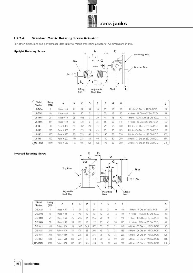
40
screw jacks
sectionone
1.2.2.4. Standard Metric Rotating Screw Actuator
For other dimensions and performance data refer to metric translating actuators. All dimensions in mm.
Upright Rotating Screw
Inverted Rotating Screw
Dia E
Pilot
B
LiftingNut
I
Shell D
Bottom Pipe
Mounting BaseF
G
A C
AdjustableShell Cap
C
Top Plate
E DA
G
H
B
Pilot
F Dia
AdjustableShell Cap
MountingBase
LiftingNut
KDia
Shell
IDia
HDia
JDia
UE-2626
UE-2502
UE-1803
UE-1806
UE-1811
UE-1821
UE-1831
UE-1851
UE-18101
ModelNumber
Rating(KN)
A B C D E F G H
5
10
25
50
100
200
300
500
1000
Raise + 40
Raise + 44
Raise + 60
Raise + 80
Raise + 100
Raise + 100
Raise + 180
Raise + 200
Raise + 250
16
16
25
30
50
65
85
100
125
64
90
103.5
138
146.5
195
235
275
405
34
0
0
0
28
24
40
63
128
10
12
20
25
35
45
75
90
125
25
35
40
65
75
75
140
150
175
10
12
15
20
25
25
35
50
60
60
80
90
115
160
185
230
280
380
I
4 Holes - 9 Dia. on 42 Dia. P.C.D.
4 Holes - 11 Dia. on 57 Dia. P.C.D.
4 Holes - 13.5 Dia. on 65 Dia. P.C.D.
4 Holes - 18 Dia. on 85 Dia. P.C.D.
4 Holes - 22 Dia. on 120 Dia. P.C.D.
4 Holes - 26 Dia. on 135 Dia. P.C.D.
6 Holes - 26 Dia. on 175 Dia. P.C.D.
6 Holes - 33 Dia. on 220 Dia. P.C.D.
6 Holes - 45 Dia. on 295 Dia. P.C.D.
J
25
35
40
55
80
90
125
160
210
DE-2626
DE-2502
DE-1803
DE-1806
DE-1811
DE-1821
DE-1831
DE-1851
DE-18101
ModelNumber
Rating(KN)
A B C D E F G H I
5
10
25
50
100
200
300
500
1000
Raise + 40
Raise + 44
Raise + 60
Raise + 80
Raise + 100
Raise + 100
Raise + 180
Raise + 200
Raise + 250
16
16
25
30
50
65
85
100
125
64
90
95.5
122
130.5
179
235
275
405
12
10
14
18
26.5
25
25
35
105
64
90
95.5
122
130.5
203
275
313
458
10
12
20
25
35
45
75
90
125
25
35
40
65
75
75
140
150
175
10
12
15
20
25
25
35
50
60
60
80
90
115
160
185
230
280
380
J
4 Holes - 9 Dia. on 42 Dia. P.C.D.
4 Holes - 11 Dia. on 57 Dia. P.C.D.
4 Holes - 13.5 Dia. on 65 Dia. P.C.D.
4 Holes - 18 Dia. on 85 Dia. P.C.D.
4 Holes - 22 Dia. on 120 Dia. P.C.D.
4 Holes - 26 Dia. on 135 Dia. P.C.D.
6 Holes - 26 Dia. on 175 Dia. P.C.D.
6 Holes - 33 Dia. on 220 Dia. P.C.D.
6 Holes - 45 Dia. on 295 Dia. P.C.D.
K
25
35
40
55
80
90
125
160
210
J

41
screw jacks
sectionone
Metric actuators are available with anti-backlash nuts for applications where a reversal of loadingfrom tension to compression is encountered.
Anti-Backlash Features
• Reduction in the vertical backlash between the screw and the worm gear nut to apractical minimum for smoother, more precise operation and minimum wear.
• Acts as a safety device, providing a dual nut load carrying unit, when the worm gearbecomes worn.
• Wear indicator for critical applications.
The anti-backlash feature can be maintained by adjusting the shell cap until the desired amount of backlash is achieved.To avoid binding and excessive wear, do not adjust lifting screw backlash to less than 0.013 mm (refer 1.5.2.1.1.7.).
Note Inverted unit closed height same as standard unit
Standard Dimensions (mm)
Torque and Efficiencies for Standard Anti-Backlash Actuators
Note 1. For loads from 25% to 100% of actuator capacity, torque requirements are proportional to the load.2. Dimensions are subject to change without notice.
Model
4625
4501
4802
4805
4810
4820
4830
4850
48100
Model
K4625
K4501
K4802
K4805
K4810
K4820
K4830
K4850
K48100
A
95
125
145
185
200
265
340
415
585
B
Anti-Backlash Keyed - Anti-Backlash
20
24
30
35
40
55
65
90
125
C
65
86
103.5
138
146.5
195
250
295
415
E
36
38
60
75
90
102
138
206
264
F G
25
30
37
40
48
58
73
95
180
H
20
24
30
35
40
55
65
90
125
I
40
45
55
65
80
110
115
213
405
J
14
16
19.5
24
30
39
43
63
145
D
Raise + 34
Raise + 35
Raise + 30
Raise - 5
Raise + 3
Raise + 24
Raise + 38
Raise + 55
Raise + 35
Raise + 9
Raise + 9
Raise + 5
Raise - 5
Raise + 3
Raise + 24
Raise + 15
Raise + 13
Raise + 3
4625
4624
5
2.9
1.3
0.164
0.090
1.48
Standard
Optional
Standard
Optional
Capacity (kN)
Start-Up Torque at Full Load (Nm)
Actuator Static Efficiency
Weight with Base Raise of 150mm (kg)approx.
4501
4500
10
7.8
3.7
0.203
0.109
2.72
4802
4801
25
23.5
9.8
0.169
0.102
8.62
4805
4804
50
62
28
0.192
0.105
16.78
4810
4809
100
129
67
0.185
0.119
26.12
4820
4819
200
281
153
0.170
0.104
48.6
4830
4829
300
535
314
0.134
0.076
90.5
4850
4849
500
1003
568
0.119
0.070
208.6
48100
48099
1000
2248
1245
0.118
0.071
609.8
ModelUpright
Inverted
1.2.2.5. Metric Actuators with Anti-Backlash Feature Shell Cap
B
CA
C
D
G
F
E E
H
JI
Upright
Upright
Inverted
Inverted
Anti-Backlash Keyed Anti-Backlash

41
screw jacks
sectionone
Metric actuators are available with anti-backlash nuts for applications where a reversal of loadingfrom tension to compression is encountered.
Anti-Backlash Features
• Reduction in the vertical backlash between the screw and the worm gear nut to apractical minimum for smoother, more precise operation and minimum wear.
• Acts as a safety device, providing a dual nut load carrying unit, when the worm gearbecomes worn.
• Wear indicator for critical applications.
The anti-backlash feature can be maintained by adjusting the shell cap until the desired amount of backlash is achieved.To avoid binding and excessive wear, do not adjust lifting screw backlash to less than 0.013 mm (refer 1.5.2.1.1.7.).
Note Inverted unit closed height same as standard unit
Standard Dimensions (mm)
Torque and Efficiencies for Standard Anti-Backlash Actuators
Note 1. For loads from 25% to 100% of actuator capacity, torque requirements are proportional to the load.2. Dimensions are subject to change without notice.
Model
E4625
E4501
E4802
E4805
E4810
E4820
E4830
E4850
E48100
Model
KE4625
KE4501
KE4802
KE4805
KE4810
KE4820
KE4830
KE4850
KE48100
A
95
125
145
185
200
265
340
415
585
B
Anti-Backlash Keyed - Anti-Backlash
20
24
30
35
40
55
65
90
125
C
65
86
103.5
138
146.5
195
250
295
415
E
36
38
60
75
90
102
138
206
264
F G
25
30
37
40
48
58
73
95
180
H
20
24
30
35
40
55
65
90
125
I
40
45
55
65
80
110
115
213
405
J
14
16
19.5
24
30
39
43
63
145
D
Raise + 34
Raise + 35
Raise + 30
Raise - 5
Raise + 3
Raise + 24
Raise + 38
Raise + 55
Raise + 35
Raise + 9
Raise + 9
Raise + 30
Raise + 20
Raise + 3
Raise + 24
Raise + 15
Raise + 13
Raise + 3
E4625
E4624
5
2.9
1.3
0.164
0.090
1.48
Standard
Optional
Standard
Optional
Capacity (kN)
Start-Up Torque at Full Load (Nm)
Actuator Static Efficiency
Weight with Base Raise of 150mm (kg)approx.
E4501
E4500
10
7.8
3.7
0.203
0.109
2.72
E4802
E4801
25
23.5
9.8
0.169
0.102
8.62
E4805
E4804
50
62
28
0.192
0.105
16.78
E4810
E4809
100
129
67
0.185
0.119
26.12
E4820
E4819
200
281
153
0.170
0.104
48.6
E4830
E4829
300
535
314
0.134
0.076
90.5
E4850
E4849
500
1003
568
0.119
0.070
208.6
E48100
E48099
1000
2248
1245
0.118
0.071
609.8
ModelUpright
Inverted
1.2.2.5. Metric Actuators with Anti-Backlash Feature Shell Cap
B
CA
C
D
G
F
E E
H
JI
Upright
Upright
Inverted
Inverted
Anti-Backlash Keyed Anti-Backlash

42
screw jacks
sectionone
1.2.2.6. Keyed Metric Actuators
A Keyed translating screw actuator stops the screw from rotating without the need for end pinning. However the key-way in the screwwill cause greater than normal wear on the internal threads of the worm gear.
Standard Keyed Dimensions for Inverted Models
1.2.2.7. Metric Actuators with Secondary Guide
Secondary Guiding for the screw for greater lateral rigidity aiding screw guidance and improved side load resilience.
Standard Secondary Guide Dimensions
** Consult Power Jacks Ltd
Note 1. All dimensions in mm.2. Dimensions are subject to change without notice.
Model E2624 E2500 E1801 E1804 E1809 E1819 E1829 E1849 E1899
A
B
C
Inverted
79
Raise
+ 9
35
78
Raise
+ 35
N/A
125.5
Raise
+ 30
60
159
Raise
+ 20
75
167.5
Raise
+ 3
90
210
Raise
- 1
102
267
Raise
+ 15
141.5
**
**
**
**
**
**
Model Capacity (kN) E2501E2625 E1802 E1805 E1810 E1820 E1830 E1850 E18100
A
B
C
D
E
F
Upright
Inverted
36
Raise +
34
16
36
Raise +
34
16
38
Raise +
34
20
**
Raise +
34
**
60
Raise +
30
20
60
Raise +
30
20
70
Raise +
20
18
70
Raise +
20
18
90
Raise +
29
20
90
Raise +
29
20
100
Raise +
24
20
100
Raise +
24
20
138
Raise +
40
38
138
Raise +
40
38
155
Raise +
38
38
155
Raise +
38
38
225
Raise +
50
65
**
**
**
B
Inverted
A
C
Upright
(dimensions asnon-keyed version
refer 1.2.2.2.)
InvertedUpright
C
B
D
E
F
A

43
screw jacks
sectionone
1.2.2.8. Metric Machine Screw Actuators with Bellows Boots
1.2.2.8.1. Bellows Boots for Metric Actuators
Features
• Protects the screw from dust and dirt.
• Guards against moisture and corrosive contaminants.
• Helps maintain the proper lubrication.
• Boots are made of P.V.C. coated nylon with sewn construction. Other materialsare available for applications involving high temperatures, highly corrosiveatmospheres and other special conditions.
1.2.2.8.1.1. Boot Dimensions
Note 1. F = Bellows boot minimum closed thickness.2. - = Not applicable.3. † = Control tapes fitted (approximately 20 mm increase to outer diameter).
E2625-B
E2501-B
E1802-B
E1805-B
E1810-B
E1820-B
E1830-B
E1850-B
E18100-B
A
25
30
40
50
65
75
110
150
200
B
60
70
90
115
136
165
220
285
220
C
100
110
120
140
150
165
191
210
244
D
13
15
15
15
15
20
20
20
20
E
13
15
23
31
31
20
20
45
20
Model
Raise 0 150
Raise 0 300
Raise 300 600
Raise 600 750
Raise 600 900
Raise 750 1000
Raise 600 1050
Raise 900 1050
Raise 1000 1250
Raise 1050 1500
Raise 1500 1800
Raise 1500 2000
Raise 1800 2100
Raise 2000 2500
Raise 2100 2500
Raise 2500 3000
20
30
-
-
-
-
-
-
-
-
-
-
-
-
-
E2625-B
10
Model E2501-B
-
E1802-B
-
E1805-B
-
E1810-B
-
E1820-B
-
E1830-B
-
E1850-B
-
E18100-B
-
F
20
35
40
-
60
-
-
60
-
-
-
-
-
-
-
20
30
-
-
-
50
-
-
70
100
-
-
-
-
-
20
30
-
45
-
-
50
-
70
95
-
110
-
130
160
20
30
-
-
-
50
-
-
70
-
105
-
120
-
-
20
30
-
-
-
50
-
-
70
90
-
110
-
-
-
20
30
-
-
-
50
-
-
70
100
-
-
-
-
-
20
30
-
-
-
50
-
-
70
-
-
-
-
-
-
20
30
-
-
-
50
-
-
70
-
-
-
-
-
-
D
F
E
B
C
A

44
screw jacks
sectionone
1.2.2.8.2. Bellows Boots for Metric Actuators
1.2.2.8.2.1. Standard Dimensions for all Upright Metric Actuators including Keyed
1.2.2.8.2.2. Standard Dimensions for all Upright Metric Anti-Backlash Actuators including Keyed
G G G+ H
Closed Heights
Threaded End Top Plate Clevis End
Raise 0 150
Raise 0 300
Raise 300 600
Raise 600 750
Raise 600 900
Raise 750 1000
Raise 600 1050
Raise 900 1050
Raise 1000 1250
Raise 1050 1500
Raise 1500 1800
Raise 1500 2000
Raise 1800 2100
Raise 2000 2500
Raise 2100 2500
Raise 2500 3000
Extra Closed Height for Clevis
110
120
-
-
-
-
-
-
-
-
-
-
-
-
-
20
E2625-B
100
Model E2501-B
-
E1802-B
-
E1805-B
-
E1810-B
-
E1820-B
-
E1830-B
-
E1850-B
-
E18100-B
-
G
H
140
155
160
-
180
-
-
180
-
-
-
-
-
-
-
20
160
170
-
-
-
190
-
-
210
240
-
-
-
-
-
25
200
210
-
225
-
-
230
-
250
275
-
290
-
310
340
25
215
225
-
-
-
245
-
-
265
-
300
-
315
-
-
45
280
290
-
-
-
310
-
-
330
350
-
370
-
-
-
45
330
340
-
-
-
360
-
-
380
410
-
-
-
-
-
40
390
400
-
-
-
420
-
-
440
-
-
-
-
-
-
50
560
565
-
-
-
585
-
-
605
-
-
-
-
-
-
65
115
120
-
-
-
-
-
-
-
-
-
-
-
-
-
20
E4625-B
105
E4501-B
-
E4802-B
-
E4805-B
-
E4810-B
-
E4820-B
-
E4830-B
-
E4850-B
-
E48100-B
-
140
155
160
-
180
-
-
180
-
-
-
-
-
-
-
20
160
170
-
-
-
190
-
-
210
240
-
-
-
-
-
25
200
210
-
225
-
-
230
-
250
275
-
290
-
310
340
25
215
225
-
-
-
245
-
-
265
-
300
-
315
-
-
45
280
290
-
-
-
310
-
-
330
350
-
370
-
-
-
45
345
355
-
-
-
375
-
-
395
425
-
-
-
-
-
40
415
425
-
-
-
445
-
-
465
-
-
-
-
-
-
50
585
585
-
-
-
600
-
-
620
-
-
-
-
-
-
65
Raise 0 150
Raise 0 300
Raise 300 600
Raise 600 750
Raise 600 900
Raise 750 1000
Raise 600 1050
Raise 900 1050
Raise 1000 1250
Raise 1050 1500
Raise 1500 1800
Raise 1500 2000
Raise 1800 2100
Raise 2000 2500
Raise 2100 2500
Raise 2500 3000
Extra Closed Height for Clevis
Model
G
H

45
screw jacks
sectionone
1.2.2.8.3. Inverted Metric Actuators with Bellows Boots
Applies to all inverted Metric actuators including Anti-Backlash and Keyed.
1.2.2.8.4. Notes for all Metric Actuators with Bellows Boots
Note 1. Supplied complete with a set of corrosion-resistant 'jubilee' clips (2) suitable for fitting over collar diameters.2. † Control tapes are fitted (approximately 20 mm increase to outer diameter).3. For horizontal installation exceeding 450 mm of travel, internal boot guides are recommended.4. Customers with threaded end actuators must provide a fixing for the unattached collar (★ ).5. Bellows boots for Rotating Screw Actuators consult Power Jacks Ltd.6. For other sizes, raises, and materials please consult Power Jacks Ltd.7. All dimensions in millimetres unless otherwise stated.8. Dimensions subject to change without notice.
Mounting Plate
Raise 0 150
Raise 0 300
Raise 300 600
Raise 600 750
Raise 600 900
Raise 750 1000
Raise 600 1050
Raise 900 1050
Raise 1000 1250
Raise 1050 1500
Raise 1500 1800
Raise 1500 2000
Raise 1800 2100
Raise 2000 2500
Raise 2100 2500
Raise 2500 3000
Extra Closed Height for Clevis
Extra Closed Height forKeyed Anti-Backlash Units
70
80
90
-
-
-
-
-
-
-
-
-
-
-
-
-
20
4
E2624-B
10
Model E2500-B
10
E1801-B
15
E1804-B
15
E1809-B
20
E1819-B
20
E1829-B
30
E1849-B
30
E18099-B
50
K
M
L
P
-
85
100
105
-
125
-
-
125
-
-
-
-
-
-
-
20
6
-
105
115
-
-
-
135
-
-
155
185
-
-
-
-
-
25
4.5
-
120
130
-
145
-
-
150
-
170
195
-
210
-
230
260
25
9
-
130
140
-
-
-
160
-
-
180
-
215
-
230
-
-
45
10
-
135
145
-
-
-
165
-
-
185
205
-
225
-
-
-
45
19
-
165
175
-
-
-
195
-
-
215
245
-
-
-
-
-
40
13
-
215
225
-
-
-
245
-
-
265
-
-
-
-
-
-
50
33
-
260
260
-
-
-
280
-
-
300
-
-
-
-
-
-
65
115
★
K
ClosedHeights
K
Actuator Mounting Plate,‘M’ thick. Alter thicknessto suit application.
K+L
Boot Mounting Plate,to suit collar size.Typically
ØB x (E+5 mm fittingallowance) thick.

46
screw jacks
sectionone
1.2.2.9. Standard Flange Bolt Configuration for Worm Shafts
1.2.2.10. Metric Double Clevis End Actuators
Note For other performance and dimension information refer to translating screw models.
Note 1. All dimensions in millimetres unless otherwise stated.2. Dimensions subject to change without notice.
Model
E2625
E2501
E1802
E1805
E1810
E1820
E1830
E1850
E18100
'B' Bolt P.C.D. (mm)
N/A
N/A
46
61
70
88
107
135
160
Bolt Information
N/A
N/A
M6 X 1 mm Pitch, 14 mm Deep
M8 X 1.25 mm Pitch, 22 mm Deep
M8 X 1.25 mm Pitch, 14 mm Deep
M10 X 1.5 mm Pitch, 14 mm Deep
M10 X 1.5 mm Pitch, 19 mm Deep
M16 X 2 mm Pitch, 25 mm Deep
M16 X 2 mm Pitch, 28 mm Deep
Configuration
N/A
N/A
A
A
A
A
A
A
B
5
1
150
115
35
15
26.7
15
10
220
CCE2625
CCE2501
CCE1802
CCE1805
CCE1810
CCE1820
CCE1830
CCE1850
A
B
C
D
E
F
G
Capacity (kN)
Style
Model
Max Raise at Rated Load(Compression)
10
1
180
145
35
20
33.4
20
12
175
25
2
213
170
43
23
48.3
30
16
352
50
2
260
210
50
30
60.3
35
20
420
100
2
352
247
105
33
73
40
22
593
200
2
428
313
115
40
102
50
30
592
300
2
492
367
125
60
141
80
45
1338
500
2
570
440
130
75
168
110
60
1920
B BConfiguration A Configuration B
Style 1 Style 2
GF
Raise Raise + CRaise + A
B
Standard Clevis
DD
E
45o
45o
60o
60o

47
screw jacks
sectionone
1.2.2.11. Motor Adaptors for Metric Actuators
• Standard adaptors for 25 kN - 300 kN metric machine screw and ball screw actuators.
• Designed for standard IEC frame sizes.
• Allows direct motor coupling on either side of the actuator input shaft.
• Complete with drive coupling and mounting hardware.
• NEMA frame size versions available on request.
• Adaptors for other Metric actuators and mounting arrangements available on request.
• Adaptors for Imperial actuators available on request.
Note When direct coupling a motor to an actuator, it is necessary to match motor power to actuator load so the motordoes not exceed the maximum actuator power.
Motor Adaptors
Std.Part
✔
✗
✔
✔
✔
✔
✔
✔
✗
✗
✗
✗
A
25 50 100
Actuator Rating (kN)
200 300
145
-
160
145
160
145
160
160
-
-
-
-
B
14
-
14
14
14
14
14
14
-
-
-
-
C(squ.)
80
-
80
80
80
80
80
80
-
-
-
-
StdPart
✗
✗
✔
✗
✔
✗
✔
✔
✔
✔
✔
✔
A
-
-
187
-
187
-
207
187
207
187
207
207
B
-
-
14
-
14
-
14
14
14
14
14
14
C(squ.)
-
-
100
-
100
-
100
100
100
100
100
100
A
-
-
-
-
250
260
280
260
280
260
280
280
B
-
-
-
-
14
14
14
14
14
14
14
14
C(squ.)
-
-
-
-
120
120
120
120
120
120
120
120
StdPart
✗
✗
✗
✗
✔
✔
✔
✔
✔
✔
✗
✔
A
-
-
-
-
212
212
212
212
212
212
-
232
-
-
-
-
212
212
212
212
212
212
-
232
B
-
-
-
-
14
14
14
14
14
14
-
14
C
-
-
-
-
110
110
110
110
110
110
-
110
D
-
-
-
-
98
98
98
98
98
98
-
98
-
-
-
-
14
14
14
14
14
14
-
14
-
-
-
-
110
110
110
110
110
110
-
110
-
-
-
-
98
98
98
98
98
98
-
98
Std.Part
✗
✗
✗
✗
✔
✔
✔
✔
✔
✔
✗
✔
Std.Part
✗
✗
✗
✗
✔
✔
✔
✔
✔
✔
✔
✔
B5
B14 C105
B5
B14 C120
B5
B14 C140
B5
B14 C160
B5
B14 C190
B5
B14 C200
MotorMounting
71
80
90
100
112
132
FrameSize
A B C D
A
C
B
D
Motor

48
screw jacks
sectionone
1.2.2.12. Trunnion Mounts for Metric Actuators
Trunnion mounts bolt onto actuator base plates.
Note: 1. Trunnion mounts for other actuator sizes are available on request.2. All dimensions in millimetres (mm) unless otherwise stated.3. Dimensions subject to change without notice.
Example diagram ofactuator with trunnion mount fitted
Actuator Rating(kN)
5
10
25
50
100
A
114
175
160
200
270
B
114
135
120
160
200
C
57
67.5
60
80
100
D
60
80
165
205
225
E
-
-
135
170
180
F
30
40
50
57.5
52.5
G
110
130
110
150
190
H
85
100
80
115
145
J (h6)
15
20
25
35
45
K
20
25
30
40
50
L
10
12.5
15
20
25
M
50
58
72
95
130
N
M8 (2)
M10 (2)
M12 (4)
M16 (4)
M20(4)
Weight(kG)
1.24
2.27
3.27
8.90
15.57
GH
N
Ø J
CBA
ØMK
FD
L
CØMN
E
F
GH
BA
L
Ø JD
K
5 & 10 kN Models 25, 50 & 100 kN Models

49
screw jacks
sectionone
Rotary limit switches can be used as end of travel limit switcheswith the option of intermediate switches as well. These units aremounted onto a screw jacks free worm shaft and offer analternative where bottom pipe mounted limit switches are notpossible e.g. rotating screw jacks. Up to 8 limit switches can beaccommodated in one unit.
For full details on the RLS-51 limit switch refer to section 8.1.1.
The mounting kit includes the flexible coupling and driveadaptor.
Note 1. All dimensions are in millimetres (mm) unlessotherwise stated.
2. Dimensions are subject to change without notice.
1.2.2.13. RLS-51 Rotary Limit Switch Adaptors for Metric Actuators
AdaptorMounting
Metric Actuator Rating (kN)
StdPart
✗
A
-
B
-
C(squ)
-B5
StdPart
✗
A
-
B
-
C(squ)
-
✔ 117 10 70B14 ✔ 133 10 89
AdaptorMounting
Metric Actuator Rating (kN)
StdPart
✔
A
152
B
13
C(squ)
98B5
StdPart
✔
A
174
B
13
25 50
100 200
C(squ)
125
✗ - - -B14 ✗ - - -
1.2.1.14. SKA Rotary Limit Switch Adaptors for Metric Actuators
The SKA rotary limit switch is a compact 2-position limit switch designed for screw jack and linear actuator applications. For full detailson the SKA limit switch refer to section 8.1.2.
Note 1. All dimensions are in millimetres (mm) unless otherwise stated.2. Dimensions are subject to change without notice.
A* Ref
ØC
B
76 mm
1/2” NPT
90.5 mm
168 mm
159 mm
Actuator Mounted

50
screw jacks
sectionone
1.2.2.14.1. Mounting and Adjustment Specifications for SKA Rotary Limit Switches
Typical top view showing switchmounted on RH worm extensionPosition Number of Switch
1000 kN metric; 75, 100 & 150 TonsImperial models only
2
1 3
4
2
1
3
4
CClosed
Mount (mm)
-
163.5
179.2
195
222.5
252
290
BExtended
Mount (mm)
172.5
198.5
223.4
233.5
273.5
313
373.5
ACut-off ClosedMount (mm)
-
35
44.2
38.5
51
61
83.5
Model(kN)
25
50
100
200
300
500
1000
DWorm ShaftDia. (mm)
16
19
25
28
35
40
45
A4mm
(0.157”)4mm
(0.157”)
Drill 7.9mm (5/16”) Diax 9.5 mm (3/8”) Deep
D
Drill 2.38mm (3/32”) DiaThro’ for Spring Pin
BC
- Extended Mount
- Closed Mount
Spacers as requiredExtended Mount only
Adaptor Plate
Optional Remote ScrewPosition Analog Indicator Standard 1/2” x 14 TPI
Note: Shim out on limit switch if necessary worm shaft end must not rub switch housing.Dimensions subject to change without notice.
Note 1. All dimensions are in millimetres (mm) unlessotherwise stated.
2. Dimensions are subject to change without notice.
Capacity(kN)
Actuator
25
50
100
200
300
500
1000
1
C
2
A & B
A
A
A
3
RH LH RH
Extended Mount Closed Mount
LH
B & D
D
D
4
C
C
C
C
C
C
C
C
C
C
C
C
C
1 2 3 4 1
-
-
-
2
-
A & B
A & B
A & B
B
-
3
-
D
D
4
-
-
-
-
-
-
1
-
D
D
-
2
-
A & B
A & B
A & B
A & B
B
-
3
-
4
-
-
-
-
-
-
✔
✔
✔
✔
✔
✔
✔
✔
✔
✔
✔
✔
✔
✔
C
✔
✔
✔
✔
✔ ✔
✔
✔
✔
✔
✔
✔
✔ ✔
✔ ✔ ✔ ✔
✔
✔
✔
✔
B & D
D
D
✔
✔
✔
✔✔
✔
✔
✔
A & B
A
A
A
✔
✔
✔
1.2.2.15. Encoder Adaptors for Metric Machine Screw Actuators
Both incremental and absolute encoders can be mounted on a Metric actuators free worm shaft. The specification for these encoders isgiven in section 8.3. For mounting details please consult Power Jacks Ltd.
Note (A) Special Closed Height. (B) Boot Interference Unit. (C) Rotary Limit Switch extends below base of Actuator Unit.(D) Sealed electric elbow would extend below base of Actuator Unit. (✓ ) Recommended. ( - ) Not RecommendedExtended Mount is Standard.
1.2.2.14.2. SKA Limit Switch Field Installation Dimensions
C Lifting ScrewL

51
screw jacks
sectionone
1.2.2.16. Limit Switches Mounted on Metric Actuator Bottom Pipe
1.2.2.16.1. Metric Actuator with End of Travel Proximity Sensors
Sensor Kit• Inductive Proximity Sensors as standard other available on request.
• No contact, so no wearing parts.
• 2 Wire sensor for either Normally Closed (NC) or Normally Open (NO) switching.
• Sensor has rugged one-piece Metal housing.
• Optical setting aid with 2 LED Colour settings:- Red LED indicates just in sensing range. Yellow LED only indicateswithin 80% safe sensing range.
• M12 Plug in connection for fast change-ability.
• M12 sockets available straight or angled with 5-m cable (other cable lengths available on request).
• Full 360° visibility for switching with 4 yellow LED’s at 90° offset.
• Sensor kit includes - sensor, mounting ring, target ring and modification to actuators bottom pipe.
• For full sensor details refer to section 8.2.1.
Note 1. All dimensions in mm unless otherwise stated.2. Dimensions subject to change without notice.3. Other metric actuator sizes are available with bottom pipe limit switches. Consult Power Jacks Ltd for advice.
1.2.2.16.2. Metric Actuator with End ofTravel Electro-Mechanical Switches
The actuators can be fitted with electro-mechanical limit switches in a similardesign. For dimensions please consult Power Jacks Ltd. For limit switch detailsrefer to section 8.2.2. and 8.2.3.
F
A2B
Switch
Stroke
E
C
O D/
MO
UN
TIN
GPL
ATE
Switch
ActuatorRating (kN)
Metric Upright & Inverted Actuators
A1(mm)
50
B(mm)
Stroke +15
C(mm)
4025
50 Stroke +18 4050
SwitchDia (mm)
12
12
SwitchAdjustment (mm)
±10
±10
D(Ø mm)
48
E(mm) ±5
83
F(mm)
15
60 90 15
50 Stroke +24 45100
50 Stroke +24 45200
18
18
±10
±10
73 103 20
89 110
A2(mm)
40
40
40
40 20
Stroke
C A1 B
E
O D/
SwitchSwitch

52
screw jacks
sectionone
1.2.2.17. Metric Machine Screw Actuators with Safety NutsPower Jacks metric machine screw actuators can be fitted with a safety nut, which provides 2 safety roles:
1. In the event of excessive wear on the nut thread the load will be transferred from the standard nut to the safetynut. This will also provide visual wear indication as the gap between the safety nut decreases to zero as the standardlifting nut wears.
2. In the unlikely event of catostrophic nut thread failure the safety nut will sustain the load. The safety of industrial andhuman cargo is therefore improved.
There are several configurations for each safety nut device as they only work in one load direction. For this reason when orderingplease supply a sketch of your application showing load directions.
1.2.2.18. Translating Metric Actuators with Safety NutsTranslating Metric Actuators with safety nuts are similar in format to the anti-backlash units. Consult Power Jacks for details.
1.2.2.19. Rotating Metric Actuators with Safety Nuts
UE-1803
UE-1806
UE-1811
UE-1821
ModelNumber
Rating(KN)
A B C D E F
25
50
100
200
Raise + 95
Raise + 140
Raise + 170
Raise + 170
33.5
58
67
67
75
125
145
145
15
20
25
25
90
115
160
185
40
55
80
90
G
4 Holes - 13.5 Dia. on 65 Dia. P.C.D.
4 Holes - 18 Dia. on 85 Dia. P.C.D.
4 Holes - 22 Dia. on 120 Dia. P.C.D.
4 Holes - 26 Dia. on 135 Dia. P.C.D.
DE-1803
DE-1806
DE-1811
DE-1821
ModelNumber
Rating(KN)
A B C D E F
25
50
100
200
Raise + 95
Raise + 140
Raise + 170
Raise + 170
33.5
58
67
67
75
125
145
145
15
20
25
25
90
115
160
185
40
55
80
90
G
4 Holes - 13.5 Dia. on 65 Dia. P.C.D.
4 Holes - 18 Dia. on 85 Dia. P.C.D.
4 Holes - 22 Dia. on 120 Dia. P.C.D.
4 Holes - 26 Dia. on 135 Dia. P.C.D.
A
C
B D
G
ØF
ØE
A
C
BD
G
ØFØE
A
C
BD
G
ØFØE
A
C
B D
G
ØFØE
Load
Load
Load
Load
Upright Models Inverted Models
Upright Rotating Screw
Inverted Rotating Screw
Note: 1. All dimensions in millimetres. 2. Dimensions subject to change without notice.

53
screw jacks
sectionone
1.2.3. M-Series Imperial Machine Screw Jack Models
Advantages
• Positive, Mechanical Positioning
• Uniform, Lifting Speed
• Multiple Arrangements
• Anti-Backlash Feature (optional)
Capacities from 1/4 Ton to 250 TonWorm Gear Ratios from 5:1 to 50:1
The imperial machine screw actuator range is produced in many standard models with a wide range of capabilities, there is a standardmodel for almost any requirement.
Operated manually or by motor units imperial actuator models can be used singly, in tandem or in multiple arrangements (refer1.1.5.2.9.). Since most capacities have a uniform lifting speed, added economy can be realised in raising unevenly distributed loads byoperating the different capacities in unison.
Most imperial machine screw actuator models with higher ratios are self-locking and will hold heavy loads in position indefinitely withoutcreep, in ideal conditions. However if self-locking is critical, a brake motor or other restraining device should be considered. They can beused to push, pull, apply pressure and as linear actuators. They are furnished with standard raises in increments of 1 inch. Dependingupon size and type of load, models are available with raises up to 25 feet.
Bottom Pipe Protects liftingscrew threads.
Shell CapLocked in place by set screws.
Lifting ScrewAvailable with threaded end orclevis end instead of top plate.
Load BearingsBearings, top and bottom
to take loads in tension orcompression.
Worm GearAluminium bronze.
Accurately hobbed for greater gear contact.
WormAvailable with double
or single shaft extension.
Thrust Bearingsand Grease SealsAt each end of worm.1/4 & 1/2 ton modelsdo not have seals.
Housing Aluminium on 1/4 to 1 ton models,ductile iron on 2 ton through15 ton models, cast steel on20 ton through 250 ton models.
Top PlateMust be bolted to lifting member to preventy rotation except when screw is keyed.

54
screw jacks
sectionone
More Than 200 Standard Combinations
Features• Precise Positioning - Can be controlled accurately for positioning within thousandths of a millimetre.
• Self-Locking - Will normally hold loads in position without creeping when using the higher ratio units, as long as theactuator unit is not subject to vibration. If self-locking is critical a brake motor or other restraining device should beconsidered.
• Uniform Lifting Speed - Since many models have the same gear ratios, various capacities can be used in the sameapplication to lift unevenly distributed loads with uniform speed.
• Quick, Sure Operation - Designed and built to be positive acting, for accurate response to motive power.
Options• Anti-Backlash Option - Reduces vertical backlash between the screw and the worm gear nut to a practical
minimum for smooth, precise operation and minimum wear.
• Keyed Option - Stops a translating screw from rotating when the screw ends are free.
• Bellows Boot Option - Protects the screw from dust, dirt, moisture and corrosive contaminants.
• Double Clevis End Option - Incorporates a special clevis end bottom pipe and a standard clevis end on thelifting screw.
Note Clockwise rotation of worm raises load on all models (refer to previous page) - counter clockwise available atextra charge.Unless a translating lifting screw is keyed, the top should be bolted to the lifting member to prevent the screwfrom rotating.Actuators are equipped with “Alemite” grease fittings.Recommended lubricants are listed in the installation and maintenance instructions.Actuators supplied complete with drive shaft keys.
Attachments
Nema C-Face flanges, motors, gear boxes, reducers and couplings available for single actuator drive or multiple actuator arrangements(refer 4, 5, 6, 7 and 8).
Motion control components include motor drives, Motion Controllers with operator interfaces, encoders, limit switches, potentiometersand meters with LCD display (refer 8.).
Upright Screw Rotating Screw (Upright)Available in both upright
and inverted types
Inverted ScrewThreaded
Clevis

55
screw jacks
sectionone
Imperial Actuators with Numeric Control Ratios
1 to 25 Ton Actuators with Decimal Ratio at no extra cost.
Numeric Control Ratios 100 Turns = 1” of Travel
Note: 1. All other data for these models is the same as main performance table at the top of the page.2. For loads from 25% to 100% of actuator capacity, torque requirements are approximately proportional
to the load.
2501
2500
1
0.75
0.2
Acme
5:1
20:1
25
100
0.5
0.25
55
25
0.245
0.140
5
0.27
1802 &9002
1801 &9001
2
1
0.25
Acme
6:1
24:1
24
96
2
0.5
120
50
0.232
0.133
17
0.33
2555
2554
0.25
0.5
0.25
Acme
5:1
-
20
-
0.333
-
13
-
0.330
-
2.33
0.1
Upright
Inverted
Diameter
Pitch
Form
Standard
Optional
Standard
Optional
Standard
Optional
Standard
Optional
Standard
Optional
Capacity (Short Tons)
Model
Start-UpTorque at Full Load (in.lb)
ActuatorEfficiency
2625
2624
0.5
0.625
0.125
Acme
5:1
-
40
-
0.333
-
21
-
0.200
-
2.33
0.1
1815
1814
15
2.25
0.5
Square
8:1
24:1
16
48
5
1.5
1430
820
0.202
0.129
66
1.5
1805
1804
5
1.5
0.375
Square
6:1
24:1
16
64
4
0.75
450
185
0.221
0.121
35
0.85
1810
1809
10
2
0.5
Square
8:1
24:1
16
48
5
1.5
950
490
0.220
0.140
52
1.4
1825
1824
25
3.375
0.666
Square
10 2/3:1
32:1
16
48
8
2.5
3360
1900
0.164
0.092
181
3.5
1820
1819
20
2.5
0.5
Square
8:1
24:1
16
48
5
1.5
2050
1170
0.188
0.120
93
2.6
1850
1849
50
4.5
0.666
Square
10 2/3:1
32:1
16
48
15
6
7500
4200
0.138
0.083
410
5.5
9035
9034
35
3.75
0.666
Acme
10 2/3:1
32:1
16
48
8
2.5
4000
2400
0.158
0.089
240
3.7
9075
9074
75
5
0.666
Square
10 2/3:1
32:1
16
48
15
6
12000
6600
0.124
0.075
650
6.5
1899
1898
100
6
0.75
Square
12:1
36:1
16
48
25
11
16000
8600
0.130
0.080
1200
9
18150
18149
150
7
1
Square
12:1
36:1
12
36
25
11
28100
15500
0.141
0.086
1350
12.6
2250
2249
250
9
1
Square
50:1
-
50
-
35
-
20000
-
0.080
-
2700
23
Lifting Screw
Worm GearRatios
Turns of Worm for1" Raise
Max. HP perActuator
Weight with BaseRaise of 6" (lb)
Weight for eachAdditional 1" Raise (lb)
Capacity (Short Tons)
Worm Gear Ratios
Turns of Worm for 1" Raise
Start-Up Torque at Full Load (in.lb)
Actuator Efficiency
Maximum HP per Actuator
Upright
Inverted
Diameter
Pitch
Form
Model 2501
2500
1
0.75
0.200
Acme
20:1
100
24
0.133
0.25
1805
1804
5
1.5
0.250
Acme
25:1
100
175
0.091
0.75
1810
1809
10
2
0.250
Acme
25:1
100
370
0.086
1.5
1815
1814
15
2.25
0.250
Acme
25:1
100
640
0.075
1.5
1820
1819
20
2.5
0.250
Acme
25:1
100
925
0.069
1.5
1825
1824
25
3
0.320
Acme
32:1
100
1500
0.053
2.5
1802 & 9002
1801 & 9001
2
1
0.250
Acme
25:1
100
48
0.132
0.5
Lifting Screw
1.2.3.1. Performance of Standard M-Series Imperial Machine Screw Jacks
Note For loads from 25% to 100% of actuator capacity, torque requirements are approximately proportional to the load.
Raises, measured in increments of one inch, are available up to 20 feet, depending on lifting screw diameter and available bar stocklength.

56
screw jacks
sectionone
Not
e1.
All d
imen
sions
in in
ches
.2.
Dim
ensio
ns s
ubje
ct t
o ch
ange
with
out
notic
e.
Upr
ight
A
Inve
rted
CA
A
B
D E
GF
I
HE D
B BB C AH
ISt
y le
2St
y le
3
ST
U VN
O
PR
Q
ZW
XK
J
LM
ST
U
VN
O
PR
Q
Z
W
XK
J
L
M
Styl
e 1
N
O
PR
Q
ZW
XK
J
LM
YY
X
Y
Styl
e 4S
TU
VN
O
PR
Q
ZW
XK
J
M
Y
LU
ST
X
VN
O
PR
Q
Z
W
X
K
J
M
Y
L
U
Styl
e 5
1.2.2.3. Standard/Imperial Translating Screw Actuators
RHS
LHS
RHS
LHS
RHS
LHS
RHS
LHS
RHS
LHS
3.LH
S =
Lef
t H
and
Side
4.RH
S =
Rig
ht H
and
Side

57
screw jacks
sectionone
Mod
el
Styl
eA B C D E F G H I J K L M N O P Q R S T U V W X Y Z A-A B-B
2555
2554
0.25 1 0.5 1
5 /16
21/4
5 /16
41/2
21/4
9 /32 4 2 31/4
15/8
11/8
1.5
9 /32 4 23/8
23/8
2625
2624
0.5 1
0.62
5
15 /
16
21/4
5 /16
41/2
21/4
9 /32 4 2 31/4
15/8
11/8
1.5
9 /32 4 23/8
23/8
2501
2500 1 1
0.75 1.5
3 /8
31/2
3 /8 6 3
13/3
2
5 21/2 4 2
17/1
6
2.5
7 /16 4 31/4
31/4
1802
1801 2 2 1
1.75 1 /2
41/4
7 /16 7 3.5
13/3
2
7 3.5 6 3 31/2
13/4 2 1 11/8 3
13/3
2
441
/16
33/4
9002
9001 2 3 1
1.75 1 /2
41/4
7 /16 7 3.5
13/3
2
41/8
21/1
6
31/8
19/1
6
61/4
2.42
51/4
1.93
11/8 3
13/3
2
441
/16
33/4
1805
1804 5 3 1.5
2.25 1 /2
41/2
5 /8 9 4.5
11/1
6
6 3 41/2
21/4 8 3 61/2
2.25
111 /
32
311
/16
4 51/4
43/4
1810
1809 10 3 2
2.25 1 /2
53/4
3 /4
11 5.5
13/1
6
7.5
33/4
53/4
27/8
83/4
27/8 7 2
123 /
32
4.13
13/1
6
4 55/8 5
1815
1814 15 3
2.25
2.75 5 /8
53/4
3 /4
11 5.5
13/1
673
/437
/8 6 3 91/4
33/8
71/2
2.5
123 /
32
4.13
13/1
6
465
/16
51/2
1820
1819 20 3 2.5
3.25 3 /4
53/4
3 /4
11 5.5
11/8
81/4
41/8 6 3 11 41/8
83/4 3 13/8
4.13
13/1
6
4 71/8
71/8
1825
1824 25 3
3.37
5
4 1 81/2 1 14 7 13/8
101 /
4
51/8
71/2
33/4
133 /
4
51/8
11 3.75
23/1
6
611
/16
4 87/8
87/8
9035
9034 35 3
3.75 4 11/4
101 /
2
15/1
6
14 7 15/8
10.2
551
/871
/233
/415
1 /2
612
.54.
5
23/1
6
7.75
15/8 4 87/8
87/8
1850
1849 50 2 4.5
4.75
11/4
111 /
4
11/4
22 11 17/8
193 /
4
97/8
16 8 93/4
47/8 6 3
45/1
6
8.75
13/8 4
107 /
8
107 /
8
9075
9074 75 2 5 5.5
13/8
111 /
4
13/8
24 12 21/8
14 7 10 5 23 9.5
19 7.5
41/8
10.2
51.
5 613
9 /16
139 /
16
1899
1898
100 4 6 6 11/2
1421
5 /16
23 11.5
17/8
241 /
2
121 /
4
20 10 203 /
4
8 81/8
5.75
37/1
6
11 17/8 6 17 17
1815
018
149
150 4 7 6 11/2
1421
5 /16
23 11.5
17/8
24.5
121 /
4
20 10 203 /
4
8 81/8
5.75
41/4
11 17/8 6 17 17
2250
2249
250 5 9 9 21/2
2431
5 /16
48 24 23/4
41 201 /
2
35 17.5
291 /
2
14.7
520
1 /2
11 101 /
2
16 23/4 6
231 /
8
231 /
8
Upr
ight
Inve
rted
RA
ISE
DIA
.
DIA
.
DIA
.
DIA
.
P.C.D
DIA
.N
o. o
f Hol
es
Cap
acity
(Sh
ort T
ons)
A+
3 /4
A+
3 /4
7 /8
7 /8
15/1
612
1 /32
121 /
3223
/827
/827
/831
/241
/241
/259
/16
65/8
78
11
0.37
5+
0.00
0-0
.002
0.37
5+
0.00
0-0
.002
0.50
0+
0.00
0-0
.002
0.50
0+
0.00
0-0
.002
0.50
0+
0.00
0-0
.002
0.75
+0.
000
-0.0
02
1+
0.00
0-0
.002
1+
0.00
0-0
.002
1+
0.00
0-0
.002
1.37
5+
0.00
0-0
.002
1.37
5+
0.00
0-0
.002
1.5
+0.
000
-0.0
02
1.75
+0.
000
-0.0
02
1.75
+0.
000
-0.0
02
1.87
5+
0.00
0-0
.002
3+
0.00
0-0
.002
0.93
8+
0.00
3-0
.000
0.93
8+
0.00
3-0
.000
1.25
+0.
003
-0.0
03
1.70
3+
0.00
1-0
.001
1.70
3+
0.00
1-0
.001
2.18
8+
0.00
2-0
.000
2.59
8+
0.00
3-0
.000
2.59
8+
0.00
3-0
.000
2.59
8+
0.00
3-0
.000
3.75
+0.
005
-0.0
00
3.75
+0.
005
-0.0
00
5.31
3+
0.00
3-0
.000
5.31
3+
0.00
3-0
.000
7.5
+0.
003
-0.0
00
7.5
+0.
003
-0.0
00
13+
0.00
5-0
.000
1 /8
x 1 /
163 /
4 LN
G1 /
8 x
1 /16
3 /4
LNG
1 /8
x 1 /
16 1
LN
G1 /
8 x
1 /16
1 L
NG
1 /8
x 1 /
16 1
LN
G3 /
16 x
3/3
2 1
1 /4
LNG
1 /4
x 1 /
8 1
1 /2
LNG
1 /4
x 1 /
8 1
1 /2
LNG
1 /4
x 1 /
8 1
1 /2
LNG
5 /16
x 5
/32
2 L
NG
3 /8
x 3 /
16 2
1 /4
LNG
3 /8
x 3 /
16 2
1 /4
LNG
1 /2
x 1 /
4 3
LN
G1 /
2 x
1 /4
3 L
NG
3 /4
x 3 /
8 5
LN
G0.3
13 x
0.15
62
LNG
4 2
A+
3 /4
A+
3 /4
A-1
/8A
-1/8
A-1
/4A
A-1
/8A
-1/8
A A
4 24.
51.
255.
251.
755.
251.
757 2.5
A-1
/8A
-1/8
A-1
/8A
-1/8
A-1
/2A
-1/2
A AA A-1
7.25
2.75
82.
759.
25 311 3
12 4
A-3
/8A
-3/8
13 3.5
A-1
/2A
-1/2
16.5
5.5
A+
/-1 /
4
A+
/-1 /
4
24 12
A-1
/2A
-1/2
24 12
A-2
A+
1 /2
30 12
Upr
ight
Inve
rted
Upr
ight
Inve
rted
Dia
met
er
AS
REQ
UIR
ED
--
- --
-- -
--
--
-
Not
eD
imen
sions
are
sub
ject
to
chan
ge w
ithou
t no
tice.

58
screw jacks
sectionone
1.2.3.3. Standard Imperial Rotating Screw Actuators
For other dimensions and performance data refer to translating screw model. All dimensions in inches.
Upright Rotating Screw
Inverted Rotating Screw
Note Dimensions subject to change without notice.
ModelUM
2556262625021803900318061811181618211826903618519076189718151
Capacity(Short Tons)
0.250.5122510152025355075100150
Style
111233333332244
A
Raise + 1.5Raise + 1 7/8Raise + 1.75Raise + 2 3/8Raise + 2 3/8
Raise + 3Raise + 4Raise + 4Raise + 5Raise + 7Raise + 6Raise + 7
Raise + 8.5Raise + 8
Raise + 9.75
B
5/85/85/80.750.75
122
2.53
3.54
4.55
5.5
C
2 3/82 3/83 1/44 1/164 1/165 1/45 5/86 5/167 1/88 7/88 7/810 7/813 9/16
1717
D
00000011
1.7522
2.52.55
3.5
E
0.3120.4370.5
0.6250.625
11.2491.51.752.53
3.545
5.5
F
7/87/81.51.51.52.5333
5.55.56
7.57
8.75
G
3/83/80.50.50.50.75
111
1.251.5222
2.5
H
2.252.253.253.253.25
46
6.57.58.5910
12.514
15.5
444444444446666
IHoles Dia. P.C.D.
9/329/3213/3213/3213/329/160.810.810.94
1 1/161 1/161 1/161 1/81 1/81.5
1.751.752 3/82 3/82 3/8
34.55
5.56.5781011
12.5
11
1.51.51.523
3.53.754.556789
KJ
000000
2 7/82 7/83 1/24.54.55.566 5/8
78
000000000
3 1/80
1 1/81 1/16
22
C'
ModelDM
2556262625021803900318061811181618211826903618519076189718151
Capacity(Short Tons)
0.250.5122510152025355075100150
Style
111233333332244
A
Raise + 1.5Raise + 1 7/8Raise + 1.75Raise + 2 3/8Raise + 2 3/8
Raise + 3Raise + 4Raise + 4Raise + 5Raise + 7Raise + 6Raise + 7
Raise + 8.5Raise + 8
Raise + 9.75
B
5/85/85/80.750.75
122
2.53
3.54
4.55
5.5
C
2 3/82 3/83 1/44 1/164 1/165 1/45 5/86 5/167 1/88 7/88 7/810 7/813 9/16
1717
E
2 3/82 3/83 1/44 1/164 1/165 1/45 5/86 1/27 7/89 7/89 7/811 1/215 1/16
1817
F
0.3120.4370.5
0.6250.625
11.2491.51.752.53
3.545
5.5
G
7/87/81.51.51.52.5333
5.55.56
7.57
8.75
H
3/83/80.50.50.50.75
111
1.251.5222
2.5
I
2.252.253.253.253.25
46
6.57.58.5910
12.514
15.5
444444444446666
JHoles Dia. P.C.D.
9/329/3213/3213/3213/329/160.810.810.94
1 1/161 1/161 1/161 1/81 1/81.5
1.751.752 3/82 3/82 3/8
34.55
5.56.5781011
12.5
11
1.51.51.523
3.5033.754.556789
LK
0000000
2 7/83.54.54.55.566 5/8
78
3/83/80.255/85/82
1.130.810.631.50.882 5/83 5/8
22
D
DiaJ
Pilot
BDShellAdjustable
Shell Cap
Dia E
A CF
G DiaH
C’ Mounting Plate
Bottom Pipe
K
Pilot
B
Lifting Nut
D
ShellAdjustableShell Cap
F Dia
AG
DiaK
MountingPlate
Top Pipe
Dia L
J
DiaI
H
EC
Lifting Nut
I

59
screw jacks
sectionone
1.2.3.4. Standard Imperial Translating Screw Ends
Note 1. All dimensions in inches.2. Dimensions subject to change without notice.
B
A
E
C
D(Closed Height)
BASE
OF
AC
TU
ATO
R
GI I
FH
K(Closed Height)
BASE
OF
AC
TU
ATO
R
2555
2554
0.25
3/8-24
UNF-2A
0.5
0.75
4
2
1/8
13/64
3/8
0.5
0.375
4
2
Upright
Inverted
DIA
Upright
Inverted
Upright
Inverted
Model
A
B
C
D
E
Clevis End
F
G
H
I
K
Capacity (Short Tons)
2625
2624
0.5
3/8-24
UNF-2A
5/8
1
4
2
1/8
17/64
0.5
5/8
0.5
4
2
2501
2500
1
1/2-13
UNC-2A
0.75
0.75
5 3/8
2
1/8
21/64
0.5
0.75
0.375
5
1 5/8
1802
1801
2
3/4-10
UNC-2A
1
1 1/8
6
2.5
1/8
13/32
0.75
1
0.75
5.25
1.75
9002
9001
2
3/4-10
UNC-2A
1
1 1/8
6
2.5
0.19
13/32
0.75
1
0.75
5.25
1.75
1805
1804
5
1-8
UNC-2A
1.5
1 1/8
8
3.5
0.19
21/32
1
1.5
1
7
2.5
1810
1809
10
1 1/2-6
UNC-2A
2
1 5/8
8.75
4.25
0.25
25/32
1.25
2
1.25
7.5
3
1815
1814
15
1.75-5
UNC-2
2.25
2
9.75
4.25
0.25
29/32
1.5
2.25
1.25
8.5
3
1820
1819
20
2-4.5
UNC-2A
2.5
2.25
11.5
5
0.25
1 1/32
1.75
2.5
1.5
10
3.5
Upright
Inverted
DIA
Upright
Inverted
Upright
Inverted
Model
A
B
C
D
E
Clevis End
F
G
H
I
K
Capacity (Short Tons)
1825
1824
25
3-4
UNC-2A
3.375
3.25
13.75
5.75
0.25
1 9/32
2.25
3.375
1.75
12
4
9035
9034
35
3.25-4
UNC-2A
3.75
3.75
15
7
0.25
1 17/32
2.5
3.75
2
13
5
1850
1849
50
4-4
UNC-2A
4.5
4.25
17.5
8
0.25
1 25/32
3.25
4.5
2.5
15
5.5
9075
9074
75
4-12
UNC-2A
5
4.5
20.5
9.5
0.25
2 1/32
3.5
5
2.5
18
7
1899
1898
100
4 1/2-12
UNC-2A
6
5
25
12
0.25
2 17/32
4.25
6
3
24
9
18150
18149
150
5-12
UNC-2A
7
5
25
12
0.25
2 25/32
5.25
7
3
24
9
2250
2249
250
8-12
UNC-2A
9
6
30
12
0.25
3 17/32
7
9
4
30
12
Threaded End
Threaded End

60
screw jacks
sectionone
1.2.3.5. Imperial Double Clevis End Actuators
Note For other performance and dimension information refer to translating screw models.
Note 1. All dimensions in inches unless otherwise stated.2. Dimensions subject to change without further notice.
Model CCM2555
CCM2625
CCM2501
CCM1802
CCM1805
CCM1810
CCM1815
CCM1820
CCM1825
CCM9035
CCM1850
0.251
5.54
1.5-
1 1/163/8
13/64
5.75500
5.75
ABCDEFG
Capacity (Short Tons)Style
Max Allowable Raise(compression) at load (lb)
Max Raise at RatedLoad (compression)
0.51
5.54
1.5-
1 1/160.5
17/64
9.251000
9.25
12
6.55
1.5-
1 5/160.5
21/64
9.751500
8.25
23
6.755.251.50.75
1 21/320.750.41
14.53000
12 1/8
549721
2.381
0.66
22.56500
17
104
10.257.52.751.252.881.250.78
3112000
22 7/8
154
11.258.52.751.252.881.50.91
37 3/816000
25 7/8
204
13.5103.51.53.51.751.03
39.2520000
29.25
25416124
1.754.52.751.28
5438000
47
354171342
4.52.51.53
73.561000
69
50519154
2.55 9/163.25
1 25/32
94.598000
90.5
Style 1
B
Style 2
Style 3 Style 4
Style 5
Raise
Raise + A
Raise + C
DD
E
FGStandard Clevis

61
screw jacks
sectionone
1.2.3.6. Imperial Actuators with Anti-Backlash Feature
Imperial actuators are available with anti-backlash nuts for applications where a reversal of loading fromtension to compression is encountered. These are based on the 1800 and 9000 series actuators and aredesignated 4800 and 9400 series.
Anti-Backlash Features
• Reduction in the vertical backlash between the screw and the worm gear nut to apractical minimum for smoother, more precise operation and minimum wear.
• Acts as a safety device, providing a dual nut load carrying unit, when the worm gearbecomes worn.
• Wear indicator for critical applications.
The anti-backlash feature can be maintained by adjusting the shell cap until the desired amount of backlash isachieved. To avoid binding and excessive wear, do not adjust lifting screw backlash to less than 0.005".
Standard Dimensions (inches)
Torque and Efficiencies for Standard Anti-Backlash Actuators
Note For loads from 25% to 100% of actuator capacity, torque requirements are proportional to the load.
Model
Capacity, Short Tons
Start-Up Torque at Full Load (in.lb)
4555
4554
0.25
15
-
0.277
-
2.5
Upright
Inverted
Std Ratio
Option 1
Std Ratio
Option 1
4625
4624
0.5
24
-
0.168
-
2.5
4501
4500
1
60
27
0.212
0.117
6
4802
4801
2
135
56
0.196
0.119
18
4805
4804
5
500
228
0.199
0.109
37
4810
4809
10
1005
526
0.198
0.126
55
4815
4814
15
1658
904
0.180
0.110
70
4825
4824
25
3712
1997
0.134
0.083
197
9435
9434
35
5083
3014
0.137
0.077
250
4850
4849
50
8022
4542
0.124
0.073
440
9475
9474
75
13204
7314
0.113
0.068
750
4899
4898
100
17004
9210
0.117
0.072
1325
48150
48149
150
31330
17225
0.127
0.077
1475
4820
4819
20
2261
1228
0.176
0.108
101
EfficiencyRating
Weight with Base Raiseof 6" (lbs)
Model455546254501480248054810481548204825943548509475489948150
A445
5.257
7.258
9.5121314
18.526.526.5
Model4555-K4625-K4501-K4802-K4805-K4810-K4815-K4820-K4825-K9435-K4850-K9475-K4899-K48150-K
E1.51.251.062.252.753.383.634.05.56.57.07.58.510
G0.750.810.751.251.75
22
1.52.252.38
345
5.56
H1.51.251.52.252.753.383.63
45.56.57.07.58.510
I222
1.752.52.752.75
3345
6.51212
J0.750.810.750.630.881.131.251.01.251.253.04.05.05.56
B2.382.883.843.885.435.756.137.759.699.4411.7515.2518.0618.06
Anti-Backlash Keyed Anti-BacklashC
2.382.433.383.885.435.756.137.759.699.4411.7515.2518.0618.06
DRaise + 0.75Raise + 0.75Raise + 1.63Raise + 0.75Raise - 0.25
RaiseRaise
Raise + 0.75Raise + 1
Raise + 1.75Raise + 1.75
Raise + 1Raise + 0.5Raise + 0.5
FRaise + 0.75Raise + 0.75Raise + 1.13Raise - 0.13Raise + 0.38
RaiseRaise
Raise + 0.75Raise
Raise + 0.69Raise + 0.75
Raise + 1Raise + 1Raise + 1
Shell Cap
������
���������������������������������������������������������������������������������
���������������
����������������������������������������
���������������
���������������
���������������
����
Upright
Inverted
Upright
Inverted
B
C
AD
G
F
E
H J I
Anti-Backlash Keyed Anti-Backlash

62
screw jacks
sectionone
1.2.3.7. Imperial Machine Screw Actuators with Bellows Boots
• Protects the screw from dust and dirt.
• Helps maintain the proper lubrication.
• Guards against moisture and corrosive contaminants.
• Boots are made of neoprene-coated nylon with sewn construction.Other materials are available for applications involving hightemperatures, highly corrosive atmospheres and other specialconditions.
Boot Installation Data
Note For horizontal installation exceeding 18" of travel, internal bootguides are recommended.
Upright Imperial Machine Screw Actuators with Bellows Boots
ModelNo
2555
2625
2501
1802
9002
1805
1810
1815
1820
1825
9035
1850
9075
1899
18150
2250
4.25
4.25
6.0
7.75
7.75
7.75
9.0
9.0
9.0
10.75
11.0
14.5
16.5
11.25
12.25
16.0
A
4
4
41/2
51/4
51/4
7
71/4
8
91/4
11
12
13
171/2
24
24
30
B
4
4
5
61/2
61/2
7
81/2
81/2
10
12
13
15
19
24
24
-
0-12" 12"-18" 18"-24" 24"-30"
Raise
30"-36" 36"-48" 48"-60" 60"-72"
C
41/4
41/2
53/8
71/4
71/4
8
93/4
93/4
111/2
133/4
15
171/2
211/2
25
25
-
A
43/4
41/4
51/8
53/4
51/4
7
71/4
8
91/4
11
12
13
171/2
24
24
30
B
45/8
45/8
55/8
71/2
71/2
81/2
81/2
10
11
12
13
16
19
24
24
-
C
5
41/2
6
81/4
81/4
91/2
93/4
111/4
121/2
133/4
-
181/2
211/2
25
25
-
A
-
41/4
51/2
53/4
53/4
7
71/4
8
91/4
11
12
13
171/2
24
24
30
B
-
45/8
53/4
71/2
71/2
81/2
91/2
10
11
131/4
13
16
19
24
24
-
C
-
41/2
61/4
81/4
81/4
91/2
103/4
111/4
121/2
15
15
181/2
211/2
25
25
-
A
-
-
-
53/4
53/4
8
81/2
9
101/2
12
12
14
171/2
24
24
301/2
B
-
-
-
71/2
71/2
81/2
91/2
10
12
131/4
133/4
16
19
24
24
-
C
-
-
-
81/4
81/4
91/2
103/4
111/4
131/2
15
153/4
181/2
211/2
25
25
-
A
-
-
-
61/4
61/4
8
81/2
9
101/2
12
12
14
171/2
241/2
241/2
301/2
B
-
-
-
81/2
81/2
10
91/2
10
12
141/2
133/4
17
19
241/2
243/8
-
C
-
-
-
91/4
91/4
11
103/4
111/4
131/2
161/4
153/4
191/2
211/2
251/2
253/8
-
A
-
-
-
-
-
9
91/2
11
111/2
13
127/8
15
181/2
25
25
311/2
B
-
-
-
-
-
10
101/2
12
13
153/4
143/4
18
20
251/2
251/8
-
C
-
-
-
-
-
11
113/4
121/4
141/2
171/2
163/4
201/2
201/2
261/2
261/8
-
A
-
-
-
-
-
-
101/2
11
121/2
14
133/4
16
191/2
26
26
311/2
B
-
-
-
-
-
-
111/2
12
14
153/4
151/2
18
21
261/2
267/8
-
C
-
-
-
-
-
-
123/4
131/4
151/2
171/2
171/2
201/2
231/2
271/2
267/8
-
A
-
-
-
-
-
-
111/2
12
131/2
15
143/4
17
201/2
27
27
32
B
-
-
-
-
-
-
121/2
13
15
163/4
161/2
19
22
271/2
265/8
-
C
-
-
-
-
-
-
133/4
141/4
161/2
181/2
181/2
211/2
241/2
281/2
275/8
-
BootO.D.
Capacity
Shell CapDiameter "A"
25 Ton
7.5
35 Ton
7.875
50 Ton
11.25
75 Ton
13.25
100 Ton
10
150 Ton
10
250 Ton
16
Capacity
Shell CapDiameter "A"
500 lb
2.25
1000 lb
2.25
1 Ton
2.75
2 Ton
3.5
5 Ton
4.5
10 Ton
5.25
15 Ton
5.625
20 Ton
6
Note 1. (-) indicates "not applicable".2. For lengths of raise not detailed in the above table consult Power Jacks Ltd.3. Dimensions subject to change without notice.4. All dimensions in inches.
A
A B C
Top Plate Clevis End Threaded End

63
screw jacks
sectionone
Inverted Imperial Machine Screw Actuators with Bellows Boots
Finding minimum closed dimensions
• Add your structure thickness X1 to A, B, or C from the appropriate chart to find the minimum closed dimension.
• Other styles and sizes of boots can be supplied.
• In order to use a standard boot, make the mounting plate diameter the same as the shell cap diameter of theappropriate actuator.
• When boots are required for rotating screw actuators, consult Power Jacks Ltd.
Raise (Inches)
Model No
2554
2624
2500
1801 & 9001
1804
1809
1814
1819
1824
9034
1849
9074 a,b,c
1898
18149
A
2
2
2 1/16
2 3/8
3 3/16
3 1/4
3 1/4
3 1/4
3 3/8
4 1/2
4 7/8
2 3/8
* 7 11/16
* 7 11/16
B
2 3/8
2 5/8
3
4 3/8
4 3/16
5 3/4
5 1/4
5 9/16
6 3/4
7 1/2
9 5/16
6 7/8
* 8 11/16
* 8 11/16
C
2
2 1/8
2 5/8
3 5/8
3 3/16
4 1/2
4
4 1/16
5
5 1/2
6 13/16
4 7/8
** 7 11/16
** 7 11/16
A
2
2
2 1/16
2 3/8
3 3/16
3 1/4
3 1/4
3 1/4
3 3/8
4 1/2
4 7/8
2 3/4
* 7 11/16
* 7 11/16
A
2 1/8
2 1/8
2 11/16
2 7/8
3 3/16
3 1/4
3 1/4
3 1/4
3 3/8
4 1/2
4 7/8
3
* 7 11/16
* 7 11/16
A
-
-
3 1/16
3
3 1/2
3 9/16
3 9/16
3 1/4
3 3/8
4 1/2
4 7/8
3 3/8
* 7 11/16
* 7 11/16
B
-
-
4
5 3/8
5 11/16
7
6 3/4
6 9/16
7 3/4
7 1/2
10 5/16
7 7/8
* 8 11/16
* 8 11/16
C
-
-
3
4 5/8
4 11/16
5 3/4
5 1/2
5 1/16
6
5 1/2
7 13/16
5 7/8
** 7 11/16
** 7 11/16
B
2 3/8
2 5/8
3
4 3/8
4 3/16
5 3/4
5 1/4
5 9/16
6 3/4
7 1/2
9 5/16
7 1/4
* 8 11/16
* 8 11/16
B
-
3 1/4
3 5/8
5 3/8
5 11/16
5 3/4
6 3/4
6 9/16
6 3/4
7 1/2
10 5/16
7 1/2
* 8 11/16
* 8 11/16
C
-
2 3/4
3 1/4
4 5/8
4 11/16
4 1/2
5 1/2
5 1/16
5
5 1/2
7 13/16
5 1/2
** 7 11/16
** 7 11/16
C
2
2 1/8
2 5/8
3 5/8
3 3/16
4 1/2
4
4 1/16
5
5 1/2
6 13/16
5 1/4
** 7 11/16
** 7 11/16
1"-6" 7"-12" 13"-18" 19"-24"
Top Plate Clevis End Threaded End
1898 - 18149 only
A
X1
B
X1
C
X1
A
X1
XX
XX
Value of X = a) If A+X1 is less than 5 1/2”, X = 5 1/2” b) If B+ X1 is less than 9 1/2”, X = 9 1/2” c) If C+ X1 is less than 7”, X = 7”
*If A+X1 and B+ X1 are less than 12”, X = 12”. If greater than 12”, use dimensions shown.
** If C+ X1 is less than 9”, X = 9”. If greater than 9”, use dimensions shown.
Dia as required
Mounting Plate
12.7 mm (1/2”)
To be manufactured by installer
Note Same values can be used for4800 Series Actuator Units.
Note 1. For lengths of raise not detailed in the above table consult Power Jacks Ltd.2. Dimensions subject to change without notice.4. All dimensions in inches.

64
screw jacks
sectionone
1.2.3.8. Standard Imperial Flange Bolt Configuration
Note For other performance and dimension information refer to translating screw models.
A
45o
45o
B 60o
60o
Model
2555
2625
2501
1802 & 9002
1805
1810
1815
1820
1825
9035
1850
9075
1899
18150
2250
'B' Bolt P.C.D. (inch)
-
-
-
1 11/16
2 3/8
2 3/4
2 3/4
3 1/2
4 1/8
4 1/4
5 1/4
5 3/4
6 1/4
6 1/4
8 1/4
Bolt Information
No Flange Bolts
No Flange Bolts
No Flange Bolts1/4 - 20 x 3/4" Long5/16 - 18 x 3/4" Long5/16 - 18 x 3/4" Long5/16 - 18 x 1" Long
3/8 - 16 x 1 1/4" Long3/8 - 16 x 1 1/4" Long1/2 - 13 x 1 1/4" Long5/8 - 11 x 1 1/2" Long5/8 - 11 x 1 1/2" Long5/8 - 11 x 1 1/2" Long5/8 - 11 x 1 1/2" Long
3/4 - 10 x 2" Long
Configuration
-
-
-
A
A
A
A
A
A
A
A
B
B
B
B
Configuration A Configuration B
Note 1. All dimensions in inches unless otherwise stated.2. Dimensions are subject to change without notice.
1.2.3.9. Motor Adaptors for Imperial Actuators
• Standard adaptors for imperial actuators available on request.
• Designed for standard IEC frame sizes.
• Allows direct motor coupling on either side of the actuator input shaft.
• Complete with drive coupling and mounting hardware.
• NEMA frame size versions available on request.
• Adaptors for other mounting arrangements available on request.
Note When direct coupling a motor to an actuator, it is necessary to match motor power toactuator load so the motor does not exceed the maximum actuator power.

65
screw jacks
sectionone
1.2.3.11. SKA Rotary Limit Switch Adaptors for Imperial Actuators
The SKA rotary limit switch is a compact 2-position limit switch designed for screw jack and linear actuator applications. For full detailson the SKA limit switch refer to section 8.1.2.
Note 1. All dimensions are in inches unless otherwise stated.2. Dimensions are subject to change without notice.
Rotary limit switches can be used as end of travel limit switcheswith the option of intermediate switches as well. These units aremounted onto a screw jacks free worm shaft and offer analternative where bottom pipe mounted limit switches are notpossible e.g. rotating screw jacks. Up to 8 limit switches can beaccommodated in one unit.
For mounting details please consult Power Jacks.
For full details on the RLS-51 limit switch refer to section 8.1.1.
The mounting kit includes the flexible coupling and driveadaptor.
1.2.3.10. RLS-51 Rotary Limit Switch Adaptors for Imperial Actuators
A* Ref
ØC
B
3”
1/2” NPT
3 9/16”
6 5/8”
6 1/4”
Actuator Mounted

66
screw jacks
sectionone
1.2.3.11.1. Mounting and Adjustment Specifications for SKA Rotary Limit Switches
Typical top view showing switchmounted on RH worm extensionPosition Number of Switch
75, 100 & 150 TonsImperial models only
2
1 3
4
2
1
3
4
CClosed
Mount (inch)
-5.56.257 1/86 7/8
7 13/32
8 1/16
8 1/16
9 5/810.7511 1/32
11 1/32
BExtended
Mount (inch)
6.756.757.758.758.758.7510.2510.2514.2515.2514.7514.75
ACut-off ClosedMount (inch)
-1 9/32
1 17/32
1 21/32
1 29/32
1 3/82 7/32
2 7/32
4 21/32
4.53.753.75
Model(ShortTon)
23510152025355075100150
DWorm ShaftDia. (inch)
0.5000.6250.7501.0001.0001.0001.3751.3751.5001.7501.7501.875
A4mm
(0.157”)4mm
(0.157”)
Drill 7.9mm (5/16”) Diax 9.5 mm (3/8”) Deep
D
Drill 2.38mm (3/32”) DiaThro’ for Spring Pin
BC
- Extended Mount
- Closed Mount
Spacers as requiredExtended Mount only
Adaptor Plate
Optional Remote ScrewPosition Analog Indicator Standard 1/2” x 14 TPI
Note Shim out on limit switch if necessary worm shaft end must not rub switch housing.Dimensions subject to change without notice.
Note 1. All dimensions are in inches unless otherwise stated.2. Dimensions are subject to change without notice.
Capacity(Short Ton)
Actuator
2 & 3510152025355075100150
1C
2A & B
AAAA
3RH LH RH
Extended Mount Closed MountLH
B & DDDD
4-CCCCCCCC
-CCCCCCCC
1 2 3 4 1-
-
----
2-
A & BA & BA & BA & B
BB
3-DDD
4---------
1-DDD
----
2-
A & BA & BA & BA & B
BB
3-
-
4---------
✔
✔
✔
✔
✔
✔
✔
✔
✔
✔
✔
✔
✔✔
✔
✔
✔
✔
✔
C✔
✔
✔
✔
✔
✔
✔
✔
✔
✔
✔
✔
✔
✔
✔
✔
✔
✔
✔
✔
✔
✔
✔
✔
✔
✔
✔
✔ ✔
✔
✔
✔
✔
✔
✔
✔
✔
✔
✔
✔
✔
✔
✔
✔
B & DDDD✔
✔
✔
✔
✔
✔
✔✔
✔
✔
✔
✔
✔
✔
✔
✔
✔
A & BAAAA✔
✔
✔
✔
✔
✔
Note For 2 & 3 Ton inverted position, extended mount position (2) is the only one practical.(A) Special Closed Height. (B) Boot Interference Unit. (C) Rotary Limit Switch extends below base of Actuator Unit.(D) Sealed electric elbow would extend below base of Actuator Unit. (✓ ) Recommended. ( - ) Not RecommendedExtended Mount is Standard.
1.2.3.11.2. SKA Limit Switch Field Installation Dimensions
C Lifting ScrewL

67
screw jacks
sectionone
1.2.4. E-Series Metric Stainless Steel Machine Screw Jacks
Advantages
• Capacity from 10kN → 300 kN. • Translating and Rotating screw models.
• Available in Upright and Inver ted models. • Worm gear ratios from 5:1 → 32:1.
• Corrosion resistant. • Stainless steel hardware.
• Different materials and plating available • Available with sealed gear cavity to keep waterto suit application environments. and other contaminants out.
• External dimensions same as for Metric • Available with keyed lifting screw for translatingMachine Screw actuators. screw models.
• Keyed Anti-backlash models available. • Secondary Guides available.
• Anti-backlash models available. • Positive, Mechanical Positioning.
• Uniform, Lifting Speed. • Multiple Arrangements.
Lifting ScrewBS970 Stainless Steel.
Threaded end as standardand available with screw on
clevis end or top plate.
Shell CapBS970 Stainless Steel.
Locked in place byset screws.
Load BearingsCarbon Steel Bearings, top
and bottom to take loads intension or compression.
Worm GearAluminium bronze.
Accurately hobbed forgreater gear contact.
WormBS970 Stainless Steel.Available with double
or single shaft extension.
Bearings and SealsAt each end of worm.Seals have stainlesssteel garter spring.
Bottom PipeBS970 Stainless Steel.Protects lifting screw threads.
HousingBS3100 Stainless Steel.
Nitrile Rubber SealsTop and bottom withStainless Steel case andspring protects gear housingfrom contamination.
For other stainless steel variants and other capacities (5 kN, 500 kN & 1000 kN) consult Power Jacks Ltd.
The stainless steel actuators are ideal for use in harsh or corrosive environments such as food processing or paper making machinerywhere standard materials may be inadequate.

68
screw jacks
sectionone
S 1830
300
200
300
100
95 mm
16 mm
10 2/3
32:1
1 for 1.5 mm
2 for 1 mm
6.0
1.9
160
95
86
1.58
S 2501
10
6.6
10
3.3
20 mm
5 mm
5:1
20:1
1 for 1 mm
4 for 1 mm
0.375
0.19
2.3
1.0
2.27
0.13
Tension
Compression
Diameter
Pitch
Standard
Optional
Standard
Optional
Standard
Optional
Standard
Optional
Actuator Model
Metric Actuator Base Model Rating (kN)
Sustaining Capacity (kN)
Operating Capacity (kN)
Lifting Screw *
Worm Gear Ratios
Turn of worm forraise of lifting screw
S 1802
25
16.5
25
8.25
30 mm
6 mm
6:1
24:1
1 for 1 mm
4 for 1 mm
1.5
0.375
6.5
2.9
8.17
0.21
S 1805
50
33
50
16.5
40 mm
9 mm
6:1
24:1
1 for 1.5 mm
4 for 1.5 mm
3.0
0.55
18.5
8.4
15.88
0.32
S 1810
100
66
100
33
55 mm
12 mm
8:1
24:1
1 for 1.5 mm
2 for 1 mm
3.75
1.125
38.2
19.9
24.72
0.57
S 1820
200
132
200
66
65 mm
12 mm
8:1
24:1
1 for 1.5 mm
2 for 1 mm
3.75
1.125
87
45
45
0.86
Maximum Input Powerper Actuator (kW)
Start-Up Torque at fulloperating capacity (Nm) †
Weight with base raise of 150mm (kg)
Weight for each additional 25mm raise (kg)
S 2501
5
0.233
0.306
1 Start
1 Start
S 1802
6
0.201
0.264
S 1805
6
0.213
0.281
S 1810
8
0.206
0.272
S 1820
8
0.181
0.242
S 1830
10.66
0.149
0.205
Model
Gear Ratio
Actuator Static Efficiency
Actuator Dynamic Efficiency
S 2501
20
0.130
0.194
1 Start
1 Start
S 1802
24
0.115
0.167
S 1805
24
0.117
0.172
S 1810
24
0.132
0.190
S 1820
24
0.116
0.169
S 1830
32
0.084
0.128
Model
Gear Ratio
Actuator Static Efficiency
Actuator Dynamic Efficiency
1.2.4.1. Performance of Standard Metric Stainless Steel Actuators
¥ Sustaining capacity for tension is less than actuator rating due to the performance of the stainless steel lifting screw. Ifa tension sustaining capacity is required equal to the actuator rating consult Power Jacks Ltd.Operational rating is less than sustaining rating due to the performance of stainless steel worm shafts. If a operatingcapacity is required equal to sustaining capacity consult Power Jacks for worm shaft options such as Chrome orElectroless-Nickel plating.
* All metric stainless steel machine screws have a trapezoidal thread form, single start as standard.† For loads of 25% to 100% of actuator capacity, torque requirements are approximately proportional to the load.
Metric Stainless Steel Actuator Efficiencies
Standard Gear Ratio
Optional Gear Ratio
Note Efficiency values for standard grease lubricated worm gear box and lifting screw.External dimensions same as for Metric Machine Screw Actuators
Clevis
Upright Screw
Rotating Screw (Upright)Available in both upright
and inverted types Inverted Screw
Threaded

69
screw jacks
sectionone
Lifting Screw316 Stainless Steel.
Also available as threadedend or clevis end.
Shell Cap316 Stainless Steel.
Locked into place byset screws.
Load BearingsCarbon Steel Bearings, top
and bottom to take loads intension or compression.
Worm GearAluminium Bronze.
Accurately hobbed forgreater gear contact.
Worm316 Stainless Steel standard.
Available with doubleor single shaft extension.
(17-4 Ph available as special)
Worm Bearingsand SealsBoth ends of worm.316 Stainless Steel caseand spring.
Bottom Pipe316 Stainless Steel.Protects lifting screw threads.
Housing316 Stainless Steel.
Guide BushingBronze.
Nitrile Rubber SealsTop and bottom with316 Stainless Steelcase and spring protectsgear housing fromcontamination.
Top Plate316 Stainless Steel.Must be bolted to liftingmember to preventrotation except whenkeyed.
1.2.5. M-Series Imperial Stainless Steel Machine Screw Jacks
Advantages
• Capacity from 2 Tons through to 100 Tons.
• Worm gear ratios from 6:1 to 36:1
• Corrosion resistant.
• Stainless steel hardware.
• Sealed gear cavity keeps water and other contaminants out.
• Anti-Backlash models available.
• Available with keyed lifting screws for translating screw models.
• Available in upright and inverted rotating screw models withtravelling nut.
• Can be retrofitted into applications where Duff-Nortonnon-stainless steel actuators have been previously used.
Optional Features
• Closed heights
• Materials
• Lifting screw ends
• With Stop Nuts
• Worm shaft extensions
• With bellows boots
• Lifting screw thread pitches
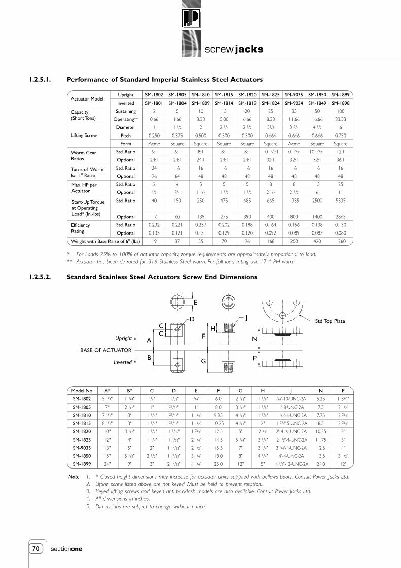
70
screw jacks
sectionone
SM-1802
SM-1801
2
0.66
1
0.250
Acme
6:1
24:1
24
96
21/2
40
17
0.232
0.133
19
SM-1805
SM-1804
5
1.66
1 1/2
0.375
Square
6:1
24:1
16
64
43/4
150
60
0.221
0.121
37
SM-1810
SM-1809
10
3.33
2
0.500
Square
8:1
24:1
16
48
5
1 1/2
250
135
0.237
0.151
55
SM-1815
SM-1814
15
5.00
2 1/4
0.500
Square
8:1
24:1
16
48
5
1 1/2
475
275
0.202
0.129
70
SM-1820
SM-1819
20
6.66
2 1/2
0.500
Square
8:1
24:1
16
48
5
1 1/2
685
390
0.188
0.120
96
SM-1825
SM-1824
25
8.33
33/8
0.666
Square
10 2/3:1
32:1
16
48
8
2 1/2
665
400
0.164
0.092
168
SM-9035
SM-9034
35
11.66
3 3/4
0.666
Acme
10 2/3:1
32:1
16
48
8
2 1/2
1335
800
0.156
0.089
250
SM-1850
SM-1849
50
16.66
4 1/2
0.666
Square
10 2/3:1
32:1
16
48
15
6
2500
1400
0.138
0.083
420
SM-1899
SM-1898
100
33.33
6
0.750
Square
12:1
36:1
16
48
25
11
5335
2865
0.130
0.080
1260
Upright
Inverted
Sustaining
Operating**
Diameter
Pitch
Form
Std. Ratio
Optional
Std. Ratio
Optional
Std. Ratio
Optional
Std. Ratio
Optional
Std. Ratio
Optional
Actuator Model
Capacity(Short Tons)
Start-Up Torqueat OperatingLoad* (In.-lbs)
EfficiencyRating
Lifting Screw
Worm GearRatios
Turns of Wormfor 1" Raise
Max. HP perActuator
Weight with Base Raise of 6" (lbs)
Model No
SM-1802
SM-1805
SM-1810
SM-1815
SM-1820
SM-1825
SM-9035
SM-1850
SM-1899
A*
5 1/4"
7"
7 1/2"
8 1/2"
10"
12"
13"
15"
24"
B*
1 3/4"
2 1/2"
3"
3"
3 1/2"
4"
5"
5 1/2"
9"
C3/4"
1"
1 1/4"
1 1/4"
1 1/2"
1 3/4"
2"
2 1/2"
3"
E3/4"
1"
1 1/4"
1 1/2"
1 3/4"
2 1/4"
2 1/2"
3 1/4"
4 1/4"
D13/32"21/32"25/32"29/32"
1 1/32"
1 9/32"
1 17/32"
1 21/32"
2 17/32"
F
6.0
8.0
9.25
10.25
12.5
14.5
15.5
18.0
25.0
G
2 1/2"
3 1/2"
4 1/4"
4 1/4"
5"
5 3/4"
7"
8"
12"
H
1 1/8"
1 1/8"
1 5/8"
2"
21/4"
3 1/4"
3 3/4"
4 1/4"
5"
N
5.25
7.5
7.75
8.5
10.25
11.75
12.5
13.5
24.0
P
1 3/4"
2 1/2"
2 3/4"
2 3/4"
3"
3"
4"
3 1/2"
12"
J3/4"-10-UNC-2A
1"-8-UNC-2A
1 1/2"-6-UNC-2A
1 3/4"-5-UNC-2A
2"-4 1/2-UNC-2A
2 1/2"-4-UNC-2A
3 1/4"-4-UNC-2A
4"-4-UNC-2A
4 1/2"-12-UNC-2A
1.2.5.1. Performance of Standard Imperial Stainless Steel Actuators
* For Loads 25% to 100% of actuator capacity, torque requirements are approximately proportional to load.** Actuator has been de-rated for 316 Stainless Steel worm. For full load rating use 17-4 PH worm.
1.2.5.2. Standard Stainless Steel Actuators Screw End Dimensions
Note 1. * Closed height dimensions may increase for actuator units supplied with bellows boots. Consult Power Jacks Ltd.2. Lifting screw listed above are not keyed. Must be held to prevent rotation.3. Keyed lifting screws and keyed anti-backlash models are also available. Consult Power Jacks Ltd.4. All dimensions in inches.5. Dimensions are subject to change without notice.
E
DCC
A
J
B
F
G
H
P
NUpright
Std Top Plate
Inverted
BASE OF ACTUATOR

71
screw jacks
sectionone
1.2.5.3 Imperial Stainless Steel Actuator Dimensions
Mod
elN
o
SM-1
802
SM-1
805
SM-1
810
SM-1
815
SM-1
820
SM-1
825
SM-9
035
SM-1
850
SM-1
899
Sust
aini
ng
2 5 10 15 20 25 35 50 100
Ope
ratin
g
0.66
1.66
3.33
5.00
6.66
8.33
11.6
6
16.6
6
33.3
3
Cap
acity
(Sh
ort T
ons)
S 3.5
8.00
8.75
9.25
11.0
0
13.7
5
15.5
0
9.75
20.7
5
R 1.75
3.00
2.88
3.38
4.13
5.13
6.00
4.88
8.00
T 3.5
4.50
5.50
5.50
5.50
7.00
7.00
11.0
0
11.5
0
V 1.12
1.50
1.80
1.80
1.50
2.30
2.10
4.40
3.40
X .41
.69
.81
.81
.81
1.06
1.62
1.38 *
Y 3.00
3.00
4.13
4.13
4.13
6.00
7.75
8.75 *
Z .41
.69
.81
.81
1.12
1.38
1.62
1.88 •
a .75
1.19
1.31
1.38
1.75
2.13
2.63
3.25 *
b 1.5
.75
.88
.88
1.13
1.38
1.38
1.88 *
Keys
eat
(b x
h x
L)
.125
x 0
.060
x 1
.00
LG
.188
x .0
94 x
1.2
5 LG
.250
x .1
25 x
1.5
0 LG
.250
x .1
25 x
1.5
0 LG
.250
x .1
25 x
1.5
0 LG
.313
x .1
56 x
2.0
0 LG
.313
x .1
56 x
2.0
0 LG
.375
x .1
88 x
2.2
5 LG
.500
x .2
50 x
3.0
0 LG
U 7.00
9.00
11.0
0
11.0
0
11.0
0
14.0
0
14.0
0
22.0
0
23.0
0
Q 7.00
6.00
7.50
7.75
8.25
10.2
5
10.2
5
19.7
5
24.5
0
P 3.5
3.00
3.75
3.88
4.13
5.13
5.13
9.88
12.2
5
N 2.00
6.50
7.00
7.50
8.75
11.0
0
12.5
0
6.00 *
M 1.00
2.25
2.00
2.50
3.00
3.75
4.50
3.00 *
H .50
.60
.94
.94
.94
.94
1.31
1.25
2.94
.500
.749
1.00
0
1.00
0
1.00
0
1.37
5
1.37
5
1.50
0
1.75
0
+.0
00-.0
02
+.0
00-.0
02
+.0
00-.0
02
+.0
00-.0
02
+.0
00-.0
02
+.0
00-.0
02
+.0
00-.0
02
+.0
00-.0
02
+.0
00-.0
02
D .50
.50
.50
.63
.75
1.00
1.25
1.25
1.50
G 4.25
4.50
5.75
5.75
5.75
8.50
10.5
0
11.2
5
14.0
0
F
1.66
2.38
2.88
2.88
3.50
4.50
4.50
5.63
7.00
L
6.00
4.50
5.75
6.00
6.00
7.50
7.50
16.0
0
*
K 3.00
2.25
2.88
3.00
3.00
3.75
3.75
8.00 *
J
1.70
2
2.18
8
2.59
8
2.59
8
2.59
8
3.75
0
3.75
0
5.31
3
7.50
0
+.0
03-.0
00
+.0
03-.0
00
+.0
03-.0
00
+.0
03-.0
00
+.0
03-.0
00
+.0
03-.0
00
+.0
03-.0
00
+.0
03-.0
00
+.0
03-.0
00
WE
1.75
0
±.00
5
2.25
0
±.00
5
2.25
0
±.00
5
2.75
0
±.00
5
3.25
0
±.00
5
4.00
0
±.00
5
4.00
0
±.00
5
4.75
0
±.00
5
6.00
0
±.00
5
B 4.56
5.88
6.00
6.31
8.00
9.75
9.56
11.3
8
18.5
0
A 5.50
7.50
7.75
8.00
10.2
5
11.7
5
12.5
0
13.5
0
24.0
0
C
Trav
el
Trav
el
+3 /
8
Trav
el
+1 /
4
Trav
el
+1 /
2
Trav
el-1
/4
Trav
el
+1 /
4
Trav
el
+1 /
4
Trav
el
Trav
el
+1 /
2
Mo
del
189
9 (1
00 T
on
) M
ou
nti
ng
Ho
le P
atte
rn
Not
e:1.
Dim
ensio
ns a
re s
ubje
ct t
o ch
ange
with
out
notic
e.3.
Dim
ensio
ns in
inch
es.
5.RH
S =
Rig
ht H
and
Side
2.Fo
r m
odel
s SM
1802
and
SM
-185
0 st
yle
as p
er s
ectio
n 1.
2.3.
2.4.
LHS
= L
eft
Han
d Si
de
D
E
GH
B
A(C
lose
dH
eigh
t)
C
F
Lift
ing
Scre
wT
QP
LK
V
SW
U
Key
Sea
t
JN
RM
Four
Hol
es “
Z”
Dia
“a”
Dia
Spo
tfac
e
“b”
Rad
ius
Four
Hol
es “
X”
Dia
equ
ally
spac
ed o
n “Y
” D
ia P
.C.
RHS
LHS
Six
hole
s 1.
88”
Dia
equa
l ly s
pace
d on
11 ”
P.C
. Dia
8.13
”
8.13
” 5.75
”
10.0
”20
.0”
Six
Hol
es 1
.85”
Dia
3.50
” D
ia S
potf
ace

72
screw jacks
sectionone
1.2.6. Micro Miniature Actuator
Manual operation is accomplished with an easy to use hand knob. The dial indicator is protected by a removable clearplastic cover.
Dial indicators available on request. Indicate preference when ordering:
• Dial SK-3554-46Balanced dial reading 0 → 50 → 0 inches with 0.001” graduations with revolution counter.
• Dial SK-3554-83Continuous dial reading 0 → 100 inches in 0.001” graduations with revolution counter.
• Metric DialDial readings with 0 → 50 → 0mm or 0 →100mm with 0.01mm graduations with revolutioncounter.
(Type of dial must be specified as above when ordering the actuator)
• Actuates up to 450 kg (1,000 lb).
• Allows for extremely fine adjustment.
• Equipped with anti-backlash nuts to minimise vertical backlash between lifting screw and worm gear nut.
• Standard model has anodised aluminium shell cap and housing with stainless steel worm and lifting screws.
• Stainless Steel option has sealed 316 stainless steel shell cap, housing, worm and lifting screw.
Note The load bearings and worm bearings inside stainless steel actuators are not stainless steel.
1.2.6.1. Micro Miniature Actuator Specification
Lifting Torqueat Full Load
(inch)
0.500
0.625
0.625
in.lb
12
18
18
M-3554-30
M-3554-27
M-3554-136
(kg)
225
450
450
ModelShell Cap& Housing
Aluminium
Aluminium
Stainless Steel
(lb)
500
1000
1000
RatedCapacity
ScrewDia.
Turns ofWorm for1/2" Raise
500
500
500
Nm
1.36
2.03
2.03
WormGear Ratio
20:1
20:1
20:1
(kg)
0.91
0.91
1.36
(lb)
2
2
3
Weight
Patent Numbers:3,220,277 and
3,323,777
Note 1. All dimensions in inches unless otherwise stated.2. Dimensions are subject to change without notice.
2 7/8” Dia1” Dia
3 5/8” Dia± 1/18”
2”1 1/2”
1 5/8”
3 1/4”
2”
4”
5/16”1/2”
1”
.941”.938””
.375”
.373” Dia
2 1/4”
1 1/8”
2 7/8” O/Dia
4” ±1/16”
2 7/8” ±1/16””
3”ClosedHeight
2 5/8” I/Dia
2 1/4”
Dia
RemovableIndicatorCover(Clear Lucite)
1.003”.997”5/16”
1/2” Maximum Travel
1” 3/4” 3/8”-24-UNF-2A Thread
.375”
.372”
FullThread
2 holes 7/16” Dia

73
screw jacks
sectionone
Shell CapAdjustable to take end playout of bearings. Locked into
place by set screws.
Load BearingsTop and bottom to takeloads in either direction.
Worm GearAluminium Bronze.
Accurately hobbed forgreater gear contact.
WormAvailable with double
or single shaft extension.fitted with key as standard.
Thrust Bearingsand Grease SealsAt each end of worm.
Stop DiscThis is not a power stop.
For positive stop wesuggest external stops be
used in structure.
HousingAluminium on 10kN model.Ductile iron on 25kN through100 kN models, cast steel on200 kN through 500 kN models.
Ball NutInternal continuous recirculation ofsteel balls. Threaded and secured to
worm gear. Equipped withINTEGRAL SAFETY DEVICE.
Guide Bush
Lifting ScrewStandard withthreaded end.
Bottom PipeProtects lifting screw threads.
1.3. Ball Screw Actuator
1.3.1. E-Series Metric Ball Screw Jacks
Advantages• Move Loads and apply force more efficiently than other mechanical actuators.
• Permit faster operation and longer life under load.
• Require less power by providing positive mechanical action.
• Permit synchronisation of multiple units.
• Capacity from 10 kN → 500 kN.
• Handles full load in tension or compression.
• 40 models available.
• Integral ball screw safety device.
The metric ball screw gives you a single-package, positive action linear actuator that can be driven by an electric, air or hydraulic motor.A ball-bearing type heat-treated screw and mating nut with rolling contact reduces friction to a bare minimum in converting torque tothrust. Overall operating efficiency is as high as 70% in some models, depending on the worm gear ratio.
Metric ball screw actuators are available as translating or rotating screws in either upright or inverted configurations. In the translatingscrew type, the ball nut is fixed to the gear and the lifting screw moves up and down through the nut. In the rotating screw type, thescrew is fixed to the gear and the ball nut travels along the screw.
Depending on size and type of load, models are available with raises up to 3 metres. Raises up to 6 metres are available on request.Metric ball screw actuators may be used individually, in tandem or in multiple arrangements. Special models are available and there is noextra charge for single ended worm shafts extensions.

74
screw jacks
sectionone
Upright Screw
Rotating Screw (Upright)Available in both upright
and inverted types Inverted Screw
Threaded
Metric Ball Screw Actuator Models
Features• Integral Safety Device - All Power Jacks Metric ball screw actuator except Model E28501 have an integral safety
device as standard. This provides two important safety roles: (a) wear indicator and (b) sustain the load in theunlikely event of catastrophic ball failure. For further details refer to section 1.3.1.1.2.
• High Speed - Low friction permits linear motion in some models up to 6 m/min at 1800 rpm worm shaft speeds,providing maximum power ratings are not exceeded.
• Precise Positioning - Can be controlled accurately for positioning within hundredths of a millimetre.
• Positive Action - Operates with a high degree of reliability, without the need for costly pumps, hoses or valves.
• Uniform Lifting Speed - Highly efficient design means less power is needed to achieve a given thrust; power needs areas much as two-thirds that of machine screw actuators, with savings in motors, couplings, reducers, shafting and controls.
• Long-Life - Low friction means longer operating life.
• Low Power Usage - Highly efficient design means less power is needed to achieve a given thrust; power needs areas much as two-thirds that of machine screw actuators.
• Internal Recirculating Balls - For smooth movement, less turns per circuit and absence of parts liable to wear.
Options• 2 Standard Gear Ratios.
• 2 Ball Screw Lead Options as Standard - Other leads are available on request.
• Pre-Loaded Ball Screw - These ball screw assemblies give zero linear backlash (available on request).
• Anti-Rotation Device - Stops a translating screw from rotating when the screw end is free.
• Bellows Boot Option - Protects the screw from dust, dirt, moisture and corrosive contaminants.
• Secondary Guide Option - Increases a lifting screw lateral rigidity aiding screw guidance and improved side load resilience.
• Double Clevis End Option - Incorporates a special clevis end bottom pipe and a standard clevis end on the lifting screw.
Note Clockwise rotation of worm raises load on all models - counter clockwise available at extra charge.Unless a translating screw has an anti-rotation device, the lifting screw end should be bolted to the lifting member toprevent the screw from rotating.Actuators are equipped with "Alemite" grease fittings.Recommended lubricants are listed in the installation and maintenance instructions.Actuators supplied complete with drive shaft keys.
Attachments
IEC and NEMA flange, motors, gearboxes, reducers and couplings available for single actuator drive or multiple actuator arrangements(refer 4, 6, 7 and 8).
Motion control components include electronic motion controllers, motor drives, operator interfaces, encoders, limit switches,potentiometers and meters with LCD display (refer 8).
Clevis
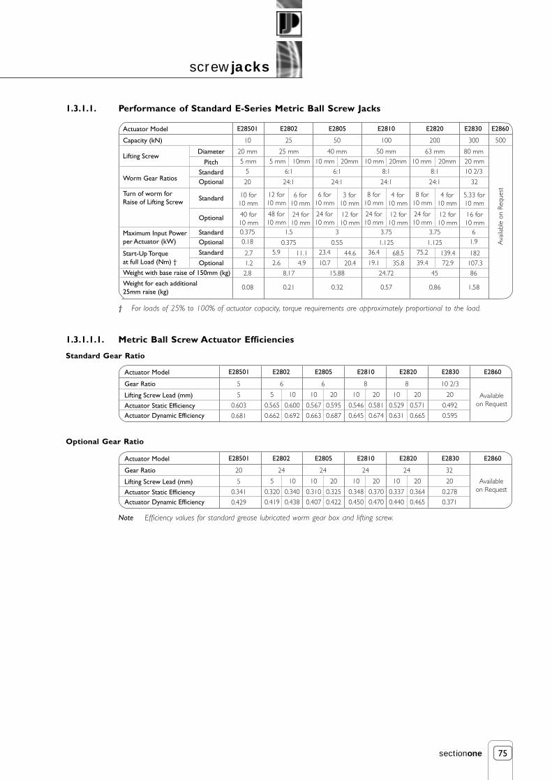
75
screw jacks
sectionone
Actuator Model
Capacity (kN)
Lifting Screw
Worm Gear Ratios
Turn of worm forRaise of Lifting Screw
Diameter
StandardOptional
Pitch
E2802 E2805 E2810 E2820 E2830 E2860
Standard
Optional
Maximum Input Powerper Actuator (kW)
Start-Up Torqueat full Load (Nm) †
Weight with base raise of 150mm (kg)
Weight for each additional 25mm raise (kg)
StandardOptional
Standard
Optional
25
25 mm
6:1
24:1
5 mm 10mm
12 for10 mm
48 for10 mm
6 for10 mm
24 for10 mm
1.5
0.375
8.17
0.21
5.9 11.12.6 4.9
E28501
10
20 mm
5
20
5 mm
10 for10 mm
40 for10 mm0.3750.18
2.8
0.08
2.71.2
300
80 mm
10 2/3
20 mm
5.33 for10 mm
16 for10 mm
61.9
86
1.58
182107.3
50
40 mm
6:1
24:1
10 mm 20mm
6 for10 mm
24 for10 mm
3 for10 mm
12 for10 mm
3
0.55
15.88
0.32
23.4 44.610.7 20.4
100
50 mm
8:1
24:1
10 mm 20mm
8 for10 mm
24 for10 mm
4 for10 mm
12 for10 mm
3.75
1.125
24.72
0.57
36.4 68.519.1 35.8
200
63 mm
8:1
24:1 32
10 mm 20mm
8 for10 mm
24 for10 mm
4 for10 mm
12 for10 mm
3.75
1.125
45
0.86
75.2 139.439.4 72.9
500
Ava
ilabl
e on
Req
uest
Actuator Model
Gear Ratio
Lifting Screw Lead (mm)
Actuator Static EfficiencyActuator Dynamic Efficiency
E2802E28501 E2805 E2810 E2820 E2830 E2860
65
5
0.603
0.681
0.565 0.600
6
0.567 0.595
8
0.546 0.581
8
0.529 0.571
5 10 10 20 10 20 10 20
0.662 0.692 0.663 0.687 0.645 0.674 0.631 0.665
10 2/3
0.492
20
0.595
Availableon Request
Actuator Model
Gear Ratio
Lifting Screw Lead (mm)
Actuator Static EfficiencyActuator Dynamic Efficiency
E2802E28501 E2805 E2810 E2820 E2830 E2860
2420
5
0.341
0.429
0.320 0.340
24
0.310 0.325
24
0.348 0.370
24
0.337 0.364
5 10 10 20 10 20 10 20
0.419 0.438 0.407 0.422 0.450 0.470 0.440 0.465
32
0.278
20
0.371
Availableon Request
1.3.1.1. Performance of Standard E-Series Metric Ball Screw Jacks
† For loads of 25% to 100% of actuator capacity, torque requirements are approximately proportional to the load.
1.3.1.1.1. Metric Ball Screw Actuator Efficiencies
Standard Gear Ratio
Optional Gear Ratio
Note Efficiency values for standard grease lubricated worm gear box and lifting screw.
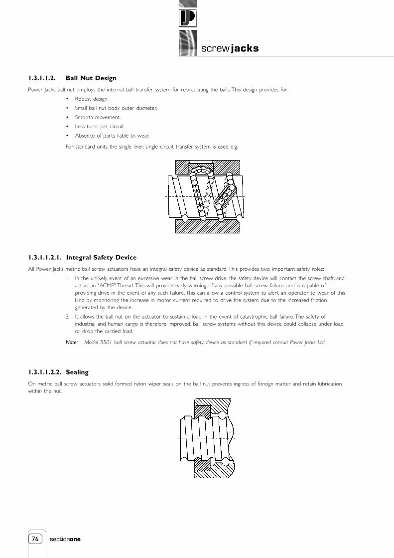
76
screw jacks
sectionone
1.3.1.1.2. Ball Nut Design
Power Jacks ball nut employs the internal ball transfer system for recirculating the balls. This design provides for :
• Robust design.
• Small ball nut body outer diameter.
• Smooth movement.
• Less turns per circuit.
• Absence of parts liable to wear.
For standard units the single liner, single circuit transfer system is used e.g.
1.3.1.1.2.1. Integral Safety Device
All Power Jacks metric ball screw actuators have an integral safety device as standard. This provides two important safety roles:
1. In the unlikely event of an excessive wear in the ball screw drive, the safety device will contact the screw shaft, andact as an "ACME" Thread. This will provide early warning of any possible ball screw failure, and is capable ofproviding drive in the event of any such failure. This can allow a control system to aler t an operator to wear of thiskind by monitoring the increase in motor current required to drive the system due to the increased frictiongenerated by the device.
2. It allows the ball nut on the actuator to sustain a load in the event of catastrophic ball failure. The safety ofindustrial and human cargo is therefore improved. Ball screw systems without this device could collapse under loador drop the carried load.
Note: Model 5501 ball screw actuator does not have safety device as standard if required consult Power Jacks Ltd.
1.3.1.1.2.2. Sealing
On metric ball screw actuators solid formed nylon wiper seals on the ball nut prevents ingress of foreign matter and retain lubricationwithin the nut.

77
screw jacks
sectionone
1.3.1.1.2.3. Preloaded for Reduced Axial Backlash
Power Jacks Metric Ball Screw Actuators can be provided with preloaded ball nuts to give reduced axial backlash as a high efficiencyalternative to the metric machine screw anti-backlash option. The preloading on the ball nut is obtained by the "Interference Ball"method. By fitting interference balls in the ball nut to obtain a diametral interference fit and using the ogival track form, a four-pointcontact results e.g.
1.3.1.1.3. Ball Screw Life
Theoretical service life can be expressed in either L10
106 revolutions or Lh103 hours or L
d kilometres. As the life of a ball screw is
determined by metal fatigue it is not possible to accurately predict life. However, it is practical to suppose that 90% of a sufficiently largenumber of equally sized ball screws running under equal working conditions will reach L
10 or L
h without evidence of material fatigue.
The L10 ball screw life is rated using the Dynamic Capacity, which is the maximum constant axial load that can be applied in runningconditions for a life of 1.106 revolutions of the ball screw. This can be expressed in linear travel (Ld).
Where L10 = Service Life (millions of revolutions)
L d = L10 * P Ld = Service Life (km)
P = Pitch of Ball Screw (mm)
Working Load (kN)Linear Travel Ld in km
5 10 25 30 50 75 100 150 200Actuator
Model
Actuator Rating(kN)
Actuator Pitch(mm)
E28501
E2802
E28021
E2805
E28051
E2810
E28101
E2820
E28201
E2830
10
25
25
50
50
100
100
200
200
300
5
5
10
10
20
10
20
10
20
30
20.5
381
1 775
11 978
17 039
32 287
38 503
162 327
320 060
903 882
2.5
48
222
1 497
2 130
4 036
4 813
20 291
40 008
112 985
-
3
14
96
136
258
308
1 299
2 560
7 231
-
-
-
55
79
149
178
752
1 482
4 185
-
-
-
12
17
32
39
162
320
904
-
-
-
-
-
10
11
48
95
268
-
-
-
-
-
4
5
20
40
113
-
-
-
-
-
-
-
6
12
33
-
-
-
-
-
-
-
3
5
14
250 300
-
-
-
-
-
-
-
-
-
7
-
-
-
-
-
-
-
-
-
4
Four Point Contact
Use the following formulae to calculate the service life in terms of hours running:
Where Lh = Service Life (hours)
L10 = Service Life (revolutions)
nm = Mean Actuator Input Speed (rpm)
Gr = Actuator Gear Ratio
Note: Ball screw life based on dynamic load calculated according to DIN69051 Part 4.
L10 * Gr
60 * nm
L h =

78
screw jacks
sectionone
A
I
C
B
AA
H
D
F
G
E
B1
BB
C1
A
Upright Inverted
1.3.1.2. Metric Ball Screw Actuator Dimensions
1.3.1.2.1. Standard Metric Translating Screw Actuators
Plan View
Note 1. All dimensions in mm.2. Dimensions are subject to change without notice.3. LHS = Left Hand Side4. RHS = Right Hand Side
SU
TVN
O
P
Q
R
W
X
K
J
L
M
Models:
2802, 28021, 2805,28051, 2810, 28101,
2820, 28201,2830, 2860.
Model:
28501
N
O
P
Q
R
W
XK
J
M RHS
LHS
RHS
LHS
L

79
screw jacks
sectionone
ModelABCDEFGHIJKL
E2802Ø100
P.C.D. 70Ø4031.512
Ø13.5Ø4079.54623
Ø1630
E28021 E2805Ø120
P.C.D. 85Ø5036.516
Ø18Ø5091.56030
Ø2035
E28051 E2810Ø150
P.C.D. 110Ø654220
Ø22Ø651206633
Ø2240
E28101 E2820Ø170
P.C.D. 120Ø755825
Ø26Ø751438040
Ø3050
E28201 E2830Ø240
P.C.D. 170Ø110
6730
Ø33Ø11016712060
Ø4580
E2860Ø280
P.C.D. 215Ø150
9235
Ø33Ø15021715075
Ø60110
Availableon request
UprightInvertedUprightInverted
M
N
191.581.5166.556.5
211.581.5186.556.5
Ø80P.C.D. 55
Ø302410
Ø11Ø30633618
Ø1220
E28501
1504517065
241.591.5216.566.5
281.591.5256.566.5
29212724782
32212727782
36114331698
39914335498
485155445115
ABB1CC1DEFGHIJKLMNOPQRSTUV
W
XAABB
A + 10A + 25
5525
48.345 ± 0.13
13M20 X 2.5
3018090
Ø16 h85 X 5 X 25
13.51105580401656513550
43.26+ 0.025- 0.02527.5
A + 10A + 25
6540
60.360 ± 0.13
14M24 X 3
35230115
Ø19 h86 X 6 X 32
181507511557.52057517057.555.58
+ 0.050- 0.000
35
A + 15A + 25
805073
60 ± 0.1316
M36 X 440280140
Ø25 h88 X 7 X 40
221909514572.52257518052.566
+ 0.060- 0.000
44
A + 10A + 25
956389
85 ± 0.1320
M48 X 555300150
Ø28 h88 X 7 X 40
26210105150752751052157566
+ 0.070- 0.000
44
E2802E2801
UprightInvertedModel
Capacity (kN)
E28021E28011
E2805E2804
E28051E28041
E2810E2809
E28101E28091
E2820E2819
E2830E2829
Raise As Required25 50 100 200 300
E2860E2859
500
165 185 215 255 245 275 313 351
124 144124
A + 35A + 35
150452042
40 ± 0.139
M12 X 1.752415075
Ø14 h85 X 5 X 25
111306510050----
31.75+ 0.076- 0.000
36
E28501E28500
10
114114 144
169 209169 209
190 220190 220
243 281243 281
A + 30A + 25
11580115
105 ± 0.1330
M72 X 465380190
Ø35 h810 X 8 X 50
3926013019095365140295105
95.25+ 0.130- 0.000
56
445
360360
Ava
ilabl
e on
Req
uest
1.3.1.2.2. Standard Translating Ball Screw Ends
F
Top Plate Clevis End
N
C
D
BA
E L
K
JI
H
G
M
AC
TU
ATO
R B
ASE
AC
TU
ATO
R B
ASE

80
screw jacks
sectionone
UE-2803UE-28031UE-2806UE-28061UE-2811UE-28111UE-2821UE-28211UE-2831UE-2861
Model No Rating (KN) A B C D E F
25
50
100
200
300500
25
30
50
65
85
103.5
138
146.5
195
235
0
0
28
24
40
20
25
35
45
75
HG
15
20
25
35
48
90
120
155
185
230
40
60
70
85
120
4 Holes - 13.5 Dia. on 65 Dia. P.C.D.
4 Holes - 18 Dia. on 90 Dia. P.C.D.
4 Holes - 22 Dia. on 115 Dia. P.C.D.
4 Holes - 26 Dia. on 135 Dia. P.C.D.
4 Holes - 26 Dia. on 175 Dia. P.C.D.
Raise + 80Raise + 100Raise + 105Raise + 145Raise + 130Raise + 160Raise + 150Raise + 190Raise + 240
I J
628287124104134125163200
UE-28502 10 16 90 0 12 12 55 326 Holes - 7 Dia. on 45 Dia. P.C.D.Raise + 74 44
Available on Request
DE-2803DE-28031DE-2806DE-28061DE-2811DE-28111DE-2821DE-28211DE-2831DE-2861
Model No Rating (KN) A B C D E F
25
50
100
200
300500
25
30
50
65
95.5
122
130.5
179
13.5
18
26.5
25
95.5
122
130.5
203
IG
20
25
35
45
90
120
155
185
40
60
70
85
4 Holes - 13.5 Dia. on 65 Dia. P.C.D.
4 Holes - 18 Dia. on 90 Dia. P.C.D.
4 Holes - 22 Dia. on 115 Dia. P.C.D.
4 Holes - 26 Dia. on 135 Dia. P.C.D.
Raise + 80Raise + 100Raise + 105Raise + 145Raise + 130Raise + 160Raise + 150Raise + 190
J K
628287124104134125163
DE-28502 10 16 90 10 90 44
200
55
H
15
20
25
35
85 235 25 275 75 230 1204 Holes - 26 Dia. on 175 Dia. P.C.D.48
12 326 Holes - 7 Dia. on 45 Dia. P.C.D.Raise + 74
Raise + 240
12
Available on Request
1.3.1.2.3. Standard Rotating Ball Screw Actuators
For other dimensions and performance data refer to translating actuators.
1.3.1.2.3.1. Upright Rotating Ball Screw
1.3.1.2.3.2. Inverted Rotating Ball Screw Actuator
A CF
G
D
HB
Pilot
Lifting Nut ShellAdjustableShell Cap
Dia E
Mounting Plate
Bottom Pipe
I
ACG
H
B
Pilot
Lifting NutShellAdjustableShell Cap
F Dia
DE
MountingPlate
Top Pipe IDia
J
KDia
JDia

81
screw jacks
sectionone
1.3.1.3. Bellows Boots for Metric Actuators
Features
• Protects the screw from dust and dirt.
• Guards against moisture and corrosive contaminants.
• Helps maintain the proper lubrication.
• Boots are made of P.V.C. coated nylon with sewn construction. Other materialsare available for applications involving high temperatures, highly corrosiveatmospheres and other special conditions.
1.3.1.3.1. Boot Dimensions
Note 1. F = Bellows boot minimum closed thickness.2. - = Not applicable consult Power Jacks Ltd.3. † = Control tapes fitted (approximately 20 mm increase to outer diameter).
E28501-B
E2802-B
E2805-B
E2810-B
E2820-B
E2830-B
E2860-B
A
30
40
50
65
75
B
75
66
85
100
105
C
114
120
140
150
165
D
12
15
15
15
20
E
12
15
15
15
20
Model
Available on Request
Available on Request
D
F
E
B
C
A
Raise 0 300
Raise 300 600
Raise 600 900
Raise 600 1050
Raise 900 1050
Raise 1050 1500
Raise 1500 1800
Raise 1500 2000
Raise 1800 2100
Raise 2000 2500
Raise 2100 2500
Raise 2500 3000
32
-
56
-
80
-
-
-
-
-
-
E28501-B
16
Model E2805-B
20
E2810-B
20
E2820-B
20
E2830-B E2860-B
F
30
45
-
50
70
95
-
110
-
130
160
30
-
50
-
70
-
105
-
120
-
-
30
-
50
-
70
90
-
110
-
-
-
30
-
50
-
70
100
-
-
-
-
-
E2802-B
20
Ava
ilabl
e on
Req
uest
Ava
ilabl
e on
Req
uest

82
screw jacks
sectionone
Closed Heights
G G G + H
1.3.1.3.2. Upright Metric Ball Screw Actuators with Bellows Boots
1.3.1.3.2.1. Standard Dimensions for all Upright Metric Ball Screw Actuators
Threaded End Clevis EndTop Plate
Note 1. Supplied complete with a set of corrosion-resistant 'jubilee' clips (2) suitable for fitting over collar diameters2. † Control tapes are fitted (approximately 20 mm increase to outer diameter).3. For horizontal installation exceeding 450 mm of travel, internal boot guides are recommended.4. Customers with threaded end actuators must provide a fixing for the unattached collar (★ ).5. Bellows boots for Rotating Screw Actuators consult Power Jacks Ltd.6. For other sizes, raises, and materials please consult Power Jacks Ltd.7. All dimensions in millimetres unless otherwise stated.
Raise 0 150
Raise 0 300
Raise 300 600
Raise 600 900
Raise 600 1050
Raise 900 1050
Raise 1050 1500
Raise 1500 1800
Raise 1500 2000
Raise 1800 2100
Raise 2000 2500
Raise 2100 2500
Raise 2500 3000
Extra Closed Heightfor Clevis
-
180
190
-
210
-
230
260
-
-
-
-
-
25
E2802-BModel E28021-B E2805-B E28051-B E2810-B
G
H
-
200
210
-
230
-
250
280
-
-
-
-
-
25
-
230
240
255
-
260
280
305
-
320
-
340
370
25
-
270
280
295
-
300
320
345
-
360
-
380
410
25
E28101-B
-
285
295
-
315
-
335
-
370
-
385
-
-
45
E2820-B
-
323
333
-
353
-
373
393
-
413
-
-
-
45
E28201-B
-
361
371
-
391
-
411
431
-
451
-
-
-
45
E2830-B & E2860-B
-
255
265
-
285
-
305
-
340
-
355
-
-
45
-
166
182
-
206
-
230
-
-
-
-
-
-
20
E28501-B
Ava
ilabl
e on
Req
uest

83
screw jacks
sectionone
★
J
Closed Heights
J
Boot Mounting Plate,to suit collar size.Typically
ØB x (E+5 mm fittingallowance) thick.
J+K
Actuator Mounting Plate,‘M’ thick. Alter thicknessto suit application.
1.3.1.3.3. Inverted Metric Ball Screw Actuators with Bellows Boots
1.3.1.3.3.1. Standard Dimensions for all Inverted Metric Ball Screw Actuators
1.3.1.3.4. Notes for all Metric Ball Screw Actuators with Bellows Boots
Note 1. Supplied complete with a set of corrosion-resistant 'jubilee' clips (2) suitable for fitting over collar diameters.2. † Control tapes are fitted (approximately 20 mm increase to outer diameter).3. For horizontal installation exceeding 450 mm of travel, internal boot guides are recommended.4. Customers with threaded end actuators must provide a fixing for the unattached collar (★ ).5. Bellows boots for Rotating Screw Actuators consult Power Jacks Ltd.6. For other sizes, and materials please contact Power Jacks Ltd.7. All dimensions in millimetres unless otherwise stated.8. Dimensions subject to change without notice.
Mounting Plate Thickness
Raise 0 150
Raise 0 300
Raise 300 600
Raise 600 900
Raise 600 1050
Raise 900 1050
Raise 1050 1500
Raise 1500 1800
Raise 1500 2000
Raise 1800 2100
Raise 2000 2500
Raise 2100 2500
Raise 2500 3000
Extra Closed Height For Clevis
E2801-B &E28011-B
Model
J
M
K
15
-
100
110
-
130
-
150
180
-
-
-
-
-
25
E2804-B &E28041-B
15
-
105
115
130
-
135
155
170
-
185
-
205
235
25
E2809-B &E28091-B
20
-
120
130
-
150
-
170
-
195
-
210
-
-
45
E2819-B &E28191-B
20
-
140
150
-
170
-
190
210
-
230
-
-
-
45
E2829-B& E2859-B
Ava
ilabl
e on
Req
uest
30
E28501-B
10
-
61
77
-
101
-
125
-
-
-
-
-
-
20

84
screw jacks
sectionone
B
45o
45o
1.3.1.4. Standard Flange Bolt Configuration for Worm Shafts
Model 'B' Bolt P.C.D. (mm) Bolt Information
E28501
E2802
E2805
E2810
E2820
E2830
-
46
61
70
88
107
-
M6 x 1 mm Pitch, 14 mm Deep
M8 x 1.25 mm Pitch, 22 mm Deep
M8 x 1.25 mm Pitch, 14 mm Deep
M10 x 1.5 mm Pitch, 14 mm Deep
M10 x 1.5 mm Pitch, 19 mm Deep
ModelCCE2802
Capacity (kN) 25
250
192
58
23
48.3
30
16
280
CCE28501
10
CCE28021
25
270
212
58
23
48.3
30
16
200
CCE2805
50
310
242
68
30
60.3
35
20
600
CCE28051
50
350
282
68
30
60.3
35
20
560
CCE2810
100
420
292
128
33
73
40
22
658
CCE28101
100
450
322
128
33
73
40
22
588
CCE2820
200
500
361
139
40
102
50
30
769
CCE28201
200
538
399
139
40
102
50
30
621
CCE2830
300
CCE2860
500
A
B
C
D
E
F
GMax Raise at Max RatedLoad in Compression
Ava
ilabl
e on
Req
uest
Ava
ilabl
e on
Req
uest
Ava
ilabl
e on
Req
uest
Note 1. All dimensions in millimetres unless otherwise stated.2. Dimensions subject to change without notice.
1.3.1.5. Metric Double Clevis End Ball Screw Actuators
F
Note 1. For other performance and dimension information refer to translating screw models.2. All dimensions in millimetres unless otherwise stated.3. Dimensions subject to change without notice.
StandardClevis
G
E
DD
B
Raise + A
Raise + CRaise

85
screw jacks
sectionone
1.3.1.6. Motor Adaptors for Metric Ball Screw Actuators
Dimensions and details are the same as for Metric Machine Screw Actuators.
Please refer to section 1.2.2.11.
1.3.1.7. Trunnion Mounts for Metric Ball Screw Actuators
Dimensions and details are the same as for Metric Machine Screw Actuators.
Please refer to section 1.2.2.12.
1.3.1.8. Rotary Limit Switch Adaptors for Metric Ball Screw Actuators
Dimensions and details are the same as for Metric Machine Screw Actuators.
Please refer to sections 1.2.2.13. and 1.2.2.14.
1.3.1.9. Limit Switches Mounted on Metric Ball Screw Actuator Bottom Pipes
Dimensions and details are the same as for Metric Machine Screw Actuators.
Please refer to section 1.2.2.16.

86
screw jacks
sectionone
Note 1. AOR = Application On Request, consult Power Jacks Ltd.2. All dimensions in millimetres unless otherwise stated.3. Dimensions subject to change without notice.
1.3.1.10. Anti-Rotation for Metric Ball Screw Actuators
The anti-rotation device is available for translating ball screw models only. It is used only when the load to be moved (actuated) mayrotate, i.e. the screw is unguided and does not prevent rotation.
The anti-rotation device consists of a square steel tube which guides the movement of a square aluminium bronze guide block fitted tothe end of the ball screw. The guide block also acts as a stop nut.
Capacity (kN)
A
B
C
D
28501
10
AOR
AOR
AOR
AOR
2802
25
50
50
90
16
2805
50
70
60
115
20
2810
100
AOR
AOR
AOR
AOR
2820
200
AOR
AOR
AOR
AOR
2830
300
AOR
AOR
AOR
AOR
2860
500
AOR
AOR
AOR
AOR
Model
D
Raise + B
ØC
A
A

87
screw jacks
sectionone
Shell CapAdjustable to take end playout of bearings. Locked into
place by set screws.
Ball NutEquipped with return tubesfor continuous recirculationof steel balls. Threaded and
secured to worm gear. Shouldbe ordered as set.
Worm GearAluminium bronze. Accurately
hobbed for greater gear contact.
WormAvailable with double
or single shaft extension. Clockwiserotation of this end raises load onall actuator models except 50 ton
ball screw actuator units.
Load BearingsTop and bottom to take loads
in either direction.
Bottom PipeProtects lifting screw threads.
Lifting ScrewStandard with threaded end.
Thrust Bearingsand Grease SealsAt each end ofworm. 1/2 tonmodels do nothave seals.
Stop-DiscThis is not a power stop. Forpositive stop we suggest externalstops be used in structure.
HousingAluminium on 1/2 ton models,ductile iron on 2 ton through10 ton models, cast steel on20 ton through 50 ton models.
1.3.2. M-Series Imperial Ball Screw Jacks
Advantages• Move Loads and apply force more efficiently than machine screw actuators.
• Permit faster operation and longer life under load.
• Require less power by providing positive mechanical action.
• Permit synchronisation of multiple units.
• Capacity from 1/2 to 50 tons (4.5 kN to 450 kN).
• Handles full load in tension or compression.
• 40 models available.
The Imperial ball screw gives you a single-package, positive action linear actuator which can be driven by an electric, air or hydraulicmotor. A ball-bearing type heat-treated screw and mating nut with rolling contact reduces friction to a bare minimum in convertingtorque to thrust. Overall operating efficiency is as high as 70% in some models, depending on the worm gear ratio.
Imperial ball screw actuators are available as translating or rotating screws in either upright or inverted configurations. In the translatingscrew type, the ball nut is fixed to the gear and the lifting screw moves up and down through the nut. In the rotating screw type, thescrew is fixed to the gear and the ball nut travels along the screw.
Depending on size and type of load, models are available with raises up to 10 feet (3 metres). Raises up to 20 feet (6 metres) areavailable on request. Ball screw actuators may be used individually, in tandem or in multiple arrangements. Special models are availableand there is no extra charge for single ended worm shafts extensions.

88
screw jacks
sectionone
Imperial Ball Screw Actuator Models
Features
• High Speed - Low friction permits linear motion in some models up to 300 inches/min (7.62 m/min) at 1800 rpm wormshaft speeds, providing maximum horsepower ratings are not exceeded.
• Precise Positioning - Can be controlled accurately for positioning within thousandths of an inch.
• Positive Action - Operates with a high degree of reliability, without the need for costly pumps, hoses or valves
• Long-Life - Low friction means longer operating life.
• Low Power Usage - Highly efficient design means less power is needed to achieve a given thrust; power needs aremuch as two-thirds that of machine screw actuators.
Options
• 3 Standard Gear Ratios - Wide selection of gear ratios, increases the amount of raise rates available.
• 2 Ball Screw Lead Options - On the 2, 5 and 10 ton models there is the option of either the standard or a 1“(25.4 mm) lead for rapid raise rates.
• Screw on Ends - The standard actuator has a threaded end to which clevis or top plates can be screwed. Notethese items are shipped loose and must be spot drilled before seating set screws in field installations.
• Bellows Boot Option - Protects the screw from dust, dir t, moisture and corrosive contaminants.
• Double Clevis End Option - Incorporates a special clevis end bottompipe and standard clevis end on the liftingscrew.
Note Translating screw models covered by U.S. Patent No. 3,178,958Clockwise rotation of worm raises load on all models (refer previous page) except 50 ton ball screw actuator -counter clockwise available at extra charge.The lifting screw end should be bolted to the lifting member to prevent the screw from rotating.Actuators are equipped with "Alemite" grease fittings.Recommended lubricants are listed in the installation and maintenance instructions.Actuators supplied complete with drive shaft keys.
Attachments
IEC and Nema C-Face flanges, motors, gear boxes, reducers and couplings available for single actuator drive or multiple actuatorarrangements (refer 4, 5,6,7 and 8.).
Motion control components include motor drives, Motion Controllers with operator interfaces, encoders, limit switches, potentiometersand meters with LCD display (refer 8.).
Translating Screw(Upright)
Rotating Screw (Upright)Available in both upright
and inverted typesTranslating Screw
(Inverted)
Note A brake is required on2800 and 9800 actuatorunits due to their highefficiency.

89
screw jacks
sectionone
286028595041
10 2/3:132:1
-10.66
32-
156-
27001500
-22001200
-0.680.41
-520
5
9233-
Model
Capacity (Short Tons)Lifting Screw(Inches)
WormGear Ratios
Turns of Wormfor 1" Raise
Maximum HPper actuator
Starting Torqueat Full Load (in.lb)
Running Torqueat Full Load (in.lb)
Efficiency Rating
Weight with Baise Raiseof 6" (lbs)Weight for each additional1" Raise (lbs)Hold Back Torqueat Rated Load(ft.lb)
28252824253
0.6610 2/3:1
32:1-
16.1648.48
-8
2 1/2-
925475
-825425
-0.600.39
-235
2.9
242-
2820281920
2.250.58:124:1
-1648-5
1 1/2-
700325
-650300
-0.610.44
-115
1.5
242-
2800328002
31 11/640.4136:124:112:1
14.52658.10429.052
21/23/411050681004560
0.660.370.5521
0.42
70.52
2863128630
0.55/80.25:120:1
-25100
-1/31/6-
10.55-
9.54.5-
0.670.35
-2.75
0.1
10.5-
28052804
51.5
0.4746:124:1
-12.66750.667
-4
3/4-
22090-
18080-
0.700.39
-40
0.85
80.5-
UprightInverted
DiameterLeadStandardOption 1Option 2StandardOption 1Option 2StandardOption 1Option2StandardOption 1Option 2StandardOption 1Option 2StandardOption 1Option 2
StandardOption 1Option 2
28102809101.5
0.4748:124:1
-16.88850.667
-5
1 1/2-
350175
-300150
-0.630.42
-50
0.85
110.5-
2802 & 9802*2801 & 9801*
21
0.256:124:112:12496482
1/23/4502530452025
0.590.330.5320
0.33
20.51
28021 & 98021*28011 & 98011*
211
6:124:112:1
624122
1/23/418080135160701050.660.380.5120
0.33
20.51
2805128041
51.51
6:124:1
-624-4
3/4-
500206
-410183
-0.650.36
-40
0.85
80.5-
2810128091
101.51
8:124:1
-824-5
1 1/2-
800400
-700290
-0.570.46
-50
0.85
110.5-
Model
Capacity (Short Tons)100% Full Load75% Full Load50% Full Load or Less
28021&98021
21253001000
28003
32506502200
2805
5100025009000
28051
550010004000
2825
2570020006000
2810
101003501000
28101
1050150500
2820
201503501200
2860
5060015005000
2802&9802
250150500
28631
0.540012003500
Model
LeadAB (Radius)C
28021&980211.0001.1041.1941.5 Sq.
28003
0.4131.5871.386
2.125 Dia.
2805 &28100.4741.9811.69
2.625 Dia.
28051 &281011.001.7181.72
2.625 Dia.
2825
0.6603.3493.076
4.751 Dia.
2820
0.5002.5612.272
3.75 Dia.
2860
1.0004.0293.756
5.88 Dia.
2802 &98020.2501.1041.1941.5 Sq.
28631
0.2000.8220.7971 Sq.
1.3.2.1. Performance of Standard Imperial Ball Screw Actuators
* Dimension same as model 2802 and 28021.
Note Lifting screws listed above are not keyed. Must be held to prevent rotation. Hold Back Torque is restraining torque atthe worm shaft to keep load from running down. Lifting torques are proportional to load, down to 25% ofrated load.
1.3.2.2. Life Expectancy of Imperial Ball Screw and Ball Nut
Predicting screw and nut life lets you forecast necessary replacement, saving time and money. It also permits selection of the mosteconomical screw size.
Use caution when installing the ball screw. The life expectancy listed below may be greatly reduced if ball screws are subjected tomisalignment, shock loads, side thrust, environmental contamination or lack of lubrication maintenance.
It is possible to estimate the minimum life of the Duff-Norton ball screw and nut only. Because of the many variable operatingconditions, we can not accurately predict the life of the worm and gear set in the 2800 and 9800 Series actuators.Consult Power Jacks Ltd for advice.
Life in Thousands of Inches Travelled
Note 5 Ton and 10 Ton models use the same screw and nut.
1.3.2.3. Imperial Ball Nut Return Tube Dimensions
Note: All dimensions in inches.
Radius
C
B
A

89
screw jacks
sectionone
286028595041
10 2/3:132:1
-10.66
32-
156-
27001500
-22001200
-0.680.41
-520
5
9233-
Model
Capacity (Short Tons)Lifting Screw(Inches)
WormGear Ratios
Turns of Wormfor 1" Raise
Maximum HPper actuator
Starting Torqueat Full Load (in.lb)
Running Torqueat Full Load (in.lb)
Efficiency Rating
Weight with Baise Raiseof 6" (lbs)Weight for each additional1" Raise (lbs)Hold Back Torqueat Rated Load(ft.lb)
28252824253
0.6610 2/3:1
32:1-
16.1648.48
-8
2 1/2-
925475
-825425
-0.600.39
-235
2.9
242-
2820281920
2.250.58:124:1
-1648-5
1 1/2-
700325
-650300
-0.610.44
-115
1.5
242-
2800328002
31 11/640.4136:124:112:1
14.52658.10429.052
21/23/411050681004560
0.660.370.5521
0.42
70.52
2863128630
0.55/80.25:120:1
-25100
-1/31/6-
10.55-
9.54.5-
0.670.35
-2.75
0.1
10.5-
28052804
51.5
0.4746:124:1
-12.66750.667
-4
3/4-
22090-
18080-
0.700.39
-40
0.85
80.5-
UprightInverted
DiameterLeadStandardOption 1Option 2StandardOption 1Option 2StandardOption 1Option2StandardOption 1Option 2StandardOption 1Option 2StandardOption 1Option 2
StandardOption 1Option 2
28102809101.5
0.4748:124:1
-16.88850.667
-5
1 1/2-
350175
-300150
-0.630.42
-50
0.85
110.5-
2802 & 9802*2801 & 9801*
21
0.256:124:112:12496482
1/23/4502530452025
0.590.330.5320
0.33
20.51
28021 & 98021*28011 & 98011*
211
6:124:112:1
624122
1/23/418080135160701050.660.380.5120
0.33
20.51
2805128041
51.51
6:124:1
-624-4
3/4-
500206
-410183
-0.650.36
-40
0.85
80.5-
2810128091
101.51
8:124:1
-824-5
1 1/2-
800400
-700290
-0.570.46
-50
0.85
110.5-
Model
Capacity (Short Tons)100% Full Load75% Full Load50% Full Load or Less
28021&98021
21253001000
28003
32506502200
2805
5100025009000
28051
550010004000
2825
2570020006000
2810
101003501000
28101
1050150500
2820
201503501200
2860
5060015005000
2802&9802
250150500
28631
0.540012003500
Model
LeadAB (Radius)C
28021&980211.0001.1041.1941.5 Sq.
28003
0.4131.5871.386
2.125 Dia.
2805 &28100.4741.9811.69
2.625 Dia.
28051 &281011.001.7181.72
2.625 Dia.
2825
0.6603.3493.076
4.751 Dia.
2820
0.5002.5612.272
3.75 Dia.
2860
1.0004.0293.756
5.88 Dia.
2802 &98020.2501.1041.1941.5 Sq.
28631
0.2000.8220.7971 Sq.
1.3.2.1. Performance of Standard M-Series Imperial Ball Screw Jacks
* Dimension same as model 2802 and 28021.
Note Lifting screws listed above are not keyed. Must be held to prevent rotation. Hold Back Torque is restraining torque atthe worm shaft to keep load from running down. Lifting torques are proportional to load, down to 25% ofrated load.
1.3.2.2. Life Expectancy of Imperial Ball Screw and Ball Nut
Predicting screw and nut life lets you forecast necessary replacement, saving time and money. It also permits selection of the mosteconomical screw size.
Use caution when installing the ball screw. The life expectancy listed below may be greatly reduced if ball screws are subjected tomisalignment, shock loads, side thrust, environmental contamination or lack of lubrication maintenance.
It is possible to estimate the minimum life of the Duff-Norton ball screw and nut only. Because of the many variable operatingconditions, we can not accurately predict the life of the worm and gear set in the 2800 and 9800 Series actuators.Consult Power Jacks Ltd for advice.
Life in Thousands of Inches Travelled
Note 5 Ton and 10 Ton models use the same screw and nut.
1.3.2.3. Imperial Ball Nut Return Tube Dimensions
Note: All dimensions in inches.
Radius
C
B
A

90
screw jacks
sectionone
1.3.2.4. Standard Imperial Translating Ball Screw Actuators
Plan View
A
J
C
B
AA
H
DFG
E
AA
A
B
F
S
T
V
N
O
P
Q
R
W
X
K
L
M
Models:
9802, 98021, 2805, 28051, 2810,28101, 2820, 2825.
E
X
U
Models:
2802, 28021, 28003, 2860.
S
T
V
N
O
P
Q
R
W
X
K
L
M
U
Y
NW
X
K
L
M
O
P
Q
R
Y
X Y
I
Model:
28631
RHS
LHS
Note LHS = Left Hand SideRHS = Right Hand Side
RHS
LHS
RHS
LHS

91
screw jacks
sectionone
1.3.2.5. Standard Imperial Translating Ball Screw Ends
F
Top Plate Clevis EndN
C
D
BA
EL
K
JI
H
G
M
AC
TU
ATO
R B
ASE
AC
TU
ATO
R B
ASE
9802 & 98021
9801 & 980112
A + 0.757.5
1 3/81
1 21/320. 5
1.75 ± 0.0053/4-16UNF-2A
1 1/87
3.50.500 / 0.498
1/8 X 1/16 X 14 1/82 1/163 1/81 9/166 1/42 7/165 1/4
1 15/161.705 / 1.702
1 1/813/325 5/8
28003
280023
A + 0.759.251 3/8
1 11/641 21/32
0. 51.75 ± 0.005
3/4-16UNF-2A1 1/8
73.5
0.625 / 0.6233/16 X 3/32 X 1
73.563
3.51.75
21
1.706 / 1.7011 1/813/327.25
2805 & 28051
2804 & 280415
A + 210.751 3/81.5
2 3/80. 5
2.25 ± 0.0051-14UNS-2A
1 1/89
4.50.749 / 0.747
3/16X3/32X1.2563
4.52.25
83
6.52.25
2.190 / 2.1881.5
11/168.75
2810 & 28101
2809 & 2809110
A + 110 3/8
1.51.5
2 7/80.5
2.25 ± 0.0051-14UNS-2A
1 1/8115.5
0.999 /0.9971/4 X 1.8 X 1.5
7.53.755.752 7/88.752 7/8
72
2.601 / 2.5981.8
13 / 168 3/8
2802 & 28021
2801 & 280112
A + 0.757.5
1 3/81
1 21/320. 5
1.75 ± 0.0053/4-16UNF-2A
1 1/87
3.50.500 / 0.498
1/8 X 1/16 X 17
3.563
3.51.75
21
1.705 / 1.7021 1/813/325 5/8
2860
285950
A + 2.7525 3/83 5/8
45 9/161.25
4.75 ± 0.0053.25-12UN-2A
2.752211
1.500 / 1.4983/8 X 3/16 X 2.25
19.759 7/8168
9.754 7/8
63
5.316 / 5.3134 7/161 7/821 3/8
28631
286300.5
A + 151
5/81 1/165/16
1 ± 0.0033/8-24UNF-2A
0.754.52.25
0.375 / 0.3731/8 X 1/6 X 3/4
42
3.251 5/8
----
0.941 / 0.9381 1/89/32
4
Raise As Required
2820
281920
A + 0.7516.52.752.253.50.75
3.25 ± 0.0051.75-12UN-2A
2.25115.5
1.000 / 0.9981/4 X 1/8 X 1.5
8.254 1/8
6311
4 1/88.75
32.601 / 2.598
1.51 1/813
ModelUprightInvertedCapacity
(Short Tons)ABCDEFGHIJKLMNOPQRSTUVWXY
AA
2825
282425
A + 219.753 1/8
34.51
4 ± 0.0052.25-12UN-2A
2.25147
1.375 / 1.3735/16 X 5/32 X 2
10.255 1/87.53.7513.755 1/811
3.753.755 / 3.750
2 5/161 3/816.75
28631Ø 2.25
PCD 1.5Ø 0.75
13/16
5/16
Ø 9/32
Ø 0.752.25
10.5
Ø 5/16
0.5625
1 1/16
M
N
2802 & 28021Ø 4.25PCD 3Ø 1.51 13/16
7/16
Ø 13/32
Ø1.53
1.50.75Ø 1/2
18 5/82 1/27 1/21 7/16
9802 & 98021Ø 4.25PCD 3Ø 1.51 13/16
7/16
Ø 13/32
Ø 1.53
1.50.75Ø 1/2
18 5/82 1/27 1/21 7/16
28003Ø 4.25PCD 3Ø 1.51 13/16
7/16
Ø 13/32
Ø 1.53
1.50.75Ø 1/2
110 3/82 1/29 5/16
1 7/16
2805 & 28051Ø 5
PCD 3.5Ø 1.751.250.625Ø 11/16
Ø1.754.1252.51.25Ø 3/41.2512 1/23 1/810 3/41 7/16
2810 & 28101Ø 5.75
PCD 4.125Ø 1.751.3750.75
Ø 13/16
Ø 24.1252.51.25Ø 11.5
12 1/83 1/410 3/81 9/16
2820Ø 7
PCD 5Ø 2.625
2 5/16
1Ø 13/16
Ø 2.6256.25
31.5
Ø 1 1/41.7519
5 1/416 1/22 13/16
2825Ø 8.5PCD 6Ø 3.52 5/16
1Ø 1 1/16
Ø 3.58.25
52.5
Ø 1 1/22.7523 1/46 5/819 3/43 3/16
2860Ø 13
PCD 10Ø 4.52 13/16
1.375Ø 1.5Ø 5
9.1255.252.625Ø 23.7529 1/87 3/8
25 7/16
3 11/16
UprightInvertedUprightInverted
ABCDEFGHIJKL
Model
= =

91
screw jacks
sectionone
1.3.2.5. Standard Imperial Translating Ball Screw Ends
F
Top Plate Clevis EndN
C
D
BA
EL
K
JI
H
G
M
AC
TU
ATO
R B
ASE
AC
TU
ATO
R B
ASE
9802 & 98021
9801 & 980112
A + 0.757.5
1 3/81
1 21/320. 5
1.75 ± 0.0053/4-16UNF-2A
1 1/87
3.50.500 / 0.498
1/8 X 1/16 X 14 1/82 1/163 1/81 9/166 1/42 7/165 1/4
1 15/161.705 / 1.702
1 1/813/325 5/8
28003
280023
A + 0.759.251 3/8
1 11/641 21/32
0. 51.75 ± 0.005
3/4-16UNF-2A1 1/8
73.5
0.625 / 0.6233/16 X 3/32 X 1
73.563
3.51.75
21
1.706 / 1.7011 1/813/327.25
2805 & 28051
2804 & 280415
A + 110.751 3/81.5
2 3/80. 5
2.25 ± 0.0051-14UNS-2A
1 1/89
4.50.749 / 0.747
3/16X3/32X1.2563
4.52.25
83
6.52.25
2.190 / 2.1881.5
11/168.75
2810 & 28101
2809 & 2809110
A + 110 3/8
1.51.5
2 7/80.5
2.25 ± 0.0051-14UNS-2A
1 1/8115.5
0.999 /0.9971/4 X 1.8 X 1.5
7.53.755.752 7/88.752 7/8
72
2.601 / 2.5981.8
13 / 168 3/8
2802 & 28021
2801 & 280112
A + 0.757.5
1 3/81
1 21/320. 5
1.75 ± 0.0053/4-16UNF-2A
1 1/87
3.50.500 / 0.498
1/8 X 1/16 X 17
3.563
3.51.75
21
1.705 / 1.7021 1/813/325 5/8
2860
285950
A + 2.7525 3/83 5/8
45 9/161.25
4.75 ± 0.0053.25-12UN-2A
2.752211
1.500 / 1.4983/8 X 3/16 X 2.25
19.759 7/8168
9.754 7/8
63
5.316 / 5.3134 7/161 7/821 3/8
28631
286300.5
A + 151
5/81 1/165/16
1 ± 0.0033/8-24UNF-2A
0.754.52.25
0.375 / 0.3731/8 X 1/6 X 3/4
42
3.251 5/8
----
0.941 / 0.9381 1/89/32
4
Raise As Required
2820
281920
A + 0.7516.52.752.253.50.75
3.25 ± 0.0051.75-12UN-2A
2.25115.5
1.000 / 0.9981/4 X 1/8 X 1.5
8.254 1/8
6311
4 1/88.75
32.601 / 2.598
1.51 1/813
ModelUprightInvertedCapacity
(Short Tons)ABCDEFGHIJKLMNOPQRSTUVWXY
AA
2825
282425
A + 219.753 1/8
34.51
4 ± 0.0052.25-12UN-2A
2.25147
1.375 / 1.3735/16 X 5/32 X 2
10.255 1/87.53.7513.755 1/811
3.753.755 / 3.750
2 5/161 3/816.75
28631Ø 2.25
PCD 1.5Ø 0.75
13/16
5/16
Ø 9/32
Ø 0.752.25
10.5
Ø 5/16
0.5625
1 1/16
M
N
2802 & 28021Ø 4.25PCD 3Ø 1.51 13/16
7/16
Ø 13/32
Ø1.53
1.50.75Ø 1/2
18 5/82 1/27 1/21 7/16
9802 & 98021Ø 4.25PCD 3Ø 1.51 13/16
7/16
Ø 13/32
Ø 1.53
1.50.75Ø 1/2
18 5/82 1/27 1/21 7/16
28003Ø 4.25PCD 3Ø 1.51 13/16
7/16
Ø 13/32
Ø 1.53
1.50.75Ø 1/2
110 3/82 1/29 5/16
1 7/16
2805 & 28051Ø 5
PCD 3.5Ø 1.751.250.625Ø 11/16
Ø1.754.1252.51.25Ø 3/41.2512 1/23 1/810 3/41 7/16
2810 & 28101Ø 5.75
PCD 4.125Ø 1.751.3750.75
Ø 13/16
Ø 24.1252.51.25Ø 11.5
12 1/83 1/410 3/81 9/16
2820Ø 7
PCD 5Ø 2.625
2 5/16
1Ø 13/16
Ø 2.6256.25
31.5
Ø 1 1/41.7519
5 1/416 1/22 13/16
2825Ø 8.5PCD 6Ø 3.52 5/16
1Ø 1 1/16
Ø 3.58.25
52.5
Ø 1 1/22.7523 1/46 5/819 3/43 3/16
2860Ø 13
PCD 10Ø 4.52 13/16
1.375Ø 1.5Ø 5
9.1255.252.625Ø 23.7529 1/87 3/8
25 7/16
3 11/16
UprightInvertedUprightInverted
ABCDEFGHIJKL
Model
= =

92
screw jacks
sectionone
1.3.2.6. Standard Imperial Rotating Ball Screw Actuators
Note For all other dimensions and performance data refer to translating screw models. All dimensions in inches (1" = 25.4 mm).
1.3.2.6.1. Upright Rotating Ball Screw Actuator
* 1" Lead Screw Models.1.3.2.6.2. Inverted Rotating Ball Screw Actuator
Note Dimensions subject to change without notice. * 1" Lead Screw Models.
UM 2826
25Raise+ 102.258 7/81 5/8
02.2502.2489.3952.027.375
825/326.254.751
0
UM 2821
20Raise+ 82.5
7 1/810
1.7501.7486.7061.5825.375
621/324.3753.375
0
UM 28111*
10Raise+ 51
5 5/800
1.0000.9983.651.02
4 15/164
17/324 1/8
2.25 SQR.0
KUM28004
3Raise
+ 3.751.1254 1/167/16
00.7500.7483.3950.8324.24
25/643 7/162.125
0
UM9803
2Raise
+ 3 1/161.1254 1/16
00
0.7500.7482 3/80.6303.25
417/642.75
1.5 SQR.0
KUM2806
5Raise
+ 4 5/81
5 1/400
1.0000.9984.330.895
4 15/164
17/324 1/162.625
0
KUM 28061*
5Raise+ 41
5 1/400
1.0000.9983.651.02
4 15/164
17/324 1/8
2.25 SQR.0
UM 2861*
50Raise+ 153.25
10 7/81 1/80.753.2503.24812.6252.029.75
61 1/32
85.88
5.5625
UM 2811
10Raise+ 61
5 5/800
1.0000.9984.330.895
4 15/164
17/324 1/162.625
0
KUM 28031*
2Raise
+ 3 11/161.1254 1/16
00
0.7500.7483 1/320.6303.25
417/642.75
1.5 SQR.0
UM 286320.25Raise+ 2
0.6252 3/8
00
0.4370.4351.75
0.531252.625
417/642 3/321 SQR.
0
KUM2803
2Raise
+ 3 1/161.1254 1/16
00
0.7500.7482 3/80.6303.25
417/642.75
1.5 SQR.0
Model
Capacity (Short Tons)
A
BCC’D
E Dia.
FGH Dia.
HolesI Dia.
P.C.DJ Dia.K Dia.
UM98031*
2Raise
+ 3 11/161.1254 1/16
00
0.7500.7483 1/320.6303.25
417/642.75
1.5 SQR.0
A
I
C
B
H
FG
E
J
D
K
Pilot
ShellShell Cap
Mounting Plate
Bottom PipeLiftingNut
KDM 2826
25Raise+ 102.258.8752.5
2.2502.2489.3952.027.375
825/326.254.751
KDM 2821
20Raise+ 82.5
7.1251.6251.7501.7486.7061.5825.375
621/324.3753.375
KDM 28111*
10Raise+ 515
1.1251.0000.9983.651.02
4 15/164
17/324 1/8
2.25 SQR.
KDM28004
3Raise
+ 3.751.1253.75
10.7500.7483.3950.8324.24
25/643 7/162.125
KDM9803
2Raise
+ 3 1/61.1253.750.6250.7500.7482 3/80.6303.25
417/642.75
1.5 SQR.
KDM28006
5Raise
+ 4 5/81
5.250.751.0000.9984.330.895
4 15/164
17/324 1/162.625
KDM 28061*
5Raise+ 41
5.250.751.0000.9983.651.02
4 15/164
17/324 1/8
2.25 SQR.
KDM 2861*
50Raise+ 153.25112.5
3.2503.24812.6252.029.75
61 1/32
85.88
KDM 2811
10Raise+ 615
1.1251.0000.9984.330.895
4 15/164
17/324 1/162.625
KDM 28031*
2Raise
+ 3 5/81.1253.750.6250.7500.7483 1/320.6303.25
417/642.75
1.5 SQR.
DM 286320.25Raise
+ 2 3/80.6252.375
00.4370.4351.75
0.531252.625
417/642 3/321 SQR.
KDM2803
2Raise+ 3
1.1253.750.6250.7500.7482 3/80.6303.25
417/642.75
1.5 SQR.
Model
Capacity (Short Tons)
A
BCD
F Dia.
GHI Dia.
HolesJ Dia.
P.C.DK Dia.
KDM98031*
2Raise
+ 3 5/81.1253.750.6250.7500.7483 1/320.6303.25
417/642.75
1.5 SQR.
Lifting Screw - right hand,single thread on all models
A
I
C B
HK
G
J
D
Pilot
Shell
Shell Cap Mounting BaseLifting Screw - right hand,single thread on all models
C’
LiftingNut
F

93
screw jacks
sectionone
1.3.2.7. Double Clevis End Imperial Ball Screw Actuators
Note For other performance and dimension information refer to translating ball screw models.
Note 1. All dimensions in inches unless otherwise stated (1” = 25.4 mm).2. Dimensions subject to change without notice.
Style 1
B
Style 2
Raise
Raise + A
Raise + C
D
F
Standard Clevis
Model
Capacity (Short Tons)Style
ABCDEFG
Max. Allowable Raise inCompression at Load (lb)Max Raise At Rated Load (Compression)
CCM9802 &98021
23
11.1258.6252.50.751.625
10.515
380014.5
CCM2860
504
37.12529.125
82.6255.56253.75
263.5
6100047.5
CCM2802 &28021
22
11.1258.6252.50.751.625
10.515
380014.5
CCM28631
0.51
8.256
2.250.5
1.1250.755/167.87510007.875
CCM28003
32
12.87510.375
2.50.751.75
10.515.5420011.5
CCM2805 &28051
53
16.2512.53.751.252.3751.250.75
20.375740016
CCM2810 &28101
10316
12.1253.8751.252.8751.51
20.574009.5
CCM2820
20323194
1.53.51.751.2534.5
2000021.5
CCM2825
253
30.2523.25
72.54.52.751.547
3500037
DiagRaiseLoad
Style 3 Style 4
D
E
G

94
screw jacks
sectionone
1.3.2.8. Imperial Ball Screw Actuators with Bellows Boots
Features
• Protects the screw from dust and dirt.
• Helps maintain the proper lubrication.
• Guards against moisture and corrosive contaminants.
• Boots are made of neoprene-coated nylon with sewn construction. Other materials are available for applicationsinvolving high temperatures, highly corrosive atmospheres and other special conditions.
Boot Installation Data
Note For horizontal installation exceeding 18" of travel, internal boot guides are recommended.
Upright Imperial Ball Screw Actuators with Bellows Boots
Note 1. (-) indicates "Not Applicable".2. For lengths of raise not detailed in the above table consult Power Jacks Ltd.3. All dimensions in inches (1" = 25.4 mm).4. Dimensions subject to change without notice.
Capacity
Shell CapDiameter "A"
10 Ton
4.5
20 Ton
7
25 Ton
8.875
50 Ton
9.5
Capacity
Shell CapDiameter "A"
1000 lb
2.25
2 Ton
3.5
3 Ton
3.5
5 Ton
5.375A
72"----------
21.50024.25028.375
18"-
7.5007.5007.5007.5009.25010.75010.75010.37510.37516.50019.75025.375
1-12"5.0007.5007.5007.5007.5009.25010.75010.75010.37510.37516.50019.75025.375
60"----------
20.50022.75027.375
48"-----
11.25013.75013.75012.87512.87518.50021.25026.375
Boot O.D.4.506.636.636.636.636.637.507.507.007.009.0011.0012.00
Model No.2863128022802198029802128003280528051281028101282028252860
Closed Height "B"
24"-
7.5007.5007.5007.5009.25010.75010.75010.37510.37516.50019.75025.375
30"-
8.5008.5008.5008.50010.25012.50012.50011.62511.62516.50019.75025.375
36"-----
10.25012.50012.50011.62511.62516.50019.75025.375
Raise
A B C

95
screw jacks
sectionone
Inverted Imperial Ball Screw Actuators with Bellows Boots
Finding minimum closed dimensions (X)
• Add your structure thickness X1 to A, B, or C from the appropriate chart to find the minimum closed dimension.
• Other styles and sizes of boots can be supplied.
• In order to use a standard boot, make the mounting plate diameter the same as the shell cap diameter of theappropriate actuator.
• When boots are required for rotating screw actuators, consult Power Jacks Ltd.
A B
X1
E
X1
C
X1
X X X
Dia as required
Mounting Plate
12.7 mm (1/2”)
To be manufactured by installer
Note 1. For lengths of raise not detailed in the above table consult Power Jacks Ltd.2. Dimensions subject to change without notice.4. All dimensions in inches.
EE
C4 1/45 1/45 1/46 1/86 1/89 3/49 1/210 7/8
19"-24"Model No.
286302801 & 9801
2800298049809981998242859
Raise (inches)
A2
4 3/16
4 3/16
4 3/16
4 3/46 3/45 1/27 1/4
B2
4 5/84 5/85 1/85 1/8
86 3/47 1/4
C2 3/45 1/45 1/46 1/86 1/89 3/49 1/210 7/8
A2 3/84 3/16
4 3/16
4 5/84 3/46 3/45 1/27 1/4
B2 3/84 5/84 5/85 1/85 1/8
86 3/47 1/4
C3 1/45 1/45 1/46 1/86 1/89 3/49 1/210 7/8
A2 3/44 3/16
4 3/16
4 5/84 3/46 3/45 1/27 1/4
B2 3/44 5/84 5/85 1/85 1/8
86 3/47 1/4
1"-6" 7"-12"C
3 3/45 1/45 1/46 1/86 1/89 3/49 1/210 7/8
A3 1/44 3/16
4 3/16
4 5/84 3/46 3/45 1/27 1/4
13"-18"B
3 1/44 5/84 5/85 1/85 1/8
86 3/47 1/4
E.751.51.51.751.5
2.6153.54.5
Std. BootCollar Dia

96
screw jacks
sectionone
1.3.2.9. Standard Imperial Ball Screw Actuator Flange Bolt Configuration
45o
45o
B
Model 'B' Bolt P.C.D (inch)
1 11/16
1 11/16
2 3/8
2 3/4
3 1/2
4 1/8
5 1/4
-
Bolt Information
No Flange Bolts
1/4 - 20 x 3/4" Long
1/4 - 20 x 3/4" Long
5/16 - 18 x 3/4" Long
5/16 - 18 x 3/4" Long
3/8 - 16 x 1 1/4" Long
5/8 - 11 x 1 1/2" Long
3/8 - 16 x 1 1/4" Long
28631
2802 & 9802
28003
2805
2810
2820
2825
2860
1.3.2.10. Motor Adaptors for Imperial Ball Screw Actuators
Dimensions and details are the same as for imperial machine screw actuators.
Please refer to section 1.2.3.9.
1.3.2.11. Rotary Limit Switch Adaptors for Imperial Ball Screw Actuators
Dimensions and details are the same as for imperial machine screw actuators.
Please refer to section 1.2.3.10. and 1.2.3.11.
3”
3 9/16”
6 5/8”
6 1/4”
Actuator Mounted
1/2” NPT
Note 1. All dimensions in inches (1" = 25.4 mm).2. Dimensions subject to change without notice.

97
screw jacks
sectionone
1.4. High Duty Cycle and Special Screw Jacks
1.4.1. High Duty Roller Screw Jacks
An extensive range of axially translating and rotating screw jacks fitted with the patented Spiracon roller screw and designed specificallyto customers’ application requirements. The Spiracon roller screw is an extremely high performance screw mechanism exhibiting almostno axial backlash and is designed to meet the following demands:
• High precision and repeatable positioning
• High speed
• High dynamic load capacity
• Continuous duty
• High efficiency
• Long life
• Minimum maintenance requirements
The range covers lifting capacities up to 1200 kN with many design features available to meet the customers’ particular requirements.
The units’ gearbox is based on the standard range of power Jacks screw jacks, although other gearbox types can be designed for specificapplications. The gearboxes are either grease or oil lubricated depending on the application. The roller screw is based around thestandard Spiracon planetary roller screw range (refer to section 3.1. for full Spiracon Roller Screw details) with alternative nut housingsavailable to meet the requirements of specific applications.

98
screw jacks
sectionone
1.4.2. High Duty Cycle Ball Screw Jacks
Advantages
• Predictable Life
• Continuous Operation
• Oil Lubricated
• High mechanical and thermal efficiency
• 12 Models available
• Capacity 3,500 lb (15,500 kN) to 27,000 lb (120,000 kN)
The 7500 Series high duty cycle actuators are specifically designed for continuous operation within certain load limitations (consultPower Jacks). The precision worm gear set operates in an oil bath improves thermal efficiency.
In addition, the precision drive arrangement permits the accurate prediction of operating life, in terms of millions of inches of travel.This important feature allows optimum maintenance and replacement scheduling, so as to minimise downtime.
Consult Power Jacks for Life Expectancy graph which is accurate for units installed with good alignment, minimal side loading, andoperated in a relatively clean environment.
For fur ther details contact Power Jacks.
Ball ScrewThreaded end
is standard.
Shell CapAluminium. Adjustable to take
end play out of bearing.
Load BearingsTop and bottom to take
full load in either direction.
WormSingle piece
construction.Heat treated and
ground.
Bottom PipeProtects lifting screw threads.
HousingAluminium. Finned
for heat dissipation.
Oil SealsTop and bottom.Seals oil in gear case.
Pipe Plugs3 required for fill,
drain and vent.
Sealed Ball NutSealed to prevent gear caseoil from leaking out aroundball screw.
‘O’ Ring Seal
Worm GearAluminiumbronze.
Worm Bearingsand Oil SealsEach end of worm.

99
screw jacks
sectionone
1.4.3. Special Screw Jacks (Mechanical Actuators)
1.4.3.1. Special Screw Jack DesignsThe special actuators can be broken down into three categories:
1. Modifications to the standard actuators
This would include non-standard painting orplating of the housing, 2 or 3 start threadedlifting screws, stainless steel lifting screws orworm shafts, increased closed heights,extended worm shafts, opposite threadingof lifting screws, etc.
2. Additions to the standard actuators
Items such as wear indicators, safety nuts,rotation monitoring kits, special lifting screwend fittings, encoder adapter flanges, etc.
3. Completely special actuators
Where a modification of our existing rangeis not practical we have the facilities todesign and manufacture actuators tailoredspecifically to your requirements.
1.4.3.2. Anode Screw Jacks
Power Jacks design and manufacture Anode Screw Jacks and their systems for aluminium smelting anodes. The complete anode jackingsystem including motors, gearboxes, drive shafts and couplings can be supplied. The screw jacks are a specialheavy duty variant of thestandard screw jack, these Anode Screw Jacks incorporate features such as:
• Extended protection pipe (top and bottom)
• High temperature grease
• Hexagonal drive ends (no keys)
• Double bearing arrangement for worm shaft; plain bearings plus thrust roller nearings
• One piece rod end and lifting screw (forged)
• High temperature bright aluminium paint work
• operating temperature 0o C → +90o C
These screw jacks are designed with a large overloadcapacity to cope with:
1. Side load stresses caused by thermal expansion andcontraction of the anode frames.
2. High compressive over loads caused by frozen pots.

100
screw jacks
sectionone
Power Jackscan adapt the standard actuator to meet your special requirements.
Specialfriction pad
Folding handle
Specialclevis end
Keyedscrew
Self-aligningball bushing
Clevis plugin base
Hexwormshaft for handcrank or socket for portable drill
Inverted jackwith bootreplacingtop pipefor limitedspace
Air motor restraineractuator pad bearing
surface
Ball socketkeyed liftingscrew
Thrust washersinstead ofball bearing, for impactloading
Keyed invertedanti-backlash
Translating tube models
Keyadaptor
Specialtap-in screw
Spherical radiuskeyed screw
Tappedhole
Swivelcapability
Guidebushing
Plunger
Flagdownposition
Screw end
Specialwiper seal
15° Swiveltop plate
LiftingNut
1.4.3.2.1. Examples of Special Actuators

101
screw jacks
sectionone
1.5. Engineering Guide
Contents PageNumber
1.5.1. Actuator Performance 102
1.5.1.1. Actuator Column Buckling Charts 102
1.5.1.2. Sym-metric and Metric Machine Screw Critical Screw Speed 108
1.5.1.3. Metric Ball Screw Critical Screw Speed 109
1.5.1.4. Imperial Ball Screw Critical Screw Speed 109
1.5.1.5. Actuator Key Torque 110
1.5.1.6. Actuator Side Loads 111
1.5.1.7. Radial Loads on Actuator Worm Shaft 112
1.5.1.8. Actuator Accuracy 113
1.5.2. Actuator Product Operation Features 115
1.5.2.1. Actuators 115
1.5.2.2. Actuator Systems 119
1.5.3. Installation and Maintenance Tips 120

102
screw jacks
sectionone
1.5.1. Actuator Performance
1.5.1.1. Actuator Column Buckling Charts
Column Length Correction Factors, Fcb
Note 1. Column end constraints based on A.I.S.C. recommended values.
2. All actuator column buckling charts show a Euler buckling curve and three scales for the appropriator endcondition for the application under analysis.
Important Notes for Sym-metric and Metric Actuators:
1. All Sym-metric and Metric actuator buckling charts are rated for industrial cargo with a safety factor of 3.5.
2. For human cargo a safety factor of 5 is recommended. To alter the permissible compressive load (WP) forhuman cargo multiply the load selected from the chart by 0.7 e.g. W
PHC = W
P *0.7.
1.5.1.1.1. Sym-metric and Metric Machine Screw Actuator Column Buckling Charts
Fixed/Free
L L L
Wp
Pinned/pinned Fixed/Guided
100 200 300 400 500 600 700 800
50 100 150 200 250 300 350 400
Lifting Screw - 16mm Dia x 3mm lead
COLUMN LENGTH (mm)
FIXED/GUIDED
PINNED/PINNED
FIXED/FREE
00 100 200 300 400 500 600 700 800 900 1000 1100
600
PER
MIS
SIBL
E C
OM
PRES
SIV
E LO
AD
(K
G)
550
500
450
400
350
300
250
200
150
100
50
5kN ACTUATOR
Applications in hatched area - consult Power Jacks Ltd for detailed analysis.
Euler Buckling Curve
Column buckling cut off point due to slenderness ratio considerations
Wp Wp

103
screw jacks
sectionone
100 200 300 500400 600 700 800 900
50 100 150 200 300250 350 400 450
Lifting Screw - 20mm Dia x 5mm lead
COLUMN LENGTH (mm)
FIXED/GUIDED
PINNED/PINNED
FIXED/FREE
00 100 200 300 400 500 600 700 800 900 1000 1100 1200
1200
PER
MIS
SIBL
E C
OM
PRES
SIV
E LO
AD
(K
G)
1100
1000
900
800
700
600
500
400
300
200
100
10kN ACTUATOR
�����
��
200 400 600 800 1000 1200 1400
100 200 300 400 500 600 700
Lifting Screw - 30mm Dia x 6mm lead
COLUMN LENGTH (mm)
FIXED/GUIDED
PINNED/PINNED
FIXED/FREE
00 200 400 600 800 1000 1200 1400 1600 1800 2000
3000
PER
MIS
SIBL
E C
OM
PRES
SIV
E LO
AD
(K
G)
2500
2000
1500
1000
500
25kN ACTUATOR
�����
���
1600
200 400 800600 1000 1200 16001400 1800 2000
100 200 300 400 500 600 700 800 900 1000
Lifting Screw - 40mm Dia x 9mm lead
COLUMN LENGTH (mm)
FIXED/GUIDED
PINNED/PINNED
FIXED/FREE
00 300 600 900 1200 1500 1800 2100 2400 2700
6000
PER
MIS
SIBL
E C
OM
PRES
SIV
E LO
AD
(K
G)
5500
5000
4500
4000
3500
3000
2500
2000
1500
1000
500
50kN ACTUATOR
��
�����
200 400 600 800 1000 1200 1400
Lifting Screw - 55mm Dia x 12mm lead
COLUMN LENGTH (mm)
FIXED/GUIDED
PINNED/PINNED
FIXED/FREE
00 500 1000 1500 2000 2500 3000
500 1000 1500 2000 2500 3000
3500 4000
1.2.104
PER
MIS
SIBL
E C
OM
PRES
SIV
E LO
AD
(K
G)
1.1.104
1.104
9000
8000
7000
6000
5000
4000
3000
2000
1000
100kN ACTUATOR
����
����
200 400 600 800 1000 1200 1400
FIXED/GUIDED
PINNED/PINNED
FIXED/FREE
00 500 1000 1500 2000 2500 3000
500 1000 1500 2000 2500 3000
3500 4000 4500
2.4.104
PER
MIS
SIBL
E C
OM
PRES
SIV
E LO
AD
(K
G)
2.2.104
2.104
1.8.104
1.6.104
1.4.104
1.2.104
1.104
8000
6000
4000
2000
200kN ACTUATOR
1600
������
3500
Lifting Screw - 65mm Dia x 12mm lead
COLUMN LENGTH (mm)
250 500 750 1000 1250 1500 1750
FIXED/GUIDED
PINNED/PINNED
FIXED/FREE
00 1000500 1500 25002000 3000 40003500 4500
1000500 1500 25002000 3000 40003500 4500
55005000 65006000 7000
3.5.104
PER
MIS
SIBL
E C
OM
PRES
SIV
E LO
AD
(K
G)
3.104
2.5.104
2.104
1.5.104
1.104
5000
300kN ACTUATOR
55005000
2000 2250 2500
��
����
��
Lifting Screw - 95mm Dia x 16mm lead
COLUMN LENGTH (mm)
Sym-metric and Metric Machine Screw Actuator Column Buckling Charts (cont)

104
screw jacks
sectionone
500 1000 1500 2000 2500 3000
Lifting Screw - 120mm Dia x 16mm lead
FIXED/GUIDED
PINNED/PINNED
FIXED/FREE
00 1000 2000 3000 4000 5000 6000
1000 2000 3000 4000 5000 6000
7000 8000 9000
6.104
PER
MIS
SIBL
E C
OM
PRES
SIV
E LO
AD
(K
G)
5.5.104
5.104
4.5.104
4.104
3.5.104
3.104
2.5.104
2.104
1.5.104
1.104
5000
500kN ACTUATOR
��
����
��
7000
COLUMN LENGTH (mm)
500 1000 1500 2000 2500 3000 3500
COLUMN LENGTH (mm)
FIXED/GUIDED
PINNED/PINNED
FIXED/FREE
00 1000 2000 3000 4000
20001000 3000 50004000 6000 80007000 9000
5000 1.1.1041.1046000 7000 8000 9000 1.2.104
1.2.105
PER
MIS
SIBL
E C
OM
PRES
SIV
E LO
AD
(K
G)
1.1.105
1.105
9.104
8.104
7.104
6.104
5.104
4.104
3.104
2.104
1.104
1000kN ACTUATOR
4000 4500
��
����
����
Lifting Screw - 160mm Dia x 20mm lead
��
����
��
FIXED/GUIDED
PINNED/PINNED
FIXED/FREE
00 200 400 600 800 1000 1200 1400 1600 1800 2000
PER
MIS
SIBL
E C
OM
PRES
SIV
E LO
AD
(K
G)
3000
2500
2000
1500
1000
500
25kN METRIC BALLSCREW ACTUATOR
200 400 800600 1000 1200 16001400
100 200 300 400 500 600 700
COLUMN LENGTH (mm)
Ballscrew - 25mm Dia x 5mm lead
Ballscrew - 25mm Dia x 10 mm lead
COLUMN LENGTH (mm)
FIXED/GUIDED
PINNED/PINNED
FIXED/FREE
00 200 400 600 800 1000 1200 1400 1600 1800 2000
PER
MIS
SIBL
E C
OM
PRES
SIV
E LO
AD
(K
G)
3000
2500
2000
1500
1000
500
25kN METRIC BALLSCREW ACTUATOR
"C""C"
200 400 800600 1000 1200 16001400
100 200 300 400 500 600 700
����
����
FIXED/GUIDED
PINNED/PINNED
FIXED/FREE
00 500 1000 1500 2000 2500 3000
PER
MIS
SIBL
E C
OM
PRES
SIV
E LO
AD
(K
G)
6000
5000
4000
3000
2000
1000
50kN METRIC BALLSCREW ACTUATOR
�����
���
200 400 800600 1000 1200 16001400
100 200 300 400 500 600 700
1800 2000 24002200
800 900 1000 1100
COLUMN LENGTH (mm)
Ballscrew - 40 mm Dia x 10 mm lead
1.5.1.1.2. Metric Ball Screw Actuator Column Buckling Charts
Sym-metric and Metric Machine Screw Actuator Column Buckling Charts (continued)
��
����
�����
FIXED/GUIDED
PINNED/PINNED
FIXED/FREE
00 200 400 600 800 1000 1200
PER
MIS
SIBL
E C
OM
PRES
SIV
E LO
AD
(K
G)
1200
1000
800
600
400
200
10kN METRIC BALLSCREW ACTUATOR
200 600 1000 1200 1600
100 200 300 400 500
COLUMN LENGTH (mm)
Lifting Screw - 20 mm Dia x 5 mm lead

105
screw jacks
sectionone
FIXED/GUIDED
PINNED/PINNED
FIXED/FREE
00 500 1000 1500 2000 2500 3000
PER
MIS
SIBL
E C
OM
PRES
SIV
E LO
AD
(K
G)
1.2•104
1•104
8000
6000
4000
2000
100kN METRIC BALLSCREW ACTUATOR
��
����
��
3500 4000
500 1000 20001500 2500 3000
200 400 600 800 1000 1200 1400
Ballscrew - 50 mm Dia x 10 mm lead
COLUMN LENGTH (mm)
FIXED/GUIDED
PINNED/PINNED
FIXED/FREE
00 500 1000 1500 2000 2500 3000
PER
MIS
SIBL
E C
OM
PRES
SIV
E LO
AD
(K
G)
1.2•104
1•104
8000
6000
4000
2000
100kN METRIC BALLSCREW ACTUATOR
3500 4000
500 1000 20001500 2500 3000
200 400 600 800 1000 1200 1400
��
�����
COLUMN LENGTH (mm)
Ballscrew - 50 mm Dia x 20 mm lead
�����
��
FIXED/GUIDED
PINNED/PINNED
FIXED/FREE
00 500 1000 1500 2000 2500 3000
PER
MIS
SIBL
E C
OM
PRES
SIV
E LO
AD
(K
G)
2•104
1.5•104
1•104
5000
200kN METRIC BALLSCREW ACTUATOR
3500 4000 4500 5000
500 1000 20001500 2500 3000
200 400 600 800 1000 1200 1400
3500 4000
1600 1800
Ballscrew - 63 mm Dia x 10 mm lead
COLUMN LENGTH (mm)
FIXED/GUIDED
PINNED/PINNED
FIXED/FREE
00 500 1000 1500 2000 2500 3000
PER
MIS
SIBL
E C
OM
PRES
SIV
E LO
AD
(K
G)
2•104
1.5•104
1•104
5000
200kN METRIC BALLSCREW ACTUATOR
3500 4000 4500 5000
500 1000 20001500 2500 3000
200 400 600 800 1000 1200 1400
3500 4000
1600 1800
��
�����
COLUMN LENGTH (mm)
Ballscrew - 63 mm Dia x 20 mm lead
FIXED/GUIDED
PINNED/PINNED
FIXED/FREE
00 500 1000 1500 2000 2500 3000
PER
MIS
SIBL
E C
OM
PRES
SIV
E LO
AD
(K
G)
6000
5000
4000
3000
2000
1000
50kN METRIC BALLSCREW ACTUATOR
200 400 800600 1000 1200 16001400
100 200 300 400 500 600 700
1800 2000 24002200
800 900 1000 1100
�����
���
�����
���
Ballscrew - 40 mm Dia x 20 mm lead
COLUMN LENGTH (mm)
Metric Ball Screw Actuator Column Buckling Charts (continued)
FIXED/GUIDED
PINNED/PINNED
FIXED/FREE
00 500 1000 1500 2000 2500 3000 3500 4000 4500 5000 5500 6000
PER
MIS
SIBL
E C
OM
PRES
SIV
E LO
AD
(K
G)
3.5.10 4
3.10 4
2.5.10 4
2.10 4
1.10 4
5000
300kN METRIC BALLSCREW ACTUATOR
1.5.10 4
500 2000 2500 3500 4000
500 1000 1500 2000
1000 1500 3000 4500
COLUMN LENGTH (mm)
Ballscrew - 80 mm Dia x 20 mm lead
�����
���

106
screw jacks
sectionone
1.5.1.1.3. Imperial Ball Screw Actuator Column Buckling Charts
Important Notes for Ball Screw Actuators Only:
Actual Load Actual Load on any actuator should never exceed the catalogue rated load.
Safety Factors The charts show theoretical Euler buckling curves and suitable safety factors must bechosen by the customer from appropriate A.I.S.C. or other standards, for advice consultPower Jacks.
Maximum Screw Length Determined by the column slenderness ratio (200) and regardless of load.
End Constraints Fixed/Guided and Fixed/free are illustrated, for Pinned/Pinned consult Power Jacks.
Selection:
1. Select safety factor form A.I.S.C. or other applicable standards suitable for actuator application.
2. Multiply load by the safety factor to determine failure load.
3. Locate failure on ver tical axis.
4. Locate screw length on appropriate horizontal axis.
5. Project horizontally right from failure load and vertically up from screw length to where projections intersect.
6. Any actuator with its curve above the intersection is suitable for the application provided that the actuator’s loadrating and its maximum permissible screw length are not exceeded.
7 8 9 10 11 12 13
14 16 18 20 22 24 26
FIXED/FREE
FIXED/GUIDED
0
SCR
EW F
AIL
UR
E LO
AD
(LB
S)
2400
2200
2000
1800
1600
1400
1200
1000
800
600
400
200
0.5 TON BALL SCREW ACTUATOR
COLUMN LENGTH (inches)
8 10 12 14 16 18 20 22
16 20 24 28 32 36 40 44
FIXED/FREE
FIXED/GUIDED
0
1.104
SCR
EW F
AIL
UR
E LO
AD
(LB
S)
9000
8000
7000
6000
5000
4000
3000
2000
1000
2 TON BALL SCREW - 1/4" LEAD ACTUATOR
COLUMN LENGTH (inches)
8 10 12 14 16 18 20 22
16 20 24 28 32 36 40 44
FIXED/FREE
FIXED/GUIDED
0
1.104
SCR
EW F
AIL
UR
E LO
AD
(LB
S)
9000
8000
7000
6000
5000
4000
3000
2000
1000
2 TON BALL SCREW - 1" LEAD ACTUATOR
COLUMN LENGTH (inches)
8 10 12 14 16 18 20 22
16 20 24 28 32 36 40 44
FIXED/FREE
FIXED/GUIDED
0
1.4.104
1.2.104
1.104
SCR
EW F
AIL
UR
E LO
AD
(LB
S)
8000
6000
4000
2000
3 TON BALL SCREW ACTUATOR
COLUMN LENGTH (inches)

107
screw jacks
sectionone
8 10 12 14 16 18 20 22 24 26 28
16 20 24 28 32 36 40 44 48 52 56
30
60
FIXED/FREE
FIXED/GUIDED
0
2.4.104
2.2.104
2.104
1.8.104
1.6.104
1.4.104
SCR
EW F
AIL
UR
E LO
AD
(LB
S)
1.2.104
1.104
8000
6000
4000
2000
5 TON BALL SCREW ACTUATOR
COLUMN LENGTH (inches)
8 10 12 14 16 18 20 22 24 26 28
16 20 24 28 32 36 40 44 48 52 56
30
60
FIXED/FREE
FIXED/GUIDED
0
4.8.104
4.4.104
4.104
3.6.104
3.2.104
2.8.104
SCR
EW F
AIL
UR
E LO
AD
(LB
S)
2.4.104
2.104
1.6.104
1.2.104
8000
4000
10 TON BALL SCREW ACTUATOR
COLUMN LENGTH (inches)
10 14 18 22 26 30 34 38 42 46
20 28 36 44 52 60 68 76 84 92
FIXED/FREE
FIXED/GUIDED
0
1.105
9.104
8.104
7.104
SCR
EW F
AIL
UR
E LO
AD
(LB
S)
6.104
5.104
4.104
3.104
2.104
1.104
20 TON BALL SCREW ACTUATOR
COLUMN LENGTH (inches)
15 20 25 30 35 40 45 50 55 60 65
30 40 50 60 70 80 90 100 110 120 130
FIXED/FREE
FIXED/GUIDED
0
1.2.105
1.1.105
1.105
9.104
8.104
7.104
SCR
EW F
AIL
UR
E LO
AD
(LB
S)
6.104
5.104
4.104
3.104
2.104
1.104
25 TON BALL SCREW ACTUATOR
COLUMN LENGTH (inches)
25 30 35 40 45 50 55FIXED/FREE
FIXED/GUIDED
60 65 70 75 80 85 90
50 60 70 80 90 100 110 120 130 140 150 160 170 180
0
2.4.105
2.2.105
2.105
1.8.105
1.6.105
1.4.105
SCR
EW F
AIL
UR
E LO
AD
(LB
S)
1.2.105
1.105
8.104
6.104
4.104
2.104
50 TON BALL SCREW ACTUATOR
COLUMN LENGTH (inches)
Imperial Ball Screw Actuator Column Buckling Charts (continued)

108
screw jacks
sectionone
1.5.1.2. Sym-metric and Metric Machine Screw Critical Screw Speed
Critical Screw Speed Factors, Fcs
Note Both Sym-metric and metric machine screw actuators use metric machine screws.
Sym-metric and Metric Machine Screw Critical Screw Speed (Shaft Whirling)
Fixed/Free, Fcs = 0.15
L
Fixed/Supported, Fcs = 0.7 Fixed/Fixed, Fcs = 1
L L
Based on both ends fixed and 80% of the critical speed.
101 10
100
1000
Cri
tical
Spe
ed (
RPM
)
Unsupported Screw Length (m)
1000 kN
500 kN300 kN
200 kN100 kN
50 kN
25 kN
10 kN5 kN

109
screw jacks
sectionone
1.5.1.3. Metric Ball Screw Critical Screw Speed
Critical Screw Speed Factors, Fcs - refer to 1.5.1.2. for factor values and diagrams
Metric Ball Screw Critical Screw Speed (Shaft Whirling)
Based on both ends fixed and 80% of the critical speed.
101 10
100
1000
Cri
tical
Spe
ed (
RPM
)
Unsupported Screw Length (m)
200 kN300 kN
100 kN50 kN
25 kN10 kN
Based on both ends fixed and 80% of the critical speed.
1.5.1.4. Imperial Ball Screw Critical Screw Speed
Critical Screw Speed Factors, Fcs - refer to 1.5.1.2. for factor values and diagrams
Imperial Ball Screw Critical Screw Speed (Shaft Whirling)
Based on both ends fixed and 80% of the critical speed.
101 10
100
1000
Cri
tical
Spe
ed (
RPM
)
Unsupported Screw Length (m)
50 Ton
25 Ton
20 Ton
5 & 10 Ton3Ton2 Ton
0.5 Ton
Based on both ends fixed and 80% of the critical speed.

110
screw jacks
sectionone
Rating(kN)
5
5
10
10
25
25
50
50
100
100
200
200
300
300
500
500
1000
1000
16
16
20
20
30
30
40
40
55
55
65
65
95
95
120
120
160
160
0.003
0.006
0.005
0.010
0.006
0.012
0.009
0.018
0.012
0.024
0.012
0.024
0.016
0.032
0.016
0.032
0.020
0.040
8
11
22
30
76
102
210
290
575
780
1300
1705
2805
3610
5645
6975
14890
18220
ScrewDiam. (m)
Lead(m)
Sym-Metric & Metric Actuator Machine Screws
Key Torque(Nm)
Rating(kN)
10
10
25
25
50
50
100
100
200
200
300
300
500
500
20
-
25
25
40
40
50
50
63
63
80
-
-
-
0.005
-
0.005
0.01
0.01
0.02
0.01
0.02
0.01
0.02
0.02
-
-
-
-
9
-
23
43
88
167
181
340
370
690
1030
-
-
-
ScrewDiam. (m)
Lead(m)
Metric Ball Screw Actuators
Key Torque(Nm)
Rating(Short Ton)
0.25
0.5
1
2
5
10
15
20
25
35
50
75
100
150
250
0.5
0.625
0.75
1
1.5
2
2.25
2.5
3
3.75
4.5
5
6
7
9
0.250
0.125
0.250
0.250
0.375
0.500
0.500
0.500
0.666
0.666
0.666
0.666
0.750
1.000
1.000
40
70
175
460
1750
4700
7580
10625
14000
26500
47110
73000
118200
216000
423300
ScrewDiam. (m)
Lead(inch)
Imperial Actuator Machine Screws
Key Torque(lbf * inch)
Rating(Short Ton)
0.5
2
2
3
5
5
10
10
20
25
50
0.625
1
1
1 11/64
1.5
1.5
1.5
1.5
2.25
3
4
0.200
0.250
1.000
0.413
0.474
1.000
0.474
1.000
0.500
0.660
1.000
35
175
700
440
850
1800
1700
3500
3500
6000
17700
ScrewDiam. (inch)
Lead(inch)
Imperial Actuator Ball Screws
Key Torque(lbf
* inch)
1.5.1.5. Actuator Key Torque
The key torque is caused by the tendency of the lifting screw to rotate. It is a function of the screw lead, screw efficiency and the loadand is not affected by the actuator unit gear ratio.
Note The values below are given at rated load. For a smaller load reduce the key torque in direct proportion.
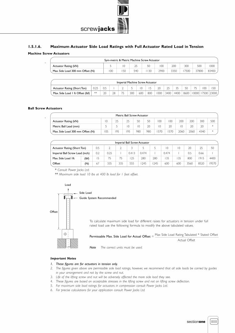
111
screw jacks
sectionone
1.5.1.6. Maximum Actuator Side Load Ratings with Full Actuator Rated Load in Tension
Machine Screw Actuators
Ball Screw Actuators
* Consult Power Jacks Ltd.** Maximum side load 10 lbs at 400 lb load for 1 foot offset.
To calculate maximum side load for different raises for actuators in tension under fullrated load use the following formula to modify the above tabulated values.
Permissable Max. Side Load for Actual Offset =
Note The correct units must be used.
Sym-metric & Metric Machine Screw Actuator
Actuator Rating (kN)
Max. Side Load 300 mm Offset (N)
1000
83400
500
37800
300
17500
200
3350
100
2900
50
1130
25
540
10
150
5
100
Imperial Machine Screw Actuator
Actuator Rating (Short Ton)
Max. Side Load 1 ft Offset (lbf)
0.25
**
0.5
20
1
28
2
75
5
300
10
600
15
800
20
1000
25
3400
35
4400
50
8600
75
10000
100
17500
150
23000
Metric Ball Screw Actuator
Actuator Rating (kN)
Metric Ball Lead (mm)
Max. Side Load 300 mm Offset (N)
25
5
195
10
5
105
25
10
195
50
10
980
50
20
980
100
10
1570
100
20
1570
200
10
2060
200
20
2060
300
20
4340
500
*
*
Imperial Ball Screw Actuator
Actuator Rating (Short Ton)
Imperial Ball Screw Lead (inch)
Max. Side Load 1ft
Offset
0.5
0.2
15
67
(lbf)
(N)
2
0.25
75
335
2
1
75
335
3
0.413
125
555
5
0.474
280
1245
5
1
280
1245
10
0.474
135
600
10
1
135
600
20
0.5
800
3560
25
0.66
1915
8520
50
1
4400
19570
Load
Side Load
Guide System Recommended
Offset
Important Notes
1. These figures are for actuators in tension only.2. The figures given above are permissible side load ratings, however, we recommend that all side loads be carried by guides
in your arrangement and not by the screw and nut.3. Life of the lifting screw and nut will be adversely affected the more side load they see.4. These figures are based on acceptable stresses in the lifting screw and not on lifting screw deflection.5. For maximum side load ratings for actuators in compression consult Power Jacks Ltd.6. For precise calculations for your application consult Power Jacks Ltd.
Max Side Load Rating Tabulated * Stated Offset
Actual Offset

112
screw jacks
sectionone
1.5.1.7. Radial Loads on Actuator Worm Shaft
For applications where an actuator is belt/chain driven, a calculation must be made to determine the radial force (FR) and compared to
the allowable radial load exerted on the worm shaft, that must not exceed those tabulated below. The values below are maximumvalues for the actuators at rated load regardless of worm speed or load direction and the radial load applied midway along the key ofthe worm shaft. For all applications the sprocket, gear etc. Should be positioned as close as possible to the actuator housing in order toreduce bearing loads and shaft stresses, and to prolong life.
Radial Force, FR =
where FR = Radial load (N).
T = torque applied to the actuators input shaft (Nm).
K = factor from table below.
D = p.c.d. in mm of gear, sprocket.
FR
2000 x T x K
D
Transmission Element Factor K
Chain sprocket
Gears (Spur or helical pinion)
V-Belt pulley
Flatbelt pulley
1
1.25
1.5
2.0
Sym-metric Machine Screw Actuators
Actuator Rating (kN)
Radial Load (N)
25
440
50
1100
100
1200
200
1600
Metric Machine Screw & Ball Screw Actuators
Actuator Rating (kN)
Radial Load (N)
5
180
10
325
25
380
50
740
100
1000
200
1600
300
2170
500
2190
1000
2220
Imperial Ball Screw Actuators
Model Number
Actuator Rating(Short Ton)
Lead (inches)
Radial Load
28631
0.5
0.2
27
120
2802
2
0.25
47
210
28021
2
1
42
185
28003
3
0.413
51
225
2805
5
0.474
96
425
28051
5
1
90
400
2810
10
0.474
280
1245
28101
10
1
270
1200
2820
20
0.5
270
1200
2825
25
0.66
475
2110
2860
50
1
235
1045
(lbf)
(N)

113
screw jacks
sectionone
1.5.1.8. Actuator Accuracy
1.5.1.8.1. Axial Backlash Ratings
1.5.1.8.1.1. Sym-Metric, Metric and Imperial Machine Screw Actuators
Note 1. The lifting screw backlash will increase during operation due to wear of threads in the nut.2. Axial play can be reduced by altering the load bearings preload to eliminate bearing play or by specifying an
actuator with the Anti-Backlash Feature.3. For exact backlash ratings for an individual unit consult Power Jacks.
1.5.1.8.1.2. Anti-Backlash OptionThis unit can be adjusted for screw thread and bearing clearances to a minimum of 0.025 mm (0.001”). Some clearances must bemaintained to keep torque requirements within reason and to provide adequate space for a lubrication film to form.
1.5.1.8.1.3. Ball Screw Actuators
Note 1. For exact backlash ratings for an individual unit consult Power Jacks.2. Ball nuts can be supplied with zero backlash or with adjustable backlash via a special twin nut assembly (twin
nut assembly for rotating screw units only). Consult Power Jacks for details.3. Altering the load bearings preload to eliminate bearing play can reduce axial play.4. There is no Anti-Backlash nut feature for the gear sets of these actuators.
1.5.1.8.2. Pitch Deviation of Lifting Screw
Note 1. Pitch deviation is cumulative and NOT detrimental to the operation of the actuator.2. The Lifting screws are manufactured from material with a straightness tolerance of 0.2 mm per metre.3. Pitch deviation is related to the cutting machines tolerance and the material used.
Component
Lifting Screw and Nut
Load Bearings
Total
0.12 mm → 0.2 mm (0.005” → 0.008”)
0.00 mm → 0.03 mm (0.000” → 0.001”)
0.12 mm → 0.23 mm (0.005” → 0.009”)
Normal Backlash
Component
Ball Track and Ball Nut
Load Bearings
Total
0.05 mm → 0.15 mm (0.002” → 0.006”)
0.00 mm → 0.03 mm (0.000” → 0.001”)
0.05 mm → 0.18 mm (0.002” → 0.007”)
Normal Backlash
0.05 mm → 0.33 mm (0.002” → 0.013”)
0.05 mm → 0.075 mm (0.002” → 0.003”)
0.10 mm → 0.405 mm (0.004” → 0.017”)
Normal Backlash
Actuator Type Metric Imperial
Lifting Screw
Machine Screw
Ball Screw
0.05 mm → 0.25 mm per 300 mm
0.002” → 0.010” per foot
0.025 mm → 0.050 mm per 300 mm (DIN Class 5,7)
± 0.009” per foot (± 0.229 mm per 300 mm)
Metric
Imperial
Metric
Imperial
Pitch Deviation

114
screw jacks
sectionone
1.5.1.8.3. Lateral Movement Ratings
1.5.1.8.3.1. Sym-metric Machine Screw Actuators
1.5.1.8.3.2. Metric Machine Screw Actuators
1.5.1.8.3.3. Imperial Machine Screw Actuators (1800 & 9000 Series)
Notes 1. Values quoted above are the maximum expected lateral movement for the given raise and actuator model.2. Does not allow for possible deflection due to side loads.3. Lateral movements are for information only. For best results we recommend guides where possible.4. Lateral movements will be reduced if the actuator is fitted with secondary guides (standard option
for Sym-metric and Metric actuators).5. The above movements apply to machine screw actuators only and not ball screw actuators. Permitting
lateral movement on the ball screw actuators under load will exert side thrust on the ball screw and ballnut, and will be detrimental to the ball screw and nut life. Ball screw applications should be guided to ensure a minimum of lateral movement.
6. Where lateral movement is critical consult Power Jacks for exact values for the application.
Raise (mm) 25 kN 50 kN 100 kN 200 kN
100
200
300
400
500
600
700
800
900
1000
0.7
1.1
1.6
2.0
2.5
2.9
3.3
3.8
4.2
4.7
0.9
1.4
2.0
2.5
3.0
3.5
4.1
4.6
5.1
5.6
0.8
1.3
1.7
2.2
2.6
3.1
3.5
4.0
4.4
4.9
0.4
0.6
0.8
1.0
1.2
1.5
1.7
1.9
2.1
2.3
Raise (mm) 5 kN 10 kN 25 kN 50 kN
100
200
300
400
500
600
700
800
900
1000
0.7
1.3
1.9
2.5
3.1
3.7
4.3
4.8
5.4
6.0
0.6
1.1
1.5
2.0
2.4
2.8
3.3
3.7
4.2
4.6
0.8
1.4
1.9
2.5
3.1
3.6
4.2
4.8
5.3
5.9
1.0
1.7
2.3
2.9
3.6
4.2
4.8
5.5
6.1
6.7
100 kN 200 kN 300 kN 500 kN
1.0
1.7
2.3
2.9
3.6
4.2
4.8
5.5
6.1
6.7
0.4
0.7
0.9
1.2
1.4
1.6
1.9
2.1
2.4
2.6
0.4
0.6
0.8
1.0
1.2
1.4
1.6
1.8
1.9
2.1
0.7
1.0
1.3
1.7
2.0
2.3
2.6
2.9
3.2
3.6
1000 kN
0.7
1.0
1.3
1.6
1.9
2.2
2.4
2.7
3.0
3.3
Raise (inch) 2555
3
6
9
12
15
18
21
24
.040
.085
.090
.115
.140
.165
.190
.215
2625
.050
.075
.105
.135
.165
.195
.225
.225
2501
.020
.030
.040
.050
.060
.070
.080
.090
1802
.020
.035
.055
.070
.090
.100
.120
.135
9002
.020
.035
.055
.070
.090
.100
.120
.135
1805
.030
.050
.070
.090
.110
.130
.150
.170
1810
.025
.040
.055
.070
.085
.100
.115
.135
1815
.030
.045
.065
.080
.100
.120
.133
.150
1820
.025
.040
.050
.070
.080
.095
.105
.125
1825
.035
.060
.085
.105
.130
.155
.175
.200
9035
.040
.050
.060
.070
.080
.090
.100
.110
1850
.060
.090
.120
.150
.180
.215
.245
.275
9075
.050
.060
.070
.080
.090
.100
.110
.120
1899
.050
.060
.070
.080
.090
.100
.110
.120
18150
.050
.060
.070
.080
.090
.100
.110
.120
2250
.090
.100
.110
.120
.130
.140
.150
.160

115
screw jacks
sectionone
1.5.2. Actuators Product Operation
1.5.2.1. Actuators
1.5.2.1.1. Actuator Mechanical Performance
1.5.2.1.1.1. Lifting Torque RequiredThe input torque for a single actuator depends on the load, the worm gear ratio, type of screw (machine cut or ball screw) and thepitch of the lifting screw. Torque values are listed in the individual product specification charts based on capacity loads. For loads from25% to 100% of actuator model capacity, torque requirements are approximately proportional to the load.
1.5.2.1.1.2. Actuator Operating Input SpeedThe input power to these actuators should not exceed the power rating shown in the specifications table. Maximum rpm should notexceed 1800 (sym-metric actuators can go up to 3000 rpm). We cannot accept responsibility for the overheating and rapid wear thatmay occur should these limits be exceeded. Power increases in direct proportion to the speed, and the motor size will be out ofproportion to the actuator model design rating should the speed become excessively high. When selecting the maximum permissiblespeed for an actuating arrangement, always check to see that the power rating of the actuator model is not exceeded.
1.5.2.1.1.3. Actuator EfficiencyActuator model efficiencies are listed in the individual product specification charts.
1.5.2.1.1.4. Worm Gear Actuator LifeThe life expectancy of a machine screw actuator screw, nut and worm gear set varies considerably due to extent of lubrication, abrasiveor chemical action, overloading, excessive heat, improper maintenance, etc. For life calculations consult Power Jacks Ltd.
1.5.2.1.1.5. Torque of a Rotating Screw Actuator and a Standard UnitThe input torque, as well as the efficiency and side load ratings, are the same for both translating screw and rotating screw actuators.
1.5.2.1.1.6. Shock Loads on an ActuatorShock loads should be eliminated or reduced to a minimum, if they cannot be avoided, the actuator model selected should be rated attwice the required static load. For severe shock load applications, using the Sym-metric, Metric and Imperial actuators, the load bearingsshould be replaced with heat-treated steel thrust rings which is an option available from Power Jacks. Note this will increase the inputtorque by approximately 100 percent.
1.5.2.1.1.7. Backlash in an Actuator UnitMachine screw actuators, machine screw actuators with anti-backlash and ball screw actuators must be considered separately, as thenormal backlash will vary due to different constructions.
1.5.2.1.1.7.1. Machine Screw ActuatorsMachine Screw Actuators have backlash due not only to normal manufacturing tolerances, but to the fact that we must have someclearances to prevent binding and galling when the actuator unit is under load (refer 1.5.1.8.). Usually, the backlash is not a problemunless the load on the actuator unit changes between compression and tension. If a problem does exist, then a unit with the anti-backlash feature should be considered.

116
screw jacks
sectionone
1.5.2.1.1.7.2. Anti-Backlash Actuator FeatureWhen the screw (1) is under a compression load, the bottom of its thread surfaces are supportedby the top thread surfaces of the worm gear (2) at point (A). The anti-backlash nut (3), being pinnedto the worm gear and floating on these pins and being adjusted downward by the shell cap, forcesits bottom thread surfaces against the upper thread surfaces of the lifting screw at point (B). Thus,backlash between worm gear threads is reduced to a regulated minimum (refer 1.5.1.8.).
When wear occurs in the worm gear threads and on the load carrying surfaces of the lifting screwthread, the load carrying thickness of the worm gear thread will be reduced. This wear will create agap at point (B) and provide backlash equal to the wear on the threads.
Under compression load, the lifting screw will no longer be in contact with the lower thread surfaceof the anti-backlash nut. Under this condition, backlash will be present when a tension load is applied.The anti-backlash feature can be maintained simply by adjusting the shell cap until the desiredamount of backlash is achieved.
To avoid binding and excessive wear do not adjust lifting screw backlash to less than 0.013mm(0.0005”).
This will reduce the calculated separation (C) between the anti-backlash nut and worm gear and willreduce the back lash between the worm gear threads and the lifting screw to the desired minimumvalue.
When separation (C) has been reduced to zero, wear has taken place. Replace the worm gear (2) atthis point. This feature acts as a built in safety device which can be used to provide wear indicationfor critical applications.
1.5.2.1.1.7.3. Ball Screw ActuatorsBall Screw Actuators do not have an anti-backlash option similar to the machine screw actuators. Instead for zero or reduced axial playballscrew actuators can be ordered with a pre-loaded ball nut (refer 13.1.1.2.).
1.5.2.1.1.8. Actuator Self-LockingThe following actuator models are considered not to be self-locking; all Metric and Imperial ball screw actuators, the 2555 (1/4 ton),the 2625 (1/2 ton), the 2501 (1-ton), in some cases the 1802 & 9002 (2 ton) units, the 1805 (5 ton) unit, the 1810 (10 ton) unitand the 1815 (15 ton) unit. The 24:1 and 25:1 ratios are self-locking in most cases. All actuators with double start lifting screws areconsidered not to be self-locking. Units considered not self-locking will require a brake or other holding device (refer 1.1.3.2.7.).If vibration conditions exist, refer to section 1.5.2.1.4.5. For detailed advice and analysis consult Power Jacks.
1.5.2.1.2. Lifting Screw
1.5.2.1.2.1. Lifting Screw OperationWhen an actuator unit is operated, the rotation of the worm shaft causes the worm gear to rotate. The worm gear is threaded toaccommodate the lifting screw thread; as the worm gear turns, the friction forces on the screw thread act to turn the screw also. Thegreater the load on the actuator unit, the greater the tendency of the screw to turn. It is obvious that if the screw turns with the nut(worm gear), it will not raise the load. In those cases where a single unit is used, and where the load cannot be restrained from turning,it is necessary to key the lifting screw. Lifting screw key torques (refer 1.5.1.5.) must be checked as excessively heavy unguided loadscould break the key.
1.5.2.1.2.2. Keyed Lifting Screw - To Prevent RotationAvailable for all actuators, except for the ball screw. Note the keyway in the screw causes greater than normal wear on the internalthreads of the worm gear. The ball screw actuators cannot be keyed, as the keyway would interrupt the ball track, permitting loss of therecirculating balls.
We recommend the following methods for preventing rotation. For multiple actuator model applications, bolt the lifting screw top platesto the member being lifted. For single actuator unit applications, bolt the lifting screw top plate to the load and ensure the load isguided to prevent rotation. A guided load is recommended as a heavy unguided load could cause key failure. Note as a special designoption a square anti-rotation tube can be fitted to ball screw actuators to prevent rotation (refer 1.3.1.10.). For further details consultPower Jacks Ltd.
2
A
C3
B
TensionLoad
CompressionLoad
Shell Cap
1

117
screw jacks
sectionone
1.5.2.1.2.3. Keyed Lifting Screw For An Inverted ActuatorFor Metric and Imperial actuators the key is mounted in the shell cap, making it necessary to omit the bottom pipe as a standard item.If a dust guard is required, a special adaptor must be attached to permit mounting. Sym-metric actuators can have the key mountedeither side of the gear with a bottom pipe available for both options, as standard.
1.5.2.1.2.4. Lifting Screw Column StrengthThe column strength of a screw is determined by the relationship between the length of the screw and its diameter. Column strengthnomographs are included in this book (refer 1.5.1.1.).
1.5.2.1.2.5. Actuator Side LoadsActuator units are designed primarily to raise and lower loads and any side loads should be avoided. These units will withstand someside loads, depending on diameter of the screw and the extended length of the screw. Where side loads are present, the loads shouldbe guided and the guides, rather than the actuator units, should take the side loads - particularly when long raises are involved. Even asmall side load can exert great force on the housings and bearings and increase the operating torque and reduce the life expectancy.“Side Load Rating Charts” are included in this book (refer 1.5.1.6.)
1.5.2.1.2.6. Maximum Practical Raise or Working StrokeGenerally, standard raises are up to 300mm on 5kN and 500mm on 10 kN on metric screw actuators 12 inches on 1/4 and 1/2 tonmodels and 18 inch on the 2501 (one ton) imperial actuators. Maximum raises available for the larger diameter screws are limited only by the available length of bar stock from suppliers. Practical length will be affected by whether the screw is to be subjected tocompression or tension loads. Depending on diameter the length can be limited due to deformation of material in the machiningprocess or column strength of the screw when subjected to compression loads. Long raise applications should be checked withPower Jacks for the following:
a) Side loads on extended screw (1.5.1.6.)
b) Column strength of screw (1.5.1.1.)
c) Thermal rating of screw and nut (1.5.2.1.3.4.)
We suggest guides be used on all applications. The longer the raise, the more important this becomes.
1.5.2.1.3. Actuator Duty
1.5.2.1.3.1. Allowable Duty Cycle of a Worm Gear ActuatorBecause of the efficiency of conventional metric and imperial worm gear actuators, the duty cycle is intermittent at rated load. Atreduced loading, the duty cycle may be increased. The Sym-metric actuators have higher thermal efficiencies due to their design allowinggenerally 50% higher duty cycles than conventional style actuators. For detailed analysis consult Power Jacks.
1.5.2.1.3.2. Worm Gear Actuator Suitability for High Temperature OperationThe actuator is normally suitable for operation at ambient temperatures of up to 90ºC. Operations above 90ºC will require speciallubricants. For temperatures above 90ºC, the life of even special lubricants is limited. Therefore consult Power Jacks on your application.
For temperatures above 90ºC, advise Power Jacks of full particulars of the duration of such temperatures. In some cases, it may benecessary to furnish an unlubricated unit, then the customer will supply the lubricant of his own choice. We suggest that a lubricantmanufacturer be consulted for type of grease and lubrication schedule. As a general rule, the actuator unit should be shielded to keepambient temperatures to 90ºC or less.
Seals for temperatures above 120ºC are very expensive. Instead, we should substitute bronze bushings for seals in these cases. If bellowsboots are used, special materials will be required for temperatures above 90ºC.

118
screw jacks
sectionone
1.5.2.1.3.3. Actuator Suitability for Low Temperature OperationWith the standard lubricant and materials of construction, the actuator is suitable for use at sustained temperatures of -20ºC. Below -20ºC, low temperature lubricant should be used. Also, at temperatures below -20ºC, if there is any possibility of shock loading, specialmaterials may be required due to notch sensitivity of the standard materials at lower temperatures. Power Jacks application engineersmust be consulted in these instances for a recommendation.
Actuators with standard material of construction and lubrication may be safely stored at temperatures as low as -55ºC.
1.5.2.1.3.4. Thermal/Heat Build-Up in an Actuator UnitThe duty cycle, the length of the screw, the magnitude of the load, and the efficiency of the actuator unit all have a direct influence onthe amount of heat generated within the actuator model. Since most of the power input is used to overcome friction, a large amount ofheat is generated in the worm gear set in both ball screw and machine screw actuator models, and in the lifting screw of machinescrew actuator units. Long lifts can cause serious overheating. Sym-metric actuators have an oil lubricated cubic gearbox housingspecifically designed to dissipate heat more efficiently with increased surface area and mass, allowing increased duty capabilities.
1.5.2.1.3.5. Continuous Duty ActuatorsRecommendation should be obtained from Power Jacks on this type of application and a completed application analysis form submitted.In general, semi-continuous operation can be permitted where load is light as compared to actuator model rated capacity. Units so usedshould be lubricated frequently and protected against dust and dirt. The Sym-metric and 7500 Series, oil-lubricated, high duty cycleactuators, are designed for maximum duty cycles. Special purpose actuators fitted with ball screws may also suit applications, consultPower Jacks.
1.5.2.1.4. Actuator Applications
1.5.2.1.4.1. Bellows Boots for an Inverted Screw ActuatorMetric and Imperial inverted screw actuators with bellows boots must incorporate an allowance in the length of the lifting screw forboth the closed height of the boot and structure thickness. Since we can make no provision for attaching a boot on the underside ofyour structure, we suggest that a circular plate similar to the lifting screw top plate be welded or bolted to the bottom of yourstructure supporting the actuator unit, thereby making it possible to use a standard bellows boot. (refer 1.2.1.8., 1.2.2.8., 1.2.3.7. and1.3.1.3. and 1.3.2.8.).
Sym-metric actuators allow mounting from two sides instead of one and allow mounting on the same side as the bellows boot withonly an access hole required in the structure for the lifting screw and bellows boot.
1.5.2.1.4.2. Actuator used to Pivot a LoadThe actuator can be furnished with a clevis at both ends. The bottom clevis is welded to the bottom end of an extra strong pipe whichis threaded into the base of the actuator and welded. This bottom pipe still performs its primary function of encasing the lifting screw inits retracted portion. The design of the structure in which this type unit is to be used must be so constructed that the actuator unit canpivot at both ends. Use only direct compression or tension loads, thereby eliminating side load conditions. See the double clevis modelillustrations on the dimensional drawings (refer 1.2.2.10., 1.2.3.5. 1.3.1.5. and 1.3.2.7.).
1.5.2.1.4.3. Actuators used within Rigid Structures or PressesWe recommend that the actuator selected has a greater capacity than the rated capacity of the press or of the load capacity of thestructure. We also recommend that a torque clutch or similar device be used to prevent overloading of the actuator unit. Unless theseprecautions are taken, it is possible to overload the actuator unit without realising it.

119
screw jacks
sectionone
1.5.2.1.4.4. Actuator Drift after Motor Switch OffThe actuator will drift after the motor drive is switched off unless a brake of sufficient capacity is used to prevent it. The amount of driftwill depend upon the load on the actuator unit and the interia of the rotor in the motor. Due to different construction, the ball screwactuator unit must be considered separately; refer 1.1.3.2.7. Machine screw actuators require approximately one-half as much torque tolower the load as they do to raise the load.
For machine screw actuators with no load, the amount of drift will depend upon the size and speed of the motor. For example, a 1500RPM motor directly connected to an actuator unit without a load will give on average 35mm → 60mm drift; a 1000 RPM gear motorwill give about 1/2 as much drift. Note that the drift varies as the square of the velocity (RPM). The drift of the actuator unit screw canbe controlled by using a magnetic brake on the motor.
1.5.2.1.4.5. Actuator Units where Vibration is PresentThe actuators will operate in areas with vibration, however the vibration may cause the lifting screw to creep or inch down under load.For applications involving slight vibration, select the higher of the worm gear ratios. Should considerable vibration be present, use a drivemotor equipped with a magnetic brake which will prevent the actuator from self-lowering.
1.5.2.1.4.6. Stop Discs, Stop Pins or Stop Nuts Used on Actuator UnitsTo prevent over travel of the lifting screw a stop disc, pins or nut can be fitted to an actuator unit that is hand operated. For motordriven units it is possible for the full capacity of the actuator unit or even a greater force (depending on the power of the motor) to beapplied against the stop, thereby jamming so tightly it must be disassembled in order to free it. It is recommended that external stops arefitted where possible, however they must only be used as a last resor t (Note - limit switches are one possible solution to constrainactuator movement safely - consult Power Jacks for system advice). Under ideal conditions where a slip clutch or torque limiting device isused, a stop pin or stop nut may be used - but Power Jacks should be consulted. The stop disc used on the bottom of the lifting screwprevents our ball screw from running out of the ball nut during shipping and handling, thereby preventing loss of the recirculating balls.
1.5.2.2. Actuator Systems
1.5.2.2.1. Multiple Actuator ArrangementsPerhaps the greatest single advantage of Power Jacks actuators is that they can be linked together mechanically, to lift and lower inunison. Typical arrangements involving the actuator units, bevel gear boxes, motors, reducers, shafting and couplings are shown in section1.1.3.2.8.
1.5.2.2.2. Number of Actuators Connected in SeriesThis will be limited by input torque requirements on the first worm shaft in the line. The torque on the worm shaft of thefirst actuator unit should not exceed 300% of its rated full load torque on the machine screw actuators (this does not include the1820 unit).
1.5.2.2.3. Multiple Actuator ArrangementIn addition to the efficiencies of the actuator units and the mitre gearboxes, the efficiency of the actuator multiple-unit arrangementmust be taken into consideration. The arrangement efficiency allows for misalignment due to slight deformation of the structure underload, for the losses in couplings and bearings, and for a normal amount of misalignment in positioning the actuators and gear boxes. Forefficiency values refer 1.1.3.2.8.
1.5.2.2.4. Multiple Actuator Unit Arrangement with a Visual Position Indicator forLifting Screw Position at any Point
A visual position indicator for an actuator system can be provided in several ways, for example:
1. Actuator system with encoder and counter (refer 8.3. and 8.4.)
2. Actuator system with rotary limit switch and position transducer (refer 8.1.2.)
However, it is suggested you consult Power Jacks for recommendations based on your particular application.

120
screw jacks
sectionone
1.5.3. Installation and Maintenance Tips
The following installation and maintenance tips are for the Sym-metric, Metric and Imperial machine screw and ball screw actuatormodels.
General care should be taken to ensure that equipment is sufficient to handle the load.
1. The structure on which the actuator unit is mounted should have ample strength to carry the maximum load, andbe rigid enough to prevent undue deflection or distortion of the actuator unit supporting members.
2. It is essential that the actuator unit be carefully aligned during installation so that the lifting screws are vertically trueand the connecting shafts are exactly in line with the worm shafts. After the actuator unit, shafting, and gear boxesare coupled together, it should be possible to turn the main drive shaft by hand. If there are no signs of binding ormisalignment, the actuating system is then ready for normal operation.
3. The actuator unit should have a greater raise than is needed in the actuator installation. If it is necessary to operatethe actuator at the extreme limits of travel, it should be done with caution.
CAUTION: Do not allow screw travel below catalogue closed height of the actuator unit or serious damage tointernal mechanism may result. Refer to table specifications for closed height of respective units.
4. The input power should not exceed the power rating shown in the specification table. Maximum RPM should notexceed 1800.
5. The lifting screw should not be permitted to accumulate dust and grit on the threads. If possible, lifting screwsshould be returned to closed position when not in use.
6. The ball screws in the ball screw actuator units should be checked periodically for excessive backlash and spalling ofraceways. A periodic check of backlash of the lifting screw thread is recommended to check wear of the worm gearinternal threads on the machine screw actuator models. Backlash in excess of 50% of the thread thickness indicatesthe need to replace the worm gear. (refer 1.5.1.7. and 1.5.2.1.1.7.).
7. Unless otherwise specified, actuator units and gear boxes are shipped packed with grease (refer point 8 for oillubricated standard products) which should be sufficient for one month of normal operation. For normal operation,the actuator units and gear boxes should be lubricated about once a month, using one of the following extremepressure greases or their equivalent:
Shell Alvania WR2
BP Energrease LC2
Castrol Spheerol L-EP2
Mobil Mobilux EP2
For severe conditions, the actuator units should be lubricated more frequently, using one of the above greases (dailyto weekly depending on conditions). If duty is heavy, an automatic lubrication system is strongly recommended. Ifambient temperatures exceed 90ºC (194ºF) consult Power Jacks.
8. Unless otherwise specified, all Sym-metric Actuators have oil filled gear boxes which should be sufficient for normaloperation. Under normal operation, the actuator units should have oil levels checked regularly, using one of thefollowing premium gear oils or their equivalent:
Sym-metric Actuator
BP Energol GR-XP150
Shell OMALA Oil 150
Castrol Alpha SP150
Mobil Gear Oil 629
9. On ball screw actuator model applications, periodically lubricate the exposed ball screw grooves with a clothdampened with a good grade 10W30 oil for most applications. An instrument grade oil should be used in dirtyand heavy duty environments, and bearing grease for environments at extremely high temperatures. Extremetemperature and other environmental conditions should be referred to Power Jacks for recommended lubricatingprocedures.
CAUTION: Where ball screws are not protected from airborne dirt, dust, etc., bellows boots should be used.Inspect frequently at regular intervals to be certain a lubricating film is present. Ball screws shouldnever be run dry.
10. Due to the high efficiency of the ball screw actuator design, a brake must be used in conjunction with motorselected to position the actuator unit (refer 1.1.3.2.7. and 1.5.2.1.1.8.)

2. linear actuators (electro mechanical)
Power Jacks Rolaram Linear Actuators with Ball Screw
Medium load, high duty, high speed, high accuracyDynamic load ratings up to 65 kNLinear speeds up to 7000 mm/min3 Phase AC, 1 Phase AC and DC types
Section 2.2. - Rolaram Linear ActuatorsRolaram® Linear Actuators Ball Screw4 kN to 65k N
Power Jacks EMA Linear Actuators
Machine Screw and Ball ScrewLow load, medium duty, high speedDynamic load ratings up to 10 kNLinear speeds up to 5500 mm/min3 Phase AC, 1 Phase AC and DC types
Section 2.1. - EMA Linear ActuatorsEMA Series ActuatorsAC and DC 2.5 kN to 10kN
Power Jacks Rolaram Linear Actuators with Roller Screw
High load, high duty, high speed, very high accuracyDynamic load ratings up to 400 kNLinear speeds up to 7000 mm/min3 Phase AC, 1 Phase AC and DC types
Section 2.2. - Rolaram Linear ActuatorsRolaram® Linear Actuators Roller Screw4 kN to 400 kN
Power Jacks Special Linear Actuators
Special designs for EMA or Rolaram ActuatorsMachine Screw, Ball Screw or Roller ScrewDynamic load ratings up to 1000 kNLinear speeds up to 10000 mm/min3 Phase AC, 1 Phase AC and DC types
Section 2.1. and 2.2. - Special Linear ActuatorsSpecial Custom Designed Linear Actuators
POWER JACKSGroupmanufacturers of precision screw jacks, actuators and gearboxes

1
linear actuators
sectiontwo
Contents
2. Linear Actuators (Electro-Actuators)
2.1. EMA Linear Actuators 22.1.1. Overview of EMA Linear Actuator Range 2
2.1.2. EMA Typical Applications 3
2.1.3. Working Applications for EMA Actuators 4
2.1.4. Product Code for EMA Actuators 5
2.1.5. EMA Linear Actuator Performance Data 6
2.1.6. EMA Linear Actuator Dimensions 8
2.1.7. Accessories and Options for EMA Actuators 13
2.1.8. Installation and Maintenance Tips for EMA Actuators 14

2
linear actuators
sectiontwo
2.1. EMA Linear Actuators
2.1.1. Overview of EMA Linear Actuator Range
2.1.1.1. What is EMA Linear Actuator?EMA is an abbreviation for Electro Mechanical Actuator, which consists of either a trapezoidal or ball lead screw, driven by an electricmotor through spiroid gearing. The screw converts the rotary motion into linear movement. As the screw rotates, the nut extends andretracts the ram, which is attached to the load.
2.1.1.2. The EMA Linear Actuator RangeThere are 3 standard EMA models, all available in a right-angle drive configuration.
• Intermittent model, incorporating a trapezoidal screw.
• Continuous model, incorporating a ball screw
• High Speed Continuous model, incorporating a ball screw.
Where the standard range does not meet the application specification, special actuators can be designed to meet customers’ specificrequirements.
2.1.1.3. Dynamic Load Capacity and SpeedThe dynamic load capacity range is up to 10 kN. A defined range of linear speeds from 135 mm/minute to 5510 mm/minute is available.The speed range is achieved by using a combination of gearbox ratios, screw leads and standard motor speeds.
2.1.1.4. DrivesAs standard, the units are available with 240v/415v AC or 24v DC motors, with or without a brake. The type of motors required isdependent on the customer’s application. The motors are mounted to the actuator on a 63C Face Flange Mounting.
2.1.1.5 StrokeEach model can be provided with a stroke length up to the maximum, in compression, shown in the Technical Charts. The stroke isdefined by the customer. For a tensile load, greater maximum strokes can be accommodated, depending on the linear speed. Where thestroke required exceeds the maximum shown, or there is a high static load, please contact our Technical Sales Department.
2.1.1.6. Standard Features• Choice of AC or DC motor drives.
• Choice of end fittings: clevis, fork clevis,top plate or screwed end.
• Trunnion Mounting.
• Limit Switches.
2.1.1.7. Emergency Overload ClutchThe emergency overload clutch is a device, which is mounted on the actuator ram, which will slip when the torque to drive the loadexceeds the limit set. If the load is axially locked, or if a torque greater than the clutch setting is required to move the load, the clutchwill disengage the load from the ram and prevent the motor from overloading the actuator components. Please note that the clutch isan emergency device and should not be used for reversing the actuator direction.
2.1.1.8. Limit SwitchesLimit switches are fitted to provide end of stroke or ultimate over travel safety. They are mounted on the outer tube of the actuatorand are tripped by a collar on the ram. They are set at a fixed length defined by the customer (see dimensional page for details).Adjustable Limit Switches can be provided on request, consult Power Jacks.
2.1.1.9. Guiding the LoadSide loads on the actuator ram should be avoided by ensuring that the load is guided. The load guide mechanism should resist thetorque developed at the ram by the screw mechanism. A guided ram can be supplied on request, which utilises a keyway in the innerram, eliminates the need for torsional restraint and therefore allows flexibility in the choice of end fitting.
2.1.1.10. ConstructionAll units are constructed and finished to suit industrial operating conditions. The actuator gearbox and outer tube are either aluminiumor plated for protection and the ram is zinc plated steel. The actuator is sealed at the ram.

3
linear actuators
sectiontwo
2.1.2. EMA Typical Applications
2.1.2.1. Tilt/PivotEMA Linear Actuators can be used to tilt objects, fixed at one end, up to 180°from their starting positions. The extension and retraction of the actuator causesthe object to pivot about its stationary end.
2.1.2.2. Lift/LowerEMA Linear actuators can handle any lifting and lowering application up to 10kN.As the translating tube of the actuator extends and retracts, the object that theactuator is attached to is raised and lowered at a constant speed.
2.1.2.3. PositionWhen an application requires periodic adjustment to the position ofan object or objects, EMA linear actuators provide the solution. Themotion of the actuator allows the operator to position an object bysimply pushing a button.
2.1.2.4. Roll/SlideWhen it is necessary to roll or slide an object or a mechanical assembly intoposition, an EMA linear actuator is the answer. The movement of the actuatorcauses the clamping, rolling or sliding of the desired object.
2.1.2.5. Open/CloseAn EMA linear actuator mounted on a door, gate or valve allows opening and closingoperations on either a timed, or on-demand basis. As the actuator retracts the gate isopened at a steady rate; the extension of the actuator returns the gate to a closedposition.
2.1.2.6. TensionEMA linear actuators offer a perfect solution for applications in which tension on aconveyor or webb must be maintained and adjusted. An actuator mounted on aframe or roller extends and retracts to control the tension in the system.
2.1.2.7. Lock/UnlockFor moving a locking device such as a pin in and out of retaining slot, EMA linearactuators provides the perfect solution. The motion of the actuator allows theoperator to lock and unlock the device smoothly and safely by the touch of abutton. Extend and retract limit switches on the actuator can be used as lock/unlock signals for a machines control system.

4
linear actuators
sectiontwo
2.1.3. Working Applications for EMA Actuators
Application Actuation of the rear door of the British Army armoured personnelvehicle. The door weights 240 kg, but at compound angles of 30o, canweigh up to 2.6 tonnes.
Product One Continuous, 5 kN, 24v DC actuator, which is suppressed to avoidradio interference. The actuator can be submersed in water and has tobe able to operate immediately whilst the vehicle is out of the water.
Application To lower the cradle and raise the feed hopper on a granulator. Thegranulator is used in the plastics, rubber and security disintegrationindustries.
Product Two intermittent, 5 kN, 240v AC actuators on each granulator. One at280 mm stroke lowers the cradle and the other at 520 mm strokeraises the hopper.
Application To displace via tilt and slew motions, the slave arm relative to the masterarm, on manipulators for handling radioactive material. The actuators alsoact as load bearing struts, carrying the full reaction loads.
Product Two Continuous, 2.5 kN and 5 kN. DC actuators on each manipulator.
Application Conveyor belt tracking, mainly for the food industry. The actuator moveswhen adjustment is required, to centralize the conveyor belt, ensuringlonger life of the belt and reducing production downtime.
Product One Continuous, 5 kN, 240v AC actuator is fitted onto each trackerunit.
Application Pay off and take up cable/wire machine. The actuators operatecontinuously, providing adjustment to ensure even winding onto thedrums.
Product Two Intermittent, 2.5 kN, 415v AC actuators are fitted onto eachmachine.

5
linear actuators
sectiontwo
(1) (2) (3)
-
(4) (5)
--
(7)
--
(8)
-
(6)
-
(9) (10) (11)
-- -
(1) Actuator ModelI - IntermittentC - ContinuousH - High Speed Continuous
(2) Dynamic Load Capacity02 - 250 kg05 - 500 kg10 - 1000 kg
(3) Linear SpeedThis is shown as a 4 figure coderefer to Technical Charts 2.1.5.
(4) Mountings1 - Version 12 - Version 23 - Version 34 - Version 4The position of mounting versions3 and 4 is variable and should bespecified by the customer at thetime of ordering.
(5) BrakeB - Brake MotorN - Non Brake Motor
(6) Motor Type240 - 240v AC, 1 Phase415 - 415v AC, 3 Phase024 - 24v DC
(7) End FittingC - Clevis EndF - Fork ClevisT - Top PlateS - Screwed End
(8) StrokeA 4 figure code to representthe required stroke in mm.
(9) Emergency Overload Clutch1 - Clutch2 - No Clutch
(10) Limit SwitchesL - Limit SwitchesN - No Limit Switches
(11) Special Feature(s)N - No Special FeatureS - Customer to advise feature(s)
(1)
1 0 5 0 6 8 5 4 1 5 C 0 1 L N0 3 01 B
(2) (3)
-
(4) (5)
--
(7)
--
(8)
-
(6)
-
(9) (10) (11)
-- -
(1) Intermittent Actuator(2) 500 kg Capacity(3) Linear Speed of 685 mm/minute.(4) Mounting Version 1(5) Brake Motor
(6) 415v AC Motor, 3 Phase(7) Clevis End Fitting(8) 300 mm Stroke(9) With Clutch
(10) With Limit Switches(11) Without Special Features
Example Part Number
Notes: 1. Where a special feature is required, the customer should please provide a description and/or drawing of the special feature.
2.1.4. Product Code for EMA Actuators
The product code for Electro Mechanical Actuators (EMAs) is of the following form:
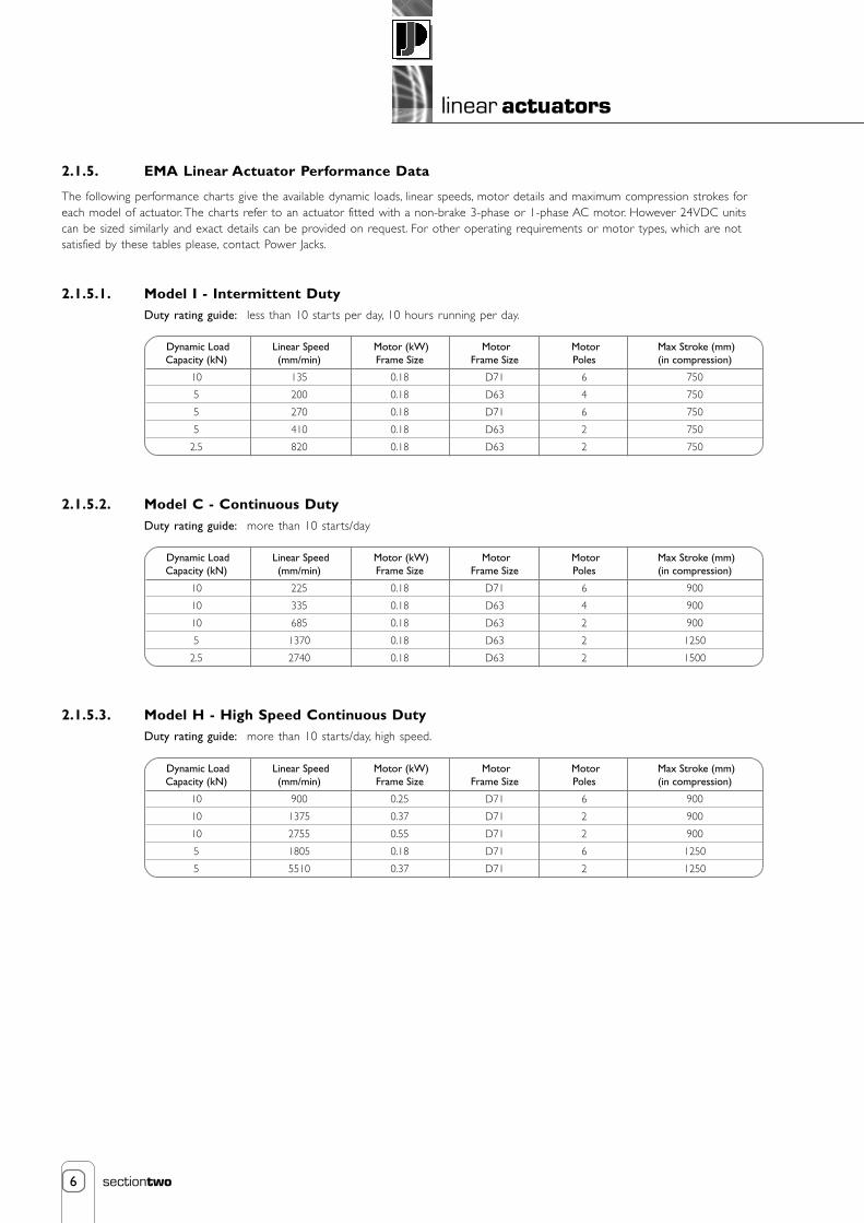
6
linear actuators
sectiontwo
2.1.5. EMA Linear Actuator Performance Data
The following performance charts give the available dynamic loads, linear speeds, motor details and maximum compression strokes foreach model of actuator. The charts refer to an actuator fitted with a non-brake 3-phase or 1-phase AC motor. However 24VDC unitscan be sized similarly and exact details can be provided on request. For other operating requirements or motor types, which are notsatisfied by these tables please, contact Power Jacks.
2.1.5.1. Model I - Intermittent DutyDuty rating guide: less than 10 starts per day, 10 hours running per day.
2.1.5.2. Model C - Continuous DutyDuty rating guide: more than 10 starts/day
2.1.5.3. Model H - High Speed Continuous DutyDuty rating guide: more than 10 starts/day, high speed.
Dynamic LoadCapacity (kN)
10
5
5
5
2.5
Linear Speed(mm/min)
135
200
270
410
820
Motor (kW)Frame Size
0.18
0.18
0.18
0.18
0.18
MotorFrame Size
D71
D63
D71
D63
D63
Max Stroke (mm)(in compression)
750
750
750
750
750
MotorPoles
6
4
6
2
2
Dynamic LoadCapacity (kN)
10
10
10
5
2.5
Linear Speed(mm/min)
225
335
685
1370
2740
Motor (kW)Frame Size
0.18
0.18
0.18
0.18
0.18
MotorFrame Size
D71
D63
D63
D63
D63
Max Stroke (mm)(in compression)
900
900
900
1250
1500
MotorPoles
6
4
2
2
2
Dynamic LoadCapacity (kN)
10
10
10
5
5
Linear Speed(mm/min)
900
1375
2755
1805
5510
Motor (kW)Frame Size
0.25
0.37
0.55
0.18
0.37
MotorFrame Size
D71
D71
D71
D71
D71
Max Stroke (mm)(in compression)
900
900
900
1250
1250
MotorPoles
6
2
2
6
2

7
linear actuators
sectiontwo
2.1.5.4. Motor TypesAs standard, the units are available with 240V / 415VAC 3phase or 240VAC 1 phase or 24VDC motors, with or without a brake. Thetype of motors required is dependent on the customer’s application. The motors are mounted to the actuator on an IEC 63C FaceFlange Mounting.
2.1.5.5. EMA Actuator Weight
2.1.5.6. Operating EnvironmentThe standard operating environment is given below for hostile or hazardous operating environments please consult Power Jacks.
2.1.5.6.1. EnclosureOverall actuator enclosure is IP54 as standard. IP55, 56 and 65 are available on request consult Power Jacks for advise.
2.1.5.6.2. Normal Operating TemperatureNormal operating temperatures are from -10°C to +50°C.
Please contact Power Jacks to discuss hostile or hazardous operating environments.
Item
Voltage
Motor Design
Frame Type
Enclosure (std)
Options
Brake
Enclosure
Encoder
Forced Ventilation
Other
3 Phase
220→240/380→415 VAC
Induction
IEC, 63C Face
IP54
3ph AC, 1ph AC or DC
IP55, 56, 65
Available
Available
Inverter Rated
1 Phase
220→240 VAC
Capacitor Start/Induction Run orCapacitor Start/Capacitor Run
IEC, 63C Face
IP54
1ph AC or DC
IP55
Available
-
-
24 VDC
24 VDC
Permanent Magnet
IEC, 63C Face
IP54
DC
IP55
Available
Available
12, 48 VDC
Motor Type
Model
I
C
H
Basic Weight (kg)
9
10
12
Weight (kg) per 100 mm Stroke
0.69
1.3
1.3

8
linear actuators
sectiontwo
2.1.6. EMA Linear Actuator Dimensions
2.1.6.1. EMA Linear Actuator Arrangements
Trunnion Mount
Top Plate
ForkEnd
ClevisEnd
Standard Rear Clevis
Rear Clevis at 90o

9
linear actuators
sectiontwo
2.1.6.2. Model I - Intermittent Duty
2.1.6.2.1. Model I - WITH Emergency Overload CLUTCH
2.1.6.2.2. Model I - NO Emergency Overload CLUTCH
Stroke + 2
16
60 50.8
44
Stroke + 175 with Clutch without SwitchesStroke + 187 with Clutch with Switches
33
46
14
M12
Ø38
Ø50
ExtendedSwitch Retracted
Switch
57
30
LimitSwitch
Ø13.10Ø13.00
R16
184
with
out
Brak
e28
3 w
ith B
rake
Ø125
Actuator shown with 3 phase ACinduction motor other motorsavailable on request
19.0018.90
89
15.4
37
Stroke + 2
16
60 50.8
44
Stroke + 149.5 without SwitchesStroke + 161.5 with Switches
46
14
M12
Ø35
Ø50
ExtendedSwitch Retracted
Switch
57
30
LimitSwitch
Ø13.10Ø13.00
R16
184
with
out
Brak
e28
3 w
ith B
rake
Ø125
Actuator shown with 3 phase ACinduction motor other motorsavailable on request
19.0018.90
89
15.4
37
12
Note: 1. Dimensions subject to change without notive.2. All dimensions in millimetres (mm) unless otherwise stated.

10
linear actuators
sectiontwo
2.1.6.3. Model C - Continuous Duty
2.1.6.3.1. Model C - WITH Emergency Overload CLUTCH
2.1.6.3.2. Model C - NO Emergency Overload CLUTCH
Stroke + 5
16
70 50.844
Stroke + 238 with Clutch without SwitchesStroke + 252 with Clutch with Switches
46
46
14
M12
Ø50
Ø76
ExtendedSwitch Retracted
Switch
57
30
LimitSwitch
Ø13.10Ø13.00
R16
184
with
out
Brak
e28
3 w
ith B
rake
Ø125
Actuator shown with 3 phase ACinduction motor other motorsavailable on request
19.0018.90
101
15.4
37
Stroke + 5
16
70 50.844
Stroke + 210 without SwitchesStroke + 224 with Switches
46
14
M12
Ø76
Ø50
ExtendedSwitch Retracted
Switch
57
30
LimitSwitch
Ø13.10Ø13.00
R16
184
with
out
Brak
e28
3 w
ith B
rake
Ø125
Actuator shown with 3 phase ACinduction motor other motorsavailable on request
19.0018.90
101
15.4
37
18
Note: 1. Dimensions subject to change without notive.2. All dimensions in millimetres (mm) unless otherwise stated.
Ø38

11
linear actuators
sectiontwo
2.1.6.4. Model H - High Speed Continuous Duty
2.1.6.4.1. Model H - WITH Emergency Overload CLUTCH
2.1.6.4.2. Model H - NO Emergency Overload CLUTCH
Stroke + 5
16
94 8078
Stroke + 310 with Clutch without SwitchesStroke + 345 with Clutch with Switches
44
55
25
M20
Ø76
ExtendedSwitch Retracted
Switch83
30
LimitSwitch
Ø20.021Ø20.000
208
with
out
Brak
e26
3 w
ith B
rake
Ø140
Actuator shown with 3 phase ACinduction motor other motorsavailable on request
24.0023.98
101
25
55
Ø55
Stroke + 5
16
94 8078
Stroke + 274 without SwitchesStroke + 309 with Switches
55
25
M20
Ø76
ExtendedSwitch Retracted
Switch83
30
LimitSwitch
Ø20.021Ø20.000
208
with
out
Brak
e26
3 w
ith B
rake
Ø140
Actuator shown with 3 phase ACinduction motor other motorsavailable on request
24.0023.98
101
25
55
25
Ø60
Note: 1. Dimensions subject to change without notive.2. All dimensions in millimetres (mm) unless otherwise stated.

12
linear actuators
sectiontwo
C
A
BD
ØE
GH
G ØK
JF
L
ØQMN
ØP
ØR
Model
I
C
H
A
26
26
41
B
39
39
65
C
25
25
35
D
19
19
30
E
13.02713.000
13.02713.000
20.03320.000
M
25
25
30
N
10
10
12
P
80
80
100
Q
11
11
13.5
R
55
55
70
F
62
62
105
G
24
24
40
H
12.1512.33
12.1512.33
20.1620.37
J
24
24
40
Clevis End Top PlateFork Clevis
K
12.00012.043
12.00012.043
20.00020.052
L
48
48
80
Clevis End Fork Clevis Top Plate
Model
I
C
H
S
11.9911.96
14.9914.96
14.9914.96
T
70
100
100
U
110
140
140
See Note
300
ØS
Version 1
TU ØS
TU
Version 2 Version 3 Version 4
Alternative LimitSwitch MountingOrientations
Position - 2
Position - 3
Position - 4
Position - 1Standard
View in AA
AA
2.1.6.5. End Fittings
2.1.6.6. Mountings
Trunnion Mount Note: The position of mounting versions 3 and 4 is variableand should be specified by the customer at the timeof ordering.
2.1.6.7. Standard Motor Terminal Box Position

13
linear actuators
sectiontwo
2.1.7. Accessories and Options for EMA Actuators
2.1.7.1. Limit Switches for EMA Actuators
2.1.7.1.1. Standard EMA Actuator Limit Switch
2.1.7.2. Optional EMA Actuator Limit SwitchOther limit switches can be supplied to suit most applications e.g.
• Different sizes, shape, design and enclosure electro-mechanical limit switches.
• Inductive proximity sensor (refer section 8.2.).
• Hazardous Area rated electro-mechanical limit switch.
• High or low temperature rated limit switches or sensors.
For all of these options consult Power Jacks for details.
2.1.7.3. Encoders for EMA ActuatorsEncoders for EMA linear actuators can be provided fitted to the rear of the electric motor (beneath the cowling). The encoderspecification is in general similar to that shown in section 8.3. For further details please consult Power Jacks.
2.1.7.4. Optional Materials for EMA Actuator ConstructionAs with all other Power Jacks products these actuators can be manufactured with alternative materials to meet the most demandingapplication. Consult Power Jacks for advice.
BK
BN
BK-WH
BU
GN YE
Item
Housing
Pre-Cabled
Switch Type
Switch Actuation
Max Actuator Speed
Mechanical Durability
Ambient TemperatureOperationStorage
Product Conformity
Enclosure
Operating Characteristics
Insulation Voltage
Description
Metal, compact housing, totally enclosed and sealed
2m PVC cable 5 x 0.75 mm 2 (other cable lengths available on request)
Single-pole, 1 change-over, snap action
End of plunger (metal)
0.5 m/s
10 million operating cycles
-25o C → +70o C-40o C → +70o C
IEC947-5-1
IP67
AC-15; B300 (Ue = 240V, Ie = 1.5 A)DC-13; R300 (Ue = 250V, Ie = 0.1 A)
Ui = 300 V

14
linear actuators
sectiontwo
2.1.8. Installation and Maintenance Tips for EMA Actuators
2.1.8.1. MountingThere are two possible ways of mounting the EMA actuator at the gearbox end. By means of bearing journals for trunnion mounting orclevis mount.
2.1.8.1.1. Rear Clevis• Mount the actuator by attaching the desired bracket and pin to the clevis end.
• Verify that the ram attachment is aligned throughout the actuator stroke before connecting the ram. The ramattachment will either be pinned or bolted in place depending on chosen model.
2.1.8.1.2. Trunnion Mount• Mount the actuator by attaching the desired bearings (or mounting feet) to the trunnion pins.
• Verify that the ram attachment is aligned throughout the actuator stroke before connecting the ram. The ramattachment will either be pinned or bolted in place depending on chosen model.
Important Note: Always ensure that clevis holes align correctly and that they allow for the correct angle of pivoting forthe application before operating the actuator.
Important Note: Side loads on the actuator ram should be avoided by ensuring that the load is guided. The load guidemechanism should resist the torque developed at the ram by the screw mechanism. A guided ram canbe supplied on request, which utilises a keyway in the inner ram, eliminates the need for torsionalrestraint and therefore allows flexibility in the choice of end fitting.
The desired mounting orientation will be determined when placing the order ; this orientation must be maintained at installation.
2.1.8.2 Maintenance and LubricationUnless otherwise specified the actuators are shipped with their full requirement of grease for normal operation. The actuators shouldnot need a lubrication refill within their standard life provided they have been installed and used correctly. Should the unit requirelubrication then use one of the following extreme pressure greases or their equivalent:
Shell Alvania WR2
BP Energrease LC2
Castrol Spheerol L-EP2
Mobil Mobilux EP2
If ambient temperatures exceed 50°C (122°F) consult Power Jacks.
15
linear actuators
sectiontwo
Contents
2. Linear Actuators (Electro-Mechanical)
2.2. Rolaram® Linear Actuators 162.2.1. Overview of Rolaram® Linear Actuator Range 16
2.2.2. Working Applications for Rolaram® Actuators 18
2.2.3. Product Code for Rolaram® Actuators 19
2.2.4. Rolaram® Linear Actuator Range 20
2.2.5. How to Select a Rolaram® Actuator 22
2.2.6. Rolaram® Performance Data 23
2.2.7. Rolaram® Linear Actuator Dimensions 29
2.2.8. Rolaram® Accessories and Options 33
2.2.9. Special Rolaram® Designs and Applications 34
2.2.10. Rolaram® Actuator Installation and Maintenance Tips 36

16
linear actuators
sectiontwo
2.2. Rolaram® Linear Actuators
2.2.1. Overview of Rolaram® LinearActuator Range
2.2.1.1. What is a Rolaram® Linear Actuator?Rolaram ® is an electro-mechanical linear actuator, which consistsof either a Spiracon™ or planetary roller screw or a ball screw,driven by an electric motor, through a reduction gearbox. The leadscrew converts rotary motion to linear movement. As the screwrotates, the nut extends and retracts the ram, which is attachedto the load.
2.2.1.2. The Spiracon™ Roller ScrewThis unique patented system consists of a multi-start screw withan involute thread form and a number of planetary rollers withannular grooves, which engage with the screw. These rollers alsoengage with a grooved load bearing element, which transmitsthe load through roller thrust bearings, to the nut housing. Therolling action results in a high efficiency mechanism, while the linecontact and hardened and ground construction achieves a highdynamic load carrying capacity, along with almost no axial backlashor wear.
Brake Motor
Outer Casing Wiper SealThrust BearingHousing
Tapered RollerThrust Bearings
Clevis End
Inner Ram
Bearing Support
Screw Support BearingSpiracon
Roller Screw
Helical SpurGearbox
ThrustBearing
Wiper Seal
Load BearingElement
NutHousing
Needle Roller BearingRoller
Spiracon Nut
Parallel Configuration

17
linear actuators
sectiontwo
Right Angle Parallel In-Line
2.2.1.3. Main features of Rolaram® Actuators• High efficiency screw mechanism and gearbox.
• High dynamic load capacity and wide speed range.
• Controllable for synchronisation.
• Precise repeatability of positioning.
• Long life and low maintenance and running costs.
• Clean operation and low noise.
• Cost effective package.
• Guided ram option.
2.2.1.4. Advantages over other ActuatorsRolaram actuators can not only match the load capacity of hydraulic cylinders and exceed the load capacity of conventional electromechanical actuators but also provide
• Easy installation, no pipework, powerpack and valves.
• Easy synchronisation of more than one unit.
• Accurate and repeatable positioning using simplified system.
• Low power consumption and running costs.
• No oil leaks, contamination or fire risk.
• Low noise system.
• Higher dynamic capacity, higher speed capability and longer life.
2.2.1.5. Applications for Rolaram® ActuatorsRolaram actuators are well proven throughout the world in a wide variety of industries including
Nuclear Food Processing
Aerospace Paper
Metal Processing Offshore and Marine
Medical Communications
Automotive Defence
Typical applications include:
Scissor lifts, lifting platforms, robotics, continuous paint pumps, medical beds, coiling/decoiling machines, tundish cars,continuous operation process lines.
Drive Configurations

18
linear actuators
sectiontwo
2.2.2. Working Applications for Rolaram® Actuators
Application Die splitter for opening up 20 tonne die sets, prior to their use in theproduction of car body panels.
Linear Dies require to be split evenly, with all corners being movedActuation simultaneously, within 5 microns of each other.Requirements
Solution 4 identical Rolaram actuators mounted one on each corner of the diesplitter. Each driven by a servo motor, controlled by a PLC, to ensuresynchronisation of all 4 actuators, within the required limits of positionalaccuracy. Cranes were previously used to split the dies and the die splitternow represents a considerable time saving in preparing dies for production.
Application European Community funded research project, to monitor thesteering roll characteristics on a zincplating line for steel strip. Theaim is to optimise downtime and repairs on the line.
Linear 5 axis control of the steering roll (X, Y, Z and tilt), to a repeatableActuation positional accuracy of less than 10 microns.Requirements
Solution 5 Rolaram actuators, each driven by an AC synchronous servo motor,controlled by a Programmable Multi Axis Control System. The units arefitted with an incremental encoder, a load cell and backlash free gimblemounting.
Operating Moving a maximum load of 270kg at a maximum acceleration of 1 metre/second2 and a maximum speed ofCharacteristics 0.5 metre/second, to a repeatable accuracy of less than 10 microns.
Application Grinding head adjustment to put precise tapers on camshaft cam lobes.
Linear Moving a load of 270kg, on a continuous duty cycle, over an operatingActuation life of 10 years.Requirements
Solution A single Rolaram actuator fitted with an AC servo motor and encoder.Unit is sealed to prevent the ingress of abrasive dust.
Application De-chocking car for removal and refitting of 14 tonne bearing assemblies(chocks) on steel rolls.
Linear 4 stage sequence of operationActuation • Locate car on its rails, parallel to and exactly on centre line ofRequirements bearing assembly.
• High speed traverse drive to place lift platform under bearingassembly.
• Raise lift platform to sense load of 14 tonne bearing assembly, thenmove 75 microns to locate centrally around tapered shaft of steel roll.
• Drive platform traverse to clear bearing assembly from shaft (slowspeed) then safely locate bearing assembly on car (high speed).
A hydraulic solution was unable to satisfy the above requirements.
Solution A total of 2 Rolaram actuators and 6 Spiracon roller screws, to provide a combination of high speed (up to45 metres/minute), very slow speed and micron accuracy. Since the de-chocking car has been installed, the timerequired to prepare rolls for changing at the mill stands has been reduced by up to 50%.

19
linear actuators
sectiontwo
2.2.3. Product Code for Rolaram® Actuators
The product code is of the following form:
(6) (7) (8)
--
(1) (2)
-
(3)
-
(4) (5)
---
(6) (7) (8)
--
(1) (2)
-
(3)
-
(4) (5)
---
(1) Product CodeAn 8 digit code obtained fromTechnical Charts (refer 2.2.6.)
(2) Drive ConfigurationR - Right AngleP - ParallelH - In-Line
(3) Unguided/guidedP - Unguided RamK - Guided Ram
(4) StrokeA 4 figure code to representthe required stroke in mm.
(5) End FittingC - Clevis EndT - Top PlateS - Screwed End
(6) MountingRC - Rear ClevisTN - Trunnion without FeetTF - Trunnion with Trunnion FeetTE - Trunnion with Trunnion Feet
and End Cap Foot
(7) Proximity SwitchesP - With stroke detecting
Proximity Switches0 - Without stroke detecting
Proximity Switches
(8) EncoderE - With Encoder0 - Without Encoder
R 0 7 5 0 4 0 00 6 0 0 P K S T E P 0
(1) Model R075 Actuator with linear speed of 600 mm/min(2) Parallel Drive Configuration(3) Guided Ram(4) Stroke of 400 mm
(5) Screwed End Fitting(6) Trunnion Mounting with Trunnion
Feet and End Cap Foot(7) With Proximity Switches(8) Without Encoder
Example Part Number
Notes: 1. The above part number defines a standard catalogue unit. Where a standard unit does not meet the customer's requirement, Power Jacks will be pleased to design a special unit.

20
linear actuators
sectiontwo
2.2.4. Rolaram® Linear Actuator RangeThere are 8 standard Rolaram models, available in 2 standard drive configurations, each with 10 linear speeds and offering a wide rangeof load capabilities. The R050, R075, R100 and R125 models are available in a Ball Screw version, for applications where positionalaccuracy is less important and a more cost effective solution is desired.
Where the standard range does not meet the application specification, special actuators can be designed to meet customers’ specificrequirements (refer section 2.2.4.1.4.).
2.2.4.1. Dynamic Load Capacity and Linear SpeedDynamic load capacity from 4 kN to 400 kN (0.4 to 40 tonnes). A wide choice of linear speeds is available, from less than 250 mm/minute to 7000 mm/minute. The speed range is achieved by using a combination of gearbox ratios, screw leads and standard motorspeeds. The load/speed curves below illustrate by model how the dynamic load capacity varies with linear speed.
R175
R225
R250
R150
R125
R100
R075
B125
B100
B075
B050
0 1 2 3 4 5 6 7 8 9
Linear Speed(x 103 mm/min)
400
DynamicLoad
Capacity(kN)
350
300
250
200
150
100
50
Load/Speed Curves
2.2.4.2. DriveThe drive is a standard 415v 3ph AC brake motor, mounted either at right angles or parallel to the actuator ram. The motor is fittedwith a brake as standard, to insure that despite the high efficiency screw and gear system, the actuator is self sustaining and will notback drive. High efficiency helical spur and spiral bevel gearing are used to achieve the choice of reduction ratios and the option of aright angle or parallel drive.
2.2.4.3. StrokeEach model can be provided with a stroke length up to the maximum shown in the Technical Charts. Please note that these strokesallow for the maximum dynamic load in compression. For a tensile load, greater maximum strokes can be accommodated depending onthe linear speed. Where the stroke required exceeds the maximum shown, or there is a high static load, please contact our TechnicalSales Department.
2.2.4.4. Standard Features• Right angle or parallel drive configurations.
• Choice of end fittings - clevis, screwed end, top plate.
• Trunnion mounting (with or without feet).
• Rear Clevis.
• Proximity switches, encoder.
• Ball screw version for R075, R100 and R125 models.
• Guided ram.

21
linear actuators
sectiontwo
2.2.4.5. Operating Life and DutyThe actuator models listed in the Technical Charts are capable of very high operating lives (in excess of 10,000 hours for some highspeed models). The ball screw version may have a lower life expectancy than the equivalent roller screw version. Due to the almostlimitless number of possible configurations, please consult our Technical Sales Department for an estimate of life for individualapplications. Continuous duty applications e.g. reciprocating pumping systems can also be realised.
2.2.4.6. EfficiencyThe inherent high efficiency of the screw and helical spur and spiral bevel gear system combine to give an overall mechanical efficiencyof typically 80%. Power consumption is therefore minimised and a compact actuator is assured.
2.2.4.7. SynchronisationSynchronisation of two or more Rolaram actuators can be achieved in one of two ways, depending on the requirements of the application:
• Using encoders, synchronous motors or servo systems (i.e. each unit motorised).• By linking the units mechanically with drive shafting, driven by one common motor.
2.2.4.8. Positional AccuracyThe inherent accuracy of the roller screw and low backlash gearing provide repeatable positioning to within 0.005mm (5 microns), whenthe actuator is combined with a suitable drive and control system. Ball screw models have a positional accuracy of 50 microns.
2.2.4.9. Guiding the LoadSide loads on the actuator ram should be avoided by ensuring that the load is guided. The load guide mechanism should resist thetorque developed at the ram by the screw mechanism, thus precluding the use of spherical end fittings. The guided ram option, whichutilises rolling element followers, eliminates the need for torsional restraint and therefore allows flexibility in the choice of end fittings.
2.2.4.10. Mounting PositionThe Rolaram actuator can be mounted for operation in any orientation.
2.2.4.11. Safety Features• In the event of power failure, the fail-safe brake on the motor
will maintain the position of the actuator.• Totally enclosed and sealed unit.• Built in proximity switches/limit switches.• Guided ram version.
2.2.4.12. Operating EnvironmentAll units are constructed and finished to suit industrial operating conditions. The actuator is sealed at the ram and including the standardbrake motor is protected to IP55 enclosure. Normal operating temperatures are from -10°C to +50°C. However, Power Jacks productshave been proven in very low operating temperatures (-30°C- Arctic) and in very high temperatures (+70°C- steelworks). Pleasecontact our Technical Sales Department to discuss hostile or hazardous operating environments.
2.2.4.13. Lubrication and MaintenanceRolaram actuators require only a minimum of maintenance during the normal operating life. Depending upon the duty, periodiclubrication should be carried out on the Spiracon roller nut, thrust housing and helical spur/spiral bevel gearbox, according to theapplication and our recommended maintenance instructions.
2.2.4.14. SpecialsThe Rolaram concept has been successfully applied in many varied “special” applications, requiring for example
• Very high linear speed (over 50 metres/minute) or acceleration (over 3 metres/sec2).• Very high dynamic load (over 1000kN).• In-line drive configuration.• Special drive e.g inverter, servo, DC, stepper.• Temperature extremes or hazardous environment (e.g. subsea).• Built in load cell.• Special mounting or restricted space.• Very low noise (under 60dB).

22
linear actuators
sectiontwo
2.2.5. How to Select a Rolaram® ActuatorThere are 4 simple steps as follows :
Step 1
Using the load/speed curves in section 2.2.4., select theactuator model which has an adequate dynamic loadcapacity for the required linear speed. Positionalaccuracy and life considerations may dictate selectionof the roller screw version for models R075, R100and R125.
Step 2
Referring to the Technical Charts (section 2.2.6.) forthat model, select the nearest linear speed for thechosen right angle or parallel drive configuration.
Step 3
Check the required stroke is within the maximumstroke limit.
Step 4
Choose the end fitting, mounting arrangement andother options required to complete the full productcode shown in section 2.2.3.
(6) (7) (8)
--
(4) (5)
--- 0 4 0 0 S T E P 0
(5) Screwed End Fitting (6) Trunnion Mounting with Tru
807171
220025002900
22.522.522.5
Max Stroke (mm)in Compression
Basic Weight(kg)
rFrame Size ② ➂
rallel Configuration
B0750280B0750720B0750970
280720970
21.016.012.0
ProductCode
Linear Speed(mm/min)
Dynamic LoadCapacity (kN) ①
➃
➃
➃
R150
R125
B125
DynamicLoad
Capacity(kN)
150
100
Example Dynamic Load = 50 kN (in compression)
Linear Speed = 900 mm/minuteStroke = 1500 mm
Parallel drive configuration, unguided ram, fitted with a clevis end, trunnion mounting (without feet)and proximity switches.
Step 1Using load/speed curves in section 2.2.4., select model R125.
Step 2Referring to Technical Chart for Model R125-Parallel Configuration on (section 2.2.6.8.), select product code R1251040.
Step 3The required stroke of 1500 mm is less than the maximum shown (1600 mm).
Step 4The complete product code is therefore R1251040-P-P-1500-C-TN-P-0.

23
linear actuators
sectiontwo
2.2.6. Rolaram® Performance Data
2.2.6.1. General Rolaram Performance Summary
2.2.6.2. Model B050/R050
Parallel Configuration
Notes 1. Static load capacity = Dynamic load capacity x 1.52. For tensile loads, greater maximum strokes can be accommodated, depending on linear speed.3. Total weight = basic weight + 2.2 kg (ball screw) per 100 mm stroke.4. All weights are approximate.
LoadLinear SpeedStrokeEfficiencyAccuracy
Operating Temperature
LifeEnclosure
Up to 400 kN (40 Te)Up to 7000 mm/minUp to 5000 mm80% (typical)Up to within 0.005 mm (5 micron)Up to within 0.05 mm (50 micron)-10o C � +50o C-30o C � +70o C10 000 hours typical as standard at full rated load and speedIP55
Roller ScrewBall Screw
NormalExtreme (consult Power Jacks)
B0500260B0500440B0500550B0500700B0501080B0501560B0502150B0502750B0503600B0505550
260440550700108015602150275036005550
1311109.587
6.56
5.54.5
0.180.250.370.370.550.750.750.751.11.1
63636380808080808080
8359309901025114012501300136514351620
4646.54747505050505555
ProductCode
Linear Speed(mm/min)
Dynamic LoadCapacity (kN)
Max Stroke (mm)in Compression
Basic Weight(kg)
Motor
On Application
Power (kW) Frame Size
BA
LL S
CR
EWRO
LLER
SC
REW
� � ➂

24
linear actuators
sectiontwo
2.2.6.3. Model B075/R075
Right Angle Configuration
Notes: ➀ Static load capacity = Dynamic load capacity x 1.5.➁ For tensile loads, greater maximum strokes can be accommodated, depending on the linear speed.➂ Total weight = Basic weight + 2.4 kg (ball screw) or 1.0 kg (roller screw) per 100 mm stroke. All weights are approximate.
Dimension AB applies (motor axis offset).
2.2.6.4. Model B075/R075
Parallel Configuration
Notes: ➀ Static load capacity = Dynamic load capacity x 1.5.➁ For tensile loads, greater maximum strokes can be accommodated, depending on the linear speed.➂ Total weight = Basic weight + 2.4 kg (ball screw) or 1.0 kg (roller screw) per 100 mm stroke. All weights are approximate.
B0750280B0750720B0750970B0751270B0751470B0751650B0752560B0754030B0754700B0757130
2807209701270147016502560403047007130
21.016.012.09.07.87.06.66.25.34.8
0.180.250.250.250.250.370.370.550.550.75
80717171717171717180
2200250029003200350040004000340031002500
22.522.522.522.522.522.522.522.522.536.5
R0750240R0750620R0750840R0751010R0751280R0751850R0752400R0754290R0754800R0757000
2406208401010128018502400429048007000
23.019.014.011.59.09.37.26.05.45.0
0.120.250.250.250.250.370.370.550.550.75
71717171717171717180
400450530600690690750750800800
22.522.522.522.522.522.522.522.522.536.5
ProductCode
Linear Speed(mm/min)
Dynamic LoadCapacity (kN)
Max Stroke (mm)in Compression
Basic Weight(kg)
MotorPower (kW) Frame Size
BALL
SC
REW
ROLL
ER S
CRE
W
➀
➃
➃
➃
➃
➃
➃
➁ ➂
B0750250B0750670B0751340B0751600B0751960B0752670B0753200B0755400B0756080B0756770
25067013401600196026703200540060806770
22.017.012.710.58.66.45.34.74.13.7
0.120.250.370.370.370.370.370.550.550.55
63717171717171717171
2200250029003200350041003800290027002600
29.029.030.030.030.030.030.030.030.030.0
R0750220R0750600R0751020R0751220R0751570R0752040R0752610R0754070R0755930R0757120
22060010201220157020402610407059307120
24.019.017.014.311.28.56.76.54.43.7
0.120.250.370.370.370.370.370.550.550.55
63637171717171717171
4004504805306006907707809401000
29.029.030.030.030.030.030.030.030.030.0
ProductCode
Linear Speed(mm/min)
Dynamic LoadCapacity (kN)
Max Stroke (mm)in Compression
Basic Weight(kg)
MotorPower (kW) Frame Size
BA
LL S
CR
EWRO
LLER
SC
REW
➀ ➁ ➂
➃

25
linear actuators
sectiontwo
2.2.6.5. Model B100/R100
Right Angle Configuration
Notes: ➀ Static load capacity = Dynamic load capacity x 1.5.➁ For tensile loads, greater maximum strokes can be accommodated, depending on the linear speed.➂ Total weight = Basic weight + 3.3 kg (ball screw) or 1.6 kg (roller screw) per 100 mm stroke. All weights are approximate.
Dimension AB applies (motor axis offset).
2.2.6.6. Model B100/R100
Parallel Configuration
Notes: ➀ Static load capacity = Dynamic load capacity x 1.5.➁ For tensile loads, greater maximum strokes can be accommodated, depending on the linear speed.➂ Total weight = Basic weight + 3.3 kg (ball screw) or 1.6 kg (roller screw) per 100 mm stroke. All weights are approximate.
B1000280B1000350B1000970B1001280B1001660B1002380B1002590B1004100B1004780B1007180
2803509701280166023802590410047807180
41.533.026.019.515.014.413.212.210.59.6
0.250.250.550.550.550.750.751.11.11.5
80808080808080808090
2400270030003500400041004200370034002800
40.040.040.040.040.040.040.040.040.045.0
R1000240R1000300R1000840R1001010R1001280R1001840R1002380R1004410R1004920R1007080
2403008401010128018402380441049207080
48.038.030.525.520.019.014.811.710.49.9
0.250.250.550.550.550.750.751.11.11.5
80808080808080808090
85090011001200140014001500175018001800
40.040.040.040.040.040.040.040.040.049.0
ProductCode
Linear Speed(mm/min)
Dynamic LoadCapacity (kN)
Max Stroke (mm)in Compression
Basic Weight(kg)
MotorPower (kW) Frame Size
BALL
SC
REW
ROLL
ER S
CRE
W
➀ ➁ ➂
➃
➃
➃
➃
➃
➃
B1000270B1000530B1000930B1001260B1001680B1002090B1003060B1004290B1006770B1007580
2705309301260168020903060429067707580
42.032.027.020.015.012.011.28.07.46.6
0.250.370.550.550.550.550.750.751.11.1
71718080808080808080
2400270030003500400045004200360028002700
47.047.047.047.047.047.050.050.050.050.0
R1000360R1000490R1000930R1001140R1001510R1001900R1002880R1003900R1006430R1007200
3604909301140151019002880390064307200
50.035.528.023.016.413.713.09.18.17.2
0.370.370.550.550.550.550.750.751.11.1
71717171717180808080
80090011001200140015001600180018001900
47.047.047.047.047.047.050.050.050.050.0
ProductCode
Linear Speed(mm/min)
Dynamic LoadCapacity (kN)
Max Stroke (mm)in Compression
Basic Weight(kg)
MotorPower (kW) Frame Size
BA
LL S
CR
EWRO
LLER
SC
REW
➀ ➁ ➂
➃

26
linear actuators
sectiontwo
2.2.6.7. Model B125/R125
Right Angle Configuration
Notes: ➀ Static load capacity = Dynamic load capacity x 1.5.➁ For tensile loads, greater maximum strokes can be accommodated, depending on the linear speed.➂ Total weight = Basic weight + 4.2 kg (ball screw) or 2.2 kg (roller screw) per 100 mm stroke. All weights are approximate.
Dimension AB applies (motor axis offset).
2.2.6.8. Model B125/R125
Parallel Configuration
Notes: ➀ Static load capacity = Dynamic load capacity x 1.5.➁ For tensile loads, greater maximum strokes can be accommodated, depending on the linear speed.➂ Total weight = Basic weight + 4.2 kg (ball screw) or 2.2 kg (roller screw) per 100 mm stroke. All weights are approximate.
B1250380B1250630B1251180B1252030B1252370B1253020B1253380B1254100B1254780B1257130
38063011802030237030203380410047807130
65.054.042.534.029.022.820.416.814.414.0
0.550.751.11.51.51.51.51.51.52.2
809090909090909090100
1900210023002600290032003400370034002800
61.061.061.061.061.061.061.061.061.068.0
R1250330R1250550R1250890R1251390R1251760R1252000R1252450R1254440R1254960R1257180
3305508901390176020002450444049607180
78.064.058.050.540.037.028.523.220.719.5
0.550.751.11.51.51.51.52.22.23.0
90909090909090909090
1600180019002000210022002400260026002600
61.061.061.061.061.061.061.061.061.072.0
ProductCode
Linear Speed(mm/min)
Dynamic LoadCapacity (kN)
Max Stroke (mm)in Compression
Basic Weight(kg)
MotorPower (kW) Frame Size
BA
LL S
CR
EWRO
LLER
SC
REW
➀ ➁ ➂
➃
➃
➃
➃
B1250390B1250620B1251090B1251990B1253420B1254040B1255010B1255820B1256860B1258510
39062010901990342040405010582068608510
64.055.546.034.029.025.020.017.014.611.8
0.550.751.11.52.22.22.22.22.22.2
80809090909090909090
1900200022002600290031003300310028002500
78.078.082.082.082.082.082.082.082.082.0
R1250330R1250770R1251040R1251530R1252380R1252980R1253610R1254240R1255130R1256060
33077010401530238029803610424051306060
80.068.067.646.043.634.828.824.520.217.1
0.551.11.51.52.22.22.22.22.22.2
80809090909090909090
1500160016002000204022002400250027002740
78.078.082.082.082.082.082.082.082.082.0
ProductCode
Linear Speed(mm/min)
Dynamic LoadCapacity (kN)
Max Stroke (mm)in Compression
Basic Weight(kg)
MotorPower (kW) Frame Size
BA
LL S
CR
EWRO
LLER
SC
REW
➀ ➁ ➂
➃

27
linear actuators
sectiontwo
2.2.6.9. Model R150
2.2.6.10. Model R175
Notes: ➀ Static load capacity = Dynamic load capacity x 1.5.➁ For tensile loads, greater maximum strokes can be accommodated, depending on the linear speed.➂ Total weight = Basic weight + 2.8 kg (R150) or 3.9 kg (R175) per 100 mm stroke. All weights are approximate.
Dimension AB applies (motor axis offset).
R1500440R1500760R1501160R1501400R1501770R1501910R1503590R1504530R1505060R1507230
44076011601400177019103590453050607230
118.092.088.673.558.253.939.130.927.725.9
1.11.52.22.22.22.23.03.03.04.0
90100100100100100100100100112
2180230023002650280030003300360035003500
90.0100.0100.0100.0100.0100.0100.0100.0100.0105.0
ProductCode
Linear Speed(mm/min)
Dynamic LoadCapacity (kN)
Max Stroke (mm)in Compression
Basic Weight(kg)
MotorPower (kW) Frame Size
ROLL
ER S
CR
EW➀ ➁ ➂
Right Angle Configuration
R1500420R1500680R1501070R1501420R1501810R1502260R1502980R1503610R1504240R1506060
42068010701420181022602980361042406060
122.0103.897.473.057.445.834.828.824.517.1
1.11.52.22.22.22.22.22.22.22.2
90909090909090909090
2000218022002500280032003500360037003500
101.0101.0101.0101.0101.0101.0101.0101.0101.0101.0
ROLL
ER S
CR
EW
Parallel Configuration
➃
➃
➃
R1750460R1750570R1751160R1751810R1752020R1752860R1753610R1754560R1755100R1757230
46057011601810202028603610456051007230
225.0180.0121.0103.692.765.451.841.036.735.6
2.22.23.04.04.04.04.04.04.05.5
112112100112112112112112112132
2200240030003100330038004000400038003600
165.0165.0161.0165.0165.0165.0165.0165.0165.0210.0
ProductCode
Linear Speed(mm/min)
Dynamic LoadCapacity (kN)
Max Stroke (mm)in Compression
Basic Weight(kg)
MotorPower (kW) Frame Size
ROLL
ER S
CR
EW
➀ ➁ ➂
Right Angle Configuration
R1750220R1750650R1751120R1751330R1751880R1752140R1752680R1753300R1754760R1755690
22065011201330188021402680330047605690
210.0176.0140.0117.0102.883.767.053.440.232.6
1.12.23.03.04.04.04.04.04.04.0
90100100100112112112112112112
2200240027003000310034003800400040003900
158.0168.0168.0168.0175.0175.0175.0175.0175.0175.0
ROLL
ER S
CR
EW
Parallel Configuration
➃
➃
➃
➃
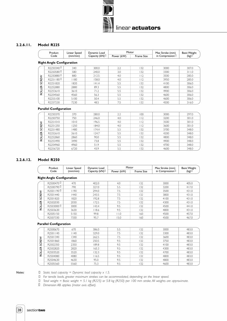
28
linear actuators
sectiontwo
2.2.6.11. Model R225
2.2.6.12. Model R250
Notes: ➀ Static load capacity = Dynamic load capacity x 1.5.➁ For tensile loads, greater maximum strokes can be accommodated, depending on the linear speed.➂ Total weight = Basic weight + 5.1 kg (R225) or 5.8 kg (R250) per 100 mm stroke. All weights are approximate.
Dimension AB applies (motor axis offset).
R2250340R2250580R2250880R2251180R2251820R2252880R2253610R2254560R2255100R2257230
3405808801180182028803610456051007230
300.0240.0212.5158.0141.489.371.256.350.448.5
2.23.04.04.05.55.55.55.55.57.5
132132112112132132132132132132
3000330035003950410048004900460046004500
307.0311.0285.0285.0306.0306.0306.0306.0306.0316.0
ProductCode
Linear Speed(mm/min)
Dynamic LoadCapacity (kN)
Max Stroke (mm)in Compression
Basic Weight(kg)
MotorPower (kW) Frame Size
ROLL
ER S
CR
EW
➀ ➁ ➂
Right Angle Configuration
R2250370R2250750R2251010R2251250R2251480R2252610R2252860R2253490R2254960R2256720
37075010101250148026102860349049606720
280.0246.0196.5184.0174.4124.790.073.851.943.9
2.24.04.04.05.55.55.55.55.55.5
100112112112132132132132132132
3000320035003600370042004800490047004600
297.0301.0301.0301.0348.0348.0348.0348.0348.0348.0
ROLL
ER S
CR
EW
Parallel Configuration
➃
➃
➃
➃
R2500470R2500790R2501190R2501440R2501820R2502030R2503000R2503630R2505150R2507330
47079011901440182020303000363051507330
402.0327.0294.0243.5192.8172.5143.4118.699.895.7
4.05.57.57.57.57.59.59.511.015.0
132132132132132132132132160160
3000320035003800410043004500480045004500
405.0417.0431.0431.0431.0431.0441.0431.0457.0467.0
ProductCode
Linear Speed(mm/min)
Dynamic LoadCapacity (kN)
Max Stroke (mm)in Compression
Basic Weight(kg)
MotorPower (kW) Frame Size
ROLL
ER S
CR
EW
➀ ➁ ➂
Right Angle Configuration
R2500670R2501140R2501340R2501860R2502350R2502820R2503520R2504080R2504630R2505560
670114013401860235028203520408046305560
386.0329.0262.5250.5189.8165.3132.3116.595.075.3
5.57.57.59.59.59.59.59.59.59.5
132132132132132132132132132132
3000330036003750410043004700480048004600
483.0483.0483.0483.0483.0483.0483.0483.0483.0483.0
ROLL
ER S
CR
EW
Parallel Configuration
➃
➃
➃
➃
➃

29
linear actuators
sectiontwo
2.2.7. Rolaram Linear Actuator Dimensions
2.2.7.1. Rolaram - Parallel Motor Configuration - Trunnion Mount
D
J Motor IBrake K
Motor ØH
ØB
ØA
EØ
A
AF
C
GuidedOption
L
N
E
G F M
2.2.7.1.1. Rolaram Actuators with Roller Screw
2.2.7.1.2. Rolaram Actuators with Ball Screw
R050 R075 R100 R125 R150 R175 R250R225Size Frame
80Frame
71Frame
63Frame
63AØBØCDEFG
HØIJKLMNAEAF
10240208
158
122
118
26777110125
360
272
145248
68125
340
264
130227
60113
Frame80
Frame71
12050248
190
147
143
32490142110
409
337
162266
67137
385
337
145242
68125
Frame90
Frame90
Frame80
14570305
226
178
160
387107160145
1759032046322638517818130316075147387107185180
463
385
181303
75147
426
385
162266
67137
Frame112
Frame100
255140465
306
251
213
527146270180
581
522
228368
95171
558
522
203345
90158
Frame132
Frame132
275150560
350
281
307
581172285190
750
586
266443
122196
660
530
266447
122196
Frame100
Frame90
195110385
255
206
200
438123206165
545
454
203345
90158
510
454
181310
75147
Frame112
3568
454
228368
95171
Ava
ilabl
e on
req
uest
Ava
ilabl
e on
req
uest
B050 B075 B100 B125Size Frame
80Frame
71Frame
63Frame
63AØBØCDEFG
HØIJKLMNAEAF
10275208
158
122
118
26777110125
360
272
145248
68125
340
264
130227
60113
Frame80
Frame71
12092248
190
147
143
32490142110
409
337
162266
67137
385
337
145242
68125
Frame90
Frame80
145106305
226
178
160
387107160145
463
385
181303
75147
426
385
162266
67137
Ava
ilabl
e on
req
uest
Ava
ilabl
e on
req
uest
Notes 1. All dimensions are in millimeteres (mm)unless otherwise stated.
2. “Frame” refers to IEC motor frame size.3. Dimensions subject to change without
notice.

30
linear actuators
sectiontwo
2.2.7.2. Rolaram® - Parallel Motor Configuration - Rear Clevis MountNew Rolaram with rear clevis mounting enables the actuator to be configured for double clevis arrangements.
Details below are for the B050 Rolaram Actuator only. For all other sizes contact Power Jacks.
2.2.7.2.1. B050 - Rolaram®
Standard Clevis, Top Plate and Threaded Ends are available on request.
Notes 1. All dimensions are in millimetres (mm) unless otherwise stated.2. “Frame” refers to IEC motor frame size.3. Dimensions subject to change without notice.
ØD
ØB
Travel A
ØBA
L
ØM
ØE
P QNR
C
G
S
F
S
J
KH
NEW
Frame
63
71
80
A
432 + Stroke
432 + Stroke
432 + Stroke
B
20 H8
20 H8
20 H8
C
120
120
120
D
50
50
50
E
80
80
80
F
176
176
176
G
88
88
88
H
282
282
282
Frame
63
71
80
N
160 + Stroke
160 + Stroke
160 + Stroke
J
85
85
85
K
197
197
197
L
471
499
543
M
122
137
158
P
112
112
112
Q
110
110
110
S
25
25
25
R
50
50
50

31
linear actuators
sectiontwo
2.2.7.3. Rolaram® - Right Angled Motor Configuration - Trunnion Mount
2.2.7.3.1. Roller Screw and Ball Screw
Motor V
ØW
ØS
PY
X O AF
ØB ØA ØAE
U(Brake)
Guided Option
AB
R
Q
R/B 050 R/B 075 R/B 100 R/B 125 R/B 150Size Frame 80Frame 71
OPQR
SØTUV
WØXY
ABAEAF
157.5
110158
62
10110125
155 max
14520768186160
220.5 max
209 max
16223267223200
274.5 max
Frame 90Frame 80 Frame 100Frame 90 Frame 100Frame 90 Frame 112
190
140193
60
12142110
233 max
16223267223200
316 max
245 max
18127575226200
328 max
210
140193
72
12160145
243max
18127575226200
326 max
255 max
20330590261250
338 max
236.5
170235
85
18185180
292 max
22832595273250
390 max
295 max
20330590261250
393 max
285 max
18127575226200
383 max
Ava
ilabl
e on
req
uest
Ava
ilabl
e on
req
uest
R/B 175 R/B 225 R/B 250Size
OPQR
SØTUV
WØXY
ABAEAF
Frame 112Frame 100 Frame 112Frame 132 Frame 132Frame 132 Frame 160
300
210291
107
22206165
270 max
20330590261250
391 max
343 max
22832595273250
464 max
365
240338
128
26270180
363 max
266395122323300
484 max
332 max
22832595273250
468 max
370
280406
151
32285190
383max
326521130380350
546 max
383 max
266395122323300
546 max
427 max
266395122323300
563 max
T(Motor)
Notes 1. All dimensions are in millimeteres (mm) unless otherwise stated.2. “Frame” refers to IEC motor frame size.3. Dimensions subject to change without notice.

32
linear actuators
sectiontwo
2.2.7.4. End Fittings and Mountings
YY XX
FF
GG
BB
ØZ
AA
WWAC
EE
VVYY
ØCCDD
MM
ZZ + Stroke AD
NN
SS
PPQQ AG
KK
HH
OO
TT + Stroke
RR UUØII YY JJ
LL + Stroke KK
Trunnion
Top Plate Clevis End Screwed End
Trunnion Feet/End Cap Foot
YY
075 100 125 150 175 225 250Size202325
105 (145)14
4 x Ø13.5 x 80PCD (115)M24 x 3
352113532115300851425110060120
6 x Ø13.528116020284050301203970
283230
130 (175)18
4 x Ø18 x 100PCD (140)M36 x 4
4029045451603051002035014080145
6 x Ø223052052337454133528
40.590
353835
170 (210)22
4 x Ø22 x 130PCD (165)M36 x 4
5032560501753631102538915490180
6 x Ø2640725027455724442357.585
42474022026
4 x Ø26 x 170PCD
M48 x 560324706019049512035412238150210
6 x Ø33505300325467505504535110
55625027033
4 x Ø33 x 205PCD
M68 x 675355958019575015040453308210260
6 x Ø39767370407285588225541135
70787030033
6 x Ø33 x 235PCD
M80 x 6905301109026085018045640350240280
6 x Ø459034105290102329687012155
80908033039
6 x Ø39 x 260PCD
M80 x 612561012510531075019550742400268350
6 x Ø5279050060105140608658035180
ZØ (H7)AABB
CCØDDEE
FFGGHH
IIØ (F7)JJ
KKLL
MMNNOOPP
QQRRSSTTUUVV
WWXXYYZZACADAG
Notes 1. Dimensions in brackets refer to Ball Screw Models.

33
linear actuators
sectiontwo
2.2.8. Rolaram® Accessories and Options
2.2.8.1. Limit Switches
2.2.8.1.1. Standard Rolaram® Actuator Limit Switch• Inductive proximity switches
• Cylindrical design M18 x 1
• Standard housing made from brass or stainless steel.
• DC-voltage
• Sizes: A = 60 mm, B = 51.5 mm
2.2.8.1.2. Rolaram® Limit Switch Technical Data
2.2.8.1.3. Optional Rolaram® Actuator Limit SwitchOther limit switches can be supplied to suit most applications e.g.
• Different sizes, shape, design and enclosure electro-mechanical limit switches.
• Inductive proximity sensor (refer section 8.2.1.).
• Hazardous Area rated electro-mechanical limit switch.
• High or low temperature rated limit switches or sensors.
For all of these options consult Power Jacks for details.
2.2.8.2 Encoders for Rolaram® ActuatorsEncoders for Rolaram linear actuators can be provided fitted to the rear of the electric motor (beneath the cowling). The encoderspecification is in general similar to that shown in section 8.3. For further details please consult Power Jacks.
2.2.8.3 Optional Materials for Rolaram® Actuator ConstructionAs with all other Power Jacks products these actuators can be manufactured with alternative materials to meet the most demandingapplication. Consult Power Jacks for advice.
a
b
Parameter
Type
Housing Material
Nominal Sensing Distance, Sn
Weight (kg)
Connecting Cable
Degree of Protection
Sensing Distance, Sr
Repeat Accuracy, R
Diffential Travel, H
Operating Temperature
Output State Indicator
Voltage, Uo
Operating Voltage, Ub (including residual ripple)
Switching Power, I
Voltage Drop, Ud (output controlled)
Residual Current, Ir (output locked)
Idle Current, Ia
Maximum Switching Frequency, f
Delay Times
Data
Four-wire PNP/NPN/NO/NC programmable
Brass housing
5mm
0.120
4 core x 0.34 mm 2, 2m long (other lengths available on request)
IP 68
0 → 4mm
3% of Sr
1 → 15% of Sr
-25 → +80o C
LED
12 → 24 VDC
10 → 38 VDC
0 → 200 mA, including overload and short circuit connection
2.6 V
-
10 mA
2000 Hz
Stand-by delay tv = 5ms, Switch-on time ton = 1.15 ms, Switch-off time toff = 0.35 ms

34
linear actuators
sectiontwo
2.2.9. Special Rolaram® Designs and Applications
Actuator R150 model, roller screw version, in-line drive.
Application Driving reciprocating, double acting paint pumps in the first all-electric paint mix facilityin Europe.
Linear The dynamic load is 17.9 kN in both directions, at a linear speed of 3 metres/minuteActuation and a continuous duty cycle of 24 hours/day, 365 days/year. Each pump delivers 40 litresRequirements of paint/minute at 12 bar, 12 cycles/minute. The paint shop output is 30 cars/hour
(Phase 1) and 60 cars/hour (Phase 2).
Solution Each pump is driven by a special R150 Rolaram actuator and a total of 31 actuator andpump systems are installed.
The actuator's features are:
• In-line configuration, minimizingthe installation footprint.
• Completely sealed unit, ensuringno contamination of thepumped medium.
• Intrinsically safe, eliminatingexplosion risk.
• Fitted with a keyed screwmechanism.
An electro mechanical solution waspreferred to pneumatics/hydraulics due to significantly reducedrunning costs, high life and reliability, high efficiency, low maintenance,low paint degradation and quiet operation.
Actuator B100 model, ball screw version, parallel drive.
Application Full body, multi purpose X ray examination table.
Linear The dynamic load is 65 kN and high positional accuracy is required toActuation achieve a defined axial play of the ram. Due to the clinical environment,Requirements the ability to tilt and elevate at the same time is unique and no other
table on the marketplace is available with this feature. Operating in amedical environment, a major requirement of the actuators is low noiseand the units cannot exceed 60 dB.
Solution Two B100 ball screw Rolaram actuators, both paralleldrive configurations, are fitted on each X ray table andthey are synchronized for horizontal and verticalpositioning through a complex servo control system.The actuators are tested to withstand 8 times themaximum load, without catastrophic failure. Due tospace constraints, they are of a compact design andconform to strict aesthetic criteria.

35
linear actuators
sectiontwo
Actuator Spring return actuator, ball screw version, in-line drive.
Application Failsafe operation of ventilation dampers.
Linear The actuator opens and closes the damper and maintains a 3 kNActuation load to ensure that the damper is sealed. The damper must openRequirements and close in 2 seconds and operate at 250°C for 1 hour. In the
event of power failure, the actuator must failsafe in the closedposition.
Solution One off ball screw actuator is fitted onto each damper. The actuatorcontains a pre-loaded spring and is fitted with a high temperaturebrake motor. The internal spring and drive configuration will allowthe ram to retract automatically in the event of power failure. Threeadjustable limit switch positions are provided and the stroke can beset within the allowable 120 mm, by adjusting these switches. Allcomponents are selected for the appropriate approved temperaturerequirement. The actuator has a fire test certificate for operation at250°C for 1 hour.
Actuator R175 model, roller screw version, right angle drive.
Application Positioning a weir gate for water level adjustment.
Linear The actuator moves a dynamic load of 150 kN (static load of 330 kN),Actuation at a linear speed of 240 mm/minute, has a stroke of 2700 mm and aRequirements life requirement of 40 years.
Solution One actuator is fitted on each weir gate and has several specialfeatures
• Universal joint at the ram end to compensate for misalignmentand to resist the load torque.
• Geared motor drive with hand wind facility.
• Positional indication and end of travel limit switches.
• Non contaminating grease.
This application is in a remote location and an electro mechanicalsolution was preferred over hydraulics due to low powerrequirements, no expensive hydraulic power pack, no hydraulic fluidleakage i.e. no water contamination and minimal maintenance.

36
linear actuators
sectiontwo
2.2.10. Rolaram® Actuator Installation and Maintenance Tips
2.2.10.1. MountingThere are two possible ways of mounting the Rolaram actuator at the gearbox end. By means of bearing journals for trunnion mountingor clevis mount.
2.2.10.1.1. Rear Clevis• Mount the actuator by attaching the desired bracket and pin to the clevis end.
• Verify that the ram attachment is aligned throughout the actuator stroke before connecting the ram. The ramattachment will either be pinned or bolted in place depending on chosen model.
2.2.10.1.2. Trunnion Mount• Mount the actuator by attaching the desired bearings (or mounting feet) to the trunnion pins.
• Verify that the ram attachment is aligned throughout the actuator stroke before connecting the ram. The ramattachment will either be pinned or bolted in place depending on chosen model.
Important Note: Always ensure that clevis holes align correctly and that they allow for the correct angle of pivoting forthe application before operating the actuator.
Important Note: Side loads on the actuator ram should be avoided by ensuring that the load is guided. The load guidemechanism should resist the torque developed at the ram by the screw mechanism. A guided ram canbe supplied on request, which utilises a keyway in the inner ram, eliminates the need for torsionalrestraint and therefore allows flexibility in the choice of end fitting.
The desired mounting orientation will be determined when placing the order ; this orientation must be maintained atinstallation.
2.2.10.2. Lubrication of Rolaram® Actuator
2.2.10.2.1. Lubrication of the Lifting NutLubricate the SPIRACON-nut or ball-nut assembly and the bearing housing by the corresponding lubricating points.
With the SPIRACON-nut or ball-nut assembly in the correct position, the lubrication point is accessible through the access plug on theouter tube.
Lubrication interval: Every 6 months
Standard grease type: Lifting-nut assembly: ROCOL MTS 1000
Bearing housing: Mobilgrease HP 222
Important Note: The SPIRACON-nut assembly may only be readjusted by Power Jacks.
2.2.10.2.2. Lubrication of the GearboxInspection interval: The oil level of the gear-box must be checked every 3 months and, if necessary, oil must be
topped up.
Oil change interval: After two years or 10,000 operating hours.
Standard oil: Mineral oil Shell OMALA 220.

POWER JACKSGroupmanufacturers of precision screw jacks, actuators and gearboxes
Planetary Roller Screw
High dynamic load capacity up to 1200 kN
High efficiency
High positional accuracy
Long life
Low maintenance
Low noise
3. spiracon™ roller screws

1
screw drives
sectionthree
Contents
3. Screw Drives
3.1. Spiracon™ Roller Screw 23.1.1. Spiracon™ Roller Screw Overview 2
3.1.2. Working Applications for Spiracon™ Roller Screws 4
3.1.3. Spiracon™ Roller Screw Product Code 5
3.1.4. Spiracon™ Roller Screw Range 6
3.1.5. How to Select a Spiracon™ Roller Screw 7
3.1.6. Spiracon™ Roller Screw Technical Data and Dimension 10
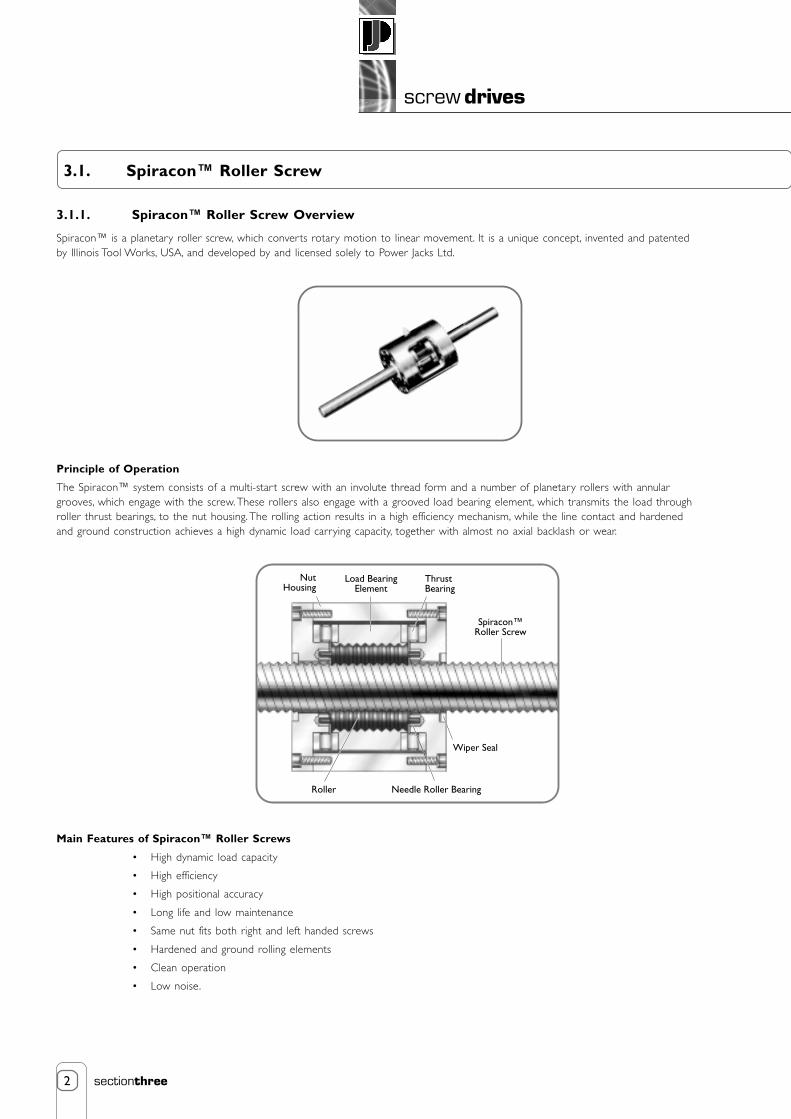
2
screw drives
sectionthree
3.1. Spiracon™ Roller Screw
3.1.1. Spiracon™ Roller Screw Overview
Spiracon™ is a planetary roller screw, which converts rotary motion to linear movement. It is a unique concept, invented and patentedby Illinois Tool Works, USA, and developed by and licensed solely to Power Jacks Ltd.
ThrustBearing
Wiper Seal
Load BearingElement
NutHousing
Needle Roller BearingRoller
Spiracon™Roller Screw
Main Features of Spiracon™ Roller Screws
• High dynamic load capacity
• High efficiency
• High positional accuracy
• Long life and low maintenance
• Same nut fits both right and left handed screws
• Hardened and ground rolling elements
• Clean operation
• Low noise.
Principle of Operation
The Spiracon™ system consists of a multi-star t screw with an involute thread form and a number of planetary rollers with annulargrooves, which engage with the screw. These rollers also engage with a grooved load bearing element, which transmits the load throughroller thrust bearings, to the nut housing. The rolling action results in a high efficiency mechanism, while the line contact and hardenedand ground construction achieves a high dynamic load carrying capacity, together with almost no axial backlash or wear.

3
screw drives
sectionthree
Advantage over Ball Screws
• Higher dynamic load capacity
• Larger diameters and higher leads
• Higher positional accuracy
• Longer life
• Higher stiffness
1200
1100
1000
900
800
700
600
500
400
300
200
100
0100 20 30 40 50 60 70 80 90 100 110 120
Spira
con™
Rol
ler S
crew
sBall Screw
Screw Diameter (mm)
Dyn
amic
Loa
d (k
N)
• Higher speed and acceleration
• Low temperature operation
• Lower noise
• Nut easily removed with rollers retained
• Higher safety.
Applications for Spiracon™ Roller Screws
Spiracon™ roller screws are well proven throughout the world in a wide variety of industries including:
• Nuclear
• Aerospace
• Metal processing
• Medical
• Automotive
• Food Processing
• Paper
• Offshore and marine
• Communications
• Defence
Typical applications include:
• Robotics
• Laser tracking
• Indexing/adjusting
• Simulators
• Seismic testing
• Shield door adjustment
• Machine Tools
• Antenna dish adjustment
• Clamping mechanisms
• Medical scanners
• Continuous casting . . .

4
screw drives
sectionthree
3.1.2. Applications for Spiracon™ Roller ScrewsApplication Anti-sway mechanism on ship-to-shore container cranes in
Hong Kong.
Linear All 4 screws and nuts required to be synchronised. HighActuation loads and an aggressive marine environment were alsoRequirements factors.
Solution Four model 65 mm Spiracon™ roller screws (2 left handand 2 right hand) with associated bevel gearboxes,couplings and shafting, per crane.
Application Flying shear for cutting to length pre-formedsteel sheets.
Linear The shear required to be operatedActuation continuously and accurate repeatability ofRequirements positioning was important. Long life and low
maintenance were necessary.
Solution Model 55 mm Spiracon™ roller screwoperating on a continuous reversal basis.
Application Clamping machine for reclamation of steel rolls.
Linear High dynamic load requirement, reliability of operationActuation and a demanding operating environment.Requirements
Solution Model 75 mm Spiracon™ roller screw operating avertical clamp, to hold steel rolls in position.
Application Road bridge inspection and maintenanceplatforms.
Linear Safety was the overriding requirement, asActuation human cargo was involved. The units wouldRequirements be subjected to high load requirements and
hostile weather conditions.
Solution Two 15 tonne platforms, raised and loweredby model 75 mm Spiracon™ roller screws,fitted with disk brakes and mechanical stopsas safety features.

5
screw drives
sectionthree
3.1.3. Spiracon™ Roller Screw Product CodeThe product code is of the following form:
(1) ProductSPT - Spiracon™ Screw and Nut.SPS - Spiracon™ Screw only.SPM - Spiracon™ Nut only.
(2) ModelA 3 figure code taken from the Technical Chart (Refer 3.1.6.).
(3) LeadA 2 figure code taken from the Technical Chart (Refer 3.1.6.).
(4) PitchA 1 figure code taken from the Technical Chart (Refer 3.1.6.).
(5) Direction of ThreadRH - Right HandLH - Left Hand.
(6) Overall Screw LengthA 4 figure code to represent the overall screw length in mm.
(7) Screw Threaded LengthA 4 figure code to represent the threaded length of the screw in mm ie stroke (travel) + B (nut length) + overtravel at each end.
(8) Number of Siracon™ NutsA 1 figure code to represent the number of nuts required.
(9) Nut Mounting HolesO - Standard Mounting HolesS - To Customer Drawing
S P T 0 6 5 6 R H 1 5 4 0 1 4 5 0 1 0
(1) Spiracon™ Screw and Nut(2) Model 65(3) 36 mm Lead(4) 6 mm Pitch(5) Right Hand Thread
(6) 1540 mm Overall Screw Length(7) 1450 mm Screw Threaded Length(8) 1 Spiracon™ Nut(9) Standard Nut Mounting Holes
Example Part Number
Notes: 1. In all cases, the customer should supply a detailed drawing, indicating the screw end matching details.2. The above part number defines a standard catalogue unit. Where a standard unit does not meet the
customer's requirement, Power Jacks will be pleased to design a special unit.3. All goods are sold subject to our Standard Conditions of Sale, a copy of which is available upon request.
(1) (4)(2)
- -
(6) (8)
-
(9)
--
(5)
-3 6
(3)
-
(7)
-
(1) (4)(2)
- -
(6) (8)
-
(9)
-
(5)
-
(3)
-
(7)
-
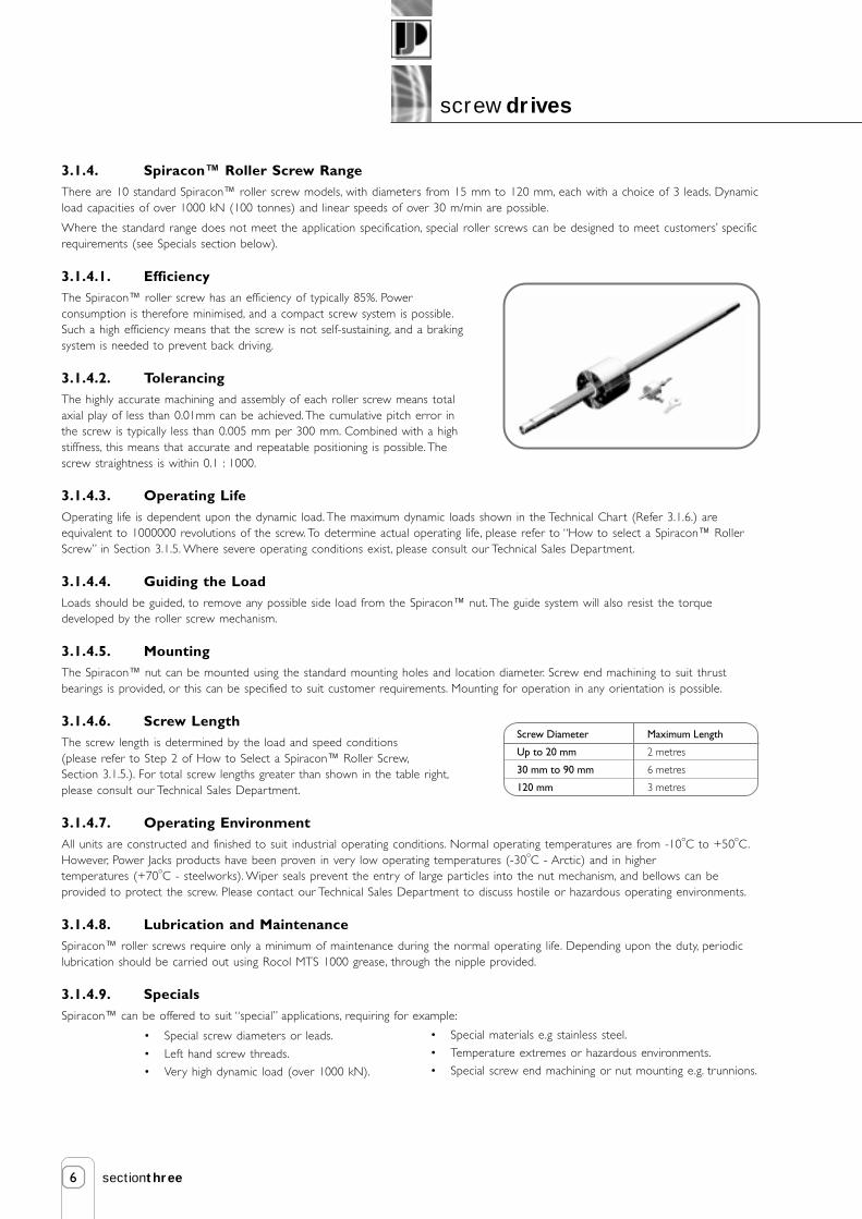
6
screw drives
sectionthree
3.1.4. Spiracon™ Roller Screw RangeThere are 10 standard Spiracon™ roller screw models, with diameters from 15 mm to 120 mm, each with a choice of 3 leads. Dynamicload capacities of over 1000 kN (100 tonnes) and linear speeds of over 30 m/min are possible.
Where the standard range does not meet the application specification, special roller screws can be designed to meet customers’ specificrequirements (see Specials section below).
3.1.4.1. EfficiencyThe Spiracon™ roller screw has an efficiency of typically 85%. Powerconsumption is therefore minimised, and a compact screw system is possible.Such a high efficiency means that the screw is not self-sustaining, and a brakingsystem is needed to prevent back driving.
3.1.4.2. TolerancingThe highly accurate machining and assembly of each roller screw means totalaxial play of less than 0.01mm can be achieved. The cumulative pitch error inthe screw is typically less than 0.005 mm per 300 mm. Combined with a highstiffness, this means that accurate and repeatable positioning is possible. Thescrew straightness is within 0.1 : 1000.
3.1.4.3. Operating LifeOperating life is dependent upon the dynamic load. The maximum dynamic loads shown in the Technical Chart (Refer 3.1.6.) areequivalent to 1000000 revolutions of the screw. To determine actual operating life, please refer to “How to select a Spiracon™ RollerScrew” in Section 3.1.5. Where severe operating conditions exist, please consult our Technical Sales Department.
3.1.4.4. Guiding the LoadLoads should be guided, to remove any possible side load from the Spiracon™ nut. The guide system will also resist the torquedeveloped by the roller screw mechanism.
3.1.4.5. MountingThe Spiracon™ nut can be mounted using the standard mounting holes and location diameter. Screw end machining to suit thrustbearings is provided, or this can be specified to suit customer requirements. Mounting for operation in any orientation is possible.
3.1.4.6. Screw LengthThe screw length is determined by the load and speed conditions(please refer to Step 2 of How to Select a Spiracon™ Roller Screw,Section 3.1.5.). For total screw lengths greater than shown in the table right,please consult our Technical Sales Department.
3.1.4.7. Operating EnvironmentAll units are constructed and finished to suit industrial operating conditions. Normal operating temperatures are from -10oC to +50oC.However, Power Jacks products have been proven in very low operating temperatures (-30
oC - Arctic) and in higher
temperatures (+70oC - steelworks). Wiper seals prevent the entry of large particles into the nut mechanism, and bellows can beprovided to protect the screw. Please contact our Technical Sales Department to discuss hostile or hazardous operating environments.
3.1.4.8. Lubrication and MaintenanceSpiracon™ roller screws require only a minimum of maintenance during the normal operating life. Depending upon the duty, periodiclubrication should be carried out using Rocol MTS 1000 grease, through the nipple provided.
3.1.4.9. SpecialsSpiracon™ can be offered to suit “special” applications, requiring for example:
• Special screw diameters or leads.
• Left hand screw threads.
• Very high dynamic load (over 1000 kN).
Screw Diameter
Up to 20 mm
30 mm to 90 mm
120 mm
Maximum Length
2 metres
6 metres
3 metres
• Special materials e.g stainless steel.
• Temperature extremes or hazardous environments.
• Special screw end machining or nut mounting e.g. trunnions.

7
screw drives
sectionthree
3.1.5. How to Select a Spiracon™ Roller ScrewThere are 3 simple steps as follows :
Step 1 Load, Speed and LifeFrom the Technical Chart in Section 3.1.6., make an initial selection of a Spiracon model to suit the required maximum dynamic andstatic loads.
Choose a screw lead and calculate the rotational speed to suit the required linear speed:
Rotational speed = Linear speed (mm/minute) Screw lead (mm)
Check that the rotational speed is below the maximum speed shown in the Technical Chart for the model selected.
Calculate the total number of revolutions of the screw for the operating life required:
Required no. of screw revs. = Life (hours) x Rotational speed (rpm) x 60
Check the operating life for the selected Spiracon model:
C = Dynamic capacity (kN) from Technical ChartF = Application dynamic load (kN) (or Fm, mean load as below)
Actual no. of screw revs. = C 3.33 x 10 6
F
Actual life in hours = No. of screw revs. Rotational speed x 60
If required, reiterate the calculation to achieve the required life.
Where the dynamic load varies, the mean load (Fm) can be approximated as follows:
Fm = 3 (F13 x U1) + (F23 x U2) + ... U
F1, F2 = constant loads during U1, U2 revolutions
U = total number of revolutions
Where the dynamic load varies between a minimum (Fmin) and maximum (Fmax) the mean load is :
Fm = Fmin + 2 x Fmax 3
Step 2 Critical Speed, Buckling and Deflection
Establish length (L) based on the required stroke and bearing support conditions. For length (L), check that the rotational speed isbelow the critical speed limit, given by the formula:
Critical speed limit (rpm) = 107 x f1 x J L2
Where f1, f2 and f3 are defined by the bearing support conditions shown in the diagram overleaf, and J is the root diameter of theSpiracon™ thread given in the Technical Chart in section 3.1.6.
Where the screw is under a compression load, check that the chosen screw diameter and length (L) are within the load limit forbuckling, given by the formula:
Load limit (N) = 104 x f2 x J4
L2
For long horizontal screws, check the deflection of the screw under its own weight:Deflection (mm) = 6 x 10⁻⁹ x L4
f3 x J2
( )•••
Model
15
20
Lead
6
12
6
12
18
Pitch
1
2
1
2
3
DynamicC
(kN)
45
35
58
58
50
StaticCo
(kN)
68
52
87
87
74
AØ
92
92
103
103
103
NUTB
90
90
110
110
110
CØ
H6
34
34
45
45
45
D
40
40
40
40
40
Full table in 3.1.6.

8
screw drives
sectionthree
Bearing Support Conditions
Step 3 Torque and PowerCalculate the torque required to drive the screw:
Dynamic load (N) x Lead (mm) Torque (Nm) x Rotational speed (rpm) 2000 x π x Efficiency (0.85) 9550
Note: Where there is a high acceleration or inertia, please consult out Technical Sales Department.
1
2
3
L
L
L
f1 f2 f3
21 12.5 384
15 6.5 185
9.5 3 77
3.4 0.8 8
Torque (Nm) = Power (kW) =
4
L

9
screw drives
sectionthree
3.1.5. How to Select a Spiracon™ Roller ScrewExample
Select a standard right hand Spiracon screw and nut for the following:
Dynamic load = 220 kN (in compression)
Linear speed = 900 mm/minute
Required life = 2000 hours
Required stroke = 1200 mm
Overall screw length = 1850 mm
Screw mounting = Vertical
Bearing support condition = 2
Step 1
From the char t in section 3.1.6., make initial selection of: Model 65 x 36 lead
Select a lead of 36mm to give a rotational speed of: 900= 25 rpm (OK<1700 rpm)
36
Calculate the number of revolutions of the screw to give the required life: Required no. of screw revs. = 2000 x 25 x 60 = 3 x 10⁶
Check the operating life for selected Spiracon model: 3103.33 x 106
220
= 3.14 x 10⁶ (OK>3 x 10⁶)
3.14 x 10⁶
25 x 60
(OK>2000 hours)
Step 2
Stroke = 1200 mm
Length (L) = 1600 mm(refer bearing support condition)
Check the critical speed limit: Speed limit (rpm) 107 x 10 x 63.7 16002
= 2488 rpm (OK>25 rpm)
Check for buckling of the screw: Load limit (N) 104 x 6.5 x 63.74
16002
= 418 kN (OK>220 kN)
Step 3
The torque and power are: Torque (Nm) 220000 x 362000 x π x 0.85
Power (kW) 1483 x 25 9550
The complete product code is SPT-065-36-6-RH-1850-1500-1-0 (refer 3.1.3. for full breakdown of this code)
•••
•••
Actual no. of screw revs. =
= 2093 hours=Actual life in hours
=
=
=
= = 3.88 kW
= 1483 Nm

10
screw drives
sectionthree
3.1.6. Spiracon™ Roller Screw Technical Data and Dimensions
Note: * = Customer to define at time of ordering.ØJ = Root diameter of Roller screw
Technical Dimensional Chart(all dimensions are in millimetres)
B
D
G
H ØA
F
ØE
ØCSee Note*Threaded LengthSee Note *
Overall Length
Lubrication
Model
15
20
30
40
45
55
65
75
90
120
Lead
6126121861824122432122448122448243654243654243654244054
Pitch
12123133234246246466466466456
DynamicC
(kN)
45355858501009010512012811519017012029027027534031031038034034053052061595012001200
StaticCo
(kN)
685287877415012015018019217228525518043540541050046545557051051079578092042518001800
AØNUT SCREW
9292103103103125125125135135135170170170205205205240240240275275275315315315420420420
CØ
H6
3434454545505050656565757575858585959595105105105120120120150150150
EPCD
5555585858707070838383105105105128128128150150150165165165200200200250250250
FDia x No
M8 X 6M8 X 6M8 X 8M8 X 8M8 X 8M10 X 8M10 X 8M10 X 8M12 X 8M12 X 8M12 X 8M16 X 8M16 X 8M16 X 8M20 X 8M20 X 8M20 X 8M20 X 8M20 X 8M20 X 8M20 X 8M20 X 8M20 X 8M24 X 10M24 X 10M24 X 10M24 X 12M24 X 12M24 X 12
HØ
1717212121
30.830.830.8393939
46.646.646.656.156.156.168.868.868.875.275.275.2909090120120120
WEIGHTSNut
(kg)
3.53.55.55.55.59.39.39.311.011.011.023.223.223.244.044.044.066.5066.5066.5087.487.487.4137137137310310310
JØmin
15.315.318.418.418.428.228.228.235.535.535.541.341.341.350.950.950.963.763.763.770.170.170.1858585115115115
B
9090110110110130130130135135135180180180229229229250250250260260260310310310400400400
D
44444444444555555555666888888
G
1212121212151515181818242424303030303030303030353535505050
MaxSpeed(rpm)
55005500490049004900430043004300330033003300260026002600210021002100170017001700160016001600120012001200100010001000
Screwper 100 mm
(kg)
0.180.180.270.270.270.550.550.550.920.920.921.31.31.31.921.921.922.832.832.833.453.453.454.964.964.968.828.828.82
Dimensions subject to change without notice.

4. bevel gearboxes (neeter drive)
Compact ‘Monobloc’ Design2-way, 3-way and 4-waySolid Shaft and Hollow ShaftManual Disengage / Reversing Types1:1, 2:1 and 3:1 gear ratiosPower Ratings: 0.1 ➔ 7.35 kWTorque Ratings: 1.5 Nm ➔ 40 Nm
Section 4.1. - Bevel Gearboxes Range P
Ultra Compact Design2-way, 3-way and 4-waySolid Shaft and Hollow ShaftMotor Adaptors1:1, 2:1, 3.1 and 4:1 gear ratiosPower Ratings: 0.1 ➔ 226 kWTorque Ratings: 15 Nm ➔ 3000Nm
Section 4.2. - Bevel Gearboxes Range N
Cubic shape with universal mounting on all sides2-way, 3-way and 4-waySolid Shaft and Hollow ShaftMotor Adaptors1:1, 2:1, 3:1, 4:1, 5:1 and 6:1 gear ratiosTorque Ratings: 10 Nm ➔ 9000 Nm
Section 4.3. - Bevel Gearboxes Range BA
More than 100% more performance for construction sizesCompact cubic design mounting holes on all sides2-way, 3-way and 4-waySolid Shaft and Hollow ShaftMotor Adaptors1:1, 2:1, 3:1, 4:1 and 5:1 gear ratiosTorque Ratings: 25 Nm ➔ 5200 Nm
Section 4.4. - Bevel Gearboxes RangePower Gear
NEETER DRIVES P I R A L B E V E L G E A R B O X E S

1
bevel gearboxes
sectionfour
Contents
4. Bevel Gearboxes - Neeter Drive
4.1. Bevel Gearboxes - Neeter Drive - Range - P 24.1.1. Netter Drive - Range - P - Design Overview 2
4.1.2. Series P - 2000 3
4.1.3. Series P - 2000 - Manual Disengage/Reversing 4
4.1.4. Series P - 4000 4
NEETER DRIVES P I R A L B E V E L G E A R B O X E S

2
bevel gearboxes
sectionfour
4.1. Bevel Gearboxes - Neeter Drive - Range - P
4.1.1. Neeter Drive - Range - P - Design Overview
4.1.1.1. General Design Feature HousingA compact “monobloc” design provides a visually attractive, quality finished, casing, produced from die-casting, in lightweight, aluminiumalloy. Several alternative fixing options are provided each via 4 fixing holes, as well as, through 4 holes in integrally cast, small base-mounting bosses, on widely-spaced centres - for more stable mounting, to top or bottom thereby offering universal and exceptionallyfirm attachment facilities.
4.1.1.2. Bevel GearsThe GLEASON spiral bevel gears, of case-hardened alloy steel, provide an advancing, simultaneous mesh across several adjacent teeth,thereby ensuring smooth, evenly distributed, high load transmission, which is enhanced by, bi-directional, “running-in”, in pairs.
4.1.1.3. ShaftsShafts are of case-hardened and ground alloy-steel. Exceptions are: both, the smallest casting sizes, types 2000 & 2002 and types 2012 &2028, where shafts are all of hardened and tempered, low alloy-steel. Bearings All shafts are carried by generously sized, high quality,deep groove, ball bearings of established make.
4.1.1.4. Design Speed and LifeOptimum performance, at continuous full rated power transmission, is based on an input-shaft design-speed of 1400 RPM. This providesan average, trouble-free, operating design-life of 10000 hours. However, where “ratio geared” units are used as speed “increasers”,optimum performance, “input” design-speed is reduced to 500 RPM for the 1:3 ratios and, to 750 RPM for the 1:2 ratios. For all thetypes 4-way and 3-way independent shaft with a gear ratio different of 1:1, the input shaft is the shaft A (quickly), the shaft C (quickly)is the out shaft, the shafts B and D are slow.
4.1.1.5. Operating TemperatureDue to the compact “monobloc” design, operating case-temperature should be kept within the permissible limit of -18 °C to +80 °C(0°F to 170°F), to ensure trouble-free running.
4.1.1.6. Operating NoiseClose tolerance gear cutting and high accuracy assembly ensures extremely low operating noise levels, even at high running speeds.
4.1.1.7. Alignment AccuracyStandard unit, final gear train assembly, angular clearances are held to within 15' - 30' of arc.
4.1.1.8. LubricationAll units are supplied fully charged with oil. The 2000 series is lubricated with synthetic oil. The lubrication is a life one, they do not needreplenishments or changes for the lifetime of the gear.
The above details are for series 2000 gearboxes. For 4000 gearbox details please consult Power Jacks.
For full catalogue with dimensions please consult Power Jacks.

3
bevel gearboxes
sectionfour
4.1.2. Series P - 2000
4-Hole flange mount, 2-way, 3-way and 4-way in solid and hollow shaft versions.
4.1.2.1. Gearbox Capacity Rating Performance Table
1 da Nm = 10 Nm = 1.02kgm
For full catalogue with dimensions please consult Power Jacks
Type
2000
2002
2006
2007
2008
2011
2012
2025
GearRatio
Option
1:11:21:11:21:11:21:31:11:21:31:11:21:31:11:21:31:11:21:31:11:21:3
kW0.420.100.420.101.830.500.251.830.500.251.830.500.251.830.500.251.830.500.257.352.941.47
HP0.580.140.580.142.500.680.342.500.680.342.500.680.342.500.680.342.500.680.3410.004.002.00
B0.300.150.150.080.450.250.170.900.500.350.650.350.251.300.700.501.300.700.503.502.801.80
D----
0.450.250.17
---------------
C--
0.150.080.450.250.170.450.250.170.650.350.25
------
1.801.400.90
Max input shaft "A" power at1400 rpm
Max output shafttorque in da Nm Type
2026
20272028
2030
2031
2032
2033
GearRatio
Option
1:11:21:31:11:11:21:31:11:21:31:11:21:31:11:21:31:11:21:3
kW7.352.941.477.355.501.830.915.501.830.915.501.830.917.352.941.477.352.941.47
HP10.004.002.0010.007.502.501.257.502.501.257.502.501.2510.004.002.0010.004.002.00
B1.801.400.901.663.802.501.803.802.501.801.901.250.905.004.002.802.502.001.40
D1.801.400.901.66
---------------
C1.801.400.901.66
------
1.901.250.90
---
2.502.001.40
Max input shaft "A"power at 1400 rpm
Max output shafttorque in da Nm
B
A
B
A
C
A
BB
A
C C A
B
C A
B
C A
B
D
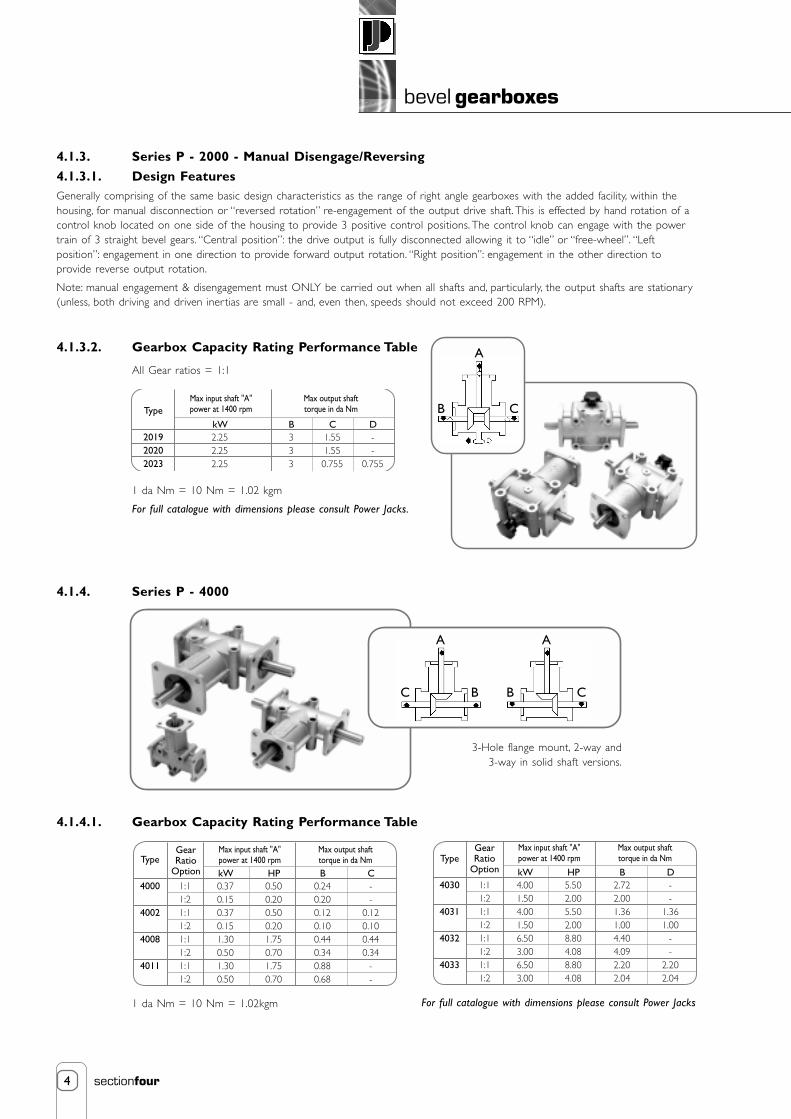
4
bevel gearboxes
sectionfour
4.1.3. Series P - 2000 - Manual Disengage/Reversing
4.1.3.1. Design FeaturesGenerally comprising of the same basic design characteristics as the range of right angle gearboxes with the added facility, within thehousing, for manual disconnection or “reversed rotation” re-engagement of the output drive shaft. This is effected by hand rotation of acontrol knob located on one side of the housing to provide 3 positive control positions. The control knob can engage with the powertrain of 3 straight bevel gears. “Central position”: the drive output is fully disconnected allowing it to “idle” or “free-wheel”. “Leftposition”: engagement in one direction to provide forward output rotation. “Right position”: engagement in the other direction toprovide reverse output rotation.
Note: manual engagement & disengagement must ONLY be carried out when all shafts and, particularly, the output shafts are stationary(unless, both driving and driven inertias are small - and, even then, speeds should not exceed 200 RPM).
4.1.3.2. Gearbox Capacity Rating Performance Table
All Gear ratios = 1:1
1 da Nm = 10 Nm = 1.02 kgm
For full catalogue with dimensions please consult Power Jacks.
4.1.4. Series P - 4000
4.1.4.1. Gearbox Capacity Rating Performance Table
1 da Nm = 10 Nm = 1.02kgm
Type
201920202023
kW2.252.252.25
B333
D--
0.755
C1.551.550.755
Max input shaft "A" power at 1400 rpm
Max output shafttorque in da Nm
Type
4000
4002
4008
4011
1:11:21:11:21:11:21:11:2
kW0.370.150.370.151.300.501.300.50
HP0.500.200.500.201.750.701.750.70
B0.240.200.120.100.440.340.880.68
C--
0.120.100.440.34
--
Max input shaft "A"power at 1400 rpm
Max output shafttorque in da Nm
GearRatio
OptionType
4030
4031
4032
4033
GearRatio
Option
1:11:21:11:21:11:21:11:2
kW4.001.504.001.506.503.006.503.00
HP5.502.005.502.008.804.088.804.08
B2.722.001.361.004.404.092.202.04
D--
1.361.00
--
2.202.04
Max input shaft "A"power at 1400 rpm
Max output shafttorque in da Nm
C
A
BB
A
C
C
A
B
3-Hole flange mount, 2-way and3-way in solid shaft versions.
For full catalogue with dimensions please consult Power Jacks

5
bevel gearboxes
sectionfour
Contents
4. Bevel Gearboxes - Neeter Drive
4.2. Bevel Gearboxes - Neeter Drive - Range - N 64.2.1 Neeter Drive Spiral Bevel Gearbox Characteristics 6
4.2.2 How to Select a Neeter Drive Unit 7
4.2.3 Neeter Drive Technical Data 9
4.2.4 Neeter Drive Gearbox Power Ratings 12
4.2.5 Configuration/Rotation Diagrams for Neeter Drive Gearboxes 13
4.2.6 Neeter Drive Gearbox Dimensions 14
4.2.7 Special Configuration & Features Available from Neeter Drive 18
4.2.8 Neeter Drive Range-N Product Code 19
4.2.9. Neeter Drive Range-N Lubrication & Maintenance Instructions 20
NEETER DRIVES P I R A L B E V E L G E A R B O X E S

6
bevel gearboxes
sectionfour
4.1. Bevel Gearboxes - Neeter Drive - Range - N
4.2.1. Neeter Drive Spiral Bevel Gearbox Characteristics
Neeter Drive Series 35 - 40 Spiral Bevel GearboxesThe NEETER DRIVE gearbox is an ultra compact unit and is available in 5 sizes and 5 gear ratios. The design employs a central bearinghousing support on the 1:1 and 1.5:1 gear ratios, and a small extended bearing housing on the input side of the gearboxes with ratios2:1 and above and hollow shaft output. It is a high torque rated unit with good thermal characteristics. It is available in solid shaft andhollow output shaft configurations and has the option of a motor mounting flange, for easy direct coupling of a standard electric motor.
NEETER DRIVES P I R A L B E V E L G E A R B O X E S
4.2.1.1. Spiral Bevel Gearbox Characteristics
Housing: S.G. Iron to BS27789:1985, Grade 420/12.
Gears: All gears are made from alloy steel and case hardened.
Bearings: Pinion (input) and gear shaft (output) are fitted with twin taper roller bearings to providealmost unchanged backlash over a long life.
Sealing: All units are fitted with spring energised single lipped oil seals and all flanges are sealed byO-rings.
Lubrication: Lubrication is dependent upon the operating conditions, oil for higher speeds and semi fluidgrease for medium and low speeds.
Note: All units are shipped dry from the factory and should be lubricated before use.
Service Life: Life of gears including mountings 10000 hours
Efficiency: Reduction ratio bevel gear units are approximately 95% - 98% efficient. Please consult NeeterDrive regarding increasing ratios.
Overhung Loads: All units are rated for in-line connection. If a unit is to be fitted with a belt pulley, chainsprocket etc., radial forces must be considered. If in doubt please consult Neeter Drive.
Note: Where operating conditions deviate from those described above please consult Neeter Drive.

7
bevel gearboxes
sectionfour
4.2.2. How to Select a Neeter Drive Unit
4.2.2.1. Selecting a Unit Example
When selecting a gearbox, there are a number of factors whichcan influence the final size of unit selected. The informationcontained in the selections gearbox characteristics (4.2.1.) andTechnical data (4.2.3.) provide details of these factors for use inthe selection process.
The following Selection Procedure provides a step-by-stepguide to gearbox selection for those not fully familiar with theprocedures. An example has been used in the selection procedureto assist in following through the procedure.
Specified Information
1. Gearbox Input Speed (rpm) 1. 1000
2. Gearbox Output Speed (rpm) 2. 500
3. Gearbox Configuration (refer Section 4.2.5.) 3. 2 Way (2)
4. Required Output Torque (Nm) 4. 150
5. Operating Hours per Day (refer Section 4.2.3.) 5. 10
6. Input Power Source (refer shock load table) 6. Electric Motor
7. Gearbox Application (refer shock load table) 7. Stacking Machine
8. Number of Starts per Hour (refer Section 4.2.3.3.) 8. 8
9. Transmission Methods 9. Clutch(refer transmission mechanism, Section 4.2.3.5.)
10. Duty Cycle per Hour (% Running time) 10. 35/60 = 58%
11. Operating Ambient Temperature 11. 20o C(refer Thermal Limit, Section 4.2.3.6.)
4.2.2.2. Selection of Design Factors
Step 1 Shock Load Factor (f1 ) Step 1 1.50
Using the Specified Information inPoints 5, 6 and 7 above, select the ShockLoad Factor from the Table in Section 4.2.3.2
Step 2 Starting Frequency Factor (f2 ) Step 2 1.00
Using the Specified Information in Point 8above, select the Starting Frequency Factorfrom the Table in Section 4.2.3.3
Step 3 Transmission Load Factor (f3) Step 3 1.00
Using the Specified Information in Point 9above, select the Transmission Load Factorfrom the Table in Section 4.2.3.4.
Step 4 Thermal Limit - Duty Cycle - Factor (f4) Step 4 1.25
Using the Specified Information in Point 10above, select the Thermal Limit - Duty Cycle- Factor from the Table in Section 4.2.3.6.1.
Step 5 Thermal Limit- Ambient Temperature - Factor (f5) Step 5 1.00
Using the Specified Information in Point 11 above,select the Thermal Limit - Ambient Temperature -Factor from the Table in Section 4.2.3.6.2.
A gearbox is required for an Input Speed of 1000 rpm,an Output Speed of 500 rpm, an Output Torque of 150Nmand one Output Shaft. The Drive is by electric motor througha clutch mechanism and the gearbox is on the main drive ofa heavy duty stacking machine. The machine operates for10 hours per day, starts 8 times per hour and operates for35 minutes in every hour, the other 25 minutes being takenup in loading the machine. The ambient temperature of thepremises is 20°C.
8
bevel gearboxes
sectionfour
4.2.2.3. Calculated Data
Step 6 Calculate the Gear Ratio = Step 6 1000/500 = 2Input Speed ÷ Output Speed Therefore 2:1 Reduction
Note: If the gear ratio does not correspond to one ofthe STANDARD ratios contained in this technicalmanual, one of the speeds, normally the outputspeed, must be changed to bring the ratio tostandard. Non-standard ratios can be supplied, ifrequired, but such special selections must bereferred to Neeter Drive.
Step 7 Calculate the Corrected Output Torque = Step 7 150 x 1.25 x 1.00 x 1.00 = 187.5 NmRequired Output Torque x f1 x f2 x f3
Note: Where there is more than one output shaft,the Required Output Torque for the gearbox isthe summation of the individual Output Torquesfrom the output shafts.
Step 8 Calculate the Corrected Output Power = Step 8 (187.5 x 500) ÷ 9550 = 9.82 kWRequired Output Torque xOutput Speed ÷ 9550
Step 9 Calculate the Input Power = Step 9 9.82 ÷ 0.98 = 10.02 kWOutput Power ÷ Efficiency(Gearbox efficiency is between 95% and 98%after initial running in)
4.2.2.4. Gearbox Selection
Step 10 From the GEARBOX RATINGS TABLE, Step 10 From the Selection Table in Section 4.2.4.,select the gearbox with the closest adequate for Input Power 10.02 kW, gear ratio 2:1,rated Power. Output Torque 315 Nm and Input Speed
1000 rpm, select Series 39.
Step 11 When selecting a gearbox, the Thermal Step 11 From the table in Section 4.2.3.6.3, LimitingCapacity of the gearbox chosen must be Thermal Capacity for Series 39 is 49kW.considered. For the Limiting Thermal Capacity,expressed as a Power Rating, refer to Section4.2.3.6.3. For the selected gearbox, calculate the Calculate the gearbox,Thermal Capacity = Thermal Capacity = 49 x 1.25 x 1.00 = 73.5 kWLimiting Thermal Capacity x f4 x f5.
The Calculated Input Power must not exceed The Input Power is within this limit.this Calculated Thermal Capacity. A larger Selected gearbox is ok.gearbox must be selected if the CalculatedInput Power is higher and a check run on theother parameters
Step 12 As a final check on the capacity of the chosen Step 12 Power transmission is by clutch. From thegearbox, the effect of the connected drive Transmission Load Factor table (refer Sectionsystems must be considered. The section 4.2.3.5), there are no additional loads to beheaded Permissible Shaft Loading describes considered and the selection of gearbox isthe calculation to be undertaken where the acceptable.transmission mechanism can give rise to radialand/or axial forces on the gear shafts. Thisoccurs, particularly, where chain and beltdrives are employed.

9
bevel gearboxes
sectionfour
4.2.3. Neeter Drive Technical Data
4.2.3.1. Capacity and TorqueRefers to the rated capacity and rated torque on the basis of the following nominal values:
• Shock-free operation
• Operating time per day = 8 hours
• Max. 20 starts per hour (torque x 1.5 permissible)
• Duty cycle 100%
• Life of gears including mountings 10000 hours
• When selecting gearboxes please take thermal capacity into consideration.
• Ambient temperature approx. 20° C (-10° to +50°C capacity into consideration permissible)
4.2.3.2. Shock Load Factor (f1)
4.2.3.3. Starting Frequency Factor (f2)up to 20 star ts per hour f2 = 1.0
up to 60 star ts per hour f2 = 1.1
up to 200 starts per hour f2 = 1.3
up to 600 starts per hour f2 = 1.5
more than 600 starts per hour (on request)
4.2.3.4. Transmission Load Factor (f3)The total load on the drive shafts and their bearing is the result of:
a. The loads arising from the gear teeth
b. The axial and radial loads arising from the transmission mechanisms attached to the drive shafts. It is this load whichmust be considered when selection the gearbox and shaft sizes.
Depending upon the type of transmission mechanism used in connecting the gear shafts to the driving and driven loads, axial and / orradial loads can be applied to the gearbox shafts and their bearings. These loads can arise from:
either preload, due for example, to tension loading in beltsor dynamic forces, due for example, to out-of-balance in the transmission element or shock load,due for example, to snatching in a chain drive.
The following table gives the factors which should be used to correct the Output Torque when sizing the gearbox.
IConveyor Belts
GeneratorsVentilators
Light Textile MachineryRotating Machine Tools
IIIPunching Machine
ShearsForging Presses
VibratorsRolling Mills
Extremely Heavy LiftsHeavy Duty Roller Conveyors
IIHeavy Duty Lifts
HoistsMixersCranes
Heavy Duty Textile MachineryWoodworking Machinery
Paper Machinery
Shock Load Category
Electric MotorOperating Time per Day (hrs)
101.001.251.50
≤20.91.001.50
>101.251.501.75
Shock LoadCategory
IIIIII
Single Cylinder Piston MachineOperating Time per Day (hrs)
Piston Machine Hydro MotorOperating Time per Day (hrs)
Input Power Source
101.251.502.00
≤21.001.251.75
>101.501.752.25
101.501.752.25
≤21.251.502.00
>101.752.002.50

10
bevel gearboxes
sectionfour
4.2.3.5. Transmission Load Factor (f3)
4.2.3.6. Thermal LimitsDue to the compact design of this range of spiral bevel gear units the ratings are controlled by the thermal capacity at some speeds. Amaximum case temperature of 80°C is specified and temperatures in excess of this figure normally indicate either incorrect oil levels ortoo much power being handled by the unit. If this temperature is exceeded Neeter Drive should be consulted.
4.2.3.6.1. Thermal Limit - Duty Cycle - Factor (f4)Duty cycle per hour is the percentage of the time per hour during which the gearbox will be on-load.
4.2.3.6.2. Thermal Limit - Ambient Temperature - Factor (f5)
4.2.3.6.3. Limiting Thermal CapacityThe capacity of some gears is limited by the maximum permissible temperature of the oil bath. The charts below show the limitingthermal capacities, which can be transferred without cooling at an ambient temperature of 20°C and duty cycle of 100% per hour.
WARNING: The case temperature must not exceed 80°C, (see thermal limits).
Neeter Drive should be consulted if a gear unit is to be installed with a shaft positioned vertically.
4.2.3.7. Interpreting Power ChartsSpeeds other than those shown may be calculated easily by interpolating between next lower and next higher speeds shown. Theratings are based upon a 10000 hour life datum, (8-10) hours per day operation, uniform power source, free from recurrent shockloads) and must be adjusted by service factor from the factor tables if different.
4.2.3.8. Approximate Gear Box Weight
TransmissionMechanismClutches
Gears of all TypesChains
Flat BeltsV-Belts, Toothed Belts
Preload--
1.00 → 1.252.00 → 2501.50 → 2.00
Dynamic1.00
1.00 → 1.251.25 → 1.501.00 → 1.251.00 → 1.25
Transmission Load Factor (f3)
Duty Cycle per Hour (%)Thermal Limit Factor, f4
1001.00
801.25
601.50
401.75
202.00
Ambient Temperature oCThermal Limit Factor, f5
101.20
201.00
300.87
400.75
500.62
SeriesPower (kW)
353.3
379.0
3820.5
3949
4090
Weight (kg)Series 35Series 37Series 38Series 39Series 40
2 Way1:1 & 1.5:1 Ratio
4.510.52038112
3 Way1:1 & 1.5:1 Ratio
4.7511
20.546.5116
2 Way2:1 & Above
6.5122345
126.5
3 Way2:1 & Above
6.7512.523.553131

11
bevel gearboxes
sectionfour
4.2.3.9. Permissible Shaft LoadingAfter selecting the gearbox for the required duty it is necessary to check that the axial and radial loading arising from the transmissionmechanism is acceptable for the gear shaft diameters on the selected gearbox (gear shaft diameters are given on the Dimensions pagefor the chosen design).
The bearing configuration on the shafting, the shaft diameter and the shaft speed determine the permissible external loading which canbe carried by the shaft without bearing or shaft failure. The graph showing permissible radial forces on shafts has been drawn for atypical Output Shaft. In this arrangement the bearing centres are mounted at either end of the through shaft and there is a significantspan which allows higher radial loads to be accepted, see sketch below. For typical Input Shafts and Output Shafts, which are overhungfrom the gearbox face, the bearing centres are closer together and the radial load carrying capacity is reduced, see sketch below.
To calculate the Permissible Loading on the gearbox shafts, use the gearbox output and input speeds and diameters respectively.
1. Read off the Permissible radial Force for the nearest diameter shafts from the graph below.2. Use the Correction Factors, below, to calculate the Permissible Radial and Axial Loads for each of the gearbox shafts.
4.2.3.10. Correction Factors
Ø10Ø11Ø12
Ø14
Ø16
Ø18
Ø20
Ø22
Ø24
Ø26Ø28Ø30Ø32
Ø35
Ø38Ø40
Ø45Ø50Ø55Ø60Ø65Ø70Ø75Ø80
Ø90
Ø100
Ø1105000060000
40000
30000
20000
15000
1000090008000700060005000
4000
3000
2000
1000
300
200
100
400
500600700800900
200
100 1000 2000
RPM of Shafts d1 and d2 (min-1)
3000 4000
500 750 1500 2500 3500
Shaf
t D
iam
eter
(m
m)
Perm
issi
ble
Rad
ial F
orce
on
Shaf
t d 2
(N
)
The calculated loads should be checked against the radial and axial loads provided by the manufacturer of the transmission mechanism.If the loading created by the transmission mechanism exceeds the permissible level, a gearbox with a larger diameter shaft is required.At this point Neeter Drive should be consulted as it is often possible to fit a special shaft arrangement into a standard gearbox.
Permissible Radical ForcesPermissible Axial Forces
Output Shaft(Bearings on through shaft)
1.000.50
Input Shaft(Bearings on overhung shaft)
0.660.50
Output Shaft(Bearings on overhung shaft)
0.660.50
Gearboxes withCentrebearing
0.400.50
Ratios 2:1 & abovePermissible Shaft Loading Curves
Ratios 1:1 & 1.5:1
Permissible Shaft Loading Curves
Example Series 39, ratio 2:1Shaft diameter = 48 mm, nearest tabulated diameter = 45 mm
Ød1 = 45 (48) permissible transverse force 7000 N x 0.66 = 4620 Npermissible axial force 4620 N x 0.50 = 2310 N
Ød2 = 45 (48) permissible transverse force 8400 N x 1.00 = 8400 Npermissible axial force 8400 N x 0.50 = 4200 N

12
bevel gearboxes
sectionfour
4.2.4. Neeter Drive Gearbox Power Ratings
Power Ratings
Gea
r U
nit
Rat
io10
5010
025
050
075
010
0015
0020
0025
0030
00N
mN
mN
mN
mN
mN
mN
mN
mN
mN
mkW
Nm
kWkW
kWkW
kWkW
kWkW
kWkW
Pow
er R
atin
gs a
t gi
ven
Inpu
t Sp
eeds
(re
v m
in-1
)
Seri
es 3
5
1:1
1.5:
12:
13:
1
75 56 45 17
75 56 37 17
64 39 37 17
58 39 34 17
54 39 30 17
51 37 30 17
46 35 27 17
42 33 27 17
33 26 22 15
32 26 22 15
0.4
0.2
0.12
0.03
94 56 56 28
0.1
0.04
0.03
0.01
0.8
0.4
0.2
0.06
1.7
0.7
0.5
0.15
3.1
1.4
0.9
0.31
4.3
2.1
1.2
0.45
5.4
2.6
1.6
0.6
7.4
3.7
2.2
0.9
8.9
4.7
2.9
1.2
8.9
4.7
2.9
1.3
10.4
5.6
3.6
1.6
Seri
es 3
7
1:1
1.5:
12:
13:
14:
1
187
140
112
62 45
187
112
112
56 37
161
107
97 56 30
144
98 94 45 30
135
94 87 45 30
127
90 84 42 30
115
84 80 39 30
106
81 76 39 28
98 80 76 39 28
95 80 75 39 28
1.0
0.5
0.3
0.11
0.06
187
140
187
84 37
0.2
0.1
0.1
0.03
0.01
2.0
0.8
0.6
0.2
0.1
4.3
1.9
1.3
0.5
0.2
7.7
3.5
2..5
0.8
0.4
10.8
5.0
3.5
1.2
0.6
13.6
6.4
4.5
1.5
0.8
18.5
9.0
6.4
2.1
1.2
22.6
11.5
8.1
2.8
1.5
26.3
14.3
10.1
3.5
1.9
30.6
17.0
12.0
4.2
2.25
Seri
es 3
8
1:1
1.5:
12:
13:
14:
1
468
253
225
168
97
468
225
225
140
86
438
191
195
135
105
397
171
180
124
67
373
163
172
116
65
356
156
168
112
64
328
145
160
107
60
305
136
155
105
60
287
133
154
106
60
-12
915
310
560
2.5
0.9
0.6
0.3
0.13
468
281
562
281
112
0.5
0.2
0.3
0.1
0.03
5.0
1.6
1.2
0.5
0.23
11.7
3.4
2.6
1.2
0.7
21.2
6.1
4.8
2.2
0.9
29.9
8.7
6.9
3.1
1.3
38 11.1
9.0
4.0
1.7
52.6
15.5
12.8
5.7
2.4
65.1
19.4
16.6
7.5
3.2
76.6
23.6
20.6
9.4
4.0
-27
.624
.611
.24.
8
Seri
es 3
9
1:1
1.5:
12:
13:
14:
1
936
477
749
449
299
917
477
674
393
262
831
505
591
359
261
723
531
543
331
217
649
547
517
314
210
589
560
498
306
202
482
576
474
292
192
-58
446
328
819
1
-59
047
028
519
0
- -47
628
419
1
5.0
1.7
2.0
0.8
0.4
936
477
936
562
374
1.0
0.34 0.5
0.2
0.1
9.8
3.4
3.6
1.4
0.7
22.2
9.0
7.9
3.2
1.74
38.6
18.9
14.5
5.9
2.9
52.0
29.2
20.7
8.4
4.2
62.9
39.9
26.6
10.9
5.4
77.2
61.5
38.0
15.6
7.7
-83
.249
.520
.510
.2
-10
562
.825
.412
.7
- -76
.330
.315
.3
Seri
es 4
0
1:1
1.5:
12:
13:
14:
1
3032
2499
2546
1460
1123
2976
2288
2340
1263
1048
2781
2044
2096
1157
1033
2358
1842
1947
1078
876
2071
1700
1867
1041
844
1816
1572
1810
1014
820
-13
5717
3597
378
9
- -16
9495
978
8
- -16
9295
778
6
- - -95
578
4
16.2
8.9
6.8
2.6
1.5
3088
2667
2808
1965
1497
3.3
1.9
1.5
0.7
0.4
31.8
16.3
12.5
4.5
2.8
74.3
36.4
28 10.3
6.9
126
65.6
52.0
19.2
11.7
166
90.8
74.8
27.8
16.9
194
112
96.7
36.1
21.9
-14
513
952
.031
.6
- -18
168
.342
.1
- -22
685
.252
.5
- - -10
262
.8
Rat
ings
with
in t
he b
orde
red
area
– c
heck
the
r mal
lim
it!

13
bevel gearboxes
sectionfour
4.2.5. Configuration/Rotation Diagrams for Neeter Drive Gearboxes
Ratios 1:1 & 1.5:1
Ratios 2:1 & Above
Hollow Shaft - All Ratios
Side 4
Side 1(input side as standard)
Side 6
Side 2
Side 3
Side 5
2 (2 Way) 5 (2 Way Reverse) 3 (3 Way) 4 (3 Way Reverse) 7 (4 Way)
2 (2 Way) 5 (2 Way Reverse) 3 (3 Way) 4 (3 Way Reverse) 7 (4 Way)
K (2 Way) L (2 Way Reverse) O (3 Way) J (4 Way)

14
bevel gearboxes
sectionfour
4.2.6. Neeter Drive Gearbox Dimensions
4.2.6.1. Gear Unit Dimensions - Ratios 1:1 and 1.5:1 Solid Shafts
Note: 1. All dimensions in mm unless otherwise stated.2. Dimensions subject to change without notice
G
H
B
OilPlug
E
J
OilPlug
OilPlug
Ød 1
4 Mounting Holeson Sides 5 and 6,K x M Deep
B
ECF
A
N P(Keyway)
J
B B
Tapped Hole in End of Each Solid Drive Shaft - Detail ‘V’
Series3537383940
A90130156198280
B36.5545776114
C6490104134165
Ød 1(js6)1924324860
E45657899140
F105140165210267
G92105143
190.5292
H46
52.571.595.25146
J
41506176102
KM8M10M10M12M16
M1220202530
N245
2.55
P key to BS4235Part 1:19726 x 6 x 368 x 7 x 4010 x 8 x 5014 x 9 x 7018 x 11 x 90
VM6 x 16 mm DeepM8 x 25 mm DeepM10 x 25 mm DeepM12 x 30 mm DeepM16 x 38 mm Deep

15
bevel gearboxes
sectionfour
4.2.6.2. Gear Unit Dimensions - Ratios 2:1 and Above Solid Shafts
** See Series 40 extended input housing detail
Note: 1. All dimensions in mm unless otherwise stated.2. Dimensions subject to change without notice
G
H
B
OilPlug
E
J
OilPlug
OilPlug
Ød 1
4 Mounting Holeson Sides 5 and 6,K x M Deep
B
ECF
A
N P(Keyway)
J
B B
Tapped Hole in End of Each Solid Drive Shaft - Detail ‘V’
Series3537383940
A90130156198280
B36.5545776114
C6490104134165
Ød 1(js6)1924324860
E45657899140
F105140165210267
G92105143
190.5292
H46
52.571.595.25146
J
41506176102
KM8M10M10M12M16
M1220202530
N245
2.55
P key to BS4235Part 1:19726 x 6 x 368 x 7 x 4010 x 8 x 5014 x 9 x 7018 x 11 x 90
VM6 x 16 mm DeepM8 x 25 mm DeepM10 x 25 mm DeepM12 x 30 mm DeepM16 x 38 mm Deep
ØR617892118
152**
S143203222299388
S
ØR
ØR
Series 40

16
bevel gearboxes
sectionfour
4.2.6.3. Gear Unit Dimensions - All Ratios Hollow Output Shafts
** See Series 40 extended input housing detail
Note: 1. All dimensions in mm unless otherwise stated.2. Dimensions subject to change without notice
Series3537383940
A90130156198280
B36545776114
C6490104134165
Ød 1(js6)1924324860
E45657899140
F6793107137168
G92105143
190.5293
H46
52.571.595.25146
J
41506176102
KM8M10M10M12M16
M1220202530
N68101418
P key to BS4235Part 1:19726 x 6 x 368 x 7 x 4010 x 8 x 5014 x 9 x 7018 x 11 x 90
VM6 x 16 mm DeepM8 x 25 mm DeepM10 x 25 mm DeepM12 x 30 mm DeepM16 x 38 mm Deep
Ød 2H71924324860
ØR617892118
152**
S143203222299388
T key to BS4235Part 1:19726 x 6 x 1348 x 7 x 18610 x 8 x 21414 x 9 x 27418 x 11 x 336
G
H
B
OilPlug
E
OilPlug
OilPlug
Ød 1
4 Mounting Holeson Sides 5 and 6,K x M Deep
B
ECF
A
J
B B
Tapped Hole in End of Each Solid Drive Shaft - Detail ‘V’
S
ØR
ØR
Series 40
N
(Key
way
)
P
Ød 2T(Keyway)

17
bevel gearboxes
sectionfour
4.2.6.4. Gear Unit Dimensions - Motor Mounting Flanges
Notes: 1. All other gearbox dimensions are as detailed in Sections 4.2.6.1, 4.2.6.2 and 4.2.6.32. All Flange dimensions conform to standard IEC electric motor details3. NEMA flanges available on request.
Should you require a unit outside of, or a deviation from our standard product, Neeter Drive’s design team is alwaysavailable to assist in producing a unit to meet your specific requirements. Do not hesitate to contact us with yourapplication details.
Note: 1. All dimensions in mm unless otherwise stated.2. Dimensions subject to change without notice.
A
Motor FrameD71D80D90D100D100D112D112D112D132D132D160D160D160D160D180D180D180D200
D225 : 2 PoleD225 : 4 - 8 Pole
D250 : 2 Pole
Fear Unit PrefixABCDDDDDEEFFFFGGGHJKL
Dimension 'A'115115130130140130140190190220190210220240220240280280280310310
RatioAllAllAll
1:1 and 1.5:12:1
1:1 and 1.5:12:1AllAllAll
1:1, 1.5:1 and 2:13:1 and 4:1
1:1, 1.5:1 and 2:13:1 and 4:1
1:1, 1.5:1 and 2:13:1 and 4:1
AllAllAllAllAll
Gear Unit Series353537373737373838393838393939394040404040
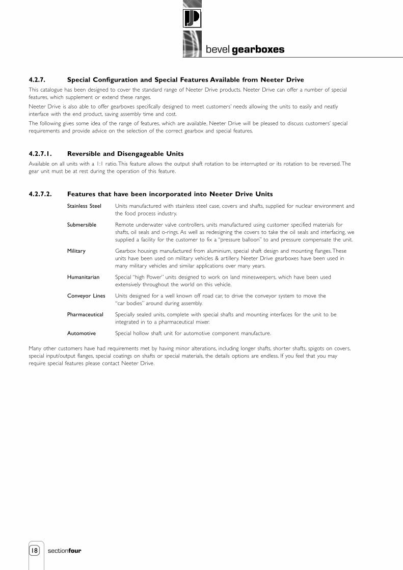
18
bevel gearboxes
sectionfour
4.2.7. Special Configuration and Special Features Available from Neeter DriveThis catalogue has been designed to cover the standard range of Neeter Drive products. Neeter Drive can offer a number of specialfeatures, which supplement or extend these ranges.
Neeter Drive is also able to offer gearboxes specifically designed to meet customers’ needs allowing the units to easily and neatlyinterface with the end product, saving assembly time and cost.
The following gives some idea of the range of features, which are available, Neeter Drive will be pleased to discuss customers’ specialrequirements and provide advice on the selection of the correct gearbox and special features.
4.2.7.1. Reversible and Disengageable UnitsAvailable on all units with a 1:1 ratio. This feature allows the output shaft rotation to be interrupted or its rotation to be reversed. Thegear unit must be at rest during the operation of this feature.
4.2.7.2. Features that have been incorporated into Neeter Drive Units
Stainless Steel Units manufactured with stainless steel case, covers and shafts, supplied for nuclear environment andthe food process industry.
Submersible Remote underwater valve controllers, units manufactured using customer specified materials forshafts, oil seals and o-rings. As well as redesigning the covers to take the oil seals and interfacing, wesupplied a facility for the customer to fix a “pressure balloon” to and pressure compensate the unit.
Military Gearbox housings manufactured from aluminium, special shaft design and mounting flanges. Theseunits have been used on military vehicles & artillery. Neeter Drive gearboxes have been used inmany military vehicles and similar applications over many years.
Humanitarian Special “high Power” units designed to work on land minesweepers, which have been usedextensively throughout the world on this vehicle.
Conveyor Lines Units designed for a well known off road car, to drive the conveyor system to move the“car bodies” around during assembly.
Pharmaceutical Specially sealed units, complete with special shafts and mounting interfaces for the unit to beintegrated in to a pharmaceutical mixer.
Automotive Special hollow shaft unit for automotive component manufacture.
Many other customers have had requirements met by having minor alterations, including longer shafts, shorter shafts, spigots on covers,special input/output flanges, special coatings on shafts or special materials, the details options are endless. If you feel that you mayrequire special features please contact Neeter Drive.

19
bevel gearboxes
sectionfour
4.2.8. Neeter Drive Range - N Product CodeEach Neeter Drive Gear Unit is allocated a Part Number which defines the unit specification. For identification purposes this number isstamped on each unit.
The following chart outlines the Part Numbering System. It should be noted that as Neeter Drive’s range of units has developed overthe years, cer tain features are not applicable to the current range.
* Non Standard feature
** Not available on Series 35
† Reverse/Reversible ConfigurationThe reverse configuration is the way in which the output shaft rotates (refer Section 4.2.5)The Reversible unit has a hand wheel on the unit so the output shaft direction of rotation (refer Section 4.2.5) can bechanged when stationary.
1. MOTOR MOUNTING FLANGES - No Motor Flange (leave blank)A-L Motor Flange
(Refer to Section 6.4 formotor identification letter)
2. GEAR UNIT TYPE35, 37, 38, 39 40
3. CONFIGURATION0 3 Way Hollow Shaft1 In Line 2 Way2 2 Way3 3 Way4 3 Way Reverse5 2 Way Reverse6 3 Way Reversible * †7 4 Way8 2 Way Disengageable *9 5 Way (Special)A 3 Way Disengageable * †C 2 Way Reversible *H 2 Way Reverse Disengageable *J 4 Way Hollow ShaftK 2 Way Hollow ShaftL 2 Way Reverse Hollow Shaft
4. GEAR TYPE3 Straight Bevel *4 Spiral Bevel
8. SPECIAL FEATUREA unique suffix is allocated by Neeter Drive to define special features. (3 to 7 character code).
7. ISSUE NoInternal Numbering System Only
6. VERSIONM Metric Shaft Version (mm)E Imperial Shaft Version (ins) *
5. EXACT GEAR RATIOS1 1 to 1 Ratio Gears1.5 1.5 to 1 Ratio Gears2 2 to 1 Ratio Gears3 3 to 1 Ratio Gears4 4 to 1 Ratio Gears * *
Character
Example
1 2 3 4 5 6 7 8 9 - 15
38 4 4 2 M 5 XXX

20
bevel gearboxes
sectionfour
4.2.9. Neeter Drive Range - N Lubrication and Maintenance Instructions
4.2.9.1 Installation1. Gear units are shipped dry.
2. Check your gear unit for damage during shipment.
3. Take care when fitting couplings, a blow on a shaft end can cause gear overmeshing.
4. Shaft alignment is critical, check on installation.
4.2.9.2. Oil LevelsThe information given below assumes that the gear unit is positioned with all shafts in a horizontal plane.
For input speeds up to 1500 RPM the oil level in the gear unit should be maintained just below the centreline of the shafts. A sightglass or level plug is provided for level indication.
A change of oil level may be required for speeds of 1500 RPM or above, and Neeter Drive should be consulted.
For input speeds of 250 rpm or below grease lubrication should be used.
Important Neeter Drive should also be advised when a gear unit is installed with a shaft positioned vertically.
4.2.9.3. Case TemperatureBevel units will operate with a maximum case temperature of 80°C. If this temperature is exceeded Neeter Drive should be consulted.
4.2.9.4. Maintenance InstructionsA new gear unit should be drained after 100 hours and cleaned using a light flushing oil. After this the gear unit oil should be changedevery six months or 2500 operating hours. Where severe operating conditions are encountered more frequent oil changes are advised.The gear unit should be warm when an oil change is undertaken. Check oil levels regularly.
Warning: The case temperature must not exceed 80°C (See case temperature)
4.2.9.5. Oil SpecificationAmbient Temperature Gear Oil
Below +5°C ISO 150 Mobilgear 629 or equivalent
+5°C to +40°C ISO 220 Mobilgear 630 or equivalent
Above 40°C ISO 320 Mobilgear 632 or equivalent
Fill quantities (Average)
4.2.9.6. Grease Nipples/Grease Filled UnitsUse EP1 Grease e.g. Mobilux EP1 or equivalent
4.2.9.7. SparesWhen ordering spares always specify the part number and serial number stamped on the gear unit.
Series NoLitresPints
350.140.24
370.290.50
380.751.32
391.713.00
403.275.75

21
bevel gearboxes
sectionfour
Contents
4. Bevel Gearboxes - Neeter Drive
4.3. Bevel Gearboxes - Neeter Drive - Range - BA 224.3.1. BA Gearbox Features 22
4.3.2. BA Gearbox Mounting 22
4.3.3. Performance of BA Spiral Bevel Gearboxes 23
4.3.4. BA Gearbox Selection 24
4.3.5. BA Gearbox Dimensions 25
4.3.6. Standard BA Series Gearbox Selection 26
NEETER DRIVES P I R A L B E V E L G E A R B O X E S

22
bevel gearboxes
sectionfour
4.3. BA - Series Cubic Spiral Bevel Gearboxes
4.3.1. BA Gearbox Features• Robust cast iron construction.
• Cuboid body shape - good symmetry.
• Universal mounting on all sides.
• 10 gearbox sizes.
• 6 standard ratios from 1:1 to 6:1.
• Special ratios available on request.
• Torque range 10 Nm to 9000 Nm.
• High quality bearings giving long life.
Neeter Drives range of Cubic spiral bevel gear boxes are produced in a modular design with many standard models covering a wideperformance range. The modular design allows multi-shaft and power take off drives. Standard units have two or three shafts althoughmore are available on special request, consult Neeter Drives. All the gearboxes can be driven by either input or output shafts toincrease or decrease in speed and all the gearboxes can be supplied with flanges to suit direct mounting of standard IEC frame motors.
4.3.2. BA Gearbox MountingThe spiral bevel gearboxes are supplied with tapped mounting holes in all faces however the following must be considered.
1. Grease Lubrication - No breather or sightglass required. The gearbox can be mounted in any orientation.
2. Oil Lubrication - Breather, sightglass and drain plug required. The gearbox can be mounted in any orientation butthe side of the gearbox facing downwards “side-under” and the side in which the sightglass and breather arerequired must be stated when ordering. Note breathers and sightglasses cannot be fitted on the same face as theshaft.
• Input Shaft Bearings - are supported by high qualityball bearings up to size 2, and taper roller bearings upto sizes 23 to 6.
• Output Shaft Bearings - are supported by deep groove ballbearings to withstand high radial loads and give long life.
• Gearbox Housing - produced in quality grey cast ironensuring strength and stability.
• Alloy steel gears - hardened and lapped in pairs then set inthe gearbox to give the optimum setting for quiet efficientrunning.
Series - LSolid Through Shaft
Series - HHollow Shaft
Series - KSolid Shaft IndependentBearings for each Shaft.
Motor FlangesStandard IEC MotorFrames (B5 and B14).
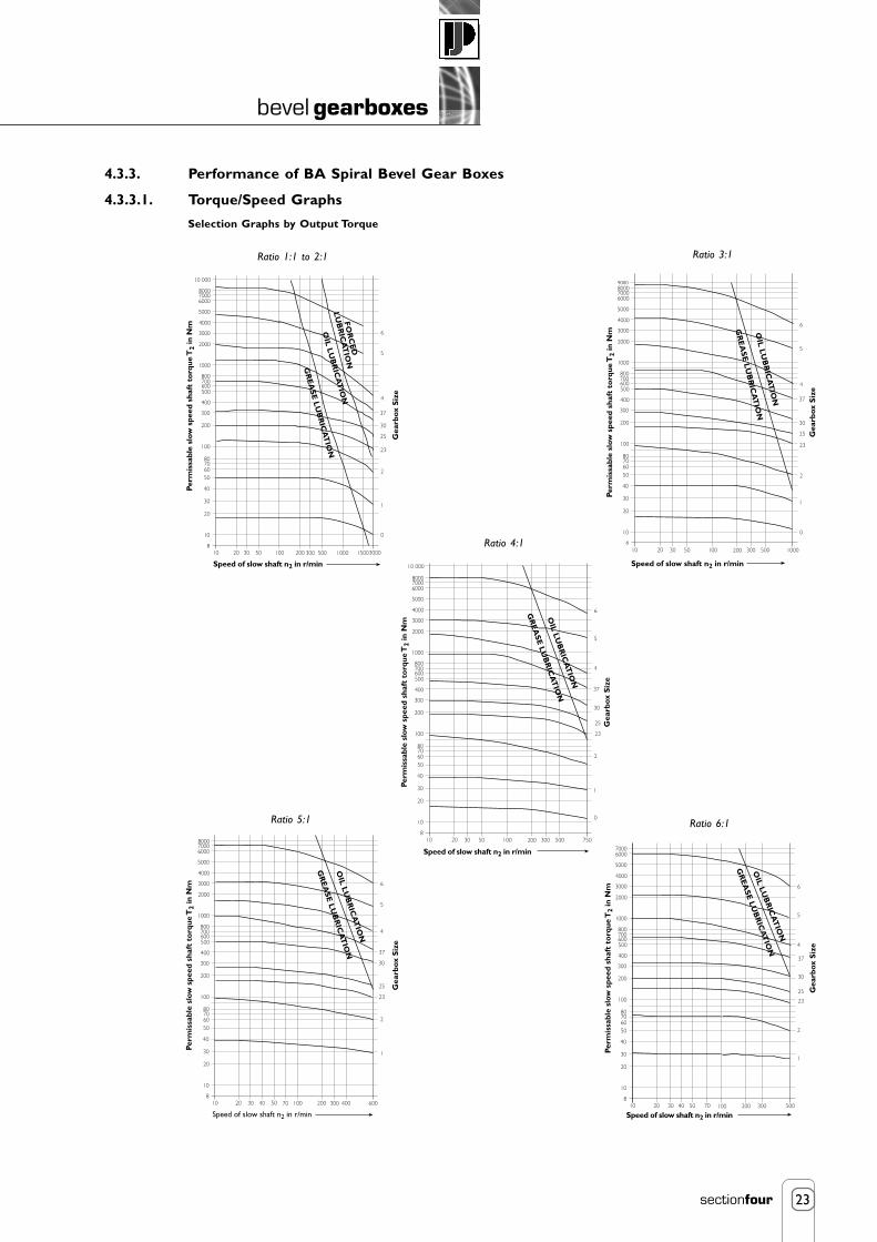
23
bevel gearboxes
sectionfour
4.3.3. Performance of BA Spiral Bevel Gear Boxes
4.3.3.1. Torque/Speed Graphs
Speed of slow shaft n2 in r/min
Perm
issa
ble
slow
spe
ed s
haft
to
rque
T2
in N
m
10 20 30 100 200 1000 150050 300 500 30008
10
20
30
40
50607080
100
200
300
400
500600700800
1000
2000
3000
4000
5000
600070008000
10 000
0
1
2
23
25
30
37
4
5
6
Gea
rbox
Siz
e
FOR
CE
D
LU
BR
ICA
TIO
N
OIL
LU
BR
ICA
TIO
N
GR
EA
SE L
UB
RIC
AT
ION
Selection Graphs by Output Torque
1000
Speed of slow shaft n2 in r/min
Perm
issa
ble
slow
spe
ed s
haft
to
rque
T2
in N
m
108
10
20
30
40
50607080
100
200
300
400
500600700800
1000
2000
3000
4000
5000
6000700080009000
0
1
2
23
25
30
37
5
6
Gea
rbox
Siz
e
20 30 50 100 200 300 500
4
OIL
LU
BR
ICA
TIO
N
GR
EA
SE L
UB
RIC
AT
ION
750
Speed of slow shaft n2 in r/min
Perm
issa
ble
slow
spe
ed s
haft
to
rque
T2
in N
m
108
10
20
30
40
50607080
100
200
300
400
500600700800
1000
2000
3000
4000
5000
600070008000
10 000
0
1
2
23
25
30
37
5
6G
earb
ox S
ize
20 30 50 100 200 300 500
4
OIL LU
BR
ICA
TIO
N
GR
EA
SE LU
BR
ICA
TIO
N
Ratio 1:1 to 2:1 Ratio 3:1
Ratio 4:1
Ratio 5:1
600
Speed of slow shaft n2 in r/min
Perm
issa
ble
slow
spe
ed s
haft
to
rque
T2
in N
m
108
10
20
30
40
50607080
100
200
300
400
500600700800
1000
2000
3000
4000
5000
600070008000
1
2
23
25
30
37
5
6
Gea
rbox
Siz
e
20 30 40 70 200 300
4
50 100 400
OIL LU
BR
ICA
TIO
N
GR
EA
SE LU
BR
ICA
TIO
N
500
Speed of slow shaft n2 in r/min
Perm
issa
ble
slow
spe
ed s
haft
to
rque
T2
in N
m
108
10
20
30
40
50607080
100
200
300
400
500600700800
1000
2000
3000
4000
5000
60007000
1
2
23
25
30
37
5
6
Gea
rbox
Siz
e
20 30 40 70 200 300
4
50 100
OIL LU
BR
ICA
TIO
N
GR
EA
SE LU
BR
ICA
TIO
N
Ratio 6:1

24
bevel gearboxes
sectionfour
4.3.3.2. Gearbox Efficiency
4.3.3.3. Radial LoadsThe tables show the maximum radial loads in kN by gearbox type and the individual shafts. Details of axial load capacity on request.Interpolate intermediate values. Below 50 rpm the load capacity remains constant.
Radial Force, Fr
=
Where T = gearbox output torque in Nmfz
= factor from table opposited = p.c.d. in mm of gear, sprocket
4.3.4. SelectionCalculate the power capacity require for the gearbox P (kW) = P
d (kW) x F
L x F
T
Where Pd
= Power required to drive the machine.F
L= Load factor (refer to table)
FT
= Temperature factor (refer to table)
Then calculate the slow shaft torque required, T2.
Slow shaft torque, T2 (Nm) =
Select a gearbox using the torque selection charts for the appropriate gear ratio.
Note Standard gearboxes are grease lubricated and should not exceed a case temperature of 90ºC (194ºF).Consult Neeter Drives for higher temperatures.
Load Characteristics of the machine
Class 1 Uniform load (torque change + 10%) no masses to be accelerated.
Class 2 Medium shocks, short term overload (torque change + 25%) larger masses to be accelerated.
Class 3 Heavy shocks, short term overload (torque change + 100%) very large masses to be accelerated.
Size
Efficiency
0
0.80
1-23
0.90
25-4
0.95
5 & 6
0.96
Factor fz1.12
1.25 - 1.4
1.5 - 2.0
2.0 - 2.5
2.5 - 3
Transmission element
Gears
Chain sprockets
V-Belt pulleys
Flatbelt pulleys with jockey pulley
Flatbelt pulleys without jockey pulley
2000 x T x fz
d
Temperature
10°C20°C30°C40°C50°C
Temperature Factor, FT
0.85
1.0
1.1
1.2
1.4
9550 x P(kW)Gearbox Output Speed
Shaft Speed(rpm)
50
200
1000
3000
0.51
0.39
0.25
0.18
0.8
0.67
0.4
0.3
0.78
1.57
0.39
0.29
1.5
1
0.68
0.49
1.4
0.77
0.57
0.45
2.2
1.6
1
0.75
2
1.4
0.9
0.7
3.8
2.6
1.6
1.3
3.2
2.3
1.5
1.1
6.5
4.2
2.8
2.1
5.5
4
2.8
1.9
9.9
6.9
4.2
3.1
11
7.2
4.8
3.7
15.5
9
6.5
4.8
20
15
8
6.8
28
18
12
8.5
40
28
18
15
40
29
18
15
55
40
28
19
70
49
30
-
OD1
1D2 D1 D2 D2 D2 D2 D2 D2 D2 D2 D2
2D1
23D1
25D1
30D1
37D1
4D1
5D1
6D1
Hours per day
1,71,61,51,41,31,21,11,05
1
1,8
1,7
24 8Load Factor, FL16
1,91,71,81,6
1,51,41,31,2
1,1
1,6
1,5
1,4
1,30 100 200 300 400 500 600 700 800 1000 1200Starts/hr
Class 3
Class 2
Class 1
900

25
bevel gearboxes
sectionfour
4.3.5. BA Gearbox Dimensions - Series L
Note: All dimensions in mm.Dimensions subject to change without notice.
* Side C is output in speed increasing application for ratios over 1:1
BA30 BA40 BA50
Type
L1
L23
L25
L30
L37
L4
L5
L6
1 to 23 to 41 to 2
34 & 61 to 2
34
5 & 61 to 2
34 to 61 to 2
34 to 61 to 23 & 45 & 61 to 23 to 61 to 23 to 61 to 2
34
5 & 61
1.5 to 23
4 to 56
12
1812122520201532282435282442352855406045
80 k665 k660 k655 k6
9090757060
12
18
25
32
35
42
55
60
80 K6
90
7287858595115115125125128128143150150170
190
213228
265
385
445415415415415
100115122122132162162172162180180195212212232273261261305310380360570540540510600570540540530
GearRatio
B D1j6
D2j6
E F Lh7
Kf7
35
45454535
50
60
806868908011090170140140110150150120120110
P1 P2
60
80808070959585110100100120120110150120
160
-
-
T
LO
L2
A
190
274
320
406
454
570
820
940
144
244
90
140
160
200
230
260
350
450
65
120
C
45
70
80
100
115
130
175
225
32.5
60
H
55
85
95
120
132
150
200
250
42
75
I
M8
M10
M12
M12
M16
M16
M20
M20
M6
M10
M
55
85
95
117
135
150
215
245
42
72
N
95
137
160
203
227
285
410
470
72 26
122
R
70
110
120
160
180
220
285
360
45
S
75
-
135
175
-
230
-
-
V
54 44 2
3
-
3
3
-
20
20
-
2
100 100
35
50
60
80
90
110
170
150
26
45
60
-
110
120
-
180
200
-
44
80
-
135
-
-
225
-
345
445
-
-
B
B
R
IØ
Side ESide F
Side C(Input) *
Side C
R
Side ESide F
Side D
Side D
ØL
Sizes L0, 1, 2, 25, 30, 4
Sizes L23, 37, 5, 6
AN N
M MRV
P2 P2
IØ
Side BSide A
Side D
4 Holes ØIon S pcd
D2
D2
KC
HEF
TB
D1
P2Side C
ØS

26
bevel gearboxes
sectionfour
4.3.6. Standard BA Series Gearbox Selection
10
20
30
40
70
80
50
60
Type L
Type H
Type K
Size
0
1
2
23
25
30
37
Ratio
1:1
1.5:1
2:1
3:1
4:1
5:1
6:1
Example
L 23 BA 30 2
TypeSize
SeriesStyle
Ratio

27
bevel gearboxes
sectionfour
Contents
4. Bevel Gearboxes - Neeter Drive
4.4. Bevel Gearboxes - Neeter Drive - Range - PowerGear 284.4.1. Features of PowerGear Bevel Gearbox 28
4.4.2. Neeter Drive PowerGear Performance Ratings 29
4.4.3. Examples of PowerGear Bevel Gearbox Arrangements 30
4.4.4. PowerGear Selection Procedure 30
NEETER DRIVES P I R A L B E V E L G E A R B O X E S

28
bevel gearboxes
sectionfour
4.4. Neeter Drive PowerGear Range
Studies of many applications covered by our bevel gearboxes have been taken into account in the design of the new PowerGear range.The PowerGear a consistently designed new series has been produced to meet with a specific torque/speed spectrum. The advantagesof this approach are:
• The compact and rigid design assures highest performance in a small footprint.
• Lubricated for life, the gearboxes are, depending on their size, maintenance free,if operated under normal conditions.
• Fretting-free torque transfer using a friction locked fit between shaft and bevel gear.
4.4.1. Features of PowerGear Bevel Gearbox• Housings and flanges manufactured from robust
Spheroidal Graphite (SG) iron.
• 8 Gearbox sizes.
• 6 standard ratios from 1:1 to 5:1.
• 2-way, 3-way and 4-way.
• Solid Shafts and Hollow Shafts.
• Motor Adaptors.
• Torque range from 25Nm → 5200Nm.
• Input speeds up to 6500rpm.
• Universal mounting on all sides.
• High quality taper roller bearings giving longoperational life.
• Optimised gear tooth pattern during assemblygiving uniform load distribution.
• The high efficiency of the gearbox, 98%, reducesenergy costs.
• More than 45% of volume economised.
• More than 100% more performance at sameconstruction size.
• More than 60% of weight economised.
• Maintenance Free.
The main advantages of the PowerGear design will be found in applications with requirements of high torque at medium to high speeds,robust unit in a small size, useable in any mounting/working position. Typical applications for the PowerGear are angular torque transferand torque distribution in single, or multiple shaft configurations. In non-stationary applications where weight is extremely important, thePowerGear design is the ideal solution. For applications requiring a 1:1 ratio unit capable of handling greater torque than the standardPowerGear a higher rated “X” range is available utilising the same size cases.

29
bevel gearboxes
sectionfour
4.4.2. Neeter Drive PowerGear Performance Ratings
Operating temperature: -30°C → +100°C
Service Life > 15000 hours (when correctly installed and operated within capabilities).
The maximum allowable oil bath temperature limits the gearbox performance. The required effective performance must not exceed thelimit values allowed for continuous duty.
If on intermittent duty or in the event of increased ambient temperatures, the following factors can be applied as guide values for thedetermination of the related allowable thermal performance limit.
For all the PowerGear gearbox details request a full catalogue from Neeter Drive
Duty cycle per hour in %
Factor
100
1.0
80
1.2
60
1.4
40
1.6
20
1.8
Ambient temperature oC
Factor
10
1.20
20
1.00
30
0.87
40
0.75
50
0.62
1:1
1.5:1
2:1
3:1
4:1
5:1
Max Speed
at 2%Max Load
AllowableRadial Load (N)
Weight (kg)
Thermal
P75
45
68
45
68
42
63
33
50
28
42
25
38
6500
6 to 15
5 to 6
900
1100
450
550
4.5
5.5
P90
78
117
78
117
68
102
54
81
52
78
40
60
5500
6 to 14
4 to 6
1300
1600
650
800
8
7.4
P110
150
225
150
225
150
225
120
180
100
150
85
128
4500
6 to 13
4 to 6
2000
2500
1000
1250
13
10.8
P140
360
540
360
540
330
495
270
405
224
336
196
294
3500
6 to 13
3 to 6
3500
4500
1750
2250
22
16.1
P170
585
878
585
878
544
816
450
675
376
564
320
480
3000
6 to 12
3 to 6
5000
6000
2500
3000
38.5
23.4
P210
1300
1950
1300
1950
1220
1830
1020
1530
860
1290
740
1110
2200
6 to 12
3 to 6
8500
10500
4250
5250
71
28.6
P240
2150
3225
2150
3225
2010
3015
1650
2475
1410
2115
1210
1815
2000
6 to 12
3 to 6
11000
15000
5500
7500
103.5
45.3
P280
3200
4800
3200
4800
3050
4575
2850
4275
2300
3450
2000
3000
1700
6 to 11
3 to 6
15000
18000
7500
9000
155
60.3
Output Torque, M2 (Nm)
Max Torque M2*
Output Torque, M2 (Nm)
Max Torque M2*
Output Torque, M2 (Nm)
Max Torque M2*
Output Torque, M2 (Nm)
Max Torque M2*
Output Torque, M2 (Nm)
Max Torque M2*
Output Torque, M2 (Nm)
Max Torque M2*
Input Speed, N1 (rpm)
Standard OutputBacklash (arcmin)
Minimum OutputBacklash (arcmin)
Input Shaft d1
Output Shaft d2
Input Shaft d1
Output Shaft d2
Performance Limit (kW)
PowerGear
AllowableAxial Load (N)

30
bevel gearboxes
sectionfour
4.4.3. Examples of PowerGear Bevel Gearbox Arrangements
4.4.4. Neeter Drive PowerGear Selection Procedure(a) Make initial gearbox selection based on defined information about the application:
Performance required P (kW) at ninput
(rpm)
Note: Pinput
≈ Poutput
at efficiency of 98% approximately.
Input speed required (rpm).
Output speed required (rpm).
Duty cycle required (ED).
Ambient Temperature.
Gear Ratio = input speed (ninput
) / output speed (noutput
)
Select nearest gear ratio to the exact calculated value.
Output Torque Moutput
(Nm) = (9550 * Poutput
)/noutput
(b) Check Performance Capabilities
Check that output torque required is less than gearbox torque rating.
Moutput
≤ Nominal Torque M2nominal
Check speed rating
Speed n input ≤ Speed N1max
Check Thermal Performance Rating of gearbox.
Performance P ≤ thermal performance limit Ptherm
Check Radial and Axial load rating of gearbox
Radial and axial shaft loads ≤ allowable values.
Note: Force contact point on shaft is the middle of the shaft.

5. reduction gearboxes
Power capacity up to 45 kWOutput torque capacity up to 10000 NmSolid shaft (single and double) and hollow shaftMotorised or gear heads.Foot and flange and shaft mount availableStandard double reduction gear ratios up to 250:1Up to quintuplet reduction available
Section 5.2. - Helical Worm ReductionGearboxes
Power capacity up to 90 kWOutput torque capacity up to 11000 NmSolid shaftMotorised or gear headsFoot and flange mount available.Standard double reduction gear ratios up to 70:1Up to quintuplet reduction available
Section 5.3. - In-line Helical ReductionGearboxes
Helical Worm Gearboxes up to 45 kWIn-Line Helical Gearboxes up to 90 kWParallel Helical Gearboxes up to 18.5 kWWorm Gearboxes up to 140 kW
Section 5.1. - Reduction Gearbox Range
POWER JACKSGroupmanufacturers of precision screw jacks, actuators and gearboxes
1
reduction gearboxes
sectionfive
Contents
5. Reduction Gearboxes
5.1. Reduction Gearboxes - Range 25.1.1. Listed Reduction Gearboxes 2
5.1.2. Reduction Gearboxes Also Available 2
5.2. Helical Worm Reduction Gearboxes 35.2.1. Gearbox Selection 3
5.2.2. Helical Worm Reduction Gearbox Performance 3
5.2.3. Helical Worm Gearbox Output Speeds and Gear Ratios 4
5.2.4. Helical Worm Gearbox Dimensions 5
5.3. In-Line Helical Reduction Gearboxes 75.3.1. Gearbox Selection 7
5.3.2. In-Line Helical Reduction Gearbox Power Rating Guide by Motor Frame Size 7
5.3.3. In-Line Helical Gearbox Torque Ratings 8
5.3.4. In-Line Helical Gearbox Dimensions - Foot Mounted 9
5.3.5. In-Line Helical Gearbox Dimensions - Flange Mounted 10

2
reduction gearboxes
sectionfive
5.1. Reduction Gearboxes - Range
Power Jacks offers a wide range of reduction gearboxes for actuator system building whether it be a single motorised actuator orseveral actuators mechanically linked. The gearboxes are available as motorised units as standard, however the gearbox unit itself can besupplied. This design guide lists the most popular types of gearboxes for actuator system building with many more available on requestfrom Power Jacks.
5.1.1. Listed Reduction GearboxesHelical Worm GearboxesPower capacity up to 45 kW.Output torque capacity up to 10000 Nm.8 Gearbox sizes available.Double Reduction standard up to 250:1 gear ratio.Up to Quintuple reduction available on request.Foot, Flange and Shaft mounting.
In-Line Helical GearboxesPower capacity to 90 kW.Output torque capacity to 11000 Nm.9 Gearbox sizes available.Double Reduction standard up to 70:1 gear ratio.Up to Quintuple reduction available on request.Foot and flange mounting.
5.1.2. Reduction Gearboxes Also AvailableParallel Helical GearboxesPower capacity to 18.5 kW.Output torque capacity to 2900 Nm.4 Gearbox sizes available.Double Reduction standard up to 100:1 gear ratio.Up to Triple reduction available on request.Foot, Flange and Shaft mounting.
Worm Gearboxes Small SizePower capacity to 11 kW.Output torque capacity to 1000 Nm.6 Gearbox sizes available.Single Reduction standard up to 70:1 gear ratio.Double reduction available on request.Foot, Flange and Shaft mounting.
Worm Gearboxes Medium SizePower capacity to 140 kW.Output torque capacity to 10000 Nm.4 Gearbox sizes available.Single Reduction standard up to 70:1 gear ratio.Double reduction available on request.Foot, Flange and Shaft mounting.
The gearboxes can take either IEC or NEMA standard motors. This allows the fitment of brake motors, flame proof motors, DC motors,AC inverter rated motors and energy efficient motors. All the gearboxes are dimensionally interchangeable with major Europeangearbox manufacturers. The advanced design, high grade materials and quality manufacture of the gearboxes are maximised by the highinternal efficiency to ensure a trouble free operational life with simple maintenance routines kept to an absolute minimum.

3
reduction gearboxes
sectionfive
5.2. Helical Worm Reduction Gearboxes
5.2.1. Gearbox SelectionCalculate the power capacity required for the gearbox:
P (kW) = Pd (kW) x FL Where Pd = Power required to drive the machine.
FL
= Load factor (refer to table).
Select a gearbox type to the closest above the required power (Pd), refer 4.3.1.2.
Find the closest matching output speed hence gear ratio for that gearbox type for the application (refer 4.3.1.2.).
Check that the gearbox power rating is suitable for the actual output speed.
5.2.2. Helical Worm Reduction Gearbox Performance
M - Most/All gear ratios available
R - Reduced range of gear ratios available
F - Few gear ratios available
For exact availability of gear ratios in power ranges and full gearbox details consult Power Jacks.
Power (kW)
0.12
0.18
0.25
0.37
0.55
0.75
1.1
1.5
2.2
3.0
4.0
5.5
7.5
11.0
15.0
18.5
22.0
30.0
37.0
45.0
C0320
M
M
M
M
M
R
F
F
C0420
R
R
M
M
M
M
M
R
F
C0520
F
F
R
R
M
M
M
M
R
R
F
C0620
F
F
R
R
M
M
M
M
M
R
R
F
C0720
F
R
M
M
M
M
M
R
R
F
C0820
F
F
R
M
M
M
M
M
R
F
C0920
F
F
R
R
R
R
R
M
M
M
R
F
F
F
C1020
F
F
R
R
R
M
M
M
M
R
R
F
Duration of Service(hours per day)
Under 3
3 to 10
Above 10
Uniform Load
Load Factors (FL)
0.8
1
1.25
Moderate Shock Load
1
1.25
1.5
Heavy Shock Load
1.5
1.75
2

4
reduction gearboxes
sectionfive
5.2.3. Helical Worm Gearbox Output Speeds and Gear Ratios
Based on double reduction motorised units with 4 Pole, 1440 rpm AC electric motors.
Note: 1. Units with 6 Pole, 960 rpm, motors available on request.2. Output speed in rpm.
Nominal
GearRatio
8
11
12
14
16
18
20
22
25
28
32
36
40
45
50
56
63
71
80
90
100
112
125
140
160
212
250
ExactG/Ratio
8.591
11.61
13.2
14.95
16.36
19.13
20.61
22.11
25.14
28.48
33.71
36.43
39.26
45.5
53.31
56.19
64.21
74.55
82.83
86.67
101.5
114.3
129.9
142
157.8
217.8
247.5
OutputSpeed
167.6
124.0
109.1
96.3
88.0
75.3
69.9
65.1
57.3
50.6
42.7
39.5
36.7
31.6
27.0
25.6
22.4
19.3
17.4
16.6
14.2
12.6
11.1
10.1
9.1
6.6
5.8
OutputSpeed
167.6
124.0
109.1
96.3
88.0
75.3
69.9
65.1
57.3
50.6
42.7
39.5
36.7
31.6
27.0
25.6
22.4
19.3
17.4
16.6
14.2
12.6
11.1
10.1
9.1
6.6
5.8
OutputSpeed
173.2
123.5
112.1
98.7
89.5
77.7
68.4
63.8
57.9
51.0
44.2
40.2
35.3
30.7
28.3
26.0
22.9
19.6
17.4
15.9
14.6
13.2
11.6
10.1
9.0
6.8
6.0
OutputSpeed
174.9
124.5
111.0
98.9
90.4
77.9
68.7
64.3
57.3
51.1
43.0
40.2
35.5
30.4
28.5
25.8
22.2
19.5
17.8
15.7
14.7
13.0
11.6
10.1
9.2
6.7
6.0
C0320
ExactG/Ratio
8.591
11.61
13.2
14.95
16.36
19.13
20.61
22.11
25.14
28.48
33.71
36.43
39.26
45.5
53.31
56.19
64.21
74.55
82.83
86.67
101.5
114.3
129.9
142
157.8
217.8
247.5
C0420
ExactG/Ratio
8.31
11.66
12.85
14.59
16.09
18.53
21.05
22.56
24.86
28.24
32.55
35.86
40.74
46.84
50.93
55.45
63.00
73.37
82.67
90.67
98.57
109.10
124.00
142.00
160.00
211.10
240.00
C0520
ExactG/Ratio
8.23
11.57
12.97
14.56
15.93
18.49
20.96
22.40
25.11
28.18
33.48
35.79
40.57
47.32
50.52
55.71
64.80
73.92
80.94
91.58
97.78
110.60
124.00
143.10
156.70
214.00
240.00
C0620
Gear Box Model
OutputSpeed
182.3
131.6
117.2
106.5
91.1
81.5
71.7
65.8
58.6
53.3
46.7
40.8
35.9
32.6
28.9
26.9
23.4
20.9
19.1
16.3
14.4
13.8
12.4
10.4
9.5
6.9
6.2
ExactG/Ratio
7.90
10.94
12.29
13.52
15.80
17.66
20.07
21.89
24.59
27.03
30.81
35.31
40.15
44.13
49.90
53.63
61.62
69.00
75.56
88.26
99.79
104.30
115.90
138.00
151.10
208.60
231.80
C0720
OutputSpeed
185.3
130.8
117.6
105.8
92.7
81.8
72.9
65.4
58.8
52.9
45.3
40.9
36.4
33.0
29.2
26.4
22.7
20.7
18.8
16.5
14.6
14.1
12.2
10.3
9.4
7.0
6.1
ExactG/Ratio
7.77
11.01
12.24
13.61
15.54
17.60
19.76
22.03
24.47
27.22
31.78
35.20
39.51
43.64
49.26
54.60
63.56
69.64
76.50
87.29
98.53
102.40
117.90
139.30
153.00
204.80
235.80
C0820
OutputSpeed
180.6
131.1
117.1
104.3
86.3
80.9
72.4
62.7
56.0
49.8
45.8
38.7
34.6
32.3
29.1
25.0
21.9
20.6
18.7
15.5
13.9
13.6
12.1
9.8
8.9
6.5
5.8
ExactG/Ratio
7.97
10.98
12.30
13.81
16.68
17.79
19.88
22.96
25.73
28.89
31.43
37.22
41.59
44.55
49.49
57.66
65.74
69.91
77.18
93.18
103.50
106.20
119.40
146.20
161.40
222.10
249.70
C0920
OutputSpeed
181.1
129.6
119.2
105.0
86.6
80.6
74.7
62.0
57.0
50.2
45.2
38.5
35.7
33.0
29.7
24.5
21.6
20.8
18.1
15.8
14.2
13.4
12.4
10.0
8.6
6.4
5.9
ExactG/Ratio
7.95
11.11
12.08
13.72
16.63
17.87
19.29
23.23
25.27
28.70
31.85
37.38
40.36
43.65
48.51
58.85
66.63
69.18
79.71
91.32
101.50
107.80
115.80
144.70
166.70
225.50
242.30
C1020

5
reduction gearboxes
sectionfive
5.2.4. Helical Worm Gearbox Dimensions
LH1 H2
kkb
T
S
A X Y1
Y
L
Q1 Q2
4 HolesFI dia
U
g6
4 holestapped F
B
ko
g2M1
M2
UJ J
R R
P2 P3
N2 N2
N1 N1
W
V
H7øC
E
D
E1
V1
W1K6
D D
E E
E1E2 E2E1
P1 g1
ProtectionCover
ProtectionCover
ØN3
E2
ØCI
V1
W1K6ØCI
Tapped Hole.Dimn K
Tapped Hole.Dimn K
g
ko
185
210
230
270
340
402
All SizesMotors
Mot
or F
ram
e Si
ze
C0320
63
71
80
90S/L
100/112*
132
g
122
137
158
177
197
253
g1
101
107
118
149
159
184
g2
160
167
190
218
238
288
g6
140
105
120
140
160
200
k
361
390
425
475
553
-
kb
403
431
475
534
621
-
C0420
k
381
410
445
495
573
-
kb
423
451
495
554
641
-
k
387
412
432
472
592
-
C0620C0520
kb
429
453
482
531
610
-
k
461
486
506
555
669
733
kb
503
527
556
614
737
804
M2
40
65
77
96
96
N1
62
65
70
90
90
N2
52
54
56
70
70
N3
20.2
30.2
35.3
45.3
45.3
P1
70
74.5
79
101
101
P2
61
65.5
70
90
90
P3
57
65
70
90.5
90.5
Q1
47
53
65
81
81
Q2
41
62
75
91
91
R
55
62
68
80
80
S
68
75
88
103
103
T
54
64
68
90
90
U
9
14
16
20
20
V
22.9
33.5
38.5
49
49
V1
22.5
28
33
38
48.5
W
6
8
10
14
14
W1
6
8
8
10
14
X
71
86
96
120
120
Y
40
53
65
76
76
Y1
40
65
77
96
96
Size
C0320
C0420
C0520
C0620 Std
C0620 HD
A
80
100
112
140
140
B
5.3
15
13
17
17
C
20
30
35
45
45
C1
20
25
30
35
45
D
100
115
134
160
195
E
35
46
60
63
98
E1
31
42
53
55
80
E2
3
3
3
3
5
F
M8 x 1.25, 15 deep
M10 x 1.5, 20 deep
M10 x 1.5, 18 deep
M12 x 1.75, 20 deep
M12 x 1.75, 20 deep
K
M6 x 1.0, 16 deep
M10 x 1.5, 22 deep
M10 x 1.5, 22 deep
M12 x 1.75, 22 deep
M16 x 2.0, 36 deep
F1
9
11
11
14
14
H1
35
35
45
60
60
H2
28
45
55
70
70
J
45
50
55
65
65
L
25
35
40
50
50
M1
40
53
65
76
76
Size
C0320
C0420
C0520
C0620 Std
C0620 HD
* 112 Motor notavailable on sizeC0320.
Other available mounting options:• Ouput flange mounted • C - Face mounting • End mounted with bolting fixtures• End mounted feet • Top mounted with bolting fixtures • Banjo Torque arm
Consult Power jacks for detailsDimensions subject to change without notice.
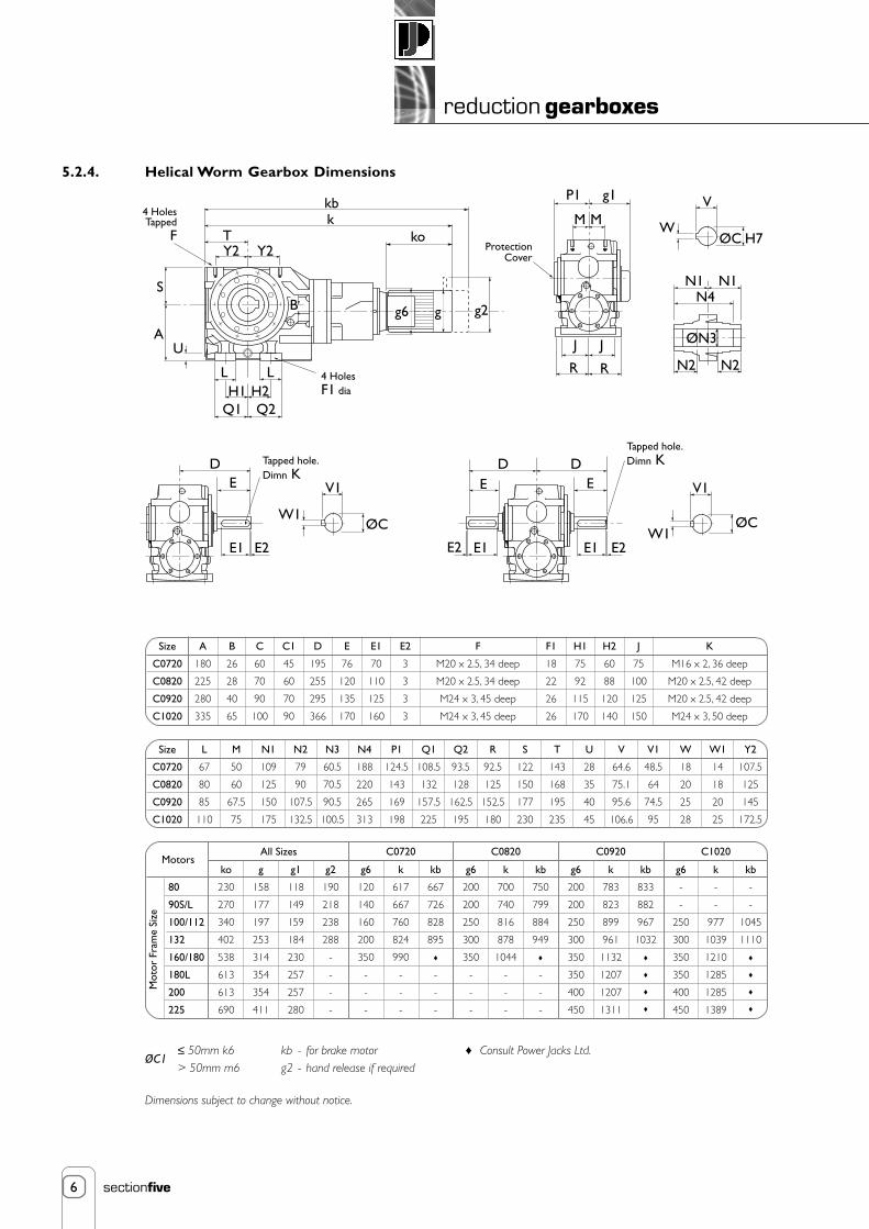
6
reduction gearboxes
sectionfive
kbk
TY2 Y2
ko
S
A
Q2Q1H1 H2
L L
P1 g1
MM
JJ
R R
V
WH7ØC
N1 N1
N2 N2
ØN3
DE
E1 E2
V1
ØCW1
D DEE
E1E1E2 E2W1
V1
ØC
B
U
g6 g g2
4 HolesTapped
F
4 HolesF1 dia
Tapped hole.Dimn K
ProtectionCover
Tapped hole.Dimn K
N4
5.2.4. Helical Worm Gearbox Dimensions
ko
230
270
340
402
538
613
613
690
All SizesMotors
Mot
or F
ram
e Si
ze
C0720
80
90S/L
100/112
132
160/180
180L
200
225
g
158
177
197
253
314
354
354
411
g1
118
149
159
184
230
257
257
280
g2
190
218
238
288
-
-
-
-
g6
120
140
160
200
350
-
-
-
k
617
667
760
824
990
-
-
-
kb
667
726
828
895
-
-
-
C0820
g6
200
200
250
300
350
-
-
-
k
700
740
816
878
1044
-
-
-
kb
750
799
884
949
-
-
-
C0920
g6
200
200
250
300
350
350
400
450
k
783
823
899
961
1132
1207
1207
1311
kb
833
882
967
1032
C1020
g6
-
-
250
300
350
350
400
450
k
-
-
977
1039
1210
1285
1285
1389
kb
-
-
1045
1110
L
67
80
85
110
M
50
60
67.5
75
N1
109
125
150
175
N2
79
90
107.5
132.5
N3
60.5
70.5
90.5
100.5
N4
188
220
265
313
P1
124.5
143
169
198
Q1
108.5
132
157.5
225
Q2
93.5
128
162.5
195
R
92.5
125
152.5
180
S
122
150
177
230
T
143
168
195
235
U
28
35
40
45
V
64.6
75.1
95.6
106.6
V1
48.5
64
74.5
95
W
18
20
25
28
W1
14
18
20
25
Y2
107.5
125
145
172.5
Size
C0720
C0820
C0920
C1020
A
180
225
280
335
B
26
28
40
65
C
60
70
90
100
C1
45
60
70
90
D
195
255
295
366
E
76
120
135
170
E1
70
110
125
160
E2
3
3
3
3
F1
18
22
26
26
H1
75
92
115
170
H2
60
88
120
140
J
75
100
125
150
F
M20 x 2.5, 34 deep
M20 x 2.5, 34 deep
M24 x 3, 45 deep
M24 x 3, 45 deep
K
M16 x 2, 36 deep
M20 x 2.5, 42 deep
M20 x 2.5, 42 deep
M24 x 3, 50 deep
Size
C0720
C0820
C0920
C1020
≤ 50mm k6 kb - for brake motor ♦ Consult Power Jacks Ltd.> 50mm m6 g2 - hand release if required
ØC1
Dimensions subject to change without notice.

7
reduction gearboxes
sectionfive
5.3. In-Line Helical Reduction Gearboxes
5.3.1. Gearbox SelectionCalculate the power capacity required for the gearbox:
P(kW) = Pd (kW) x F
L
Where Pd = Power required to drive the machine and F
L = Load factor (refer to table in Section 5.2.2.)
Select a gearbox type to the closest above the required power (Pd) and to the nearest output speed (hence gear ratio)for the gearbox type.
5.3.2. In-Line Helical Reduction Gearbox Power Rating Guide by Motor Frame Size
5.3.2.1. In-Line Helical Reduction Gearbox Gear RatiosDouble reduction gear ratios only. For single, triple or other reductiond consult Power Jacks.
5.3.2.2. Overview of Motor Power Ratings
4 Pole AC Induction Motors - 3 Phase
6 Pole AC Induction Motors - 3 Phase
MotorFrameSize
63
71
80
90
100
112
132
160
180
200
225
250
280
3.6to9.0
X
X
X
X
-
-
-
-
-
-
-
-
-
11to56
X
X
X
X
-
-
-
-
-
-
-
-
-
3.6to14
-
-
X
X
-
-
-
-
-
-
-
-
-
16to56
X
X
X
X
-
-
-
-
-
-
-
-
-
3.6to14
-
-
X
X
-
-
-
-
-
-
-
-
-
16to56
X
X
X
X
-
-
-
-
-
-
-
-
-
3.6to11
-
-
X
X
X
X
X
-
-
-
-
-
-
12to56
X
X
X
X
X
X
X
-
-
-
-
-
-
3.6to11
-
-
X
X
X
X
X
-
-
-
-
-
-
12to56
X
X
X
X
X
X
X
-
-
-
-
-
-
5.0to12
-
-
X
X
X
X
X
-
-
-
-
-
-
14to63
X
X
X
X
X
X
X
-
-
-
-
-
-
3.6to9.0
-
-
-
-
X
X
X
X
-
-
-
-
-
11to56
-
-
X
X
X
X
X
X
-
-
-
-
-
3.6to14
-
-
-
-
X
X
X
X
-
-
-
-
-
16to56
-
-
X
X
X
X
X
X
-
-
-
-
-
1.4to14
-
-
-
-
-
-
-
X
X
X
X
-
-
16to71
-
-
X
X
X
X
X
X
X
X
X
-
-
1.4to14
-
-
-
-
-
-
-
X
X
X
X
-
-
16to71
-
-
-
-
X
X
X
X
X
X
X
-
-
2.8to14
-
-
-
-
-
-
-
X
X
X
X
X
X
16to45
-
-
-
-
X
X
X
X
X
X
X
X
X
50to71
-
-
-
-
X
X
X
X
X
X
X
-
-
2.8to14
-
-
-
-
-
-
-
X
X
X
X
X
X
16to45
-
-
-
-
X
X
X
X
X
X
X
X
X
50to71
-
-
-
-
X
X
X
X
X
X
X
-
-
UnitSize
M0122 M0222 M0322 M0422 M0522 M0622 M0722 M0822 M0921 M1021 M1321 M1421
RatioRatioRatioRatioRatioRatioRatioRatioRatioRatioRatioRatio
Frame Size
Power (kW)
63
0.12
0.18
71
0.25
0.37
80
0.55
0.75
90
1.1
1.5
100
2.2
3
112
4
132
5.5
7.5
160
11
15
180
18.5
22
200
30
225
37
45
250
55
280
75
90
Frame Size
Power (kW)
63
0.07
0.09
71
0.12
0.18
0.25
80
0.37
0.55
90
0.75
1.1
100
1.5
112
2.2
132
3
4
5.5
160
7.5
11
180
15
200
18.5
22
225
30
250
37
280
45
55

8
reduction gearboxes
sectionfive
5.3.3. In-Line Helical Gearbox Torque RatingsGearbox output torque ratings below are applicable when used with 1450 rpm (4 pole), 960 rpm (6 pole) and 725 rpm (8 pole)motors. Double reduction gear ratios only. For single, triple or other reductions consult Power Jacks.
Note: Power Ratings (kW) = (2*π*M2*Nl)/(i*60*1000).M2 = Maximum output torque rating in Nm.N1 = Motor input power to gearbox in rpm.i = Gear Ratio.GR = Nominal Gear Ratio.
GR
1.4
1.5
2.2
2.5
2.8
3.2
3.5
4
4.5
5
5.6
6.3
7.1
8
9
10
11
12
14
16
18
20
22
28
32
36
45
50
58
63
i
(:1)
3.75
5.066
5.762
6.528
8.348
8.997
11.36
12.88
14.72
16.37
18.05
19.86
23.27
27.92
32.54
36.16
43.54
49.91
56.72
M2
(Nm)
59
68
71
75
79
80
84
87
90
90
90
90
90
90
90
90
84
72
71
M0122
i
(:1)
3.589
5.034
5.547
6.299
8
9.088
11.15
12.37
14.05
15.97
17.58
20.23
21.99
26.4
31.68
35.69
41.49
47.09
53.54
M2
(Nm)
100
116
121
127
136
140
145
148
153
160
160
160
160
160
160
160
160
160
160
M0222
i
(:1)
3.589
5.034
5.547
6.299
8
9.088
11.15
12.37
14.05
15.97
17.58
20.23
21.99
26.4
31.68
35.69
41.49
47.09
53.54
M2
(Nm)
118
135
140
147
161
168
179
186
194
205
208
209
209
209
209
209
199
203
206
M0322
i
(:1)
3.585
5.04
5.649
6.341
8.053
9.129
10.89
12.54
14.58
16.31
17.39
20.61
22
27.3
32.19
35.25
43.2
48.15
54
M2
(Nm)
203
237
249
262
289
299
311
320
329
338
338
338
338
338
338
338
338
338
270
M0422
i
(:1)
3.585
5.04
5.649
6.341
8.053
9.129
10.89
12.54
14.58
16.31
17.39
20.61
22
27.3
32.19
35.25
43.2
48.15
54
M2
(Nm)
292
382
409
413
441
450
450
426
450
450
450
450
450
450
450
450
424
379
270
M0522
i
(:1)
4.438
6.24
6.994
7.851
9.97
11.3
13.48
15.52
18.05
20.2
21.53
25.51
27.24
33.8
39.86
43.64
53.49
59.61
66.86
M2
(Nm)
362
473
510
512
594
604
613
528
596
626
626
626
626
626
626
626
526
470
334
M0622
i
(:1)
3.678
5.094
5.722
6.292
8.218
9.344
11.35
12.48
14.34
16.26
17.94
20.54
23.23
26.93
32.12
35.17
42.21
48.56
53.96
M2
(Nm)
306
425
477
525
655
689
726
740
761
786
794
804
813
825
840
847
863
700
596
M0722
i
(:1)
3.678
5.214
5.792
6.442
8.33
9.352
11.47
12.92
15.04
16.69
18.26
20.66
23.32
28.27
32.97
36.21
44.38
48.46
55.8
M2
(Nm)
483
686
763
849
1100
1220
1310
1340
1410
1420
1360
1460
1540
1580
1620
1650
1690
1690
1540
M0822
i
(:1)
1.479
2.036
2.282
2.562
2.969
3.301
3.688
4.088
4.582
5.073
5.686
6.628
7.404
8.224
9.188
10.27
11.71
M2
(Nm)
574
677
716
756
1150
850
876
1360
1440
1680
1780
1700
1760
2080
2170
1970
2040
M0921
i
(:1)
1.442
2.015
2.191
2.489
2.992
3.242
3.5
4.179
4.545
4.938
5.37
6.724
7.26
7.945
8.578
10.59
11.98
M2
(Nm)
722
1010
1100
1250
1490
1570
1570
2090
2280
2470
2690
3140
3230
3330
3420
3680
3770
M1021
i
(:1)
2.904
3.189
3.638
4.025
4.421
5.042
5.538
6.21
6.879
7.779
8.618
9.891
11.2
M2
(Nm)
1810
1990
2260
2510
2760
3140
3450
3880
4300
4840
5360
6170
5940
M1321
i
(:1)
2.888
3.247
3.822
4.029
4.537
5.333
6.005
6.548
7.27
8.667
9.623
10.07
11.43
M2
(Nm)
2520
2840
3330
3530
3970
4660
5240
5730
6360
7570
8400
8800
9980
M1421

9
reduction gearboxes
sectionfive
"x"
M0122
M0222
M0322
M0422
M0522
M0622
M0722
M0822
M0921
M1021
M1321
M1421
Frame
Øg6
63
209
240
240
63
140
71
213
244
244
71
105
80A
226
257
257
294
304
325
362
442
524
80A
120
80B
226
257
257
294
304
325
362
442
523
80B
120
90S
236
267
267
304
314
335
372
442
523
90S
140
90L
236
267
267
304
314
335
372
442
523
90L
140
90LA
236
267
267
304
314
335
372
442
523
90LA
140
100L
329
339
360
382
442
523
596
717
832
100L
160
112M
329
339
360
382
442
523
596
717
832
112M
160
112MA
329
339
360
382
442
523
596
717
832
112MA
160
132SA
384
442
523
596
717
832
132SA
200
132M
384
442
523
596
717
832
132M
200
132MA
384
442
523
596
717
832
132MA
200
132MB
384
442
523
596
717
832
132MB
200
160M
448
564
631
710
825
160M
350
160L
448
564
631
710
825
160L
350
180M
564
631
710
825
180M
350
180L
564
631
710
825
180L
350
200L
564
631
710
825
200L
400
225S
591
658
710
825
225S
450
225M
591
658
710
825
225M
450
250M
710
825
250M
550
280S
710
825
280S
550
280M
710
825
280M
550
Size
M0122
M0222
M0322
M0422
M0522
M0622
M0722
M0822
M0921
M1021
M1321
M1421
a
110
130
130
165
165
195
205
260
310
370
410
500
b
110
110
110
135
135
150
170
215
250
290
340
380
c
12
16
16
20
20
24
25
35
40
45
50
50
e
131
152
152
200
200
235
245
310
365
440
490
590
f
135
145
145
190
190
210
230
290
340
400
450
530
h
75
90
90
115
115
130
140
180
225
250
265
300
h1
-
-
-
-
-
14.5
-
-
-
-
-
-
i
58
75
75
90
100
100
115
140
160
185
220
260
n
25
35
35
55
55
60
60
75
90
110
110
150
o
152
170
170
204
204
220
252
320
372
428
470
546
o1
76
84
84
97
97
110
119
167
200
225
242
278
p
-
-
-
-
-
246
295
360
433
505
563
630
p3
149
180
180
208
208
214
250
310
394
446
483
551
Øs
10
10
10
15
15
15
19
19
23
27
34
41
Ød
20 k6
25 k6
25 k6
30 k6
35 k6
35 k6
40 k6
50 k6
60 m6
70 m6
90 m6
100 m6
L
40
50
50
60
70
70
80
100
120
140
170
210
L11
4
4
4
4
7
7
5
10
10
15
15
15
L12
32
40
40
50
60
60
70
80
100
110
140
180
t
22.5
28
28
33
38
38
43
53.5
64
74.5
95
106
u
6
8
8
8
10
10
12
14
18
20
25
28
w
M6 x 1 x 16 deep
M10 x 1.5 x 22 deep
M10 x 1.5 x 22 deep
M10 x 1.5 x 22 deep
M12 x 1.75 x 28 deep
M12 x 1.75 x 28 deep
M16 x 2.0 x 36 deep
M16 x 2.0 x 36 deep
M20 x 2.5 x 42 deep
M20 x 2.5 x 42 deep
M24 x 3.0 x 50 deep
M24 x 3.0 x 50 deep
5.3.4. In-Line Helical Gearbox Dimensions - Foot Mounted
Note: All dimensions in millimeters.Dimensions subject to change without notice.All parallel keys are to DIN 6885.
u
t
h
cn
fb
s
oo1Refer Section 7
“x”
L
L12L11
dp3ph1
g6
ae
iTapped
Hole w
Low Speed Shaft

10
reduction gearboxes
sectionfive
Note: All dimensions in millimeters.Dimensions subject to change without notice.All parallel keys are to DIN 6885.
Øb1
Ød
Øa1
L11 L12L
f1c1
i2
pp3
p5
h1
g6
Refer Section 7
g g2
u
tLow Speed Shaft
Note: Sizes 01 to 08 are also available as C - Flange (B14) Mounting, please consult Power Jacks for details.
Sizes1, 2, 3, 4, 5,6, 7 and 8
Sizes9, 10, 13and 14
4 x Øs 8 x Øs
Øe1Øe1
"x"M0122M0222M0322M0422M0522M0622M0722M0822M0921M1021M1321M1421
FrameØg6
63209240240
63140
71213244244
71105
80A226257257294304325362442523
80A120
80B226257257294304325362442523
80B120
90S236267267304314335372442523
90S140
90L236267267304314335372442523
90L140
90LA236267267304314335372442523
90LA140
100L
329339360382442523596717832
100L160
112M
329339360382442523596717832
112M160
Motor Frame Size
112MA
329339360382442523596717832
112MA160
132M
384442523596717832
132M200
132MA
384442523596717832
132MA200
132MB
384442523596717832
132MB200
160M
448564631710825
160M350
160L
448564631710825
160L350
180M
564631710825
180M350
180L
564631710825
180L350
200L
564631710825
200L400
225S
591658710825
225S450
225M
591658710825
225M450
250M
710825
250M550
280S
710825
280S550
280M
710825
280M550
SizeM0122
M0222
M0322
M0422
M0522
M0622
M0722
M0822
M0921M1021M1321M1421
øa1120140160200120140160200120140160200140160200250140160200250200250300200250300300350450450550550
øb18095110130809511013080951101309511013018095110130180130180230130180230230250350350450450
c199101010101010101010101111111111111111111111111111171718222525
øe1100115130165100115130165100115130165115130165215115130165215165215265165215265265300400400500500
f133
3.53.533
3.53.533
3.53.53
3.53.543
3.53.54444
3.544455555
h1--------------------
14.514.514.5
---------
i24040404050505050505050506060606070707070707070808080100100140140170210
p--------------------
116116116155155155180180198245288320
p37474747490909090909090909393939393939393848484110110110130130
----
p5767676769191919191919191115115115115115115115115130130130140140140182182230260278318
Ød20 k620 k620 k620 k625 k625 k625 k625 k625 k625 k625 k625 k630 k630 k630 k630 k635 k635 k635 k635 k635 k635 k635 k640 k640 k640 k650 k650 k660 m670 m690 m6100 m6
Øs999116.699116.699119911
13.59911
13.511
13.513.511
13.513.513.517.518181818
L4040404050505050505050506060606070707070707070808080100100120140170210
L1144444444444444447777777555101010151515
L1232323232404040404040404050505050606060606060607070708080100110140180
t22.522.522.522.528282828282828283333333338383838383838434343
53.553.564
74.595106
u666688888888888810101010101010121212141418202528
wM6 x 1 x 16 deepM6 x 1 x 16 deepM6 x 1 x 16 deepM6 x 1 x 16 deep
M10 x 1.5 x 22 deepM10 x 1.5 x 22 deepM10 x 1.5 x 22 deepM10 x 1.5 x 22 deepM10 x 1.5 x 22 deepM10 x 1.5 x 22 deepM10 x 1.5 x 22 deepM10 x 1.5 x 22 deepM10 x 1.5 x 22 deepM10 x 1.5 x 22 deepM10 x 1.5 x 22 deepM10 x 1.5 x 22 deepM12 x 1.75 x 28 deepM12 x 1.75 x 28 deepM12 x 1.75 x 28 deepM12 x 1.75 x 28 deepM12 x 1.75 x 28 deepM12 x 1.75 x 28 deepM12 x 1.75 x 28 deepM16 x 2.0 x 36 deepM16 x 2.0 x 36 deepM16 x 2.0 x 36 deepM16 x 2.0 x 36 deepM16 x 2.0 x 36 deepM20 x 2.5 42 deepM20 x 2.5 42 deepM24 x 3.0 50 deepM24 x 3.0 50 deep
5.3.5. In-Line Helical Gearbox Dimensions - Flange Mounted
“x”
TappedHole w

6. couplings and drive shafts
15 Models, Curved Jaw DesignReliable, rugged and compactNo need for lubricationGrease and oil resistantBores sizes up to 110 mmTorque ratings: up to 3300 Nm
Section 6.1.1. - Flexible JAW Coupling
7 Model sizesCompact, light and robust2 Metal Hubs and flexible elementEasy to install and maintainBores sizes up to 80 mmTorque ratings: up to 2000 Nm
Section 6.1.2. - Flexible Spacer Coupling
Flanged or Continuous Sleeve ModelsFlex-Flex and Flex-Rigid configurationsStrong, rugged Steel CouplingsHigh transmittable torque and high maximum speedBores sizes up to 130 mmTorque ratings: up to 20700 Nm
Section 6.1.3. - Steel Flexible GearCouplings
Drive Shafts
Standard Drive Shafts with Machine Journals and KeywaysDrive Shaft ends can be machined to customer design3 Standard sizes with others on request
Plummer Blocks
Rugged, strong, cast iron Plummer BlocksFloating or Locating BearingsOne Piece and Split Housing Designs
Hand Wheels
Rugged, lightweight Hand WheelsSuitable for manual operation of Gearboxes or Screw Jacks
Section 6.2.1. - Drive ShaftsSection 6.2.2. - Plummer BlocksSection 6.2.3. - Hand Wheels
POWER JACKSGroupmanufacturers of precision screw jacks, actuators and gearboxes

1
couplingsanddriveshafts
sectionsix
Contents
6.1. Jaw and Geared Flexible Couplings 2
6.1.1. Flexible Jaw Couplings 3
6.1.2. Flexible Spacer Couplings 4
6.1.3. Steel Flexible Gear Couplings 5
6.2. Drive Shafts and Plummer Blocks 7
6.2.1. Drive Shafts 7
6.2.2. Plummer Blocks 9
6.2.3. Hand Wheels 10

2
couplingsanddriveshafts
sectionsix
6.1. Jaw and Geared Flexible Couplings
Selection of Coupling Type
The selection of coupling type depends on the installation and the type of misalignment. The three main types of misalignmentencountered are:-
1. Angular Misalignment is usually present to some extent on all applications, typical values 1° - 2°. Sometimes highervalues are necessary.
2. Parallel (Radial) Misalignment is also nearly always present. A well aligned installation might have values below0.25 mm.
3. Axial Misalignment (End Float) sometimes caused by thermal expansion or as a result of machine design.
Other considerations include:• Backlash Free Couplings are either one part couplings or have bolted joints. These are effective for precise
positioning and to avoid wear on reversing drives.
• Torsional rigidity of couplings depends on the joining method. Types with rubber or plastic elements can beconsidered as torsionally soft and will have an amount of twist at rated torque.
Procedure:1. Decide if the coupling should be torsionally soft or rigid.
2. Consider whether a small amount of backlash is acceptable.
3. Calculate the required coupling torque.
4. Make a provisional selection.
5. Check that the coupling’s maximum speed is sufficient.
6. Check that the coupling’s dimensions are acceptable.
7. Contact Power Jacks with your order or technical enquiry
Selection of Coupling Size
where S = Service Factor - dependant on drive conditions (refer to each coupling)
Select the coupling which is rated above the calculated torque. If a brake is present in the system the coupling should be based oneither the brake torque or the transmitted torque whichever is greater.
General Notes1. Maximum misalignment values are extremes and should not be combined. As operating misalignment approaches
the maximum, torque and power ratings should be reduced to maintain life.
2. Gear couplings accommodate parallel misalignment by converting it to angular misalignment at the gear meshes inthe flexible halves of the coupling.
3. The maximum axial misalignment values apply when the coupling is aligned. If axial misalignment greater than thelisted maximum is required, consult Power Jacks.
4. The inertia values includes shafts through the bores.
5. When ordering please quote the coupling size and type, specify the bore and keyway sizes, and advise if pullerholes or set-screws are required.
6. For maximum performance, the actuators, shafts, gear boxes and motor should be carefully aligned.
7. Imperial couplings on request..
9550 * Power Transmitted (kW) * S
RPMCoupling Torque, T(Nm) =
KeywaysStandard Bores
Standard Keyways
MetricB.S. 4500 1969 H7
B.S. 4235 Part 1 1967 P9
ImperialB.S. 1916 Part 1 1953 K7
B.S. 46 Part 1 1958

3
couplingsanddriveshafts
sectionsix
Type
Aluminimum Hub Couplings19/2424/3028/3838/45Cast Iron Hub Couplings19/2424/3028/3838/4542/5548/6055/7065/7575/9090/100100/110
Hub 'A' Hub 'B' Dimensions (mm)Pre
Bore
66912
-----------
MinBore
681014
---
141619222530--
MaxBore
19242838
---
384248556575--
PreBore
18222636
------
536373--
MinBore
20253040
68104045506070804545
MaxBore
24303845
243238455560707590100110
A
40556580
4055658095105120135160200225
C
31394664
---
66758598115135
--
C1
38486175
4055657893103118133158170180
L
667890114
667890114126140160185210245270
L2
25303545
253035455056657585100110
E
16182024
1618202426283035404550
s
22
2.53
22
2.533
3.54
4.55
5.56
b
12141518
1214151820212226303438
G
20242838
---
3740455261698189
F
18273038
182730384651606880100113
g
M5M5M6M6
M5M5M6M8M8M8M10M10M10M10M12
h
10101515
1010151520202020252530
kg
0.110.240.420.86
0.340.91.52.353.554.857.410.817.729.639
L1 & Weight
6.1.1. Jaw Type Flexible Coupling
• Curved jaw design.
• No need for lubrication.
• Quick and simple to install.
• Reliable, rugged and compact.
• Smooth, silent action.
L
Service Factor S = Ft * Fz * Fs
Note All couplings use 92 Shore elastomeric element (white) as standard. 80, 98 and 95 available on request.Maximum torque must not be exceeded during start-up operation.More accurate alignment will increase coupling life and reduce vibration. Dimensions “E” and “L” mustbe observed.P = Consult Power Jacks for more details.
G G
ØA
ØC
ød
L1 L2
s
Temperature (oC)
Temperature Factor (Ft)
-30oC to +30oC
1
40oC
1.2
60oC
1.4
80oC
1.8Starts/Day
Starting Factor (Fz)
0 to 10
1
101 to 200
1.2
201 to 400
1.4
401 to 800
1.8
Shock Type
Shock Factor (Fs)
None
1
Light
1.5
Medium
1.8
High
2.5
Note Weight of min. bored coupling with standard A/B hub combination.All couplings metric bored and keyed as standard. Consult Power Jacks for standard bore sizes and specials.
• High power transmission density.
• 4 Standard spider types available.
• Elastomeric element resistant to heat(-40°→+90°c), grease, oil and chemicalagents.
• Hubs in aluminium and sintered iron.
Torque (Nm)
MisalignmentValues
Speed
14PPPPPPP
19/2410202.61.20.90.2
14000
24/3035709
1.40.90.22
10600
28/3895190251.50.90.258500
38/45190380491.81
0.287100
42/552655306921
0.326000
48/60310620812.11.10.365600
55/70375750932.21.10.384750
65/754258501112.61.20.424250
75/9097519502543
1.20.483550
90/100240048006243.41.20.5
2800
100/110330066008583.81.20.522500
Nominal, Tkn
Max Tkmax
Vibrating Tkw (10Hz)Axial (mm)Angular (deg)Radial (mm)Max (rpm)
Size
gh
Eb
s
A A
L
G G
ØA
ØC ød
L1 L2
sgh
Eb
s
A B
G G
ØA
ØC
ød
L1 L2
sgh
Eb
s
B B
ød1
ød1

4
couplingsanddriveshafts
sectionsix
6.1.2. Flexible Spacer Couplings
• Compact, light, robust, safe in operation, long service life.• Two identical hubs and one flexible element.• Hubs of high tensile steel.• Large permissible bores, various hub lengths.• Driving dogs have smooth surface, high durability.• Generously proportioned compression-stressed flexible inserts.• Damps vibrations and shocks, compensates for axial, radial and angular misalignment.
Elastomeric Element features:
• Inserts made of “90 Shore A” Polyurethane (G) as standard or tough “55 Shore D” Hytrel (H).• Operating temperature range: -40°C → +80°C as standard• Elastomeric element is resistant to oil and grease.
Coupling Performance
Note All dimensions in mm. *Insert length L here in millimetres.
Note The best possible alignment will result in the best coupling performance.
Service Factor
The service factor must be chosen according to working conditions between 1 (light duty) and 3 (arduous duty).
Critical Speed & Spacer length
Spacer coupling lengths can be provided up to a maximum of 6m depending on rotational speed. For advice on thecritical speed of a given coupling consult Power Jacks.
Misalignment
Coupling Dimensions
TypeSize
727698120138165185
B-G B-H-GNominalTorque
TKN (Nm)32631252504006001000
MaximumTorque
TKmax (Nm)6412525050080012002000
TorsionalAngle (deg)
at TKN4444444
NominalTorque
TKN (Nm)45901753505608501400
MaximumTorque
TKmax (Nm)8012528056090017002800
TorsionalAngle (deg)
at TKN2,52,52,52,52,52,52,5
Max SpeedNmax (rpm)Elastomeric
Element10000900075006000500040003600
Size727698120138165185
d min (d1, d2)9121215152030
d max (d1, d2)30303848556580
d3727698120138165185
E14162428303645
L128304250556580
N5050617186100115
R4545607085100115
S +/- 166666810
ModelCF - B - (H) - 72 - G - L = *CF - B - (H) - 76 - G - L = *CF - B - (H) - 98 - G - L = *CF - B - (H) - 120 - G - L = *CF - B - (H) - 138 - G - L = *CF - B - (H) - 165 - G - L = *CF - B - (H) - 185 - G - L = *
Element TypeB - StandardH - Hytrel
Radial (mm)0.50.25
Axial (mm)+/- 1+/- 1
Angular (deg)1
0.5
N d1
L1 L L1
S±1
E
d2 d3R

5
couplingsanddriveshafts
sectionsix
6.1.3.1. Continuous Sleeve Steel Gear Coupling
• Vari-crown tooth form for improved torque transmission and longer life.
• Strong compact design.
• High transmittable torque ratings.
• Low inertia and high maximum speeds.
• Steel reinforced high misalignment seals.
• Spacer couplings available on request.
6.1.3. Steel Flexible Gear Couplings
Note *Balanced speed approximately 3 times higher.Draw off holes are optional, consult Power Jacks.All dimensions in millimetres.
Note 1. All dimensions in millimetres.
2. Dimension ‘R ‘and ‘CAC’ are the clearance required to align the coupling when installing.
3. These couplings are designed for grease lubrication. A list of suggested lubricants and quantities is detailed in theinstallation manual supplied with each full coupling.
4. Where a coupling is exposed to sustained temperatures above 100ºC (212ºF) a coupling with high temperatureseals must be used, consult Power Jacks Ltd.
Full-Flex Gear Coupling
Two flexible hubs and sleeve assembly.Accommodates angular, parallel and axial misalignments.
Flex-Rigid Gear Coupling
Flexible and rigid hub assembly. The flexible hub isstandard and the rigid hub is splined into the sleeve.Accommodates angular and axial misalignment only.
Coupling Size and Type
Rated Torque (Nm)Rated Power (kW/100 rpm)Maximum Speed Unbalanced * (rpm)FullFlex
FlexRigidInertiaWeight (Rough Bore)Maximum
Rough BoreDDHDHLGG1OALRLSDCCBDSL
CFF022CFR022
2853
60000.131o
0.30.5o
0.30.0022.331
8 x71184513831080955134925
CFF038CFR038
8548.9
50000.181o
0.30.5o
0.30.0043.642
12 x 815956046313951176455732
CFF050CFR050
227823.842000.181o
0.30.5o
0.30.0105.956
16 x 101812183523131081246557633
CFF065CFR065
341735.837500.251o
0.60.5o
0.60.0229.170
20 x 1222140100576191211457869539
CFF075CFR075
569559.630000.301o
0.60.5o
0.60.053
1584
22 x 143016812167619140175956
12148
CFF090CFR090
9967104.428000.301o
0.60.5o
0.60.112
2997
28 x 16321911371086192222351026
14051
CFF100CFR1001423814924000.181o
0.60.5o
0.60.225
41111
28 x 16442221591116192292411186
16559
CFF115CFR11520787217.722000.18
10.60.50.6
0.37657130
32 x 18602411841276192602641246
18462
Full-FlexFlex-Rigid
ParallelAngularAxial (+/-)AngularAxial (+/-)(kg m2)(kg)
(b x h)
MaximumMisalignment
MaximumMisalignment
BoreKeyway
ROALLS
SL
CBDHD OD
G1
DCDraw off holes
G
HL
OALLS
SL
CBDHDOD
G1
DCDraw off holes
G
HL
R
Nature of Load on Unit
Service Factor, S
Uniform
1.0
Light Shock
1.25
Medium Shock
1.50
Heavy Shock
2.0
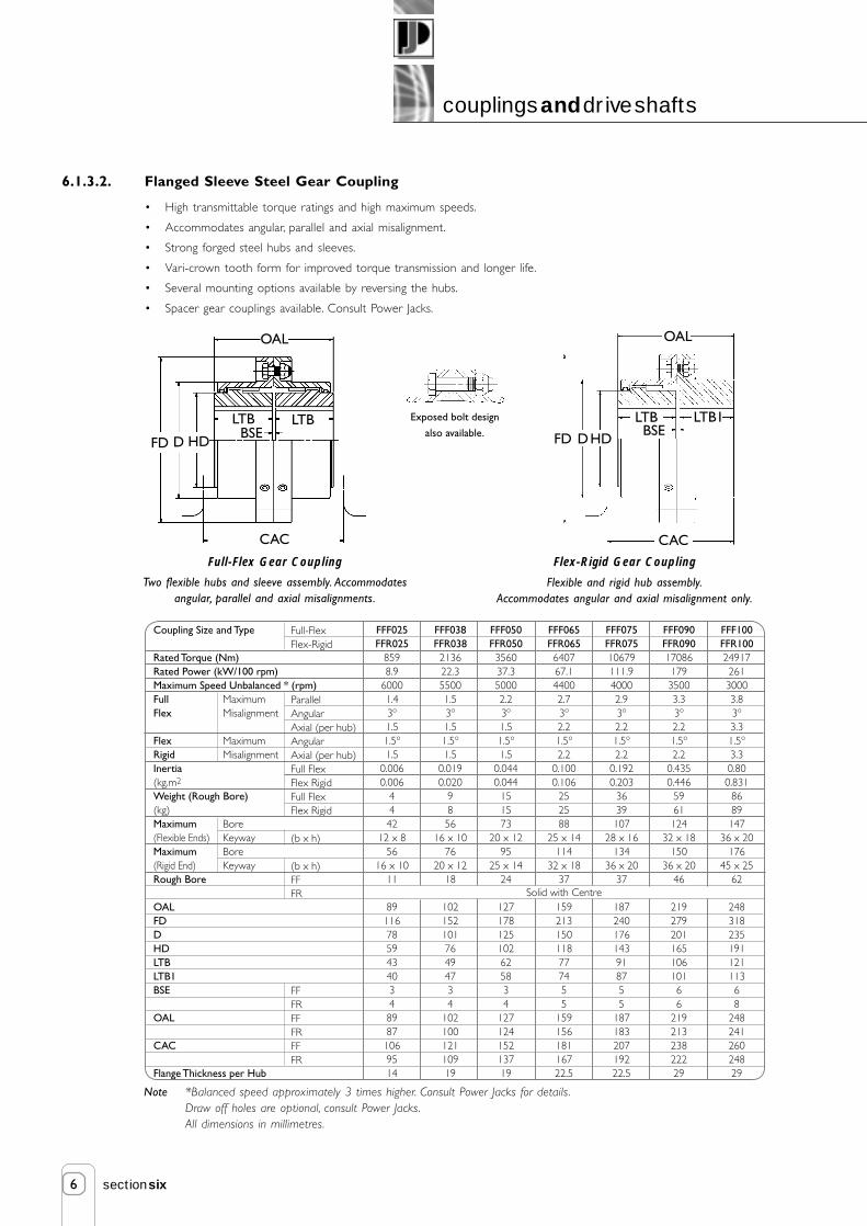
6
couplingsanddriveshafts
sectionsix
Exposed bolt design
also available.
6.1.3.2. Flanged Sleeve Steel Gear Coupling
Full-Flex Gear Coupling
Two flexible hubs and sleeve assembly. Accommodatesangular, parallel and axial misalignments.
Flex-Rigid Gear Coupling
Flexible and rigid hub assembly.Accommodates angular and axial misalignment only.
FD
• High transmittable torque ratings and high maximum speeds.
• Accommodates angular, parallel and axial misalignment.
• Strong forged steel hubs and sleeves.
• Vari-crown tooth form for improved torque transmission and longer life.
• Several mounting options available by reversing the hubs.
• Spacer gear couplings available. Consult Power Jacks.
Note *Balanced speed approximately 3 times higher. Consult Power Jacks for details.Draw off holes are optional, consult Power Jacks.All dimensions in millimetres.
Coupling Size and Type
Rated Torque (Nm)Rated Power (kW/100 rpm)Maximum Speed Unbalanced * (rpm)FullFlex
FlexRigidInertia(kg.m2
Weight (Rough Bore)(kg)Maximum(Flexible Ends)Maximum(Rigid End)Rough Bore
OALFDDHDLTBLTB1BSE
OAL
CAC
Flange Thickness per Hub
FFF025FFR025
8598.9
60001.43o
1.51.5o
1.50.0060.006
4442
12 x 856
16 x 1011
89116785943403489871069514
FFF038FFR038213622.355001.53o
1.51.5o
1.50.0190.020
9856
16 x 1076
20 x 1218
10215210176494734
10210012110919
Solid with Centre
FFF050FFR050356037.350002.23o
1.51.5o
1.50.0440.044
151573
20 x 1295
25 x 1424
127178125102625834
12712415213719
FFF065FFR065640767.144002.73o
2.21.5o
2.20.1000.106
252588
25 x 14114
32 x 1837
159213150118777455
15915618116722.5
FFF075FFR07510679111.940002.93o
2.21.5o
2.20.1920.203
3639107
28 x 16134
36 x 2037
187240176143918755
18718320719222.5
FFF090FFR0901708617935003.33o
2.21.5o
2.20.4350.446
5961124
32 x 18150
36 x 2046
21927920116510610166
21921323822229
FFF100FFR1002491726130003.83o
3.31.5o
3.30.800.831
8689147
36 x 20176
45 x 2562
24831823519112111368
24824126024829
Full-FlexFlex-Rigid
ParallelAngularAxial (per hub)AngularAxial (per hub)Full FlexFlex RigidFull FlexFlex Rigid
(b x h)
(b x h)FFFR
FFFRFFFRFFFR
MaximumMisalignment
MaximumMisalignment
BoreKeywayBoreKeyway
D HD
LTB LTB
OAL
BSE
CAC
OAL
LTB1
CAC
FD DHD
LTBBSE

7
couplingsanddriveshafts
sectionsix
6.2. Drive Shafts and Plummer Blocks
6.2.1. Selection Guidelines
1. Select Drive Shaft Diameter
Select a standard drive shaft from the drive shaft table (refer 6.2.1.1.) and check its torque rating and angle of twistrating against the application requirements.
if Transmitted Torque (Nm) < Maximum Drive Shaft Torque (Nm)
&
if Acceptable Angle of Twist (Deg.) for shaft length < Rated Angle of Twist for Drive Shaft (Deg.)then drive shaft diameter selected is acceptable.
2. Check Drive Shaft Critical Speed
For the unsupported shaft length calculate the drive shaft critical speed for the support conditions required(refer 6.2.1.2.).
If Shaft Speed (rpm) < Drive Shaft Critical Speed (rpm)then drive shaft selection and configuration is acceptable.
2(a). Plummer Block Selection
If the drive shaft fails due to the critical speed reduce the unsupported drive shaft length using plummer blocks.
e.g. one plummer block at each end of the drive shaft and one in the middle, reducing the unsupported length to halfthe total drive shaft length.
Select a plummer block from the table relating to the appropriate shaft diameter size (refer 6.2.2.).
Re-calculate the critical speed for the new unsupported length and check for acceptability.
If space constraints restrict the number of plummer blocks and the drive shaft fails on the critical speed try increasingthe shaft diameter to the next size up or consult Power Jacks for detailed analysis.
6.2.1.1. Standard Drive Shafts
There are three standard drive shaft sizes offered by Power Jacks with ends machined to suit actuator system couplingshowever drive shafts can be supplied to customer sizes with specific end designs
Standard Drive Shafts
20mm Diameter
30mm Diameter
40mm Diameter
Rated Torque (Nm)
85
285
675
Rated Angle of Twist per Metre (Degrees)
4
2.6
2
Note 1. For other shaft and plummer block sizes and styles consult Power Jacks Ltd.
2. For detailed shaft analysis and selection consult Power Jacks Ltd.
Note 1. For other drive shaft types and sizes consult Power Jacks Ltd.
2. For detailed analysis consult Power Jacks Ltd.
3. Dimensions subject to change without notice.

8
couplingsanddriveshafts
sectionsix
If Shaft Speed (rpm) < Drive Shaft Critical Speed (rpm) then drive shaft selection and configuration is acceptable.
Allowable Drive Shaft Speed (rpm) =
L L
Supported Both Ends, Fdcs = 1 Fixed / Supported Fdcs = 1.6
Critical Speed (rpm) for
Unsupported Length "L" (from chart below) x Fdcs
6.2.1.2. Drive Shaft Critical Speed
Drive Shaft Critical Speed Factors, Fdcs
10,000
1000
100
101 10
Allo
wab
le S
peed
(R
PM)
Unsupported Shaft Length (m)
Based on simply supported both ends and 70% of the critical speed.(The factor of safety allows for couplings and slight misalignment)
20mm Diameter 30 mm Diameter 40 mm Diameter
LEGEND
DRIVE SHAFT CRITICAL SPEED GRAPH(Shaft Whirling)

9
couplingsanddriveshafts
sectionsix
6.2.2. Plummer Blocks
6.2.2.1. One Piece Housing Plummer Block
Note:- 1. All dimensions in mm.
2. For other styles and sizes of Plummer Blocks consult Power Jacks Ltd.
3. Dimensions are subject to change without notice.
ModelPB20PB30PB40
ØD203040
A165185205
B465260
C678082
E192225
F405060
H7292109
L130150170
MM12M12M12
N202020
P151515
Weight (kg)1.42
2.9
Notes 1. All dimensions in mm.
2. Bore diameter tolerances: (H6+H7)/2.
3. Material: Cast Iron housing with eccentric locking ring.
4. Dimensions are subject to change without notice.
5. For other styles and sizes of Plummer Blocks consult Power Jacks Ltd.
6.2.2.2. Split Housing Plummer Block
Plummer blocks are to DIN736 with anti-friction bearings with tapered bores and adapter sleeve. The housings are made of cast ironand are sealed with felt strips on both sides. The housings are designed to allow floating or located bearings (bearing position set withone or two locating rings).
It is recommended when arranging drive systems only one plummer block with located bearing is used in one drive line, to avoiddistortion of the drive.
Floating Bearing
Located Bearing
EF
M
B
P
NC
H
AL
ØH LE
K
DBA
F
C
J
ØG bolt hole
Model A B C D E F G H J K L Weight(kg)
PB1-20 96 127 20.5 32 34 14 10 20 33.33 65 10.5 0.6
PB1-30 121 152 23.5 40 39.2 17 12 30 42.9 82.5 12.5 1.1
PB1-40 136 175 24.5 48 47.7 19 12 40 49.2 99 15 1.9
PB1-50 159 203 26 54 49.7 22 16 50 57.2 115 17 2.8
PB1-60 186 240 29.5 60 60.5 26.5 16 60 69.9 138 21 4.5
ØD

10
couplingsanddriveshafts
sectionsix
6.2.3. Hand Wheels
Notes: 1. Material: Polished aluminium casting and rotating handle.2. Bored and keyed to BS4235 Part 1.
3. All dimensions in millimetres unless otherwise stated.
4. Dimensions subject to change without notice.
5. Other types of hand wheels are available on request. Consult Power Jacks.
B
A
ØD
ØE
C
Model
HW 005
HW 010
HW 025
HW 050
HW 100
A
40
50
56
56
66
B
14
22
24
24
30
C
36
38
43
43
44
D
98
157
198
198
247
E
24
32
40
40
49
H7 Bore
10
14
16
19
25

POWER JACKSGroupmanufacturers of precision screw jacks, actuators and gearboxes
Other Motors
Power Jacks can supply Electric Motors for all applications whether AC or DC Motors including:
3-Phase AC with or without brake to EFF 1 or EFF 2
1-Phase AC capacitor start/induction run or capacitor start/capacitor run
1-Phase AC with brake
DC Permanent Magnet Motors (with or without brake)
DC Servo Motors (with or without brake and feedback devices)
Marine Motors
Hazardous Area Motors (including ATEX)
Aluminium, cast iron or steel housings
NEMA and Japanese standard Motors
Integral AC Inverter (option of local controls)
Tropicalised Motors
7. electric motors
2, 4, 6 or 8 Pole
220 ➔ 240 VAC / 380 ➔ 415 VAC ➔ 3 Phase
50/60 Hz
Foot (B3), Flange (B5) or Face (B14) mounting
IEC Frames 63 ➔ 200 as standard
Enclosure IP54 ➔ 55 or higher
DC or AC Type Brakes
Encoder options
Forced ventilation
Power ratings up to 30 kW as standard

1
electric motors
sectionseven
Contents
7.1. Electric Motors 27.1.1. AC Motors 2
7.1.2. AC Motor Performance - 1500 rpm (4 pole) 2
7.1.3. AC Motor Performance - 1000 rpm (6 pole) 3
7.1.4. AC Motors with Integral Encoders 3
7.1.5. AC Motors with Forced Ventilation 3
7.1.6. Motor Dimensions 4
7.1.7. AC Motors with Brakes 6

2
electric motors
sectionseven
7.1. Electric Motors
Power Jacks can supply electric motors for all applications whether AC or DC motors are required.Detailed in this section of the Design Guide are some of the most popular motors used in industrialapplications.
STR = Starting Torque Ratio SCR = Starting Current Ratio PUT = Pull Up Torque Ratio
POT = Pull Out Torque Ratio V = Air Velocity J = Rotor Interia WK2
7.1.1. AC Motors
Standard Specification
• 3 Phase, 50 Hz / 60Hz.
• 220-240/380-415V up to 3kW.
• 380-415/660-720V 4 kW & above.
• B3 Foot, B5 Flange and B14 Face Mounting.
(or a combination).
• 4 Pole (1500 rpm).
• 6 Pole (1000rpm).
• IEC Frame Sizes 63 → 200.
• Enclosure IP55, TEFV.
• S1 Continuous rating.
Optional
• Brake motors - AC or DC units.
• 2 and 8 Pole 3 phase AC motors.
• Single phase AC motors.
• DC motors - permanent magnet or servo.
• Cast Iron or Steel construction motors.
• High altitude and high temperature options.
• Integral AC inverter.
• Integral encoder and/or Forced ventilation.
• Enclosures IP56 → IP68.
• Tropicalised motors.
• NEMA and Japanese standard units.
• Marine motors.
• Explosion proof motors.
Features
• High efficiency -low running costs.
• Low noise levels.
• High power factors.
• High torque with smooth acceleration and lowcurrent.
• Multi-mount versatility for mounting arrangementand teminal box position.
• Aluminium construction for light weight andcorrosion resistance.
• Four position cable entry.
7.1.2. AC Motor Performance Data - 1500 rpm (4 Pole)
0.120.180.250.370.550.751.11.52.234
5.57.51115
18.52230
kW
FullLoadSpeed(rpm)
FullLoad
Torque
Direct on Line Star DeltaY
AirVel.
RotorInertia
NoiseLevel
FrameSize
FLCIN
(Amps)
Power
0.1660.250.330.50.751.01.52.03.04.05.57.5101520253040
0.500.670.841.171.661.972.763.75.06.78.711.615.422.029.437.043.058.0
0.470.640.801.111.581.882.633.54.86.48.311.014.720.928.035.041.055.0
0.470.640.81.111.581.882.633.54.86.48.311.014.720.928.035.041.053.0
59.062.069.071.075.078.079.581.083.584.586.588.089.091.592.092.593.092.5
52.058.068.069.075.079.080.082.083.585.587.088.589.591.592.592.593.092.5
42.051.062.063.070.077.078.080.083.085.086.088.089.090.591.591.592.091.7
0.620.660.650.680.670.740.760.770.800.800.800.820.830.830.840.820.840.85
0.530.560.550.570.570.650.660.680.740.740.740.760.770.780.790.760.800.82
0.400.440.440.450.450.500.520.550.610.610.600.640.650.670.680.640.690.73
5555
7.57.5991010111212
12.512.513.513.514.5
----------
0.650.600.600.500.500.650.600.50
----------
2.22.22.22.32.32.62.22.1
----------
0.750.700.700.650.650.800.750.75
0.851.251.712.53.75.17.510.114.820.226.536.249.471.597.5120143196
1.92.21.81.82.01.82.22.52.22.32.52.42.52.52.52.82.52.8
2.753.14.04.04.24.45.15.65.55.87.07.57.57.77.78.47.56.7
2.02.22.22.22.42.22.52.82.52.52.92.92.92.92.93.22.92.6
1.652.01.61.61.81.62.02.21.92.12.12.12.12.02.02.22.02.25
393949494949525255555659596363666665
136013701400141014101410141014201415141514401450145014701470147014701465
63S63S71S71S80M80M90S90L100L100L112M132S132M160M160L180M180L200L
0.00050.000630.000840.000870.00150.00190.00280.00350.0080.0090.0150.0270.0290.0680.0840.170.190.40
Efficiency
(%)
Power FactorCosØ
PN
hp 380V
400V
415V
1.0 0.75 0.5 1.0 0.75 0.5 Vm/s
LPAdB(A)
Jkgm2
STR SCR POT PUT STR SCR PUTMNNm
MAMN
n min-1 IAIN
MKMN
MSMN
MAMN
IAIN
MSMN

3
electric motors
sectionseven
7.1.3. AC Motor Performance Data - 1000 rpm (6 Pole)
Power Jacks can supply electric motors for all applications whether AC or DC motors are required. Detailed in this section of theDesign Guide are some of the most popular motors used in industrial applications.
7.1.4. AC Motors with Integral Encoder
Standard AC motors are available with hollow shaft incremental encoder suitable for most advanced inverters to give aclosed loop control or as a speed or position feedback indicator.
• Flexible hollow shaft design.• Maximum speed = 6000 rpm.• Protection class IP64, IP65 on request.• Overall motor enclosure rating IP55 as standard.• Operating temperature: -10oC → +70OC.• Standard output signal: 5 VDC, RS422, quadrature, marker and
compliments (A, B, N, A, B, N)• Current consumption: 40 mA @ 5 VDC.• Number of pulses per revolution: 0 → 8192• Other encoder types are available on request including: 10 → 30VDC RS422 and push-pull, absolute
encoders.
7.1.5. AC Motors with Forced Ventilation
The use of a specially designed, forced cooled motor, with a separately driven constant speed fan can overcome the de-rating problems associated with inverter drives. The fan units operate on a 50 Hz supply as follows;-
Frame size 63 → 80 = Single phase, 220/240 VAC Frame size 90 → 180 = Three phase 230/400 VAC
Note 1. L1 = Motor with encoder and force vent unit.
2. L2 = Motor with brake, encoder and force vent unit.
3. Terminal box dimensions for force vent units are 103 x103 mm.
STR = Starting Torque Ratio SCR = Starting Current Ratio PUT = Pull Up Torque Ratio
POT = Pull Out Torque Ratio V = Air Velocity J = Rotor Interia WK2
L1
L2
309
365
Frame Size 63
332
387
71
384
434
80
456
510
90
487
560
100
487
561
112
562
656
132
730
849
160
787
900
180
0.07
0.09
0.12
0.18
0.25
0.37
0.55
0.75
1.1
1.5
2.2
3
4
5.5
7.5
11
15
18.5
22
0.094
0.125
0.166
0.25
0.33
0.5
0.75
1.0
1.5
2.0
3.0
4.0
5.5
7.5
10
15
20
25
30
0.36
0.48
0.58
0.79
1.11
1.33
1.86
2.23
3.4
4.5
5.8
7.5
9.4
13.0
17.0
23.8
32.0
38.0
45.0
0.34
0.46
0.55
0.75
1.06
1.27
1.77
2.12
3.2
4.3
5.5
7.1
9.0
12.5
16.0
22.7
31.0
37.0
43.0
0.33
0.46
0.55
0.75
1.06
1.27
1.77
2.12
3.2
4.3
5.5
7.1
9.0
12.5
16.0
22.7
31.0
35.0
42.0
47.0
55.0
53.0
61.0
61.0
69.0
71.0
74.0
78.0
79.0
82.5
86.0
86.5
87.0
90.0
91.0
91.0
91.0
91.5
42.0
52.0
50.0
59.0
59.0
68.0
71.0
74.0
77.0
79.0
82.5
86.0
86.5
87.0
90.5
91.0
91.0
91.0
91.5
33.0
47.0
43.0
53.0
53.0
64.0
65.0
72.0
75.0
77.0
80.5
84.5
86.0
86.5
89.0
89.5
89.5
90.0
90.5
0.63
0.59
0.59
0.57
0.56
0.61
0.63
0.69
0.63
0.64
0.70
0.71
0.74
0.73
0.75
0.77
0.78
0.80
0.80
0.56
0.50
0.50
0.50
0.49
0.51
0.54
0.59
0.52
0.54
0.60
0.64
0.67
0.66
0.70
0.72
0.73
0.76
0.76
0.49
0.40
0.40
0.39
0.38
0.40
0.41
0.45
0.41
0.42
0.47
0.52
0.55
0.54
0.60
0.60
0.60
0.67
0.67
4
4
4
4
4
6.5
6.5
7.5
7.5
8
9
9.5
9.5
9.5
10.5
10.5
11
12
12
-
-
-
-
-
-
-
-
-
-
-
0.55
0.50
0.50
0.50
0.50
0.60
0.45
0.45
-
-
-
-
-
-
-
-
-
-
-
2.1
2.0
2.0
2.1
2.5
2.2
1.8
1.8
-
-
-
-
-
-
-
-
-
-
-
0.65
0.60
0.60
0.55
0.60
0.65
0.65
0.65
0.76
0.93
1.24
1.87
2.6
3.8
5.7
7.8
11.2
15.4
22.1
29.8
39.8
54.7
73.4
108
147
181
215
2.0
1.7
1.4
1.7
1.7
2.0
2.0
2.2
2.8
2.0
2.8
2.2
2.1
2.0
1.8
2.0
2.4
2.6
2.6
2.5
2.5
3.5
3.0
3.0
3.7
3.7
4.1
4.5
4.2
5.8
6.5
6.2
5.5
6.5
7.5
6.5
6.0
6.0
2.2
1.9
1.7
1.9
1.9
2.2
2.3
2.4
3.0
2.3
2.8
2.7
2.6
2.5
2.8
2.8
2.8
2.1
2.1
1.8
1.5
1.3
1.5
1.5
1.8
1.8
2.0
2.5
2.0
2.3
1.7
1.6
1.6
1.7
1.9
2.2
2.0
2.0
40
55
55
55
55
55
55
65
65
58
54
54
54
55
59
59
59
62
62
880
930
900
910
920
920
920
920
940
930
950
965
960
960
975
975
975
975
975
63S
71S
71S
71S
71S
80M
80M
90S
90L
100L
112M
132S
132M
132M
160M
160L
180L
200L
200L
0.00063
0.00081
0.00081
0.00097
0.00124
0.0015
0.0021
0.0028
0.0039
0.009
0.014
0.025
0.029
0.031
0.10
0.12
0.23
0.51
0.6
kW
FullLoadSpeed(rpm)
FullLoad
Torque
Direct on Line Star DeltaY
AirVel.
RotorInertia
NoiseLevel
FrameSize
FLCIN
(Amps)
Power Efficiency
(%)
Power FactorCosØ
PN
hp 380V
400V
415V
1.0 0.75 0.5 1.0 0.75 0.5 Vm/s
LPAdB(A)
Jkgm2
STR SCR POT PUT STR SCR PUTMNNm
MAMN
n min-1 IAIN
MKMN
MSMN
MAMN
IAIN
MSMN

4
electric motors
sectionseven
7.1.6.2. B5 or B3/B5 - Flange or Foot/Flange
7.1.6. Motor Dimensions
7.1.6.1. B3 - Foot
7.1.6.3. B14 or B3/B14 - Face or Foot/Face
Notes 1. All dimensions in millimetres.
2. Drain holes are standard on frames 132-200 and on request for frames 63-112.
3. Cable entry can be arranged in any one of four positions at 90 intervals.
4. No eyebolts on frame sizes 63-100.
5. Dimensions TBW and TBH are for a metal terminal box. These dimensions will be reduced for plastic boxes(frames 63, 80 and 90).
6. Dimensions should not be used for installation purposes unless specially endorsed.
7. Dimensions subject to change without notice.
E1AC
AD
HD
TBH
AE
A CRSAA
HA
AA
Holes K Dia.
AB
L
ED
E
TBW
EB LLC B CRS
BBBC
ED2ED1
EB1
ED3
Cable entry
H+0.0-0.5
L2ED
TBW
LL
C B CRS
BB
BC
LA
ET
AC
4 Holes S Dia.
45°
AD
HD
TBH
AE
A CRSAA HA KKAA
Holes K Dia.
AB
P N
M p.c.d.
H+0.0-0.5
L
ED
E
TBW
T LLC B CRS
BBBC
AC
AD
TBH
AE
A CRSAA
HA KKAA
HolesK Dia.
AB
45°
4 Holes tapped S Dia
LA
Externalearthingterminals
NP
HD
H
M p.c.d.
+0.0-0.5
j6
j6
j6
j6
+0.000- 0.054
+0.000- 0.063
+0.000- 0.072
+0.000- 0.081
+0.013- 0.009
+0.014- 0.011
+0.016- 0.013
+0.016- 0.016
h8
h8
h8
h8
British(BS4999)
Tol. Limits
European(DIN42948)Tol. Limits
95 & 110
130 & 180
230 & 250
300
Dim N
j6
j6
j6
+0.000- 0.048
+0.000- 0.054
+0.000- 0.063
+0.012- 0.009
+0.013- 0.009
+0.014- 0.011
h8
h8
h8
British(BS4999)
Tol. Limits
European(DIN42948)Tol. Limits
60 & 80
95 & 110
130 & 180
Dim N

5
electric motors
sectionseven
7.1.6.4. Dimension Tables B3, B5, B3/B5, B14, B3/B14
63S7180
90SN90LN100L112M132S132M160M160L180M180L200L
D1114192424282838384242484855
E233040505060608080110110110110110
F456888810101212141416
G8.511
15.52020242433333737
42.542.549
D11114192424282838384242484855
E1233040505060608080110110110110110
FI456888810101212141416
G18.511
15.52020242433333737
42.542.549
ED2102025323250507070100100100100100
ED3165324040555555555
EB31.51.51.51.51.5333355555
ED102025323250507070100100100100100
ED1165324040555555555
63S7180
90SN90LN100L112M132S132M160M160L180M180L200L
DHM4 x 10
M5 x 12.5M6 x 16M8 x 19M8 x 19M10 x 22M10 x 22M12 x 28M12 x 28M16 x 36M16 x 36M16 x 36M16 x 36M20 x 42
DH1M4 x 10
M5 x 12.5M6 x 16M8 x 19M8 x 19M10 x 22M10 x 22M12 x 28M12 x 28M16 x 36M16 x 36M16 x 36M16 x 36M20 x 42
Shaft DE Shaft Non-Drive end (When provided)Typ. Typ.
637180
90SN90LN100L112M132S132M160M160L180M180L200L
M115130165165165215215265265300300300300350
N95110130130130180180230230250250250250300
P140160200200200250250300300350350350350400
S1010121212151515151919191919
T3
3.53.53.53.5444455555
LA77121212121212121313151519
M7585100115115130130165165215215
---
N6070809595110110130130180180
---
P90105120140140160164200200250250
---
SM5M6M6M8M8M8M8M10M10M12M12
---
T2.52.5333
3.53.53.53.544---
LA79999
12.51314141313---
B5 Mounting B14 MountingTyp.
637180
90SN90LN100L112M132S132M160M160L180M180L200L
A100112125140140160190216216254254279279318
B8090100100125140140140178210254241279305
C404550565663708989108108121121133
H6371809090100112132132160160180180200
K771010101212121215151515
M16
L207238295322322368381451451605605667667810
L2264257315342342397410490490644644706706855
AA1919272828283538384949505063
AB119131157165165184218242242304304329329386
BB100110127152152170170208208304304329329355
BC1010
13.538.513.5151553156925632525
HA224444455556625
AC126140158178178199215255255314314358358410
AD--
132140140154167188188240240260260280
HD169186212220220234265306306363363416416405
AE6891102110110123133155155196196216216235
EB1.56.51.51.51.5666666777
LL4442751001003235252525254040
38.5
KK2020202020202525253232323232
KK1 x PG 13.51 x PG 13.51 x PG 13.51 x PG 13.51 x PG 13.52 x PG 13.52 x PG 162 x PG 212 x PG 212 x PG 292 x PG 292 x PG 292 x PG 29
2 x PG 29 + 1 PG 13.5
TBW10386103103103106127127127140140140140140
TerminalBox
General BSSpec
EuropeanSpec
TBH10386103103103106127127127140140140140140
Typ.
+0G -0.2
ØD F
Shaft tapped DH x deep toDIN 332 Form D
Shaft tapped DH1 x deepto DIN 332 Form D
+0G -0.2
ØD1 F1
11 to 18
19 to 28
32 to 48
55
j6
j6
k6
m6
+0.008-0.003+0.009-0.004+0.018+0.002+0.030+0.011
ShaftDim D Tol. Limits
British and European

6
electric motors
sectionseven
7.1.7. AC Motors with Brakes
The brake units are a single disc type mounted on the non-drive end-shield of the motor andcan be either DC or AC types. They are spring applied electrically released units, which providefail to safe operating characteristics such that on interruption, or failure of power supply, thebrake will engage and arrest the load.
With DC brakes, the brake coil is fed via a rectifier in the motor terminal box and isautomatically switched with the AC motor supply. AC brakes are connected directly to themotor terminals. They can however be separately energised form their own AC supply, in thecase of inverter drives and/or where very fast brake operation is required.
Note 1. Enclosure rating is IP55 as standard, IP56 or 65 available on request.
2. Manual hand release handle can be fitted on request.
3. Larger brake motors and brakes for other motor models are available on request.
Frame Size
Dimension "L"
63
306
71
293
80
367
100L
454
112M
468
132S/M
543
160M/L
737
90S/L
425
180M/L
809
The following brake motor lengths replace those listed in the motor dimension section.
Frame
Size
0.12
0.18
0.25
0.37
0.55
0.75
1.1
1.5
2.2
3
4
5.5
7.5
11
15
18.5
22
30
Power
(kW)
1360
1370
1400
1410
1410
1410
1410
1420
1415
1415
1440
1450
1450
1470
1470
1470
1470
1465
Speed
(rpm)
63 S
63 S
71 S
71 S
80 M
80 M
90 S
90 L
100 L
100 L
112 M
132 S
132 M
160 M
160 L
180 M
180 L
200 L
Brake
Size
08
08
08
08
10
10
11
11
13
13
13
16
16
19
24
24
24
-
Brake
Size
07
07
07
09
09
09
10
11
13
13
13
13
16
19
-
-
-
-
Brake
Braking
Torque (Nm)
4
4
4
4
10
10
20
20
40
40
40
80
80
150
240
240
240
-
Brake
Braking
Torque (Nm)
2
2
2
5
5
5
7.5
15
35
35
35
35
75
75
-
-
-
-
4 Pole (1500 rpm) AC Motor
DC BrakeMotor AC BrakeFrame
Size
0.07
0.09
0.12
0.18
0.25
0.37
0.55
0.75
1.1
1.5
2.2
3
4
5.5
7.5
11
15
18.5
22
Power
(kW)
880
930
900
910
920
920
920
920
940
930
950
965
960
960
975
975
975
975
975
Speed
(rpm)
63 S
71 S
71 S
71 S
71 S
80 M
80 M
90 S
90 L
100 L
112 M
132 S
132 M
132 M
160 M
160 L
180 L
200 L
200 L
Brake
Size
08
08
08
08
08
10
10
11
13
13
13
16
16
19
19
24
24
-
-
Brake
Size
07
07
07
07
09
09
10
10
11
13
13
13
16
16
16
-
-
-
-
Brake
Braking
Torque (Nm)
4
4
4
4
4
10
10
20
40
40
40
60
60
150
240
240
240
-
-
Brake
Braking
Torque (Nm)
2
2
2
2
5
5
7.5
7.5
15
35
35
35
75
75
75
-
-
-
-
6 Pole (1000 rpm) AC MotorMotor DC Brake AC Brake

8. motion control
RLS-51 Rotary Limit Switch
6 Models, up to 8 Limit Switches, IP66 up to 16000 revolutionsAvailable in 250 VAC, 24 VDC and 80 VDCSuitable for Screw Jack and Linear Actuator mountingEncoder, Potentiometer and Anti-Condensation Heater options
SKA Rotary Limit Switch
3-Types, 2 Switches, IP65Up to 4380 revolutions with AC or DC switchingSwitch ratings up to 600 VSuitable for Screw Jack and Linear Actuator mounting
Section 8.1.1. and 8.1.2.Rotary Limit Switches
Incremental Encoders
Hollow/Solid shaft with 1 ➔ 8192 linesRS422 or Push-pull output drivers
Absolute Encoders
Multi-turn, hollow or solid shaftSSI, 25-Bit, RS422 configurable interfaceResolution 8192 steps, 8192 revolutions
Section 8.3.Encoders: Incremental and Absolute
Proximity Sensors
Inductive proximity: 2-wire programmable NO/NC
Electro-Mechanical Contact Limit Switches
CompactSafety rated
Section 8.2.Proximity and Contact Limit Switches
Digital Position Indicator
Programmable, soft limits, relay output
Analogue Position Indicator
3-Models of transducer
Section 8.4. - Position Indicators
Control Panels are available with:
AC Inverters solutionsDC Servo solutionsSafety relaysRemote operator consoles3 Phase or 1 Phase AC power supplies
Section 8.5. - Control Panels
POWER JACKSGroupmanufacturers of precision screw jacks, actuators and gearboxes

1
motion control
sectioneight
Contents
8. Motion Control 2
8.1. Rotary Limit Switches 2
8.2. Proximity and Contact Limit Switches 10
8.3. Encoders 14
8.4. Position Indicators 18
8.5. Control Panels 20

2
motion control
sectioneight
8.1. Rotary Limit Switches
8.1.1. RLS-51 Rotary Limit Switches
8.1.1.1. RLS-51 Rotary Cam Limit Switch Overview
Power Jacks products are used in a wide spectrum of industries for lifting, positioning and materials handling applications. All of whichrequire a level of motion control.
Power Jacks RLS-51 series geared cam limit switches are ideal for use as:
• End of travel limit switches to stop or reverse an actuator system.
• Mid travel signal providers to allow integration of other process operations.
And allow integration of other feedback devices such as potentiometers and encoders inside their compact housing.
RLS-51 Features include:
1. Useable revolutions from 4 to 16000.
2. 2 to 8 position limit switches.
3. Enclosure IP66 as standard.
4. Mounting options for B14 face, B5 flange and B3 foot mounted.
5. Available in three voltages 250 VAC, 24 VDC and 80 VDC.
6. Modular design to allow a wide variety of options.
7. Operating temperature: -40ºC → +80ºC.
8.1.1.1.1. Illustrated Examples
RLS-51 with 8 Limit Switches and foot mounting
The switching points for all contacts can bechanged commonly by block adjustment -
An electric adjusting motor can be retrofitted.
Analogue feedback systems, e.g. potentiometers, can easily befitted. The same applies to the pulse generator used as a
motion indicator for actuator systems.
For safety disengagements positive opening switching contacts areused: for position or incremental encoders to offer highest
safety and finest resolution.
With motorised adjustmentGear Part
With pulse generatorand B5 flange mount
With potentiometer
With absolute encoder

3
motion control
sectioneight
8.1.1.2. RLS-51 Features and Options
The RLS-51 geared cam limit switches are universal mechanical switching devices that have been designed for use in conjunction withcam discs on a specific angle of rotation for the indication of a large number of shaft revolutions. These cam discs serve to operatemechanical contacts.
Design features include:
• Low Friction Planetary Gearing with irreversable, self-locking worm adjustment of the cam discs.
• Fixed Cam Adjustment in the housing. The adjusting worms of the cam discs are arranged so that they can beaccessed from the same direction as the contact connections for optimal accessibility in confined conditions.Adjustment is possible during operation. The simplicity and accuracy of the cam adjustment is unsurpassed.
• Block Adjustment of all switching contacts jointly is made possible by a single adjusting worm (black) without theswitching points of individual switching contacts being altered with respect to each other.
• Large Cam Disc Diameter for good adjustability and high switching point repeat accuracy.
• Reinforced Polycarbonate Housing as standard with IP66 protection and a wide operating temperature range.
• Modular Design allows adaptation to suit individual requirements via intermediate pieces.
• Maintenance Free gearbox components.
Options
• Position indicating plate for block adjustment.
• Potentiometer feedback drives (2 available) to suit single and multi-turn potentiometers.
• Pulse transmitter with 50 pulses per revolution.
• Anti-condensation heater to prevent condensation and excessively low temperatures in switches.
• Motor driven contact block adjuster.
• Mounting for encoders (incremental and absolute).
• Extended drive shaft for feedback devices.
• Aluminium housing for harsh environments and fitment of large and heavy encoders, IP 65 enclosure.
• Cam discs with a 40O cam angle can be provided at no extra cost. Standard is 15O cam angle. Other angles can bemanufactured at extra cost on request. Note different cam angles alter the number of useable revolutions from thestandard. The 40O cam has less useable revolutions than a 15O cam, consult Power Jacks.
• Stage Technology Tested Unit can be provided to VBG 70 with test certificates. A 40O angle cam disc is used for thisapplication.
8.1.1.2.1. RLS-51 Coupling Note
The ideal drive for the limit switch is transmitted by torsionally stiff, flexible coupling with low axial and radial restoring forces. Therebymisalignment and axial displacement are balanced. For radial load rating and coupling advice consult Power Jacks.
8.1.1.3. Screw Jack (Mechanical Actuator) Mounting
The RSL-51 rotary limit switches are ideal for screw jack mounting and actuator systems in general to act as position switches. Theswitches can be used as over travel protection switches, operation/routine triggers, speed change signals, or other process signals.
For actuator (screw jack) systems refer tosection 8.5.1. and/or consult Power Jacks.
Sym-metric (cubic) Screw Jack(refer section 1.2.1.11.)
Metric Machine and Ball Screw Jack(refer section 1.2.2.13.)

4
motion control
sectioneight
8.1.1.4. RLS-51 Performance
Contactdesignation
Contact type Contactmaterial
92
97 ➁
99L
99P
96
Silver
Gold
Silver
Silver
Silver
Yes
Yes
Yes
Yes
Yes
6
6
6
3
6
250
250
250
250
250
6
6
3
3
6
2
2
2
2
2
10
10
10
10
10
Snapaction
Snapaction
Snapaction
Snapaction
Snapaction
Screwterminal
Screwterminal
Printedcard
Flat plug6.3
Screwterminal
Change-overswitch
Change-overswitch
Change-overswitch
Change-overswitch
➀ DC switching capacity with T = 0 ms (pure resistive load) DC switching capacity with inductive load on request➁ Contact 97 for SPC applications (gold contacts)
Type ofcontact
connection
Switch Rating
AC 24V DC 80V DC
Amps AmpsAmps Volts
Positive opening toVDE0660 part 200
from 7.92EN60947T5-1
Switchactuation
Mec. life inmillions ofswitching
operations
Normallyclosed contact
Change over switch
92
97
99L
99P
(12, 22, . . .) (14, 24, . . .)
(11, 21, . . .)
2
1
4
Normally closed contact
96
(12, 22, . . .)
(11, 21, . . .)
2
1
* Caution! Due to the slow actuation speed of the switching contacts caused by the high gear reductions, the change-over behaviour of the contacts is affected negatively.
From gear size 6 it is therefore recommended to use only the normally - closed contacts of the switches.Before using analogue feedback systems (e.g. potentiometer) please consult our technical department.
GearSize
Usable revs.
selected
Usable revs.theoretical
with 15° camdiscs
4.166.8811.2317.8429.548.1376.45126.39206.26327.6541.5883.81403.72320.23787.16014.779942.216227.6
4.16.511
17.529.048751252053235408801384228837355900980016000
1
2
3
4
5
6
Input/output stage
1 rev. of thedrive shaft -
corresp. to anang. motion
of cam disc =°
No ofin-termstages
Change - overcontact resetrev. at driving
shaft
Max drivespeed(RPM)
Gear Ratio
4.2857.08311.5618.36130.3549.53878.678130.054212.272337.135557.284909.591444.622387.963897.586190.20410232.40716701.17
1 x 4.2851 x 4.2851 x 4.2852 x 4.2852 x 4.2852 x 4.2853 x 4.2853 x 4.2853 x 4.2854 x 4.2854 x 4.2854 x 4.2855 x 4.2855 x 4.2855 x 4.2856 x 4.2856 x 4.2856 x 4.285
-1.6532.698
-1.6532.698
-1.6532.698
-1.6532.698
-1.6532.698
-1.6532.698
100012001500180018001800180018001800180018001800180018001800180018001800
0.007140.01180.01930.03060.05050.08250.1310.21660.35360.56160.92841.5152.4063.9786.49310.31317.04727.824
8450.831.1419.611.867.274.572.771.691.060.650.40.250.150.090.060.040.02
Min driveshaft speed(only for
change - overcontact)
0.671.11.82.94.77.712.220.2335287141224371606***
8.1.1.5. Switching Contacts
The contacts can either be connected through screw terminals for a cable cross section of 0.75 mm2 to 1.5 mm2 or through flat plugs6.3 x 0.8 mm or through a printed card with cage tension spring terminals for a cross section of 0.14 to 2.5 mm2.
For contacts with
flat-plug connection, insulated flat - plug receptables must be used at voltages above 25V AC and 60 VDC.

5
motion control
sectioneight
8.1.1.6. RLS-51 Dimensions
8.1.1.6.1. RLS-51, B14, Face Mounted
8.1.1.6.2. RSL-51, B3, Foot Mounted
6
18
36 25 96
35
59
153
9
70
725 35
75
27
15
Ø8
h9
3pg x
1.8
+0.
1
PG16
130
145
128
30O 30O
104
±0.1
L1
18
36 25 96
27
15
Ø40
-0.
1
Ø8
h93pg
x 1
.8+
0.1
PG1635 153
128
PG 16
Blanking Plug
30O
59
PG 16
30O
L16
Blanking Plug
PG 16PG 16
104
±0.1
M6 x 10 Deep

6
motion control
sectioneight
8.1.1.6.3. RLS-51, B5, Flange Mounted
General Features:
1. Housing made of glass fibre reinforced polycarbonate with IP66 degree of protection.
2. Modular design enables optimal space utilisation. Special types available on request consult Power Jacks.
3. Overall lengths can be extended as required with 25 mm wide intermediate pieces.
8.1.1.6.4. Dimensions Size L1
1836 25 96
35
59
153
4
2
27
15
Ø16
0
Ø12
0 -0.
1
PG 16
30O
145 ±0.1
Ø8h
9 3pg x
1.8
+0.
1
L1
6.4
12 x
30
O
128PG 16
Blanking Plug
PG 16
Model GearSize
L1(mm)
Number ofIntermediate
Pieces
2 Contacts
4.1NM6.5NM11NM
17.5BM29BM48BM
75BM125BM205BM
323BM540BM880BM
1384BM2288BM3735BM
5900BM9800BM16000BM
1
2
3
4
5
6
132
132
132
132
132
157
132
132
132
157
157
157
0
0
0
0
0
1
0
0
0
1
1
1
157
157
157
182
182
182
1
1
1
2
2
2
157
182
182
207
207
207
1
2
2
3
3
3
L1(mm)
Number ofIntermediate
Pieces
L1(mm)
Number ofIntermediate
Pieces
L1(mm)
Number ofIntermediate
Pieces
4 Contacts 6 Contacts 8 Contacts
Note 1. More than 8 contacts on request, consult Power Jacks.2. Dimensions with more than 8 contacts and with special executions, e.g. potentiometer on request.

7
motion control
sectioneight
8.1.2. SKA Rotary Limit Switches
8.1.2.1. SKA Rotary Limit Switch Features
• 2 Limit Switches.
• Available in three voltage ratings - 250, 480 or 600 Volt.
• Available in three gear ratios.
• Sturdy and compact.
• Constructed of corrosion resistant materials, with housing of anodised aluminium.
• Simple to adjust. Two micro-switches, one for up/stop and one for down/stop, are activated by the adjustable limitswitch nuts which travel laterally when the internal screw is rotated through gear reduction.
• Enclosure IP65 (NEMA-4).
• Lifetime lubricated.
• Operating temperature range: -29ºC → +65ºC (-20ºF → +150ºF).
• Designed especially for all Power Jacks machine screw and ball screw actuators.
• Bolts on to all Power Jacks actuators except 5kN and 10kN Metric, 1/4, 1/2 and 1 Ton Imperial and Micro-Miniatureactuators were the limit switch has to be mounted separately and shaft driven.
• Optional 4-position limit switch available. Consult Power Jacks for details.
Screw Limit Switch Nut
Microswitches
Input shaft 0.300” Nut Dia

8
motion control
sectioneight
8.1.2.2. SKA Limit Switch Ratings
Note A and B models are SPDT; C model is 2-circuit, double break.
8.1.2.3. SKA Rotary Limit Switch Dimensions
Note 1. All dimensions in mm unless otherwise stated.2. Dimensions subject to change without notice.
Ø7 mmThro’ Hole
555.5
23
7690.5
23
14
1010
8
155166
3.12
5
Ø7.
6
35
155 190
Limit Switch Ratings
Limit Switch Worm Gear Ratios
ModelNo.
SKA-6000-A
SKA-6000-B
SKA-6000-C
AC DC AC DC
250
480-
600-
-125250125230
1515-
15-
-0.500.250.800.40
Max Voltage Max Amps
GearRatios
10:120:140:1
Max Input Revolutions
SKA-6000-A SKA-6000-B SKA-6000-C
109521904380
75015003000
67513502700

9
motion control
sectioneight
Wiring Diagram"A" & "B" Model
Wiring Diagram"C" Models
1 Caution: Disconnect powerbefore makingany adjustment.
2 Check drift before adjusting limits.
3 Remove screw “A” and nut guide keeper“B” to adjust limits.
4 Run actuator unit to desired limit.
5 Rotate appropriate nut until switch clicks,then turn 1/2 turn more.
6 Replace “A” and “B”.
7 Run actuator unit to the other limit.
8 Repeat steps 2, 4 and 5 to adjust this nut.
8.1.2.5. SKA Electric Limit Switch Specifications
3 9/
16”
8.1.2.4. SKA Limit Switch Screw Jack (Mechanical Acutator) Mounting
The SKA rotary limit switch is an ideal compact limit switch formounting on a screw jack (mechanical actuator). The units aretypically used for over travel protection. The SKA units can beinstalled with either “close” or “extended” mountings. Closemounting has to be done at the factory but extended mountingcan be done in the field.
For full details on screw jack (mechancical actuator) mountingrefer to the following options:
Metric Machine or Ball Screw Jacks - refer section 1.2.1.14.
Imperial Machine or Ball Screw Jacks - refer section 1.2.3.11.
8.1.2.5. Ordering the Right SKA Limit Switch
To ensure that the limit switch has sufficient travel capability for the actuator unit, use the following formula:
Max. Input Revolutions
Turns of Actuator Worm per mm (inch) of RaiseMax raise of actuator model in mm (inches =
Note For water-tight connection, use a weather-tight connector and sealant around the threads.Limit switches will be damaged if over travelled.For shipping purposes, the 0.5” NPT hole is closed with a plastic plug, which is not water tight.
Note NO = Normally Open NC = Normally Closed
Electric Limit Switch Specifications
Max.Voltage
SKA-6000-A-10SKA-6000-A-20SKA-6000-A-40SKA-6000-B-10SKA-6000-B-20SKA-6000-B-40SKA-6000-C-10SKA-6000-C-20SKA-6000-C-40
TPU = Turns Per Unit of raise of actuator model, where Unit = millimetre or inches.
Max. Amps Max.Worm Rev.AC
250
480
120240480800
DC
125250
115230
AC
15
15
15
DC
0.500.25
0.800.40
1095219043807501500300067513502700
Max.Raise
1095/TPU2190/TPU4380/TPU750/TPU1500/TPU3000/TPU675/TPU1350/TPU2700/TPU
Max.Allowable Drift
24/TPU48/TPU96/TPU29/TPU57/TPU115/TPU38.5/TPU77/TPU154/TPU
NotchAdjustment
1/TPU2/TPU4/TPU1/TPU2/TPU4/TPU1/TPU2/TPU4/TPU
Model No.
Slight adjustments may be necessary. See chartbelow for notch adjustment value.
NONONONO NC NCNC NC
CB A AB
6 5/8”
6 1/4”
1/2 N.P.T.

10
motion control
sectioneight
8.2. Proximity and Contact Limit Switches
8.2.1. Proximity Sensors
• Inductive Proximity Sensors.
• Non-contact, so no wearing parts.
• 2 Wire sensor for either Normally Closed (NC) orNormally Open (NO) switching.
• Long sensing range.
• Rugged one-piece Metal housing.• Optical setting aid with 2 LED colour settings:-
Red LED indicates just in sensing range.Yellow LED only indicates within 80% safe sensing range.
• M12 Plug in connection for fast change-ability.
• M12 sockets available straight or angled with5 m cable.
• Full 360° visibility for switching with 4 yellow LED’sat 90° offset.
• Flush face as standard, non-flush available.
• Housing plated brass, Stainless Steel available on request.• Operating voltage 10 → 30 VDC.
• Enclosure IP67.
• Operating temperature -25°C → +70°C• Other types available on request. Consult power Jacks.
• Ideal for screw jack or linear actuator mounting.
L
Model
Electrical DesignOutputOperating Voltage (V)Current Rating (mA)Minimum Load Current (mA)Short-circuit ProtectionReverse Polarity ProtectionOverload ProtectionVoltage Drop (V)Leakage Current (mA)Operating Distance (mm)Switch-point Drift (%/Sr)Hysteresis (%/Sr)Switching Frequency (Hz)Correction Factors (approx.)Mild SteelStainless SteelBrassAluminiumCopperFunction DisplaySwitching Status LEDSetting Aid LEDOperating Temperature (°C)ProtectionEMCHousing MaterialConnection
M18
DC PNP/NPNnormally open/closed programmable
10 → 36 DC1004
YesYesYes
< 4.6< 1
0 → 6.48
3 → 20250
10.70.450.40.33
yellow (4 x 90°)red
-25 → +70IP 67
EN 60947-5-2; EN 55011 class Bbrass; special coated; CO-PC
M12 connector
M12
0 → 3.25
400
10.70.40.370.25
M30
0 →12.1
200
10.70.50.50.4
2 1
3 4
1
4
L+
L-
4
1
L+
L-
Sensor
Sensing Range (flush)
Overall Length, L
M12
4 mm
62 mm
M18
8 mm
72 mm
M30
15 mm
72 mm
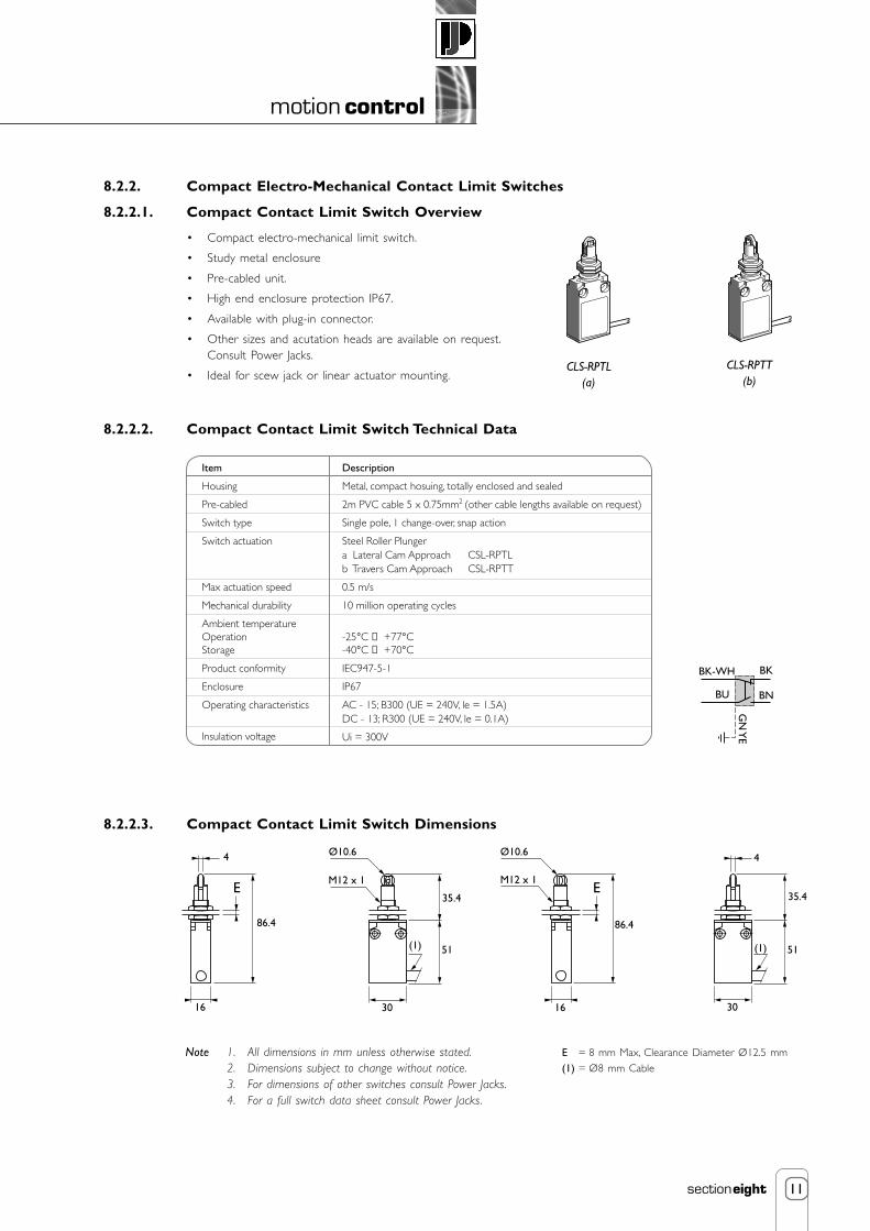
11
motion control
sectioneight
8.2.2. Compact Electro-Mechanical Contact Limit Switches
8.2.2.1. Compact Contact Limit Switch Overview
• Compact electro-mechanical limit switch.
• Study metal enclosure
• Pre-cabled unit.
• High end enclosure protection IP67.
• Available with plug-in connector.
• Other sizes and acutation heads are available on request.Consult Power Jacks.
• Ideal for scew jack or linear actuator mounting.
8.2.2.2. Compact Contact Limit Switch Technical Data
16
86.4
E E
30
51(1)
35.4
4
M12 x 1
Ø10.6Ø10.6
30
51(1)
35.4
16
86.4
4
M12 x 1
Note 1. All dimensions in mm unless otherwise stated.2. Dimensions subject to change without notice.3. For dimensions of other switches consult Power Jacks.4. For a full switch data sheet consult Power Jacks.
8.2.2.3. Compact Contact Limit Switch Dimensions
Item
Housing
Pre-cabled
Switch type
Switch actuation
Max actuation speed
Mechanical durability
Ambient temperatureOperationStorage
Product conformity
Enclosure
Operating characteristics
Insulation voltage
Description
Metal, compact hosuing, totally enclosed and sealed
2m PVC cable 5 x 0.75mm2 (other cable lengths available on request)
Single pole, 1 change-over, snap action
Steel Roller Plungera Lateral Cam Approach CSL-RPTLb Travers Cam Approach CSL-RPTT
0.5 m/s
10 million operating cycles
-25°C → +77°C-40°C → +70°C
IEC947-5-1
IP67
AC - 15; B300 (UE = 240V, le = 1.5A)DC - 13; R300 (UE = 240V, le = 0.1A)
Ui = 300V
CLS-RPTL(a)
CLS-RPTT(b)
E = 8 mm Max, Clearance Diameter Ø12.5 mm
(1) = Ø8 mm Cable
BK-WH
GN
YE
BN
BK
BU

12
motion control
sectioneight
8.2.3. Safety Related Electro-Mechanical Contact Limit Switches
8.2.3.1. Safety Related Contact Limit Switch Overview
• Positive break Normally Closed contacts - will not stick or weld shut.
• Watertight design to IP67 washdown requirements.
• Rugged corrosion resistant housing tolerants hostile environments.
• Safety system approved.
• Thermoplastic enclosure. Double insulated.
• Snap action with positive-break Normally Closed contact, approved for use insafety systems.
• Wiring compartment.
• Alternative actuators heads are available on request. Consult Power Jacks.
• Actuator heads can be repositioned in steps 4 x 90°
• Good resistance to oil and petroleum spirit.
• Actuating force: Min. 9 N.
• Positive break force: 19 N.
• Actuating speed with actuating angle 30° to switch axis. Snap action: Min. 20 mm/min, max. 1 m/s.
• Cable entry: Long Body - 1 cable entry, at end. Short Body - 2 cable entries from sides.
• Ideal for screw jack or linear actuator mounting.
8.2.3.2. Safety Related Contact Limit Switch Specification
** For the switch plunger.
Note 1. Technical Data subject to change without notice.2. For a full set of limit switch details consult Power Jacks.
Feature Description
Standards IEC/EN 60947-5-1; EN 1088; BG-GS-ET-15
Design EN 50047
Enclosure material Glass-fibre reinforced thermoplastic, self-extinguishing
Protection class IP 67 to IEC/EN 60529/DIN VDE 0470-1
Contact material Silver
Contact type Change-over with double break Zb, NC contacts with positive break
Switching system A IEC 60947-5-1; B BG-GS-ET-15; snap action, NC contacts with positive break
Termination Screw terminals for max. 2.5 mm2 cables (including conductor ferrules)
Rated impulse withstand voltage U imp 6 kV
Rated insulation voltage U i 500 V
Thermal test current I th 10 A
Utilisation category AC-15; DC-13
Rated operating current/voltage Ie/Ue 4 A/230 VAC; 2.5 A/400 VAC; 1 A/500 VAC; 1 A/24 VDC
Max. fuse rating 10 A (slow blow); 16 A (quick blow),
6 A (slow blow) as positive break position switch
Ambient temperature -30 °C → +80 °CMechanical life 20 million operations
Switching frequency Max. 5,000/h
Switching point accuracy -
Actuating speed ** Min. 10 mm/min
Contact break for complete stroke 2 x 2 mm
Bounce duration < 3 ms
Switchover time > 5.5 ms

13
motion control
sectioneight
8.2.3.3. Safety Related Contact Limit Switches Dimensions
Long Body
Short Body
Switch Contacts/Travel
Snap Action
Note 1. All dimensions in mm unless otherwise stated.2. Dimensions subject to change without notice.3. For dimensions of other switches consult Power Jacks.4. For a full switch data sheet consult Power Jacks.
0
13
21
14
22
1 NO
1 NC
2,5
1
4.8
613-1421-22
13-1421-22
p
58.5
3
30Ø26
22
20
4.3
48.5
Pg 13.513.5
30
2033
2648.45
M18 x 1
126
24
3.5
10
F
8.5
20
58
50
22 26
4
4.3
Pg 13.513.5
30
20
3326
48.45
M18 x 1
126
24
3.5
10
1
50.5
F
42
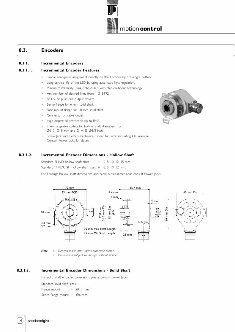
14
motion control
sectioneight
8.3. Encoders
8.3.1. Incremental Encoders
8.3.1.1. Incremental Encoder Features
• Simple zero-pulse assignment directly on the Encoder by pressing a button.
• Long service life of the LED by using automatic light regulation.
• Maximum reliability using opto-ASICs with chip-on-board technology.
• Any number of desired lines from 1 → 8192.
• RS422 or push-pull output drivers.
• Servo flange for 6 mm solid shaft.
• Face mount flange for 10 mm solid shaft.
• Connector or cable outlet.
• High degree of protection up to IP66.
• Interchangeable collets for hollow shaft diameters fromØ6 → Ø15 mm and Ø1/4 → Ø1/2 inch.
• Screw Jack and Electro-mechanical Linear Actuator mounting kits available.Consult Power Jacks for details
8.3.1.2. Incremental Encoder Dimensions - Hollow Shaft
Standard BLIND hollow shaft sizes = 6, 8, 10, 12, 15 mm.
Standard THROUGH hollow shaft sizes = 6, 8, 10, 12 mm.
For Through hollow shaft dimensions and cable outlet dimensions consult Power Jacks.
.
8.3.1.3. Incremental Encoder Dimensions - Solid Shaft
For solid shaft encoder dimensions please consult Power Jacks.
Standard solid shaft sizes:
Flange mount = Ø10 mm
Servo flange mount = Ø6 mm
Note 1. Dimensions in mm unless otherwise stated.2. Dimensions subject to change without notice.
72 mm
63 mm PCD
20 mm
3.3 mm3.2 mm
32.0
mm
31.5
mm
Dia
20°
26 mm
66.7 mm
22 m
mD
ia
66 m
m D
ia
60 mm Dia
2 mm
15 m
m D
ia(F
7)
13.5 mm
3.5 mm
2 mm
30 mm Max Shaft Length
15 mm Min Shaft Length

15
motion control
sectioneight
8.3.1.4. Incremental Encoder Technical Data
39 42 42 gcm2
12.8
6
mm Figure 1
42 48 54 gcm2
15
6
mm Figure 2
Feature DescriptionNumber of lines (Z) 1 → 8192Output driver RS 422 + push-pull outputsMass (kg) Solid shaft and hollow shaft approx. 0.3Moment of inertia of the rotor (gcm2) Face mount with 10 mm shaft 54
Servo flange with 6 mm shaft 48Through hollow shaft see Fig. 1
Blind hollow shaft see Fig. 2Measuring step (Degrees) 90/number of linesReference signal Number 1
90°or 180° electrical,logically
linked to K1 and K2Error limits (Degrees) Binary number of lines 0.035
Non-binary number of lines 0.046Measuring step deviation (Degrees) Binary number of lines 0.005 Non-binary number of lines 0.016Max. output frequency (kHz) RS 422 820
Push-pull output 200Max. angular acceleration (RAD/S2) 5 x 10⁵
Max. operating speed (MIN-1) Face mount and servo flange with shaft seal 6000Face mount and servo flange without shaft seal* 10000
Hollow shaft designs 3000Operating torque (Ncm) Face mount flange 10 mm shaft typ. 0.3
Servo flange 6 mm shaft typ. 0.2Through hollow shaft typ. 1.6
Blind hollow shaft typ. 0.4Start-up torque (Ncm) Face mount flange 10 mm shaft typ. 0.4
Servo flange 6 mm shaft typ. 0.25Through hollow shaft typ. 2.2
Blind hollow shaft typ. 0.6Permissible shaft loading, Radial 20Solid shaft (N) Axial 10Permissible movement of the Static radial movement ±0.5Drive element for hollow shafts (mm) Dynamic radial movement ±0.1
Static/dynamic axial movement ±0.5Bearing lifetime (Revolutions) 3.6 x 10⁹
Working temperature range (°C) -20 → +85Storage temperature range (°C) -40 → +100Permissible relative humidity(condensation not permitted)EMC to EN 50082-2 and EN 50081-2 Resistance to shocks (DIN IEC 68 Parts 2-27) (g/ms) 50/11Resistance to vibration (DIN IEC 68 Parts 2-6) (g/Hz) 20/10 → 150Protection class, Solid shafts Connector outlet with mating connector fitted IP 65Blind hollow shafts Cable outlet IP 66Through hollow shaft IP 64Operating voltage range see output driverNo-load operating current 10 → 32V typ. 100 mA 5 V typ. 120 mAOperation of zero-set (only with shaft stationary) ≥100 msInitialisation time after power on 40 ms
90%
Position
* In case, that shaft seal has been removed by customer.
Note 1. Technical Data subject to change without notice.

16
motion control
sectioneight
8.3.2. Absolute Encoders
8.3.2.1 Absolute Encoder Features
• Rugged, magnetic pick-up system.
• Rotary multiturn absolute encoder with integral gearbox, therefore a battery is not necessary.
• Basic resolution max. 8192 steps, 8192 revolutions.
• SSI, 25 bit (Synchronous Serial Interface).
• RS 422 configurable interface.
• Zero set push button.
• Electronically adjustable configurable interface.
• Compact dimensions.
• Highly shock-proof and vibration-proof.
• High degree of protection IP 67.
• Connector or cable outlet.
• Servo flange for 6 mm solid shaft.
• Face mount flange for 10 mm solid shaft.
• Blind hollow shaft: max. shaft diameter 15 mm. Option of using interchangeable collets, diametersfrom 6 to 12 mm, and 1/4 inch and 1/2 inch can be realised. Easy to install and no coupling needed.
• Screw Jack and Electro-mechanical Linear Actuator mounting kits available. Consult Power Jacks for details.
8.3.2.2. Absolute Encoder Dimensions - Hollow Shaft
8.3.2.3. Absolute Encoder Dimensions - Solid Shaft
For solid shaft encoder dimensions please consult Power Jacks.
Standard solid shaft sizes:
Flange mount = Ø10mm.
Servo flange mount = Ø6mm.
For cable outlet dimensions consult Power Jacks.
Note 1. Dimensions in mm unless otherwise stated.
2. Dimensions subject to change without notice.
72 mm
63 mm P.C.D.
20 mm
3.3 mm3.2 mm
32.0
mm
31.5
mm
Dia
20°
30 mm Max Shaft Length
15 mm Min Shaft Length 26 mm
73 mm
24 m
mD
ia66
mm
Dia
60 mm Dia
13 mm
15 m
m D
ia(F
7)
13.5 mm
3.5 mm
2 mm

17
motion control
sectioneight
Note Technical details subject to change without notice.
8.3.2.4. Absolute Encoder Technical Data
Feature
Shaft Type Solid Shaft with face mount/servo flange Blind Hollow Shaft
Communication type
Programmable code type
Programmable code direction
Shaft Size (mm) Ø6 or Ø10 Ø6 → Ø15
Number of steps per revolution
Number of revolutions
Measuring step (degrees
Error limits (degrees)
Repeatability (degrees)
Operating speed (min-1) 6000 3000
Position forming time (ms)
Max. angular acceleration (rad/s2)
Moment of inertia of the rotor (gcm2) 35 55
Operational torque with shaft sealing ring (Ncm) 1.8 0.8
Operational torque without shaft sealing ring (Ncm) 0.3 -
Start-up torque with shaft sealing ring (Ncm) 2.5 1.2
Start-up torque without shaft sealing ring (Ncm) 0.5 -
Maximum shaft loading radial/axial (N) 300/500 -
Permissible shaft movement of the drive element
Radial static/dynamic (mm) - ±0.3/±0.1
Axial static/dynamic (mm) - ±0.5/±0.2
Bearing lifetime (revolutions)
Working temperature range (°C)
Operating temperature range(°C)
Storage temperature range (°C)
Permissible relative humidity (%)
Mass (kg) 0.5 0.4
EMC
Resistance to shocks in the mounted state (DIN IEC 68 part 2-27)
Resistance to vibration in the mounted state (DIN IEC 68 part 2-6)
Degree of protection according to IEC 60529
With shaft sealing ring IP 67 IP 67
Without shaft sealing ring and encoder flange not sealed IP43 IP43
Without shaft sealing ring and encoder flange sealed IP65 -
Operating voltage range (VDC)
Recommended supply voltage (W)
Initialisation time (ms)
Signals connection
Interface signals
Clock+, Clock-, Data+, Data-
SET (electronic adjustment)
CW/CCW (step sequence in direction of rotation)
Description
SSI (Synchronous Serial Interface) 25bit
Gray / Binary
cw/ccw
8192
8192
0.043
±0.25
0.1
0.15
5 x 10⁵
3.6 x 10⁹
-20 → +85
-40 → +100
-40 → +100
98
EN 50081 part 2 and EN 50082 part 2
100/(6ms)
20 / (10 → 2000 Hz)
10 → 32
0.8
1050 (from the moment the supply voltage is applied, this is thetime which elapses before the data word can be correctly read in.)
12-way connector, potential-free with respect to housing.
SSI max clock frequency: 1 MHz i.e. min duration of low level(clock+): 500 ns.
»H« - active (L ≅ 0 → 4.7 V; H ≅ 10 → Us V)
»L« - active (L ≅ 0 → 1.5 V; H ≅ 2.0 → Us V)

18
motion control
sectioneight
1 2 3 4 5
The position indicator can be furnished as a complete actuator positioning kitwhich includes digital position indicator, incremental shaft encoder with flyinglead or connector and cable (variable cable length available), actuator couplingand worm shaft adapter (for installing the encoder) and mounting bracket.Electrical connections are made at the rear to the unit to terminal strips.
8.4. Position Indicators
8.4.1. Digital Position Indicators
8.4.1.1. Programmable Digital Position Indicator T-735
• For use in positioning applications with Power Jacks actuators.
• Displays position of lifting screws in increments of 0.01 mm or 0.001”.
• Brilliant 18.5 mm high Dual colour display. Red or Green user definede.g. Green normal operation and Red position limit reached.
• User-Friendly interface programmable from front panel via four rubber keys with help function on secondary7 mm high display.
• Non-volatile memory retains all programmed information and count value in the event of power loss.
• Two adjustable up/down output limits (pre-sets), with a 0 → ±99999 range, can act as limit switches.
• Five digit input scaling 0.0001 → 9.9999, programmable decimal point location and lead zero blanking.
• Display convertible to metric, imperial or other units of measurement.
• For position indication on actuator applications Power Jacks recommend feedback from a shaft encoder forprecise, reliable and maintenance-free operation.
• Programmable front panel functions may be locked out to prevent unauthorised adjustment.
• Reset capability allows reset to zero from front panel.
Inputs
• Count inputs - 2 channels A and B ideal for encoder connection. Capable of TTL, 30V DC max. at 10 kHz.
• Digital inputs - 2 terminals (NPN) can be used to activate pre-configured functionality e.g. remote reset andsecurity mode.
Outputs
• 2 NPN outputs activated by each pre-set. Two red LED’s on panel indicate activation.
• 2 Relay outputs (Normally Closed or Open) activated by each pre-set.
• Sensor power supply 12 VDC (unregulated), 125 mA max., ripple < 0.5V.
User Parameters
• Up/down travel limits (pre-sets). • Voltage/Current output definition and scaling.
• Calibration factor. • Serial communication settings.
• Decimal position. • Display colour settings.
• Reset value -19999 → 99999 (default is zero). • Pre-set lock on/off.
• Filter speed 20, 200 or 10 kHz. • Help display on/off.
• Front panel reset enable/disable.
• Power supply 90 → 264 V AC 50/60 Hz or 20 → 50 V AC/DC.
• DIN housing 48 x 96 mm, mounting depth 100 mm. Panel 45 +0.5 mm x 92+0.5 mm, 12 mm max. thick.
• Operating temperature 0°C → +55°C. Relative humidity 20% → 90%, non-condensing.
• Protection - front panel IP66.
• CE marked and safety to DIN EN 61010 part 1.
Options
• Linear output 0/4-20mA, 0/1-5 V, 0/2-10 V, 10 bit resolution.
• RS485 Serial interface. Open ASC11, Master-slaveup to 99 zones.
50 kN Metric Actuator
EncoderAnti-Rotation Pin
PositionIndicator
Protective Cover
Example Illustration
DriveShaft
Adaptor
Encoder(Hollow Shaft)
Plug-in connectorand cable

19
motion control
sectioneight
8.4.2. Analogue Postion Indicators
8.4.2.1. Transducer SKA-6200-T Remote Screw Position Indicator
The SKA-6200-T position transducer is designed to mount on the end of any SKA-6000-T limit switch. Its major component is apotentiometer which has a slider tap and a tap at each end of the element.
Gear ratios of 10:1, 20:1 and 40:1 allow for a wide range of raises. Total resistance of element is 500 ohms. Other resistance’s areavailable on special order. Consult Power Jacks for additional information.
Note 1. Included with each position transducer are the following mounting parts:3 socket head cap screws.3 lock washers.(position transducer shipped assembled in separate package to be installed at site by customer.)
2. Transducer supplied with black anodised finish as standard.
Position transducer available in following models:
Model No.
SKA-6200-T-10SKA-6200-T-20SKA-6200-T-40
GearRatio
10 :120 :140 :1
Max. TurnsTransducerWorm Shaft
100200400
CCW and CW refer to worm shaftrotation as viewed from slotted end.
Worm Gear(40 mm)
Housing
Potentiometer (10 Turn)
Worm
Worm Shaft
CWCCW2 1/4"
3 1/8"
1 1/4"
STD 1/2" NPT
3 13/16" ±1/16"
2 11/16"
19/32"
19/32"19/32"
19/32"7/8"27/32"
7/8"
7/8"7/8"
2 7/8"
9/32" DiaThree Holes
B
A
B
CCW
CWS
A
2 1/2"
.300" Dia
.125"
Section A-A
Power Rating: 2 W at 40°C, 0 W at 0°C, Total Resistance = 500 ohms
S (Slider)
Section B-B

20
motion control
sectioneight
8.5. Control Panels
Power Jacks offer control systems for machine screw and ball screw actuators. These control panels provide the option of jogging(inching), or maintained operation, when specified as part of a Power Jacks linear positioning system. The control panels are built tointernational standards to individual customer requirements with numerous options available, consult Power jacks for details.
8.5.1. Example of Actuator Control System
Two mechanically linked Sym-metric actuator systems are electronically synchronised for speed and position control using thePowerMAX 5000 frequency converter with integral control card. The PowerMAX 5000 controls the systems by controlling the motionof each motor comparing actual and required performance via a closed feedback loop. This is provided by the encoders in each motorfeeding back direct to the PowerMAX 5000. Each actuator system is referenced from a datum point signalled by the RLS-51 limitswitch on each system. The RLS-51 also provides end of travel limits that are installed for safety. Each frequency conver ter has anintegral motion control card, which are linked together and arranged in a master-slave relationship for control purposes.
This type of system is used where mechanical links to all linear motion components are not possible and where complete motioncontrol is required for a specific process. For example a platform lift where a series of precise positions are required along theactuators stroke where the platform must stop for a specified time with variable speeds at the end of each stroke and a certainnumber of cycles per complete operation. All of which can be programmed into the unit with key user parameters accessible via thecontrol keypad.
For advice on specifying the best solution for your application consult Power Jacks Ltd.
PowerMAX 5000Frequency Converterwith integral motion control card. Two bookstyle units linked to sychronise a 2 axis system for speed and position control.
Neeter Drive Spiral Bevel Gearbox
RLS51 limit switchprovides extreme end of travel limits for each actuator system and a datum reference point for position control.
Sym-metric translating screw actuators mechanically linked in a two actuator system.
Spacer coupling (self supporting)
AC motor with integralbrake and encoder

POWER JACKSGroupmanufacturers of precision screw jacks, actuators and gearboxes
9. engineers reference
Formulae
Conversion Factors
Enclosure Ratings
Nut, Bolts and Key Tables
Property Tables
Warranty
1
engineers reference
sectionnine
Contents
9.1. Useful Formulae for Actuator Calculations 2
9.2. Useful Formulae for Power Transmission Calculations 4
9.3. Conversion Factors 6
9.4. Enclosure Ratings 8
9.5. Metric Nuts and Bolts 9
9.6. Metric Square and Rectangular Parallel Keys 10
9.7. Physical Property Values 11
9.8. Standard SI Prefixes 11
9.9. Limitations of Responsibility 12
9.10. Warranty 12

2
engineers reference
sectionnine
RPM of Worm Shaft * Lifting Screw Lead (mm)
Gear Ratio
9.1. Useful Formulae for Actuator Calculations
9.1.1. Metric Units
9.1.1.1. Lifting Screw Lead
Lifting Screw lead (mm) = Screw Pitch (mm) *Number of Starts on Lifting Screw
Input Torque (Nm) =
Raise Rate (mm/min) =
Raise Rate (mm/min) =
9.1.1.3. Calculation of Actuator Input Torque
Input Power (kW) * 9550
Input Speed (rpm)Input Torque (Nm) =
Load (kN) *Lifting Screw Lead (mm)
2 * π * Actuator Efficiency * Actuator Gear Ratio
9.1.1.4. Calculation of Actuator Input Power
Input Power (kW) =Load (kN) * Raise Rate (mm/min)
60000 * Actuator Efficiency
Input Power (kW) =Load (kN) * Lifting Screw Lead (mm) * Input Speed (rpm)
60000 * Actuator Efficiency * Actuator Gear Ratio
RPM of Worm Shaft
Turns of Worm for 1mm Raise
or alternatively
or alternatively
or alternatively
9.1.1.2. Calculation of the Raise Per Minute with a Given Worm Shaft Speed
When the worm shaft speed is known, the distance the load can be raised per minute can be determined with this formula:
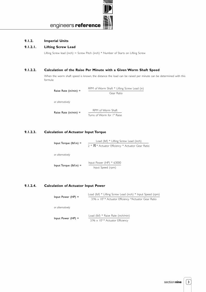
3
engineers reference
sectionnine
or alternatively
RPM of Worm Shaft
Turns of Worm for 1" Raise
RPM of Worm Shaft * Lifting Screw Lead (in)
Gear Ratio
Raise Rate (in/min) =
Raise Rate (in/min) =
9.1.2.3. Calculation of Actuator Input Torque
Input Torque (lbf.in) =Load (lbf) * Lifting Screw Lead (inch)
2 * π * Actuator Efficiency * Actuator Gear Ratio
Input Power (HP) * 63000
Input Speed (rpm)Input Torque (lbf.in) =
or alternatively
9.1.2.4. Calculation of Actuator Input Power
Input Power (HP) =Load (lbf) * Lifting Screw Lead (inch) * Input Speed (rpm)
3.96 x 10⁵ * Actuator Efficiency *Actuator Gear Ratio
or alternatively
Input Power (HP) =Load (lbf) * Raise Rate (inch/min)
3.96 x 10⁵ * Actuator Efficiency
9.1.2. Imperial Units
9.1.2.1. Lifting Screw Lead
Lifting Screw lead (inch) = Screw Pitch (inch) * Number of Starts on Lifting Screw
9.1.2.2. Calculation of the Raise Per Minute with a Given Worm Shaft Speed
When the worm shaft speed is known, the distance the load can be raised per minute can be determined with thisformula:

4
engineers reference
sectionnine
9.2. Useful Formulae for Actuator Calculations
9.2.1. Power
9.2.2. Torque
Lifting Motion
FR = µ * m * g FR = µ * W
T * n9550
P =T * n63000
P =
FR * v1000
P =FR * v33000
P =
m * g * vη * 1000
P = W * vη * 33000
P =
Linear Motion
Rotary Motion
Metric Imperial
T = FR * r T = T * r
P * n9550
T =P * n
63000T =
Symbol
P
T
FR
m
W
g
ν
η
µ
n
r
Power
Torque
Resistance due to Friction
Mass
Weight
Gravitational Acceleration
Velocity
Efficiency
Coefficient of Friction
Rotational Speed
Radius
kW
Nm
N
kg
-
9.81 ms-2
ms-1
decimals
decimals
rpm
m
HP
lbf.in
lbf
-
lb
32.185 ft-2
ft/min
decimals
decimals
rpm
in
Quantity Metric Units Imperial Units

5
engineers reference
sectionnine
9.2.4. Acceleration or Braking Time
9.2.3. Moment of Inertia
1
2J = * m * rod
2
1
32J = * π * ρ * dod
4
J = 0.098 * ρ * I *dod4
1
2WK2 = * W * rod
2
π32
WK2 = * r * I * dod4
WK2 = 0.1 * ρ * I *dod4
1
32J = * π * ρ * I * (dod
4 -did4)
J = 0.098 * ρ * I * (dod4 -did
4)
1
2WK2 = * W * (rod
2 -rid2)
π32
WK2 = * ρ * I * (dod4 -did
4)
WK2 = 0.1 * ρ * I * (dod4 -did
4)
1
2J = * m * (rod
2 -rid2)
Solid Cylinder
Hollow Cylinder
Metric Imperial
J * n
9.55 * Tacctacc =
WK2 * n
308 * Tacctacc =
Symbol
J
WK2
Tacc
m
W
rod
rid
dod
did
I
ρ
tacc
n
Moment of Inertia (metric)
Moment of Inertia (imperial)
Torque due to Acceleration or Braking
Mass
Weight
Outer Radius
Internal Radius
Outer Diameter
Internal Diameter
Length
Density
Time for Acceleration or Braking
Rotational Speed
kgm2
-
Nm
kg
-
m
m
m
m
m
kg/m3
s
rpm
-
lb.ft2
lbf.ft
-
lb
ft
ft
ft
ft
ft
lb/ft3
s
rpm
Quantity Metric Units Imperial Units

6
engineers reference
sectionnine
9.3. Conversion Factors
Force / Weight
1 N
1 kgf
1 kp
1 lbf
Mass
1 kg
1 Tonne
1 lb
1 Ton (Short)
1 Ton
Length
1 m
1 mm
1 inch
1 ft
m
1
0.001
0.0254
0.3048
mm
1000
1
25.4
304.8
inch
39.370
0.03937
1
12
ft
3.2808
3.28 x 10⁻³
0.0833
1
kg
1
1000
0.45355937
907.185
1016.05
Tonne
0.001
1
4.536 x 10⁻⁴
0.907185
1.016
lb
2.2046
2204.6
1
2000
2240
Ton
9.842 x 10⁻⁴
0.9842
4.464 x 10⁻⁴
0.8929
1
Ton (Short)
1.1023 x 10⁻³
1.1023
5 x 10⁻⁴
1
1.120
Speed
1 m/s
1 mm/s
1 ft/s
1 in/s
m/s
1
0.001
0.3048
0.0254
mm/s
1000
1
304.8
25.4
ft/s
3.2808
3.28 x 10⁻³
1
0.0833
in/s
39.37
0.03937
12
1
N
1
9.80665
9.80665
4.44822
kgf
0.1019716
1
1
0.45359237
kp
0.120
1
1
0.4536
lbf
0.224809
2.2046
2.2046
1
Torque / Work
1 Nm
1 kfg.cm
1 lbf.in
1 lbf.ft
Nm
1
9.80665 x 10⁻²
0.1129848
1.35582
kgf.cm
10.19716
1
1.1521
13.825
lbf.in
8.8507
0.8679
1
12
lbf.ft
0.73756
0.07233
0.08333
1

7
engineers reference
sectionnine
9.3. Conversion Factors
Stress / Pressure
1 MPa (N/mm2)
1 N/m2
1 kg/cm2
1 lbf/inch2
1 lbg/ft2
1nertia
kg.m2 (mr2)
1 kpms2
1 lbf.ft2 (WK2)
1 lbf.in2 (WK2)
Power
1 kW
1 Nm/min
1 kgf.m/s
1 hp
1 lbf.ft/min
kW
1
1.667 x 10⁻⁴
9.807 x 10⁻³
0.7457
2.261 x 10⁻⁵
Nm/min
60000
1
588.6
44741
1.3566
kgf.m/s
10.20
1.699 x 10⁻³
1
76.04
2.3056 x 10⁻³
hp
1.34
2.235 x 10⁻⁵
0.01315
1
3.03 x 10⁻⁵
lbf.ft/min
44220
0.7374
433.73
33000
1
kg.m2 (mr2)
1
9.807
0.0421
2.9264 x 10⁻⁴
kpms2
0.10197
1
4.30 x 10⁻³
0.6192
lbf.ft2 (WK2)
23.73
232.6
1
6.944 x 10⁻³
lbf.in2 (WK2)
3417.2
33488
144
1
Temperature
T °F
T °C
(T °C x 1.8) + 32°
(T °F -32) / 1.8
MPa (N/mm2)
1
1 x 10⁻⁶
9.807 x 10⁻²
9.8947 x 10⁻³
4.7879 x 10⁻⁵
kg/cm2
10.2
10.2 x 10⁻⁶
1
0.070307
0.488 x 10⁻³
N/m2
1 x 10⁻⁶
1
9.81 x 10³
6.89 x 10³
47.88026
lbf/inch2
145.039
145 x 10-6
14.2233
1
6.94 x 10⁻³
lbf/ft2
20885.6
20.88 x 10⁻⁶
2.05 x 10
144
1

8
engineers reference
sectionnine
9.4. Enclosure Ratings
9.4.1. IEC Ratings
1 When only one characteristic numeral is used the second numeral is replaced by an ‘X’.
2 A ‘W’ inserted after the ‘IP’ indicates suitable for a specified weather condition (conditions and features specified by manufacturer).
9.4.2. NEMA and IEC Equivalent Enclosures
Since the IEC degree of protection for enclosed equipment is defined differently from NEMA type enclosure protection, andmethods of test are different, exact correlation between IEC IP-type designations and NEMA types is not possible. It is possible tomake rough comparisons, which may result in certain applications. The common NEMA type designations compare with IECdesignations as follows:
No special protection
A large surface of the body, such as hand (but no protectionagainst deliberate acces.) Solid objects >50 mm diameter.
Fingers or similar objects not exceeding 80mm in length.Solid objects >12mm in diameter.
Tools, wires, etc. of diameter or thickness >2.5mm.Solid objects >1mm diameter.
Wires or strips of thickness >1mm.Solid objects exceeding 1mm diameter.
Ingress of dust is not totally prevented, but dust does notenter in sufficient quantity to interfere with satisfactoryoperation of the equipment.
No ingress of dust.
No special protection
Dripping water (vertically falling drops).
Vertically dripping water when the enclosure is tilted at anyangle up to 15º from its normal position.
Water falling as a spray at an angle of 60º from the vertical.
Water splashed against the enclosure from any direction.
Water projected by a nozzle against the enclosure.
Water from heavy seas or projected in powerful jets.
Ingress of water in a harmful quantity not possiblewhen the enclosure is immersed under defined conditions ofpressure and time.
Submersible under defined conditions of pressure and time.
1st Digit : Solid Ingress 2nd Digit : Liquid Ingress
0
1
2
3
4
5
6
0
1
4
5
6
7
8
2
3
IP2XProtected against solid objects greater than 12mm.Test: Metallic test finger and 12mm sphere tests. No IEC rust resistance test.
Dust protected. Protected against splashing water. Test: Dustand oscillating sprinkler tests. No IEC rust resistance test.
Protected against solid objects greater than 2.5mm. Protectedagainst splashing water. Test: 2.5mm rod and oscillatingsprinkler tests. No IEC rust resistance or icing tests.
Dust-tight and protected against water jets.Test: Dust and spray nozzle tests. no rust resistance orexternal icing test.
Dust-tight and protected against water jets.Test: Dust and spray nozzle tests. No rust resistance orexternal icing test.
No IEC equivalent.
No IEC equivalent.
Dust-tight and protected against dripping water.Test: Dust and rain simulator tests. No IEC rust resistance test.
Dust-tight.Test: Dust test. No IEC oil-tightness or rust resistance tests.
NEMA 1General protection of people from live parts. Protection against falling dirt. Test: 1/8" to 1/2" (3.175to 12.7mm) rod entry test and rust resistance tests.
Dust-tight and sleet resistant.Test: Rain, dust, external icing and rust resistance test.
Rain-proof and sleet resitant.Test: Rod entry 1/8" to 1/4" (3.175 to 6.35mm), rain, external icing and rust resistance tests.
Water-tight and dust-tight.Test: Hosedown, rust-resistance and external icing tests.
Water-tight, dust-tight and corrosion resistance.Test: Hosedown, corrosion resistance and external icing tests.
Hazardous gas.
Hazardous dust.
Dust-tight and drip-tight.Test: Drip, dust and rust resistance tests.
Oil tight and dust tight.Test: Oil-tightness and rust-resistance tests.
NEMA Type Nearest IEC Equivalent
NEMA 3
NEMA 3R
NEMA 4
NEMA 4X
NEMA 7
NEMA 9
NEMA 12
NEMA 18
1
IP54
IP34
IP65
IPW65
-
-
IP61
IP6X 1
2

9
engineers reference
sectionnine
9.5. Metric Nuts and Bolts
A
R
H
D
T
D
W
K
Note: 1. All dimensions in millimetres.
2. Sizes in brackets are non-preferrred standards.
3. All dimensions are maximum sizes.
Hexagon Bolt
Socket Head Cap Screw
Threaded End
Length
Threaded End
Length
Thread Size
D
M3
M4
M5
M6
M8
M10
M12
(M14)
M16
(M18)
M20
(M22)
M24
(M27)
M30
(M33)
M36
(M39)
M42
Pitch
0.50
0.70
0.80
1.00
1.25
1.50
1.75
2.00
2.00
2.50
2.50
2.50
3.00
3.00
3.50
3.50
4.00
4.00
4.50
A
5.50
7.00
8.00
10.00
13.00
17.00
19.00
22.00
24.00
27.00
30.00
32.00
36.00
41.00
46.00
50.00
55.00
60.00
65.00
H
2.125
2.925
3.650
4.150
5.650
7.180
8.180
9.180
10.180
12.215
13.215
14.215
15.215
17.215
19.620
21.260
23.260
25.260
26.260
K
2.40
3.20
4.00
5.00
6.50
8.00
10.00
11.00
13.00
15.00
16.00
18.00
19.00
22.00
24.00
26.00
29.00
31.00
34.00
R
5.50
7.00
8.50
10.00
13.00
16.00
18.00
21.00
24.00
27.00
30.00
33.00
36.00
40.00
45.00
50.00
54.00
-
63.00
T
3.00
4.00
5.00
6.00
8.00
10.00
12.00
14.00
16.00
18.00
20.00
22.00
24.00
27.00
30.00
33.00
36.00
-
42.00
W
2.5
3.0
4.0
5.0
6.0
8.0
10.0
12.0
14.0
14.0
17.0
17.0
19.0
19.0
22.0
24.0
27.0
-
32.0
Hexagon Bolts & Nuts Sockets Head Cap Screw
Hexagon Nut

10
engineers reference
sectionnine
9.6. Metric Square and Rectangular Parallel Keys
Enlarged Detail of Key and Keyways
X
X
B
H
T2T1
D - T1 D + T2
Section X-X
T2
T1
R
H/2H/2
Note: For full range and further informtion refer BS 4235: Pt 1: 1972
SymbolNominalDiameter
D
Key Keyway
B x Hwidth
xthick-ness
Shaft(H9)
Over Incl
Free Normal Shaft, T1
DepthWidth, B
Tolerance for class of fitNom
Radius, R
Hub, T2Close andInterference
Hub(D10)
Shaft(N9)
Hub(Js9)
Shaft andHub(P9)
Nom. Tol. Nom. Tol. Max. Min.
6
8
10
12
17
22
30
38
44
50
58
65
75
85
95
110
130
150
170
8
10
12
17
22
30
38
44
50
58
65
75
85
95
110
130
150
170
200
2
3
4
5
6
8
10
12
14
16
18
20
22
25
28
32
36
40
45
+0.025
0
+0.030
0
+0.036
0
+0.043
0
+0.052
0
+0.062
0
+0.060
+0.020
+0.078
+0.080
+0.095
+0.040
+0.120
+0.050
+0.149
+0.065
+0.180
+0.080
-0.004
-0.029
0
-0.030
0
-0.036
0
-0.043
0
-0.052
0
-0.062
+0.012
-0.012
+0.015
-0.015
+0.018
-0.018
+0.021
-0.021
+0.026
-0.026
+0.031
-0.031
-0.006
-0.031
-0.012
-0.042
-0.015
-0.051
-0.018
-0.061
-0.022
-0.074
-0.022
-0.088
1.2
1.8
2.5
3.0
3.5
4.0
5.0
5.0
5.5
6.0
7.0
7.5
9.0
9.0
10.0
11.0
12.0
13.0
13.0
+0.1
0
+0.2
0
+0.3
0
+0.1
0
+0.2
0
+0.3
0
0.08
0.16
0.25
0.40
0.70
0.16
0.25
0.40
0.60
1.00
1.0
1.4
1.8
2.3
2.8
3.3
3.3
3.3
3.8
4.3
4.4
4.9
5.4
5.4
6.4
7.4
8.4
9.4
10.4
2 x 2
3 x 3
4 x 4
5 x 5
6 x 6
8 x 7
10 x 8
12 x 8
14 x 9
16 x 10
18 x 11
20 x 12
22 x 14
25 x 14
28 x 16
32 x 18
36 x 20
40 x 22
45 x 25
D

11
engineers reference
sectionnine
9.7. Physical Property Values, at 20°C
9.8. Standard SI Prefixes * †
* If possible use multiple and submultiple prefixes in steps of 1000.
† Spaces are used in SI instead of commas to group numbers to avoid confusion with the practise in some Europeancountries of using commas for decimal points.
‡ Not recommened but sometimes encountered.
Material
Density, ρ (kg/m3)
Young's Modulus, E
(GN/m2)
Shear Modulus, G
(GN/m2)
Bulk Modulus, K
(GN/m2)
Poisson's Ratio, ν
Coefficient of Thermal
Expansion x 10-6/K
Specific Heat J/kg K
Carbon Steel
7860
207
79.3
172
0.292
12
460
Brass 65/35
8450
105
38
115
0.35
19
420
Copper
8910
119
44.7
130
0.326
17
420
Stainless Steel
7750
190
73.1
178
0.305
14
460
Aluminium Alloys
2710
710
26.2
57.5
0.334
22
920
Name
exa
peta
tera
giga
mega
kilo
hecto
deca
deci
centi
milli
micro
nano
pico
femto
atto
Symbol
E
P
T
G
M
k
h
da
d
c
m
µ
n
p
f
a
Factor
1 000 000 000 000 000 000 = 1018
1 000 000 000 000 000 = 1015
1 000 000 000 000 = 1012
1 000 000 000 = 109
1 000 000 = 106
1 000 = 103
100 = 102
10 = 101
0.1 = 10-1
0.01 = 10-2
0.001 = 10-3
0.000 001 = 10-6
0.000 000 001 = 10-9
0.000 000 000 001 = 10-12
0.000 000 000 000 001 = 10-15
0.000 000 000 000 000 001 = 10-18
‡
‡
‡
‡
Note: Values given are representative. Exact values may vary with composition and processing, sometimes greatly.

12
engineers reference
sectionnine
9.9. Limitation of Responsibility
The ratings given in this catalogue were compiled using standard engineering procedures. The ratings are designed to guide thecustomer in the selection of a unit. We do not guarantee the ratings in specific applications. Prototype testing of every application isrecommended before production. Our engineering facilities are available for consultation at all times. Please ask us for assistance withlinear motion and drive application problems. This catalogue is designed to assist in the selection of a suitable linear motion or powertransmission product for economical, long and trouble free service.
Due to Power Jacks policy of continuous improvement designs may be subject to change without notice. Please ask for certifieddrawings.
9.10. Warranty
Subject to the condition stated herein. Power Jacks will repair or replace, without charge, any parts proven to Power Jacks satisfactionto have been defective in material or workmanship. Claims must be made within one year after date of shipment. Power Jacks will notrepair or replace any parts that become inoperative because of improper maintenance, eccentric loading, overloading, chemical orabrasive action, excessive heat, or other abuse. Equipment and accessories not of Power Jacks manufacture are warranted only to theextent that they are warranted by the manufacturer, and only if the claimed defect arose during normal use, application and service.Equipment, which has been altered or modified by anyone without Power Jacks authorisation, is not warranted by Power Jacks. EXCEPTAS STATED HEREIN, POWER JACKS MAKES NO OTHER WARRANTIES, EXPRESS OR IMPLIED INCLUDING WARRANTIES OFMERCHANTABILITY AND FITNESS FOR A PARTICULAR PURPOSE.
WARNING: The equipment shown in this catalogue is intended for industrial use only and should not be used to lift, support, orotherwise transport people unless you have a written statement from Power Jacks Limited which authorises the specific unit as used inyour application suitable for moving people.
© Power Jacks Limited 1987, Aberdeenshire, Scotland, United Kingdom.
© Neeter Drive is a trading name of Power Jacks Limited.
© Precision Actuation Systems is a Power Jacks Company.
© Duff-Norton Company 1986, Charlotte, North Carolina, USA.
© Youngs Lifting is a trading name of Power Jacks Limited.
© Fortune Engineering is a trading name of Power Jacks Limited.
© Rolaram® is a trademark of Power Jacks Limited.
All rights reserved by Power Jacks Limited. May not be copied in whole or in part.

screw jacks • linear actuators • screw drives • bevel gearboxes • reduction gearboxes • couplings & drive shafts • electric motors • motion control PJLMPTDG - 02
PowerJacksLimitedMain Sales Office and ProductionSouth Harbour RoadFraserburgh AB43 9BZScotland UK
t +44 (0) 1346 513131f +44 (0) 1346 516827e [email protected]
linearmotion
andpow
ertransm
issiondesig
nguide
distributed by:
power jacks worldwide
www.powerjacks.com
POWER JACKSGroupmanufacturers of precision screw jacks, actuators and gearboxes
PO
WE
R JA
CK
S