LINEAR MOTION SHAKER - H-Screening · linear motion shaker general operations, maintenance and...
22
LINEAR MOTION SHAKER GENERAL OPERATIONS, MAINTENANCE AND SPARE PARTS MANUAL FOR KEMTRON LINEAR MOTION SHAKERS Revision D
Transcript of LINEAR MOTION SHAKER - H-Screening · linear motion shaker general operations, maintenance and...

LINEAR MOTION SHAKER GENERAL OPERATIONS, MAINTENANCE AND SPARE PARTS
MANUAL FOR KEMTRON LINEAR MOTION SHAKERS Revision D

Page 2 of 22
TABLE OF CONTENTS
1) Introduction ...................................................................................... 3
2) Operation .......................................................................................... 3
a) Shaker Base Assembly .................................................................. 5
b) Vibrator Motors ............................................................................ 8
c) Screens .......................................................................................... 10
d) Moving .......................................................................................... 13
3) Maintenance ..................................................................................... 14
4) Troubleshooting ................................................................................ 17
5) Shaker Parts Breakdown ................................................................... 19
6) Vibrator Motor Fastening System ..................................................... 20

Page 3 of 22
1. Introduction KEMTRON Technologies, Inc. manufactures a wide variety of shakers. Whether it is a standalone unit or combined with our packaged recycling systems, KEMTRON’s shakers are built to be reliable and durable. Although the shakers differ in geometric configuration, such as physical size, number of decks, number of screens, etc., the basic operations and maintenance principles remains the same.
Several shaker models incorporated in our mud recycling systems are shown below. As a standard, all use pre-‐tensioned screens with a wedge/bar fastening system for ease of installation. Consequently, KEMTRON can configure each shaker to accommodate hook-‐strip screens and wedge-‐wire screens, upon customer request.
KTL-‐448 AG Four Panel Shaker KTL-‐48 STD Three Panel Shaker
2. Operation The Linear Motion Shaker is the backbone of a primary solid/liquid separation system. It is designed to remove course solids from a liquid to be recovered or recycled. This can take the form of dewatering coal tailings in a mining operation, separation of cuttings from drilling mud, and/or the cleaning of wastewater in a waste treatment facility. It accomplishes this by using Linear Motion Vibrator Motors and a tight screening surface.
The Vibrator Motors are designed in such a way as to produce a vertical and horizontal linear motion causing the liquid to vibrate up and down on the screens causing the heavier solids to discharge off the unit and the fluid to be recycled.

Page 4 of 22
CAUTION The shaker base must always be level. This is imperative to allow even
distribution of the liquid flow across the screening surface.
Key Shaker Components

Page 5 of 22
a. Shaker Base Assembly
The Shaker Base Assembly (“basket”) is the support structure for the shaker bed. The screens, vibrator motors are attached to the shaker bed. KEMTRON’s shaker basket is constructed of ASTM A36 plate steel that has been seal welded. This ensures maximum durability in any industrial setting. As an alternative, KEMTRON can also manufacture its baskets using 304 Stainless Steel. All carbon steel baskets are coated with a high-‐quality industrial coating that requires annual upkeep to ensure that corrosion does not attack the weldments or base metal. It is imperative that the base metal and coating be inspected on an annual basis.
The Shipping Brackets are provided to secure the Shaker bed during transport. (See Figure 1). Shipping brackets are typically highlighted with red paint and a yellow warning label. This may not always be the case, so close inspection of the shaker upon receipt is recommended.
WARNING
Shipping brackets MUST be attached prior to transporting.
Do NOT operate the Shaker with the Shipping Brackets bolted. This will cause damage to the shaker bed and host equipment.

Page 6 of 22
There are four (4) Deck Springs located around the shaker. These are specially designed to isolate the bed vibration from the host equipment and shaker carriage. A molded polyurethane washer (a.k.a. “fabric washer”) is used on each end of each spring for isolation and to prevent metal to metal contact of the spring with the shaker basket and carriage. As Deck Springs are powder-‐coated carbon steel, it is important that the spring condition be reviewed every month for visible signs of surface cracks, corrosion, and/or plastic deformation.
The Jack Assembly is designed to increase or decrease the shaker bed deck angle. This is done with the use of the furnished Jack Wrench. The Deck Angle plays an important role in shaker operation. The higher the deck angle the more residence time the cuttings have on the screens, thus the drier the solids effluent.
o A 0° to -‐1° angle is recommended for conveyance of sticky solids generated while drilling reactive clays.
o A +2° to +3° angle is recommended when fine mesh screens (i.e. KPT-‐110 to KPT-‐140) are used while drilling hard shale formations. A maximum +5° is provided. The grinding of solids and excessive screen wear to the first panel in the pool area at the back of the Shaker can result from extended use at higher angles.
Page 7 of 22
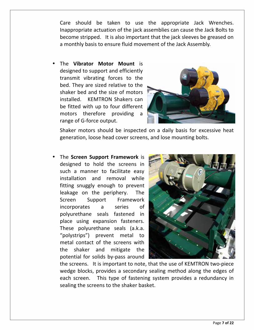
Care should be taken to use the appropriate Jack Wrenches. Inappropriate actuation of the jack assemblies can cause the Jack Bolts to become stripped. It is also important that the jack sleeves be greased on a monthly basis to ensure fluid movement of the Jack Assembly.
The Vibrator Motor Mount is designed to support and efficiently transmit vibrating forces to the bed. They are sized relative to the shaker bed and the size of motors installed. KEMTRON Shakers can be fitted with up to four different motors therefore providing a range of G-‐force output.
Shaker motors should be inspected on a daily basis for excessive heat generation, loose head cover screens, and lose mounting bolts.
The Screen Support Framework is designed to hold the screens in such a manner to facilitate easy installation and removal while fitting snuggly enough to prevent leakage on the periphery. The Screen Support Framework incorporates a series of polyurethane seals fastened in place using expansion fasteners. These polyurethane seals (a.k.a. “polystrips”) prevent metal to metal contact of the screens with the shaker and mitigate the potential for solids by-‐pass around the screens. It is important to note, that the use of KEMTRON two-‐piece wedge blocks, provides a secondary sealing method along the edges of each screen. This type of fastening system provides a redundancy in sealing the screens to the shaker basket.

Page 8 of 22
The Screen Support Framework should be inspected on a monthly basis to check for visible signs of surface cracking, plastic deformation, and corrosion. Corrosion can cause the fastening system to weaken.
All polystrips should be inspected on a monthly basis. Loose or damaged polystrips can lower screen life and cause cuttings bypass around the screen.
In a few applications, some KEMTRON shakers will not take advantage of polystrips, but will use screens with a integral seal.
b. Vibrator Motors
The Vibrator Motors are designed with a set of counter weights on each side. A variety of vibrator motors are available depending on the operating conditions and the required G-‐force.
The Counter Weights are factory set for optimum performance. Each Vibrator Motor has a left and right side set of counter weights. They must mirror one another to ensure proper operation of the shaker.
All four Counter Weights MUST BE SET IDENTICALLY. If the Counter Weights are not set identically overheating and premature bearing failure will occur.
WARNING
The Counter Weights are factory set to give optimum performance.
Any changes made to the weights by a non-‐certified technician may void the warranty.

Page 9 of 22
Electrically the Vibrator Motors are connected for high voltage (i.e. 575 / 460 / 415 / 380 Volts). These connections are made to U1, V1, & W1 respectively. All electrical connections are completed by KEMTRON using training and certified electricians. Any modification to the electrical must be performed by an electrician.
It is also important to note that the electrical cables may include explosion-‐proof cable glands and potting. As such, any change to the electrical wiring, will require new glands and potting.
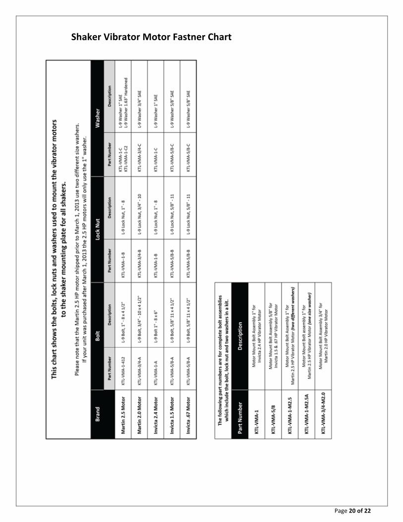
The Bolt Fastening System used to secure the Vibrating Motors to the Motor Mounting Weldment is very important. Various bolts are used corresponding to the size of Vibrator Motor installed. The various bolt sizes are shown in the Parts Breakdown at the end of this manual, as well as the torque values that must be adhered to. It is imperative that all bolts are secured using the specified torque values. Replacement of bolts with non-‐OEM bolts and/or the inappropriate application of torque to the bolts will void the warranty.
All motor mounting bolts are specified by KEMTRON to ensure proper torque. Each bolt is torque to engineered tolerances by KEMTRON prior to shipping. Non-‐OEM replacement bolts are strictly prohibited.
CAUTION If a Vibrator Motor Mounting Bolt becomes loose – NEVER RETIGHTEN – Always replace with a complete bolt assembly.
Mounting Bolts that have loosened, once fully torque, are no longer fit for purpose ad must be replaced.

Page 10 of 22
c. Screens Pretension Screens come in varying sizes to fit individual systems. A detailed list of screens and associated parts can be found under the Screen Parts Breakdown section in this manual. As a standard, a Wedge-‐Block System is employed for retaining the screens on the shaker bed. Alternative methods of screen fastening may be employed, based on customer pref-‐erence. Alternative screen fastening methods are not specifically covered in this manual.
The selection of screens is critical and should reflect the operating conditions. Screens mesh count and screen ratings significantly impact shaker performance. It is important to understand how each screen directly influences the ability of the shaker to achieve solid/liquid separation and consistent conveyance.
Generally, the coarser screens go to rear and lower deck (if there is one) while using progressively finer screens toward the output. When using a dual deck shaker, it is important to understand if the shaker is being used in cascade flow or in parallel flow. Cascade flow typically uses finer screens on the bottom deck and more course screens on the top deck. Dual flow or parallel flow shakers use finer screens on the top deck and more course screens on the bottom deck. Contact KEMTRON Technical Services Team for additional support, if needed.
This is only a guide. Individual experience should guide screen selection for flow rate and solids type to maximize solids removal and discharge dryness. Remember that finer screens wear out faster, especially when subjected to high volumes of solids, such as when drilling very fast.

Page 11 of 22
Generally, a screen one mesh coarser is run on the end of each Shaker to allow discharge to be as dry as possible.
Another important item to understand is that how dry the discharge cuttings do not unilaterally define shaker performance are. A linear motion shaker is designed to provide a clean recoverable fluid. Typically the dryer the solids discharge, the less clean the recovered fluid. A shakers performance is defined by balancing the dryness of the solids discharge with the cleanliness of the recovered fluid.
KEMTRON manufactures a pretensioned polyester powder-‐coated triple layer screen for use in its shakers. Triple layer wire cloth bonded to a stainless steel punch plate attached to a rigid steel frame provides the greatest support for a durable long-‐lasting shaker screen.
The table below illustrates the difference in conductance and micron cut for a few select screen sizes.
Prior to installing the screens always check that the Crown Rubbers are in place and inspect each for wear. There should be at least one Crown Rubber per screen and it fits a metal support running lengthwise down the middle sections of the shaker screen frame. As the Crown Rubber ages, the top will flatten and no longer make the necessary

Page 12 of 22
compressive contact with the installed screens. This will cause excessive vibration and will cause premature screen failure.
Screens should be washed and inspected for damage. Any minor damage can be repaired using KEMTRON Screen Saver Plugs or silicon sealant. Do not attempt to use sealant to prolong the use of the screen. Screen Saver Plugs are available and will seal off any broken cell within the screen.
The rearmost and bottom screens should be installed first. Care must be taken not to damage the polystrips or integral screen seals upon installation.
Once the bottom screen(s) are in place, position the wedge bars and wedges. The wedge bar runs along the entire side length of the screen and provides additional sealing protection. The wedges can be tightened using the supplied Lever Wrench or a small heavy mallet being careful not to damage the screens or the shaker basket.
Figure 9

Page 13 of 22
IMPORTANT Extra care should be taken to ensure the wedges are very tight and secure.
If one of the wedges becomes loose it can severely damage a screen. Not to mention loosing the integrity of the recycled mud and the time it takes to
reinstall it.
The remaining screens can be installed as above.
Wash screens if the drilling mudflow is interrupted for an extended period or at the end of the day. This will prevent the screen from becoming plugged and reducing the screen work area. Some solids can accumulate within the layers of the screen mesh, when the screens are not regularly cleaned. This accumulation can cause excessive weight to be added to a section of the screen, therefore affecting solids conveyance and will result in premature screen failure.
Place screens in their original box for storage and stack them on flat selves. It is also important never to drop screens as the manufacturing process takes advantage of powder coating techniques. The adhesive effects of the powder coat can be detrimentally impacted by dropping the screen.
d. Moving and Start-‐Up Prior to transporting or moving the shaker, it is important to follows these steps:
Remove screens, wedge bars, wedges, and crown rubbers and store it an appropriate place. Lower the shaker deck angle using the jacks on either side of the bed. Secure the shaker bed using the shipping brackets.
Prior to starting-‐up the shaker, it is important to follows these steps:
Reverse the steps above. Ensure that the shaker is in a level plane. Check all bolts are present and secure. Inspect the wiring for worn or damaged insulation. Inspect the crown rubbers for wear. Inspect the screens for damage and the presence of the sealing gasket strips. Inspect for broken springs and worn fabric washers.

Page 14 of 22
3. Maintenance The Linear Motion Shaker requires limited preventative maintenance. However there are a few steps to follow to ensure years of trouble free service.
a. General Complete a common sense inspection of the structure, vibration motors, etc. on a daily basis.
Daily inspect the Screens for wear or holes. Repair or replace as necessary.
b. Lubrication Grease Jack Assembly weekly with a good grade of synthetic lithium base grease using approximately 1-‐2 shots per fitting.
The Vibrator Motors should be greased with MOBIL XHP 222 (for Invicta Motors) or Kluber ISOFLEX TOPAS NB 52 (For Martin Motors) based on the chart below. Do not mix grease types without first checking with supplier to ensure they are compatible. If mixing grease is unavoidable, use only lithium complex alternatives. Ensure that grease nipples are clean to prevent introducing contamination into bearings.
CAUTION Over greasing causes overheating of the bearings and
MUST BE AVOIDED.

Page 15 of 22
RELUBRICATION INTERVAL BASED ON AMBIENT TEMPERATURE FOR INVICTA VIBRATOR MOTORS
ULBK 21 are fitted with shielded ball bearings and are greased for life. ULBK 26 TO 30, remove end covers, circlips and out of balance weights (noting position of weights to keep the same force output on re-assembly). Remove bearing housing with bearing outer race. The inner race remains on the rotor shaft. Provided the bearing and grease are in good condition add new grease by lightly smearing it onto the rollers and re-assemble. ULBK 40 TO 75 have grease nipples fitted as standard. Ensure that they are clean to prevent contamination. Recommended grease is Esso Unirex N3. If mixing of grease is unavoidable use only Lithium complex alternatives. Over greasing causes overheating of the bearings and must be avoided. Grease cavities should never be filled above one third of their capacity and bearing caps should be removed occasionally to clean out excess grease. Old grease should periodically be removed and the bearings cleaned and repacked with new grease. Relubrication intervals are based on continuous operation in ambient temperature up to 20ºC and should be reduced as follows for increases in ambient temperature 25ºC x 0.8, 30ºC x 0.65, 35ºC x 0.5, 40ºC x 0.4. Above 40ºC consult our Technical Department. Data is provided as a guide only and intervals should be shortened/lengthened based on service experience with the particular application. Relube Relube Interval Relube Initial Interval Relube Initial (Hours) Amount Fill (Hours) Amount Fill Type 50 Hz 60 Hz Gms Gms Type 50 Hz 60 Hz Gms Gms ULBK 26-13/2 1700 1400 7 17 ULBK 26-11/6 5800 4800 7 17 ULBK 30-16/2, -20/2 800 700 11 25 ULBK 30-14/6 6000 5000 15 30 ULBK 40-30/2 750 650 15 35 ULBK 30-18/6 6000 5000 15 30 ULBK 40-40/2 700 600 20 55 ULBK 40-27/6 5000 4300 20 40 ULBK 50-50/2 250 200 18 80 ULBK 45-42/6 4800 4100 26 60 ULBK 50-60/6 4200 3800 30 90 ULBK 26-14/4 3900 3300 7 17 ULBK 50-75/6 3800 3400 38 110 ULBK 30-18/4, 25/4 3500 3100 13 30 ULBK60-105/6 3000 2600 54 160 ULBK 40-35/4 3000 2700 18 40 ULBK 75-150/6 2000 1800 66 200 ULBK 45-45/4 2500 2200 22 60 ULBK 50-55/4 2200 1800 30 90 ULBK 30-7.5/8, -
10/8 8000 7000 15 30
ULBK 50-75/4 2000 1600 38 110 ULBK 40-15/8 7000 6500 20 40 ULBK 60-95/4 900 800 47 160 ULBK 45-24/8 6500 6000 26 60 ULBK 50-35/8, -45/8 6000 5500 30 90 ULBK 50-55/8 5500 5000 38 110 ULBK 60-65/8, -90/8 5000 4500 60 160 ULBK 75-150/8 3500 3000 66 200

Page 16 of 22
RELUBRICATION INTERVAL BASED ON AMBIENT TEMPERATURE FOR MARTIN VIBRATOR MOTORS
CAUTION Use only prescribed grease in vibrator motor. If a different grease is used,
vibrator can be damaged and warranty will be voided.
Use only prescribed amount of grease to lubricate vibrator. Too much grease will cause bearings to overheat and result in premature bearing failure.
Lubricate the vibrator with Klüber ISOFLEX TOPAS NB 52 grease from Klüber Lubrication according to Table.
CAUTION For 3,600 rpm machines operating continuously or for long periods of time, reduce lubrication time and amount as
described in step 2. Failure to do so could result in premature bearing failure.
If vibrator housing temperatures exceed 194°F (90°C), cut lubrication time and amount in half for every 18°F (10°C) increment that meets or exceeds 194°F (90°C). Lubricate with Klüber ISOFLEX TOPAS NB 52 grease only. Clean vibrator at each pipe plug in housing to remove dirt and debris. Remove pipe plug. Insert 1/8 in. NPT grease fitting. Add grease. Remove grease fittings; tightly replace pipe plugs. (Use anti-‐seize compound on threads.)
Frame Size
Quantity g
Frequency hrs.
40 12 2000
50 16 2000
60 25 3000
70 40 2000

Page 17 of 22
4. Troubleshooting Below is a table of some possible problems, causes and solutions:
Problem Possible Cause Possible Solution Unable to turn on vibrator motors (No response to the Start Push Buttons)
Generator not running Start Generator
Main CB not ON or tripped Reset Main CB. Turn OFF to reset then ON
Emergency Stop Push Button depressed
Twist the Emergency Stop Button and pull outward
Control CB inside the electrical enclosure tripped
Turn off main CB. Open the door and reset the Control CB by turning off and then on
480 Volts from generator not present
Check for 480 volts at the top of the Main CB. If not there check for broken or loose wires and connections
Check for voltage at the generator-‐See generator service Manual
MCC tripped Reset MCC. Turn knob CCW to off (reset) then CW to on
An open circuit in the wiring (Wires not connected)
Check that the wiring at the bottom of the respective MCC is in the captive screw terminal and secure. Also check wiring at the motor terminal box to be sure the wire-‐nuts are secure
Vibrator Motors starts but trips
A damaged motor
Check motor windings for continuity
The MCC current adjustment is set to low
Readjust the current setting on the affected MCC (Should be set at 8 amps for the shaker motors-‐16 amps for the trash pump motor and 19 to 20 amps for the remaining three pump motors
Shaker running but no linear motion
Vibrator Motors not counter rotating
Switch any two leads of a single motor to get opposite rotation
Page 18 of 22
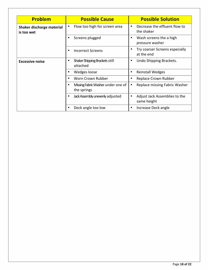
Problem Possible Cause Possible Solution Shaker discharge material is too wet
Flow too high for screen area Decrease the effluent flow to the shaker
Screens plugged Wash screens the a high pressure washer
Incorrect Screens Try coarser Screens especially at the end
Excessive noise Shaker Shipping Brackets still attached
Undo Shipping Brackets.
Wedges loose Reinstall Wedges
Worn Crown Rubber Replace Crown Rubber Missing Fabric Washer under one of the springs
Replace missing Fabric Washer
Jack Assembly unevenly adjusted Adjust Jack Assemblies to the same height
Deck angle too low Increase Deck angle

Page 19 of 22
5. Shaker Parts Breakdown
Page 20 of 22
Shaker Vibrator Motor Fastner Chart

Page 21 of 22
Vibrator Motor Fastening System – Martin Motors

Page 22 of 22
Vibrator Motor Fastening System – Invicta Motors