Linear Cam Trays - Balluffusa.balluff.com/OTPDF/BNS_Accessories.pdf · Linear Cam Trays 11 Linear...
58
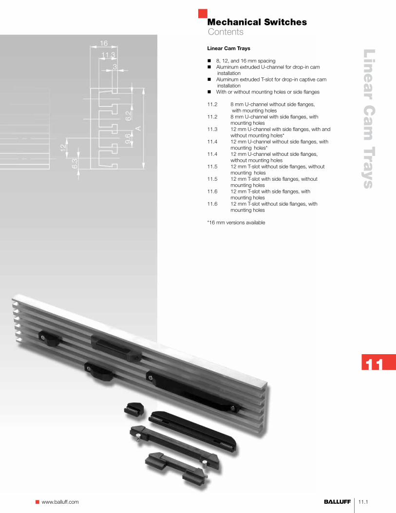
Mechanical Switches 11.1 n www.balluff.com Linear Cam Trays 11 Linear Cam Trays 8, 12, and 16 mm spacing Aluminum extruded U-channel for drop-in cam installation Aluminum extruded T-slot for drop-in captive cam installation With or without mounting holes or side flanges 11.2 8 mm U-channel without side flanges, with mounting holes 11.2 8 mm U-channel with side flanges, with mounting holes 11.3 12 mm U-channel with side flanges, with and without mounting holes* 11.4 12 mm U-channel without side flanges, with mounting holes* 11.4 12 mm U-channel without side flanges, without mounting holes 11.5 12 mm T-slot without side flanges, without mounting holes 11.5 12 mm T-slot with side flanges, without mounting holes 11.6 12 mm T-slot with side flanges, with mounting holes 11.6 12 mm T-slot without side flanges, with mounting holes *16 mm versions available Contents
Transcript of Linear Cam Trays - Balluffusa.balluff.com/OTPDF/BNS_Accessories.pdf · Linear Cam Trays 11 Linear...
Mechanical Switches
11.1n www.balluff.com
Lin
ear C
am
Trays
11
Linear Cam Trays
8, 12, and 16 mm spacing Aluminum extruded U-channel for drop-in cam installation Aluminum extruded T-slot for drop-in captive cam installation With or without mounting holes or side flanges
11.2 8 mm U-channel without side flanges, with mounting holes11.2 8 mm U-channel with side flanges, with mounting holes11.3 12 mm U-channel with side flanges, with and without mounting holes*11.4 12 mm U-channel without side flanges, with mounting holes*11.4 12 mm U-channel without side flanges, without mounting holes11.5 12 mm T-slot without side flanges, without mounting holes11.5 12 mm T-slot with side flanges, without mounting holes11.6 12 mm T-slot with side flanges, with mounting holes11.6 12 mm T-slot without side flanges, with mounting holes
*16 mm versions available
Contents
Mechanical Switches
11.2
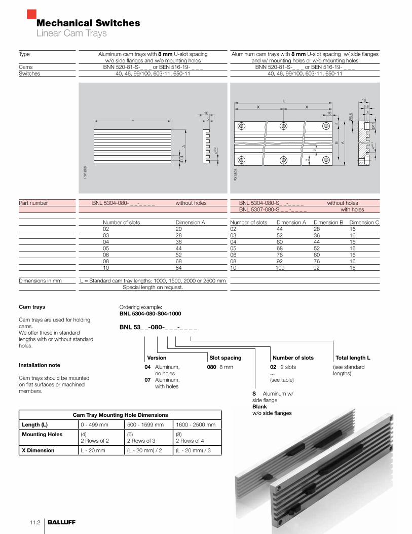
Aluminum cam trays with 8 mm U-slot spacingw/o side flanges and w/o mounting holes
BNN 520-81-S-_ _ _ or BEN 516-19- _ _ _40, 46, 99/100, 603-11, 650-11
BNL 5304-080- _ _-_ _ _ _ without holes
Number of slots Dimension A 02 20 03 28 04 36 05 44 06 52 08 68 10 84
L = Standard cam tray lengths: 1000, 1500, 2000 or 2500 mmSpecial length on request.
Type
Cams Switches
Part number
Dimensions in mm
Aluminum cam trays with 8 mm U-slot spacing w/ side flanges and w/ mounting holes or w/o mounting holes
BNN 520-81-S-_ _ _ or BEN 516-19- _ _ _40, 46, 99/100, 603-11, 650-11
BNL 5304-080-S_ _-_ _ _ _ without holes BNL 5307-080-S _ _ -_ _ _ _ with holes
Number of slots Dimension A Dimension B Dimension C 02 44 28 1603 52 36 1604 60 44 1605 68 52 1606 76 60 1608 92 76 1610 109 92 16
Slot spacing
02 2 slots ... (see table)
Number of slots
04 Aluminum, no holes 07 Aluminum, with holes
080 8 mm
Version
Cam trays
Cam trays are used for holding cams. We offer these in standard lengths with or without standard holes.
Installation note
Cam trays should be mounted on flat surfaces or machined members.
X X
Ordering example:BNL 5304-080-S04-1000
BNL 53_ _-080-_ _ _-_ _ _ _
(see standard lengths)
Total length L
S Aluminum w/ side flange Blank w/o side flangesCam Tray Mounting Hole Dimensions
Length (L) 0 - 499 mm 500 - 1599 mm 1600 - 2500 mm
Mounting Holes (4)2 Rows of 2
(6)2 Rows of 3
(8)2 Rows of 4
X Dimension L - 20 mm (L - 20 mm) / 2 (L - 20 mm) / 3
Linear Cam Trays

Mechanical Switches
11.3n www.balluff.com
Lin
ear C
am
Trays
11
Aluminum cam trays with 12 mm U-slot spacingw/ side flanges and w/o mounting holes
BNN 520-UA/UB-_ _ _ or BEN 516-14- _ _ _61, 62, 72, 100, 602-11, 605-11, 610-11, 611-11, 612-11, 613-11
BNL 5304-120-S_ _-_ _ _ _ without holes
Number of slots Dimension A 02 50 03 62 04 74 05 86 06 98 08 122
L = Standard cam tray lengths: 1000, 1500, 2000 or 2500 mmSpecial length on request.
Aluminum cam trays with 12 mm U-slot spacingw/side flanges and w/ mounting holes
BNN 520-UA/UB-_ _ _ or BEN 516-14- _ _ _61, 62, 72, 100, 602-11, 605-11, 610-11, 611-11, 612-11, 613-11
BNL 5307-120-S_ _-_ _ _ _ with holes
Number of slots Dimension A Dimension B Dimension C 02 50 34 1603 62 46 1604 74 58 1605 86 70 1606 98 82 1608 122 106 16
X X
Slot spacing02 2 slots ... (see table)
Number of slots
04 Aluminum, no holes 07 Aluminum, with holes
120 12 mm
Version
Ordering example:BNL 5304-120-S04-1000
BNL 53_ _-120-S_ _-_ _ _ _
Total Length L(see standard lengths)
Cam Tray Mounting Hole Dimensions
Length (L) 0 - 499 mm 500 - 1599 mm 1600 - 2500 mm
Mounting Holes (4)2 Rows of 2
(6)2 Rows of 3
(8)2 Rows of 4
X Dimension L - 20 mm (L - 20 mm) / 2 (L - 20 mm) / 3
Linear Cam Trays

Mechanical Switches
11.4
Aluminum cam trays with 12 mm U-slot spacingw/o side flanges and w/o mounting holes
BNN 520-UA/UB-_ _ _ or BEN 516-14- _ _ _61, 62, 72, 100, 602-11, 605-11, 610-11, 611-11, 612-11, 613-11
BNL 5304-120-_ _-_ _ _ _ without holes
Number of slots Dimension A 12 mm 16 mm 01 17 02 29 41 03 41.5 57 04 53 73 06 77 105 08 101 137 10 125
L = Standard cam tray lengths: 1000, 1500, 2000 or 2500 mmSpecial length on request
Type
Cams Switches
Part number
Dimensions in mm
Cam trays
Cam trays are used for holding cams. We offer these in standard lengths with or without standard holes.
Installation note
Cam trays should be mounted on flat surfaces or machined members.
Aluminum cam trays with 12 mm U-slot spacingw/o side flanges and w/ mounting holes
BNN 520-UA/UB_ _ _ _ or BEN 516-14-_ _ _ _61, 62, 72, 100, 602-11, 605-11, 610-11, 611-11, 612-11, 613-11
BNL 5307-120-_ _-_ _ _ _ with holes
Number Dimension A Dimension B Dimension Cof slots 12 mm 16 mm 12 mm 16 mm 12 mm 16 mm01 17 8.502 29 41 14.4 20.503 41.5 57 20.8 28.504 53 73 26.5 36.506 77 105 8.5 12.5 60 8008 101 137 8.5 12.5 84 11210 125 8.5 108
04 Aluminum, no holes 07 Aluminum, with holes
Slot spacing
02 2 slots ... (see table)
Number of slots
120 12 mm 160 16 mm
Version
Ordering example:BNL 5304-120-04-1000
BNL 53_ _-_ _ _-_ _-_ _ _ _
(see standard lengths)
Total length L
X X
Cam Tray Mounting Hole Dimensions
Length (L) 0 - 499 mm 500 - 1599 mm 1600 - 2500 mm
Mounting Holes* 1, 2, 3 & 4 Channels
(2)1 Row of 2
(3)1 Row of 3
(4)1 Row of 4
Mounting Holes6, 8 & 10 Channels
(4)2 Rows of 2
(6)2 Rows of 3
(8)2 Rows of 4
X Dimension L - 20 mm (L - 20 mm) / 2 (L - 20 mm) / 3
*Mounting holes in center of tray
Linear Cam Trays
Mechanical Switches
11.5n www.balluff.com
Lin
ear C
am
Trays
11
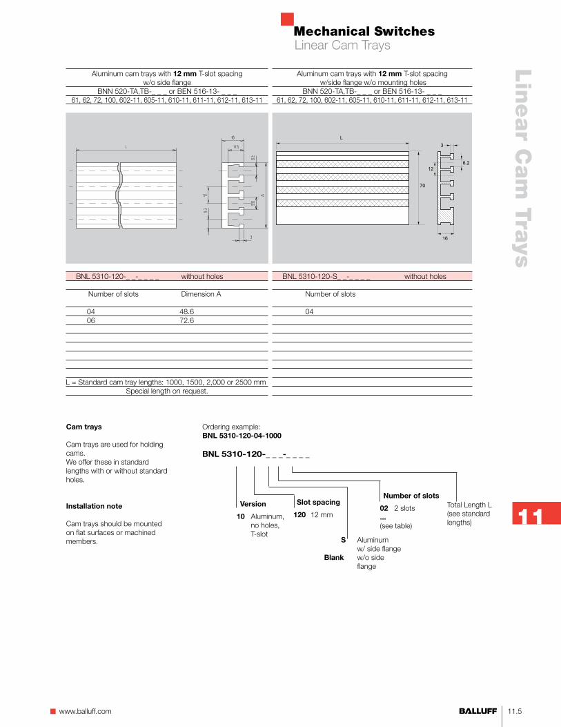
Aluminum cam trays with 12 mm T-slot spacingw/o side flange
BNN 520-TA,TB-_ _ _ or BEN 516-13- _ _ _61, 62, 72, 100, 602-11, 605-11, 610-11, 611-11, 612-11, 613-11
BNL 5310-120-_ _-_ _ _ _ without holes
Number of slots Dimension A
04 48.6 06 72.6
L = Standard cam tray lengths: 1000, 1500, 2,000 or 2500 mmSpecial length on request.
Aluminum cam trays with 12 mm T-slot spacing w/side flange w/o mounting holes
BNN 520-TA,TB-_ _ _ or BEN 516-13- _ _ _61, 62, 72, 100, 602-11, 605-11, 610-11, 611-11, 612-11, 613-11
BNL 5310-120-S_ _-_ _ _ _ without holes
Number of slots 04
Cam trays
Cam trays are used for holding cams. We offer these in standard lengths with or without standard holes.
Installation note
Cam trays should be mounted on flat surfaces or machined members.
Slot spacing02 2 slots ... (see table)
Number of slots
10 Aluminum, no holes, T-slot
120 12 mm Version
Ordering example:BNL 5310-120-04-1000
BNL 5310-120-_ _ _-_ _ _ _
Total Length L(see standard lengths)
S Aluminum w/ side flangeBlank w/o side flange
Linear Cam Trays

Mechanical Switches
11.6
Aluminum cam trays with 12 mm T-slot spacingw/o side flange w/ mounting holes
BEN 516-11-100061, 62, 72, 100, 602-11, 605-11, 610-11, 611-11, 612-11, 613-11
BNL 5315-120-_ _-2500 with holes
Number of slots Dimension Dimension Dimension Dimension A B C D04 53.8 36 125 45006 77.8 36 125 45008 101.8 60 125 450
Standard cam tray length = 2500 mm
Aluminum cam trays with 12 mm T-slot spacingw/ side flange and w/ mounting holes
BNN 520-TA,TB-_ _ _ or BEN 516-13- _ _ _61, 62, 72, 100, 602-11, 605-11, 610-11, 611-11, 612-11, 613-11
BNL 5311-120-S04-_ _ _ _ with holes Number of slots 04
L = Standard cam tray lengths: 1000, 1500, 2000 or 2500 mm
Special length on request.
Type
Cams Switch
Part number
Dimensions in mm
Cam trays
Cam trays are used for holding cams. We offer these in standard lengths with or without standard holes.
Installation note
Cam trays should be mounted on flat surfaces or machined members.
Slot spacing
04 4 slots
Number of slots
11 Aluminum w/ side flange w/ mounting holes 15 Aluminum w/o flange w/ mounting holes
120 12 mm
Version
Ordering example:BNL 5311-120-04-1000
BNL 53_ _-_ _ _-_ _-_ _ _ _
(see standard lengths)
Total length L
Cam Tray Mounting Hole Dimensions
Length (L) 0 - 499 mm 500 - 1500 mm 1600 - 2500 mm
Mounting Holes (2)1 Row of 2
(3)1 Row of 3
(4)1 Row of 4
X Dimension L - 20 mm (L - 20 mm) / 2 (L - 20 mm) / 3
Linear Cam Trays
C D
2500
D C
BA
Ø4.3 Ø7.4
8.3
66
6
16
11.5

Mechanical Switches
12.1n www.balluff.com
Rota
ry Cam
Dru
ms &
Trays
12
Rotary Cam Drums and Trays
12 and 16 mm spacing Rotary cam drums are machined solid aluminum Rotary cam drums are extruded aluminum rolled into a semi-circle U-channel for drop-in installation T-slot for drop-in captive cam installation
12.2 12 mm U-channel rotary drums*12.3 12 mm T-slot rotary drums*12.4 12 mm T-slot rotary cam trays
*16 mm versions available
Contents
Mechanical Switches
12.2
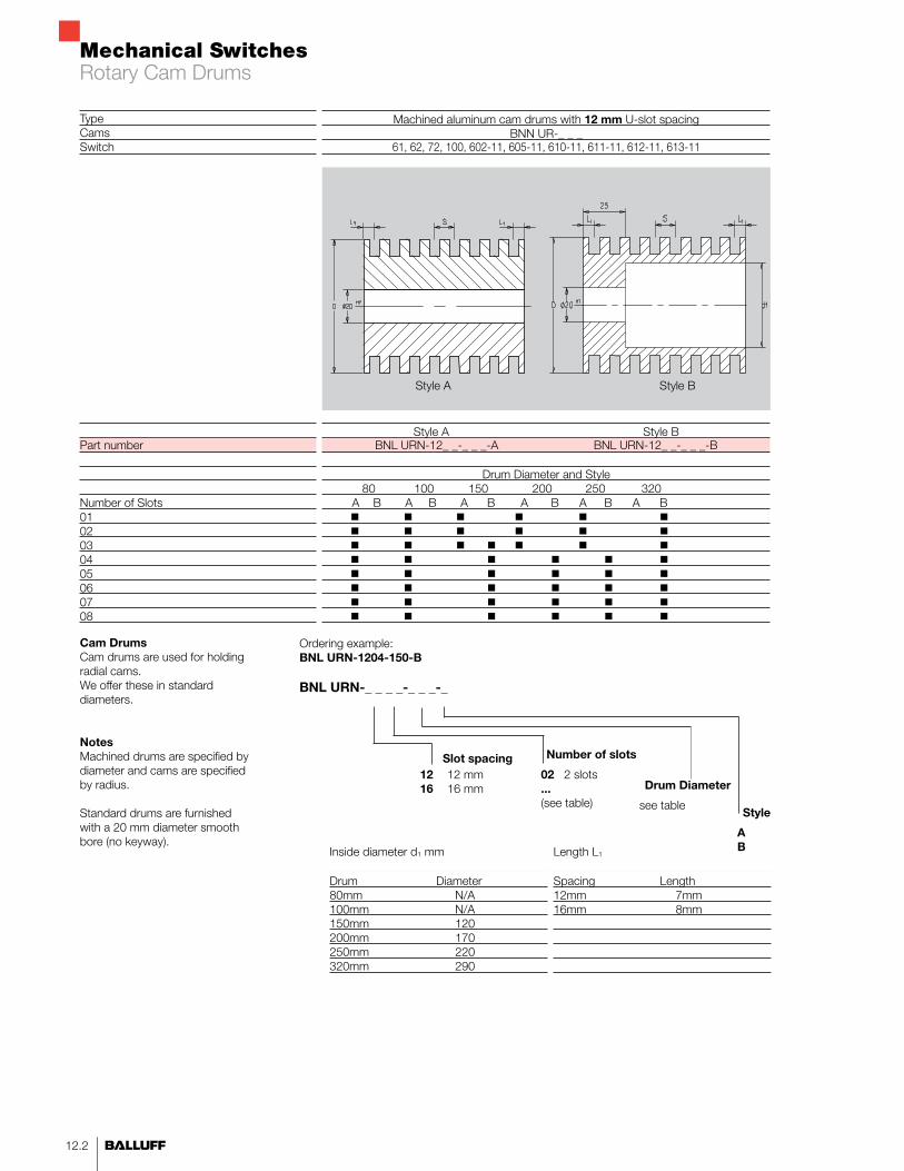
Machined aluminum cam drums with 12 mm U-slot spacingBNN UR-_ _ _
61, 62, 72, 100, 602-11, 605-11, 610-11, 611-11, 612-11, 613-11
Style A Style BBNL URN-12_ _-_ _ _-A BNL URN-12_ _-_ _ _-B
Drum Diameter and Style 80 100 150 200 250 320 A B A B A B A B A B A BB
TypeCamsSwitch
Part number
Number of Slots0102030405060708
Cam DrumsCam drums are used for holding radial cams. We offer these in standard diameters.
NotesMachined drums are specified by diameter and cams are specified by radius.
Standard drums are furnished with a 20 mm diameter smooth bore (no keyway).
02 2 slots ... (see table)
Number of slots
12 12 mm16 16 mm
Ordering example:BNL URN-1204-150-B
BNL URN-_ _ _ _-_ _ _-_
AB
Style
Slot spacing
see table
Drum Diameter
Inside diameter d1 mm
Drum Diameter80mm N/A100mm N/A150mm 120200mm 170250mm 220320mm 290
Length L1
Spacing Length12mm 7mm16mm 8mm
Style A Style B
Rotary Cam Drums
Mechanical Switches
12.3n www.balluff.com
Rota
ry Cam
Dru
ms &
Trays
12
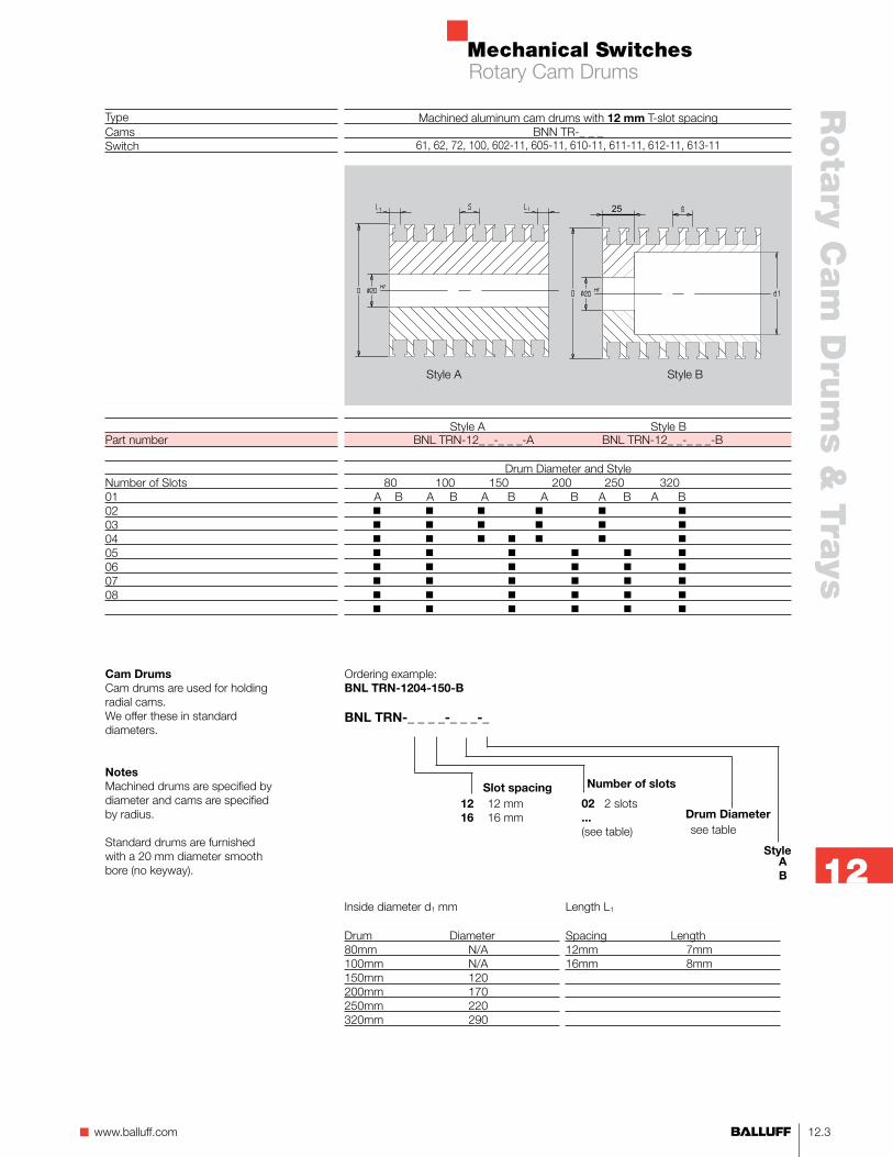
TypeCamsSwitch
Part number
Number of Slots0102030405060708
02 2 slots ... (see table)
Number of slots
12 12 mm16 16 mm
Cam DrumsCam drums are used for holding radial cams. We offer these in standard diameters.
NotesMachined drums are specified by diameter and cams are specified by radius.
Standard drums are furnished with a 20 mm diameter smooth bore (no keyway).
Ordering example:BNL TRN-1204-150-B
BNL TRN-_ _ _ _-_ _ _-_
A B
Slot spacing
see tableDrum Diameter
Style
Inside diameter d1 mm
Drum Diameter80mm N/A100mm N/A150mm 120200mm 170250mm 220320mm 290
Length L1
Spacing Length12mm 7mm16mm 8mm
Machined aluminum cam drums with 12 mm T-slot spacingBNN TR-_ _ _
61, 62, 72, 100, 602-11, 605-11, 610-11, 611-11, 612-11, 613-11
Style A Style BBNL TRN-12_ _-_ _ _-A BNL TRN-12_ _-_ _ _-B
Drum Diameter and Style 80 100 150 200 250 320 A B A B A B A B A B A BB
25
Style A Style B
Rotary Cam Drums
Mechanical Switches
12.4
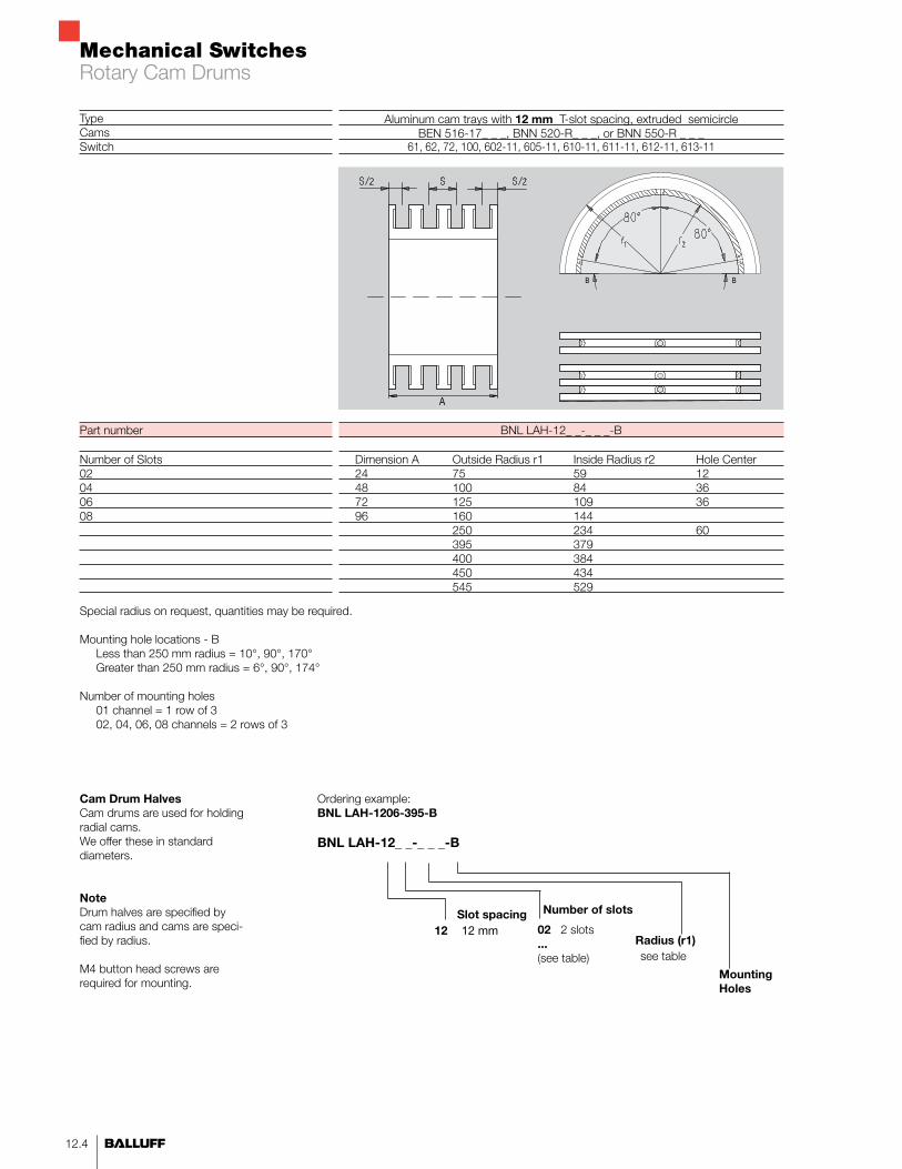
Aluminum cam trays with 12 mm T-slot spacing, extruded semicircleBEN 516-17_ _ _, BNN 520-R_ _ _, or BNN 550-R _ _ _
61, 62, 72, 100, 602-11, 605-11, 610-11, 611-11, 612-11, 613-11
BNL LAH-12_ _-_ _ _-B
Dimension A Outside Radius r1 Inside Radius r2 Hole Center 24 75 59 12 48 100 84 36 72 125 109 36 96 160 144 250 234 60 395 379 400 384 450 434 545 529
Cam Drum HalvesCam drums are used for holding radial cams. We offer these in standard diameters.
NoteDrum halves are specified by cam radius and cams are speci-fied by radius.
M4 button head screws are required for mounting.
02 2 slots ... (see table)
Number of slots
12 12 mm
Ordering example:BNL LAH-1206-395-B
BNL LAH-12_ _-_ _ _-B
Slot spacing
see tableRadius (r1)
Mounting Holes
Special radius on request, quantities may be required.
Mounting hole locations - B Less than 250 mm radius = 10°, 90°, 170° Greater than 250 mm radius = 6°, 90°, 174°
Number of mounting holes 01 channel = 1 row of 3 02, 04, 06, 08 channels = 2 rows of 3
TypeCamsSwitch
Part number
Number of Slots02040608
A
BB
Rotary Cam Drums

Mechanical Switches
13.1n www.balluff.com
Lin
ear Trip
Cam
s
13
Linear Trip Cams
Mechanical contact or inductive non-contact U-channel mounts by friction wedges for drop-in cam installation T-slot mounts by T-nuts or pressure plates for drop-in captive installation Single piece with single set screw for very short lengths Single piece with two set screws for intermediate lengths Modular U-channel or T-slot end ramps for longer custom lengths
13.2 8 mm U-channel mechanical13.3 12 mm U-channel mechanical13.4 12 mm T-slot mechanical13.5 12 mm U-channel or T-slot modular mechanical13.6 12 mm U-channel mechanical precision13.7 12 mm T-slot modular inductive13.9 8 mm U-channel inductive13.9 12 mm T-slot inductive13.9 12 mm U-channel inductive
Contents

Mechanical Switches
13.2
TypeCamsSwitch
Form A - Single set screwPart number
Form B - Twin set screwPart number
L0
6.510
L20253040486080100145200250440
BNN 520-81-S-0BNN 520-81-S-6.5BNN 520-81-S-10
BNN 520-81-S-20BNN 520-81-S-25BNN 520-81-S-30BNN 520-81-S-40BNN 520-81-S-48BNN 520-81-S-60BNN 520-81-S-80BNN 520-81-S-100BNN 520-81-S-145BNN 520-81-S-200BNN 520-81-S-250BNN 520-81-S-440
BNN 520-81-S-_ _ _BNL 5304-080-... or BNL 5307-080 U-slot cam trays
40, 46, 99/100
B1818
21.5
B36414656647696116161216266416
8 mm spacing
Ordering example:BNN 520-81-S-25
BNL 520-81-S-_ _ _
U channelActuation LengthSee Table
Form A
Form B
Dimensions in mm
L = Length of switching surface. Additional lengths on request. Quantities may be required.
Material:Steel with hardened and burnished surface. HRC 61+2
Installation:As the screw is tightened, the lower portion of the cam spreads apart holding the cam firmly in place.
Replacement Set Screw:GEW-STIFT M6x14-701533
Note!Cams used in safety applications must be per-manently secured to the cam tray.
Linear Cams Mechanical Cams
Mechanical Switches
13.3n www.balluff.com
Lin
ear Trip
Cam
s
13
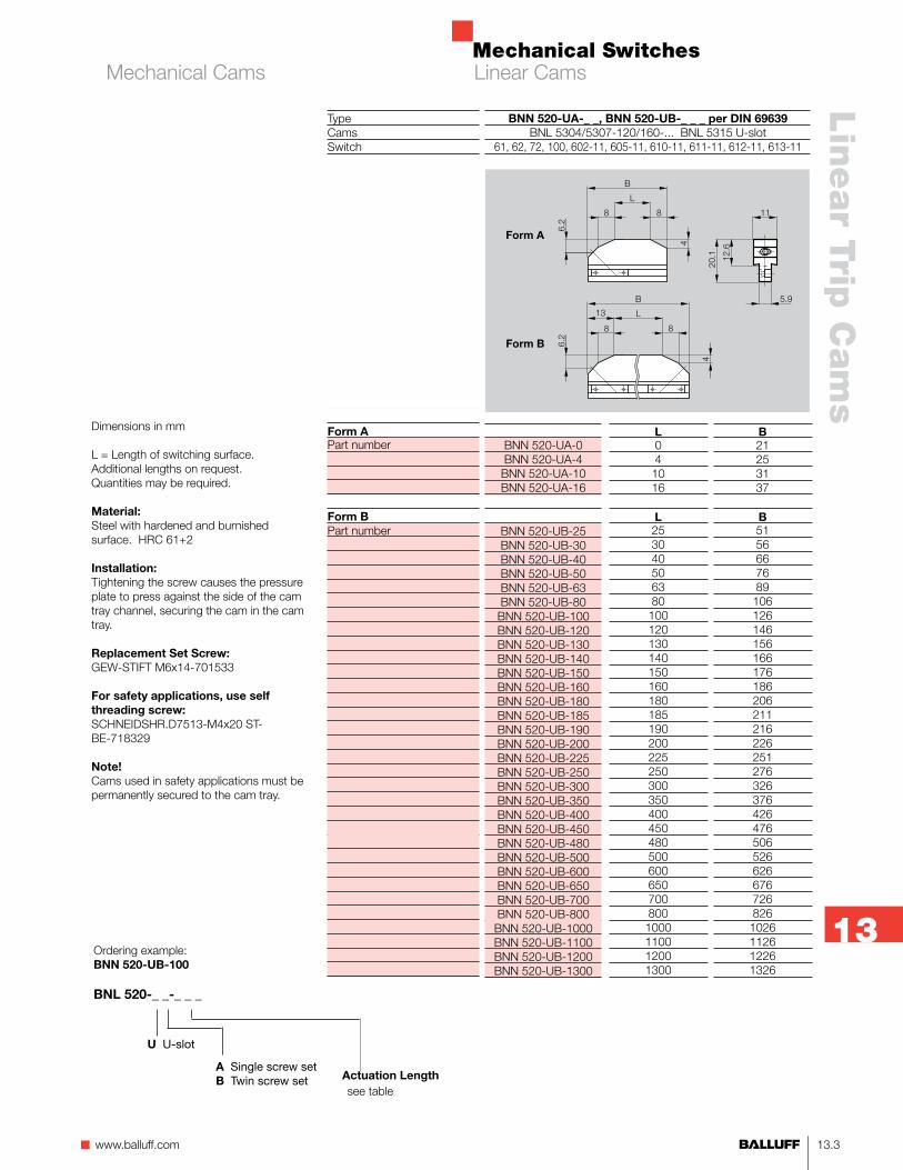
Dimensions in mm
L = Length of switching surface. Additional lengths on request. Quantities may be required.
Material:Steel with hardened and burnished surface. HRC 61+2
Installation:Tightening the screw causes the pressure plate to press against the side of the cam tray channel, securing the cam in the cam tray.
Replacement Set Screw:GEW-STIFT M6x14-701533
For safety applications, use self threading screw:SCHNEIDSHR.D7513-M4x20 ST-BE-718329
Note!Cams used in safety applications must be permanently secured to the cam tray.
BNN 520-UA-0 BNN 520-UA-4 BNN 520-UA-10 BNN 520-UA-16
BNN 520-UB-25 BNN 520-UB-30BNN 520-UB-40 BNN 520-UB-50BNN 520-UB-63 BNN 520-UB-80BNN 520-UB-100 BNN 520-UB-120 BNN 520-UB-130BNN 520-UB-140BNN 520-UB-150 BNN 520-UB-160BNN 520-UB-180BNN 520-UB-185BNN 520-UB-190BNN 520-UB-200 BNN 520-UB-225BNN 520-UB-250 BNN 520-UB-300 BNN 520-UB-350BNN 520-UB-400BNN 520-UB-450BNN 520-UB-480BNN 520-UB-500BNN 520-UB-600BNN 520-UB-650BNN 520-UB-700BNN 520-UB-800BNN 520-UB-1000BNN 520-UB-1100BNN 520-UB-1200BNN 520-UB-1300
L041016
L2530405063801001201301401501601801851902002252503003504004504805006006507008001000110012001300
B21253137
B51566676891061261461561661761862062112162262512763263764264765065266266767268261026112612261326
BNN 520-UA-_ _, BNN 520-UB-_ _ _ per DIN 69639BNL 5304/5307-120/160-... BNL 5315 U-slot
61, 62, 72, 100, 602-11, 605-11, 610-11, 611-11, 612-11, 613-11
Form A
Form B
Ordering example:BNN 520-UB-100
BNL 520-_ _-_ _ _
see tableActuation Length
U U-slot
A Single screw setB Twin screw set
TypeCamsSwitch
Form APart number
Form BPart number
Linear CamsMechanical Cams
Mechanical Switches
13.4
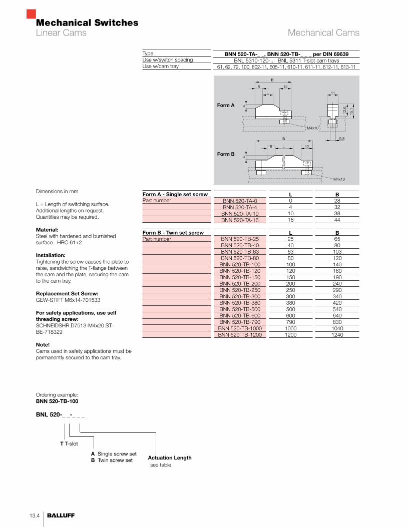
B28323844
B658010312014016019024029034042054064083010401240
BNN 520-TA-0BNN 520-TA-4BNN 520-TA-10BNN 520-TA-16
BNN 520-TB-25 BNN 520-TB-40BNN 520-TB-63BNN 520-TB-80BNN 520-TB-100BNN 520-TB-120BNN 520-TB-150BNN 520-TB-200BNN 520-TB-250BNN 520-TB-300BNN 520-TB-380BNN 520-TB-500BNN 520-TB-600BNN 520-TB-790BNN 520-TB-1000BNN 520-TB-1200
BNN 520-TA-_ _, BNN 520-TB-_ _ _ per DIN 69639BNL 5310-120-... BNL 5311 T-slot cam trays
61, 62, 72, 100, 602-11, 605-11, 610-11, 611-11, 612-11, 613-11
L041016
L2540638010012015020025030038050060079010001200
Form A
Form B
TypeUse w/switch spacing Use w/cam tray
Form A - Single set screwPart number
Form B - Twin set screwPart number
Ordering example:BNN 520-TB-100
BNL 520-_ _-_ _ _
see tableActuation Length
T T-slot
A Single screw setB Twin screw set
Dimensions in mm
L = Length of switching surface. Additional lengths on request. Quantities may be required.
Material:Steel with hardened and burnished surface. HRC 61+2
Installation:Tightening the screw causes the plate to raise, sandwiching the T-flange between the cam and the plate, securing the cam to the cam tray.
Replacement Set Screw:GEW-STIFT M6x14-701533
For safety applications, use self threading screw:SCHNEIDSHR.D7513-M4x20 ST-BE-718329
Note!Cams used in safety applications must be permanently secured to the cam tray.
Linear Cams Mechanical Cams
Mechanical Switches
13.5n www.balluff.com
Lin
ear Trip
Cam
s
13
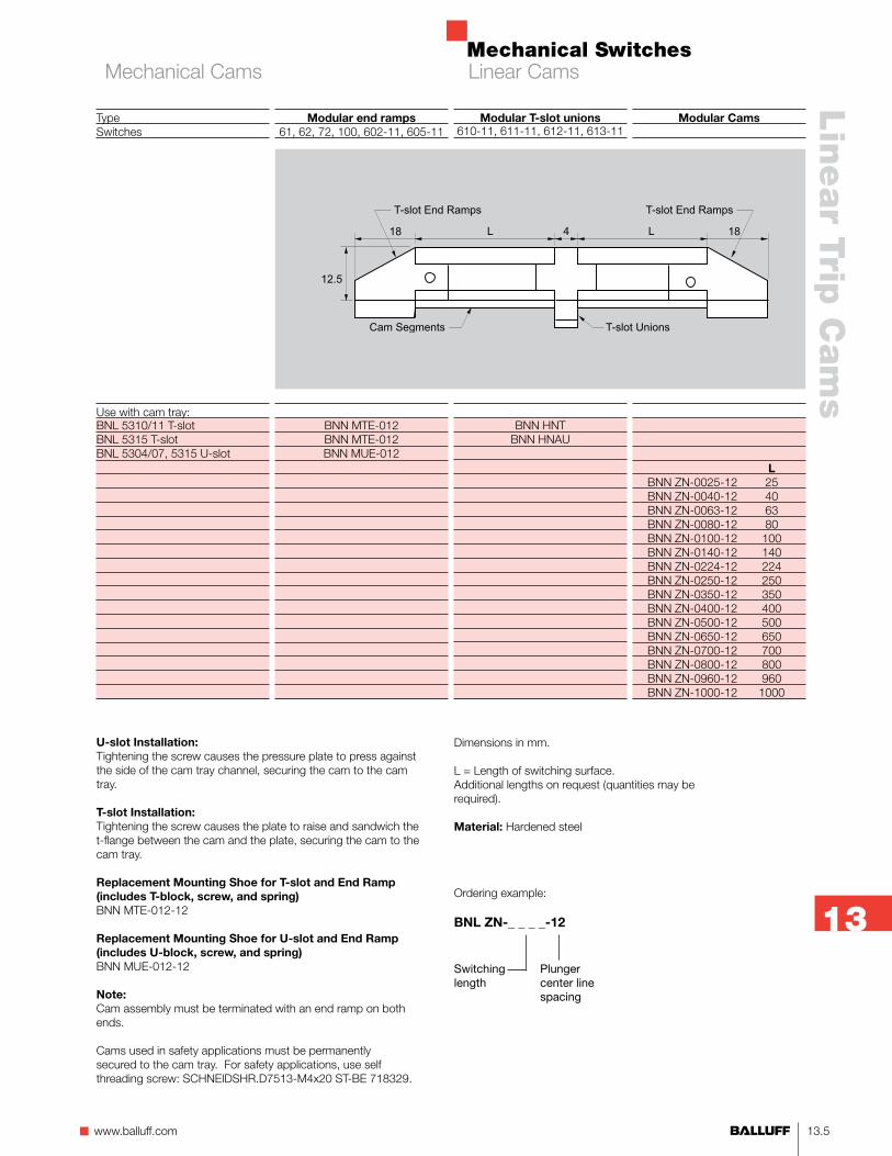
Modular Cams
LBNN ZN-0025-12 25BNN ZN-0040-12 40BNN ZN-0063-12 63BNN ZN-0080-12 80BNN ZN-0100-12 100BNN ZN-0140-12 140BNN ZN-0224-12 224BNN ZN-0250-12 250BNN ZN-0350-12 350BNN ZN-0400-12 400BNN ZN-0500-12 500BNN ZN-0650-12 650BNN ZN-0700-12 700BNN ZN-0800-12 800BNN ZN-0960-12 960BNN ZN-1000-12 1000
Modular end ramps61, 62, 72, 100, 602-11, 605-11
BNN MTE-012BNN MTE-012BNN MUE-012
Modular T-slot unions610-11, 611-11, 612-11, 613-11
BNN HNTBNN HNAU
TypeSwitches
Use with cam tray:BNL 5310/11 T-slotBNL 5315 T-slotBNL 5304/07, 5315 U-slot
U-slot Installation:Tightening the screw causes the pressure plate to press against the side of the cam tray channel, securing the cam to the cam tray.
T-slot Installation:Tightening the screw causes the plate to raise and sandwich the t-flange between the cam and the plate, securing the cam to the cam tray.
Replacement Mounting Shoe for T-slot and End Ramp (includes T-block, screw, and spring)BNN MTE-012-12
Replacement Mounting Shoe for U-slot and End Ramp(includes U-block, screw, and spring)BNN MUE-012-12
Note:Cam assembly must be terminated with an end ramp on both ends.
Cams used in safety applications must be permanently secured to the cam tray. For safety applications, use self threading screw: SCHNEIDSHR.D7513-M4x20 ST-BE 718329.
Dimensions in mm.
L = Length of switching surface.Additional lengths on request (quantities may be required).
Material: Hardened steel
Ordering example:
BNL ZN-_ _ _ _-12
Switching length
Plunger center line spacing
Linear CamsMechanical Cams

Mechanical Switches
13.6
Precision adjustment camBNL 5304/5307-120/160, 5315
61, 62, 72, 100
BNN 520-X-041
Precision adjustment cam BNL 5304/5307-120/160, 5315
61, 62, 72, 100
BNN 520-120-V
Linear cam with precision adjustment with 2.5 mm diameter pin (not included). Maximum adjustment on both sides is 5.5 mm (11 mm total). Scale has 25 graduations (1 grad = .02 mm). Use with 12 mm and 16 mm switch spacing.
TypeCam traysSwitches
Part number
Linear cam with precision adjustment with hex wrench (not included). Maximum adjustment on both sides is 2 mm (4 mm total).
Use with 12 mm and 16 mm switch spacing.
Linear Cams Precision Mechanical Cams

Mechanical Switches
13.7n www.balluff.com
Lin
ear Trip
Cam
s
13
TypeCam traySwitches
Non-contact Inductive CamPart Number
Non-contact Linear End Ramp(two required for segment)Part Number
Installation:BEN516-11Insert end ramps into each end of linear cam. Position cam segment into BNL 5315 cam. As the set screw is tightened, the threads will grip into the T-slot side flange.
Cams are available only in one meter pieces. Cams can be cut for applications less than one meter (add 12.5 mm for each end ramp for total length).
Cams can be installed end-to-end for applications longer than one meter (add 12.5 mm for each end ramp for total length).
Notes:Cams used in safety applications must be permanently secured to the cam tray.
BEN style cams are intended for non-contact operations or inductive sensors only. Misapplication for use as trip cams for mechanical limit switches will result in extremely rapid wear and failure.
BEN 516-11BNL 5315
602-11, 605-11, 610-11, 611-11, 612-11, 613-11
BEN 516-11-1000
BEN 516-16-12.5-00
Non-contact Cam End Ramp
Non-contact Inductive Cam
BNL 5315 Cam Tray
Linear CamsInductive Cams
Mechanical Switches
13.8
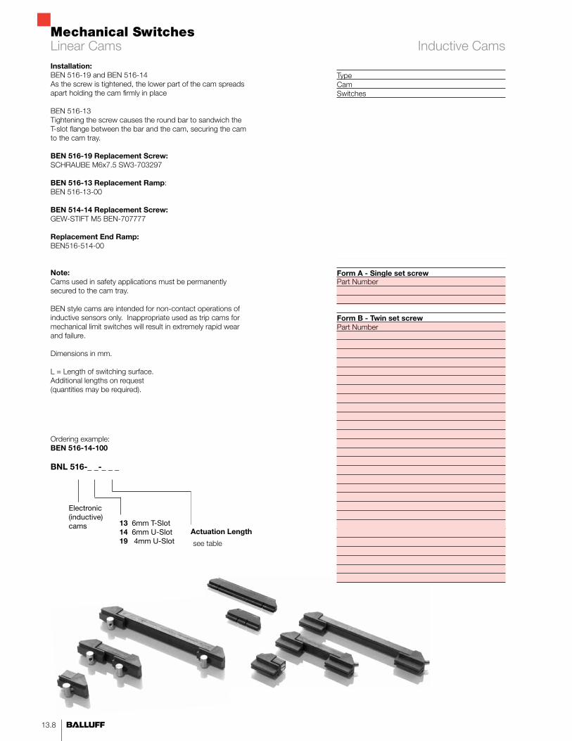
Inductive Cams
TypeCamSwitches
Form A - Single set screwPart Number
Form B - Twin set screwPart Number
Installation:BEN 516-19 and BEN 516-14As the screw is tightened, the lower part of the cam spreads apart holding the cam firmly in place
BEN 516-13Tightening the screw causes the round bar to sandwich the T-slot flange between the bar and the cam, securing the cam to the cam tray.
BEN 516-19 Replacement Screw:SCHRAUBE M6x7.5 SW3-703297
BEN 516-13 Replacement Ramp: BEN 516-13-00
BEN 514-14 Replacement Screw:GEW-STIFT M5 BEN-707777
Replacement End Ramp:BEN516-514-00
Note:Cams used in safety applications must be permanently secured to the cam tray.
BEN style cams are intended for non-contact operations of inductive sensors only. Inappropriate used as trip cams for mechanical limit switches will result in extremely rapid wear and failure.
Dimensions in mm.
L = Length of switching surface.Additional lengths on request (quantities may be required).
Ordering example:BEN 516-14-100
BNL 516-_ _-_ _ _
Actuation Length
Electronic (inductive) cams 13 6mm T-Slot
14 6mm U-Slot19 4mm U-Slot see table
Linear Cams
Mechanical Switches
13.9n www.balluff.com
Lin
ear Trip
Cam
s
13
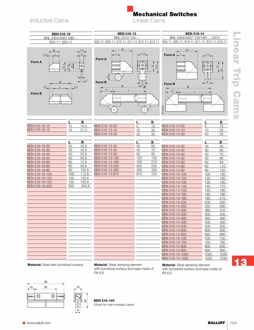
L B0 1510 2520 35
L B25 5530 6040 7050 8063 9380 11090 120100 130120 150130 160140 170150 180160 190180 210200 230250 280280 310300 330360 390400 430500 530600 630650 680700 730750 780800 830900 9301000 10301200 1230
BEN 516-14-00BEN 516-14-10BEN 516-14-20
BEN 516-14-25 BEN 516-14-30BEN 516-14-40BEN 516-14-50BEN 516-14-63BEN 516-14-80BEN 516-14-90BEN 516-14-100BEN 516-14-120BEN 516-14-130BEN 516-14-140BEN 516-14-150BEN 516-14-160BEN 516-14-180BEN 516-14-200BEN 516-14-250BEN 516-14-280BEN 516-14-300BEN 516-14-360BEN 516-14-400BEN 516-14-500BEN 516-14-600BEN 516-14-650BEN 516-14-700BEN 516-14-750BEN 516-14-800BEN 516-14-900BEN 516-14-1000BEN 516-14-1200
L B0 1510 2520 35
L B30 6040 7050 80100 130180 210200 230300 330675 705
BEN 516-13-00BEN 516-13-10BEN 516-13-20
BEN 516-13-30BEN 516-13-40BEN 516-13-50BEN 516-13-100BEN 516-13-180BEN 516-13-200BEN 516-13-300BEN 516-13-675
BEN 516-13BNL 5310-120-...
602-11, 605-11, 610-11, 611-11, 612-11, 613-11
Material: Steel damping element with burnished surface and base made of PA 6.6.
BEN 516-14BNL 5304/5307-120/160-..., 5315
602-11, 605-11, 610-11, 611-11, 612-11, 613-11
Form A
Form B
Form A
Form B
Material: Steel damping element with burnished surface and base made of PA 6.6.
BEN 516-19-10BEN 516-19-15
BEN 516-19-20BEN 516-19-30BEN 516-19-40BEN 516-19-50BEN 516-19-60BEN 516-19-80BEN 516-19-90BEN 516-19-100BEN 516-19-120BEN 516-19-150BEN 516-19-250
BEN 516-19BNL 5304/5307-080-...
603-11, 650-11
Material: Steel with burnished surface.
Form A
Form B
L B10 16.315 21.3
L B20 32.630 42.640 52.650 62.660 72.680 92.690 102.6100 112.6120 132.6150 162.6250 262.6
Linear CamsInductive Cams
10 30
50
10
20
6
BEN 516-14VUnion for non-contact cams
Mechanical Switches
13.10

Mechanical Switches
14.1n www.balluff.com
Radia
l Trip C
am
s
14
Radial Trip Cams
Mechanical contact or inductive non-contact U-channel mount by friction wedges for drop-in cam installation T-slot mount by T-nuts or pressure plates for drop-in captive installation Two piece with single set screw for small angles Three piece with two set screws for larger angles
14.2 12 mm U-channel mechanical14.4 12 mm T-slot mechanical14.6 12 mm T-slot inductive14.8 12 mm U-channel segmented mechanical cam kits for robot zone limit systems14.10 12 mm T-slot segmented inductive cam kits for robot zone limit systems
Contents

Mechanical Switches
14.2
Total angle(°)4652577287116131156
3742496378104119134224
263038607590105120150210
1922273756678297112127144202
S Arc length(mm)
410142841556983
410163349658298196
41023466992114137184274
41020295688118147177206236354
Style
11111222
111112222
1112222222
111222222222
Part number
BNN UR-004-040-12CBNN UR-010-040-12CBNN UR-015-040-12CBNN UR-030-040-12CBNN UR-045-040-12CBNN UR-060-040-12CBNN UR-075-040-12CBNN UR-090-040-12C
BNN UR-004-050-12CBNN UR-009-050-12CBNN UR-015-050-12CBNN UR-030-050-12CBNN UR-045-050-12CBNN UR-060-050-12CBNN UR-075-050-12CBNN UR-090-050-12CBNN UR-180-050-12C
BNN UR-003-075-12CBNN UR-007-075-12CBNN UR-015-075-12CBNN UR-030-075-12CBNN UR-045-075-12CBNN UR-060-075-12CBNN UR-075-075-12CBNN UR-090-075-12CBNN UR-120-075-12CBNN UR-180-075-12C
BNN UR-003-100-12CBNN UR-005-100-12CBNN UR-010-100-12CBNN UR-015-100-12CBNN UR-030-100-12CBNN UR-045-100-12CBNN UR-060-100-12CBNN UR-075-100-12CBNN UR-090-100-12CBNN UR-105-100-12CBNN UR-120-100-12CBNN UR-180-100-12C
BNN URBNL URN
61, 62, 72, 100, 602-11, 605-11, 610-11, 611-11, 612-11, 613-11
TypeCam drumSwitch
Nominal Radius
40 mm
50 mm
75 mm
100 mm
Style 2
Style 1
Swept angle(°)410153045607590
49153045607590180
37153045607590120180
3510153045607590105120180
U-slot Installation: Tightening the set screw causes the pressure plate to press against the side of the cam drum channel, securing the cam.
Replacement End Ramps:Radius Part number40-50 mm BNN URE-040-1275-124 mm BNN URE-75-12125-249 mm BNN URE-125-12
Replacement Pressure Block:BNN URENU-1202
Note:Cams used in safety appli-cations must be permanently secured to the cam drum. For safety applications, use: SCHNEIDSHR.D7513-M4x20ST-BE 718329
Material:Steel with hardened burnished surface and chrome plated. HRC 63+2
Dimensions in mm.
Additional radii and swept angles available on requst (quantities may be required).
See ordering example on bottom of page 14.3.
Radial Trip CamsMechanical Cams, U-Channel
Mechanical Switches
14.3n www.balluff.com
Radia
l Trip C
am
s
14
Style
1112222222222222222222222
11122222222
11122222222
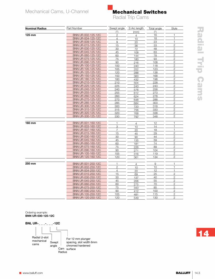
Total angle(°)1618233348637893108118123138168198228243258273278288303318333338348
1214182944597489104119134
910122540557085100115130
S Arc length(mm)
410203672108144180216240252288360432504240576612624648684720756768792
410204590135181226271316361
4102069137206275343412481549
Part Number
BNN UR-002-125-12CBNN UR-004-125-12CBNN UR-009-125-12CBNN UR-015-125-12CBNN UR-030-125-12CBNN UR-045-125-12CBNN UR-060-125-12CBNN UR-075-125-12CBNN UR-090-125-12CBNN UR-100-125-12CBNN UR-105-125-12CBNN UR-120-125-12CBNN UR-150-125-12CBNN UR-180-125-12CBNN UR-210-125-12CBNN UR-225-125-12CBNN UR-240-125-12CBNN UR-255-125-12CBNN UR-260-125-12CBNN UR-270-125-12CBNN UR-285-125-12CBNN UR-300-125-12CBNN UR-315-125-12CBNN UR-320-125-12CBNN UR-330-125-12C
BNN UR-001-160-12CBNN UR-003-160-12CBNN UR-007-160-12CBNN UR-015-160-12CBNN UR-030-160-12CBNN UR-045-160-12CBNN UR-060-160-12CBNN UR-075-160-12CBNN UR-090-160-12CBNN UR-105-160-12CBNN UR-120-160-12C
BNN UR-001-250-12CBNN UR-002-250-12CBNN UR-004-250-12CBNN UR-015-250-12CBNN UR-030-250-12CBNN UR-045-250-12CBNN UR-060-250-12CBNN UR-075-250-12CBNN UR-090-250-12CBNN UR-105-250-12CBNN UR-120-250-12C
Ordering example:BNN UR-030-125-12C
BNL UR-_ _ _-_ _ _-12C
Cam Radius
Radial U-slot mechanical cams
Swept angle
For 12 mm plunger spacing, slot width 6mm chromed hardened surface
Nominal Radius
125 mm
160 mm
250 mm
Swept angle(°)249153045607590100105120150180210225240255260270285300315320330
137153045607590105120
124153045607590105120
Radial Trip CamsMechanical Cams, U-Channel

Mechanical Switches
14.4
TypeCam drumSwitch
Nominal Radius
40 mm
50 mm
75 mm
100 mm
BNN TRBNL TRN, BNL LAH
61, 62, 72, 100, 602-11, 605-11, 610-11, 611-11, 612-11, 613-11
Style 2
Style 1
Total angle(°)4652577287116131156
3742496378104119134
263038607590105120
191922273756678297112127144
S Arc length(mm)
410142841556983
410163349658298
41023466992114137
441020295688118147177206236
Style
11111222
11111222
11122222
111122222222
Part number
BNN TR-004-040-12CBNN TR-010-040-12CBNN TR-015-040-12CBNN TR-030-040-12CBNN TR-045-040-12CBNN TR-060-040-12CBNN TR-075-040-12CBNN TR-090-040-12C
BNN TR-004-050-12CBNN TR-009-050-12CBNN TR-015-050-12CBNN TR-030-050-12CBNN TR-045-050-12CBNN TR-060-050-12CBNN TR-075-050-12CBNN TR-090-050-12C
BNN TR-003-075-12CBNN TR-007-075-12CBNN TR-015-075-12CBNN TR-030-075-12CBNN TR-045-075-12CBNN TR-060-075-12CBNN TR-075-075-12CBNN TR-090-075-12C
BNN TR-002-100-12CBNN TR-003-100-12CBNN TR-005-100-12CBNN TR-010-100-12CBNN TR-015-100-12CBNN TR-030-100-12CBNN TR-045-100-12CBNN TR-060-100-12CBNN TR-075-100-12CBNN TR-090-100-12CBNN TR-105-100-12CBNN TR-120-100-12C
Swept angle(°)410153045607590
49153045607590
37153045607590
23510153045607590105120
T-slot Installation: Tightening the screw causes the plate to raise and sandwich the T-flage between the plate and cam, securing the cam to the drum
Replacement End Ramps:Radius Part number40-50 mm BNN TRE-040-1275-124 mm BNN TRE-75-12125-249 mm BNN TRE-125-12
Replacement Pressure Block:BNN URENU-1202
Note:Cams used in safety appli-cations must be permanently secured to the cam drum. For safety applications, use: SCHNEIDSHR.D7513-M4x20ST-BE 718329
Material:Steel with hardened burnished surface and chrome plated. HRC 63+2
Dimensions in mm.
Additional radii and swept angles available on requst (quantities may be required).
See ordering example on bottom of page 13.5.
Radial Trip CamsMechanical Cams, T-Slot
Mechanical Switches
14.5n www.balluff.com
Radia
l Trip C
am
s
14
Nominal Radius
125 mm
160 mm
250 mm
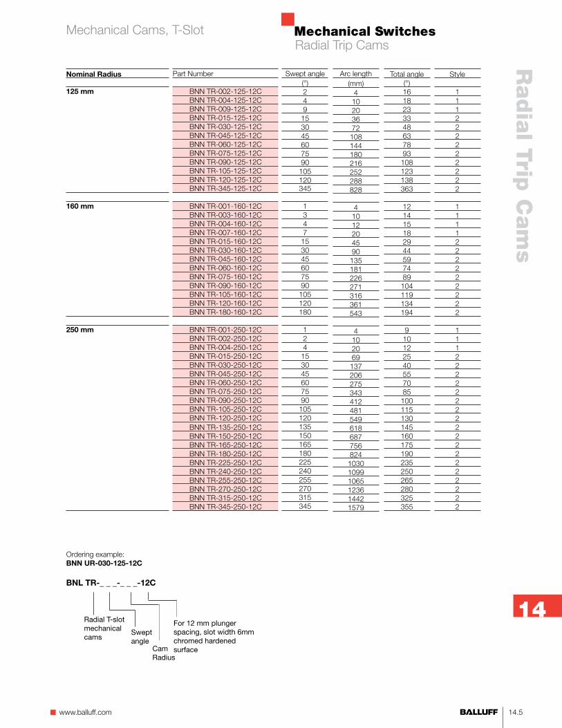
Style
111222222222
1111222222222
111222222222222222222
Total angle(°)1618233348637893108123138363
121415182944597489104119134194
910122540557085100115130145160175190235250265280325355
Arc length(mm)
410203672108144180216252288828
41012204590135181226271316361543
4102069137206275343412481549618687756824103010991065123614421579
Part Number
BNN TR-002-125-12CBNN TR-004-125-12CBNN TR-009-125-12CBNN TR-015-125-12CBNN TR-030-125-12CBNN TR-045-125-12CBNN TR-060-125-12CBNN TR-075-125-12CBNN TR-090-125-12CBNN TR-105-125-12CBNN TR-120-125-12CBNN TR-345-125-12C
BNN TR-001-160-12CBNN TR-003-160-12CBNN TR-004-160-12CBNN TR-007-160-12CBNN TR-015-160-12CBNN TR-030-160-12CBNN TR-045-160-12CBNN TR-060-160-12CBNN TR-075-160-12CBNN TR-090-160-12CBNN TR-105-160-12CBNN TR-120-160-12CBNN TR-180-160-12C
BNN TR-001-250-12CBNN TR-002-250-12CBNN TR-004-250-12CBNN TR-015-250-12CBNN TR-030-250-12CBNN TR-045-250-12CBNN TR-060-250-12CBNN TR-075-250-12CBNN TR-090-250-12CBNN TR-105-250-12CBNN TR-120-250-12CBNN TR-135-250-12CBNN TR-150-250-12CBNN TR-165-250-12CBNN TR-180-250-12CBNN TR-225-250-12CBNN TR-240-250-12CBNN TR-255-250-12CBNN TR-270-250-12CBNN TR-315-250-12CBNN TR-345-250-12C
Swept angle(°)249153045607590105120345
1347153045607590105120180
124153045607590105120135150165180225240255270315345
Ordering example:BNN UR-030-125-12C
BNL TR-_ _ _-_ _ _-12C
Cam Radius
Radial T-slot mechanical cams
Swept angle
For 12 mm plunger spacing, slot width 6mm chromed hardened surface
Radial Trip CamsMechanical Cams, T-Slot

Mechanical Switches
14.6
TypeCamSwitch
Nominal Radius
40 mm
50 mm
75 mm
100 mm
BEN IRBNL TRN
602-11, 605-11, 610-11, 611-11, 612-11, 613-11
Arc length(mm)
410142841556983
410163349658298
41023466992114137
41020295688118147177206236
Style
12223333
12223333
12223333
12222333333
Part number
BEN IR-004-040-12BEN IR-010-040-12BEN IR-015-040-12BEN IR-030-040-12BEN IR-045-040-12BEN IR-060-040-12BEN IR-075-040-12BEN IR-090-040-12
BEN IR-004-050-12BEN IR-009-050-12BEN IR-015-050-12BEN IR-030-050-12BEN IR-045-050-12BEN IR-060-050-12BEN IR-075-050-12BEN IR-090-050-12
BEN IR-003-075-12BEN IR-007-075-12BEN IR-015-075-12BEN IR-030-075-12BEN IR-045-075-12BEN IR-060-075-12BEN IR-075-075-12BEN IR-090-075-12
BEN IR-003-100-12BEN IR-005-100-12BEN IR-010-100-12BEN IR-015-100-12BEN IR-030-100-12BEN IR-045-100-12BEN IR-060-100-12BEN IR-075-100-12BEN IR-090-100-12BEN IR-105-100-12BEN IR-120-100-12
Style 2
Swept angle(°)410153045607590
49153045607590
37153045607590
3510153045607590105120
Style 1 Style 2 Style 3
T-slot Installation: BEN IR cams use channel locks. As the screw is tightened, the lock is raised to the T-flange and conforms to the drum.
Replacement Channel Lock without ScrewBEN IRNU-1202
Note:Cams used in safety appli-cations must be permanently secured to the cam drum.
BEN style cams are intended for non-contact operations of inductive sensors only. Mis- applications for use as trip cams for mechanical limit switches will result in extremely rapid wear and failure.
Material:Mild solid steel, Oxide coated.
Dimensions in mm.
Additional radii and swept angles available on requst (quantities may be required).
See ordering example on bottom of page 14.7.
Radial Trip CamsInductive Cams, T-Slot

Mechanical Switches
14.7n www.balluff.com
Radia
l Trip C
am
s
14
Ordering example:
BNL IR-_ _ _-_ _ _-12
Cam Radius
Radial T-slot inductive cams
Swept angle
For 12 mm plunger spacing, slot width 6mm, inductive, non-contact
Nominal Radius
125 mm
160 mm
250 mm
Style
12223333333
12222333333
22333333333
Swept angle(°)249153045607590105120
137153045607590105120
124153045607590105120
Part Number
BEN IR-002-125-12BEN IR-004-125-12BEN IR-009-125-12BEN IR-015-125-12BEN IR-030-125-12BEN IR-045-125-12BEN IR-060-125-12BEN IR-075-125-12BEN IR-090-125-12BEN IR-105-125-12BEN IR-120-125-12
BEN IR-001-160-12BEN IR-003-160-12BEN IR-007-160-12BEN IR-015-160-12BEN IR-030-160-12BEN IR-045-160-12BEN IR-060-160-12BEN IR-075-160-12BEN IR-090-160-12BEN IR-105-160-12BEN IR-120-160-12
BEN IR-001-250-12BEN IR-002-250-12BEN IR-004-250-12BEN IR-015-250-12BEN IR-030-250-12BEN IR-045-250-12BEN IR-060-250-12BEN IR-075-250-12BEN IR-090-250-12BEN IR-105-250-12BEN IR-120-250-12
Arc length(mm)
410203672108144180216252288
410204590135181226271316361
4102069137206275343412481549
Radial Trip CamsInductive Cams, T-Slot
Mechanical Switches
14.8
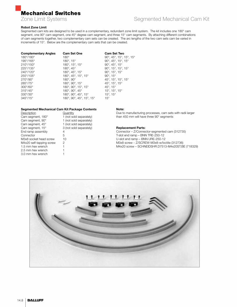
Robot Zone LimitSegmented cam kits are designed to be used in a complementary, redundant zone limit system. The kit includes one 180° cam segment, one 90° cam segment, one 45° degree cam segment, and three 15° cam segments. By attaching different combinations of cam segments together, two complementary cam sets can be created. The arc lengths of the two cam sets cam be varied in increments of 15°. Below are the complementary cam sets that can be created.
Complementary Angles Cam Set One Cam Set Two180°/180° 180° 90°, 45°, 15°, 15°, 15°195°/165° 180°, 15° 90°, 45°, 15°, 15°210°/150° 180°, 15°, 15° 90°, 45°, 15°225°/135° 180°, 45° 90°, 15°, 15°, 15°240°/120° 180°, 45°, 15° 90°, 15°, 15°255°/105° 180°, 45°, 15°, 15° 90°, 15°270°/90° 180°, 90° 45°, 15°, 15°, 15°285°/75° 180°, 90°, 15° 45°, 15°, 15°300°/60° 180°, 90°, 15°, 15° 45°, 15°315°/45° 180°, 90°, 45° 15°, 15°, 15°330°/30° 180°, 90°, 45°, 15° 15°, 15°345°/15° 180°, 90°, 45°, 15°, 15° 15°
Segmented Mechanical Cam Kit Package ContentsDescription QuantityCam segment, 180° 1 (not sold separately)Cam segment, 90° 1 (not sold separately)Cam segment, 45° 1 (not sold separately)Cam segment, 15° 3 (not sold separately)End ramp assembly 4Connector 5M3x8 socket head screw 10M4x20 self-tapping screw 21.5 mm hex wrench 12.5 mm hex wrench 13.0 mm hex wrench 1
Note:Due to manufacturing processes, cam sets with radii larger than 450 mm will have three 90° segments
Replacement Parts:Connector – Z/Connector-segmented cam (312735)T-slot end ramp – BNN TRE-250-12U-slot end ramp – BNN URE-250-12M3x8 screw – Z/SCREW-M3x8-w/loctite (312736)M4x20 screw – SCHNEIDSHR.D7513-M4x20ST.BE (718329)
Zone Limit Systems Segmented Mechanical Cam Kit
Mechanical Switches
14.9n www.balluff.com
Radia
l Trip C
am
s
14
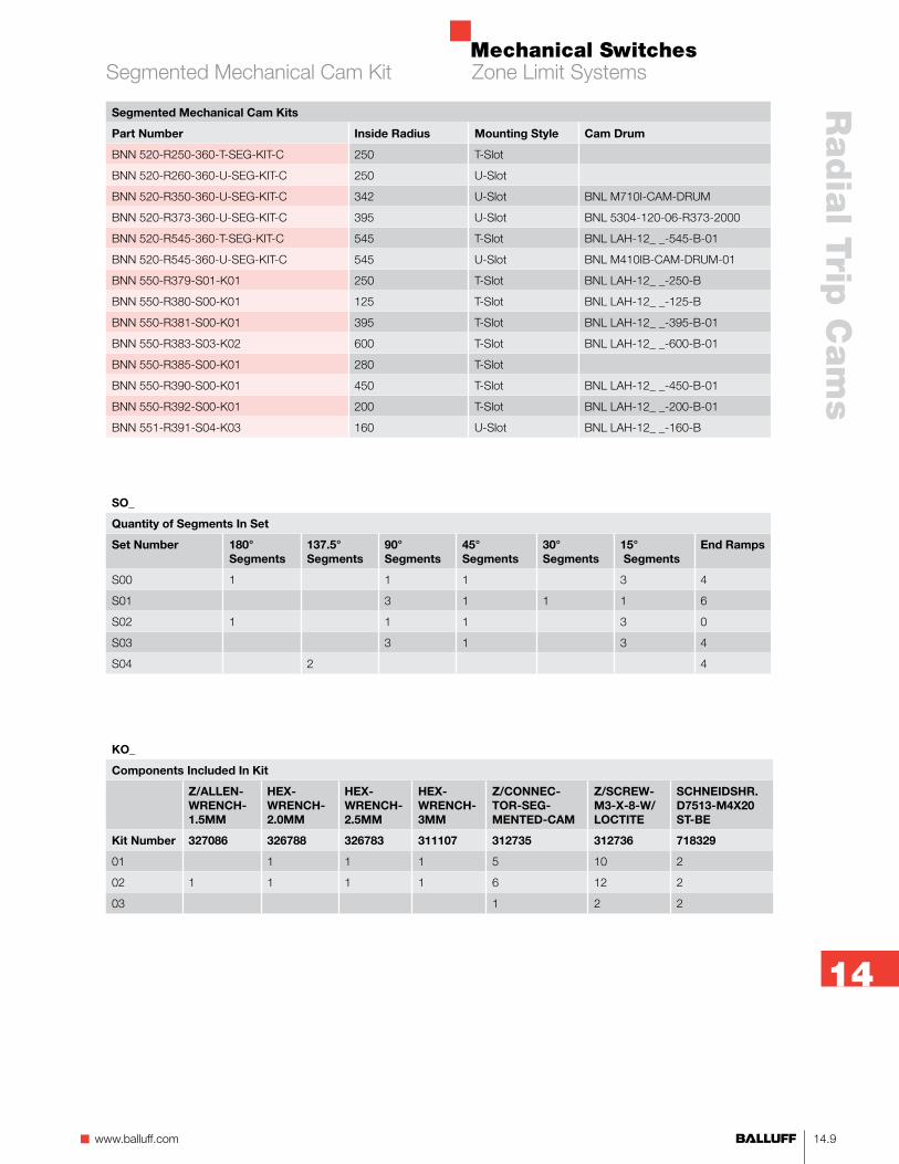
Segmented Mechanical Cam Kits
Part Number Inside Radius Mounting Style Cam Drum
BNN 520-R250-360-T-SEG-KIT-C 250 T-Slot
BNN 520-R260-360-U-SEG-KIT-C 250 U-Slot
BNN 520-R350-360-U-SEG-KIT-C 342 U-Slot BNL M710I-CAM-DRUM
BNN 520-R373-360-U-SEG-KIT-C 395 U-Slot BNL 5304-120-06-R373-2000
BNN 520-R545-360-T-SEG-KIT-C 545 T-Slot BNL LAH-12_ _-545-B-01
BNN 520-R545-360-U-SEG-KIT-C 545 U-Slot BNL M410IB-CAM-DRUM-01
BNN 550-R379-S01-K01 250 T-Slot BNL LAH-12_ _-250-B
BNN 550-R380-S00-K01 125 T-Slot BNL LAH-12_ _-125-B
BNN 550-R381-S00-K01 395 T-Slot BNL LAH-12_ _-395-B-01
BNN 550-R383-S03-K02 600 T-Slot BNL LAH-12_ _-600-B-01
BNN 550-R385-S00-K01 280 T-Slot
BNN 550-R390-S00-K01 450 T-Slot BNL LAH-12_ _-450-B-01
BNN 550-R392-S00-K01 200 T-Slot BNL LAH-12_ _-200-B-01
BNN 551-R391-S04-K03 160 U-Slot BNL LAH-12_ _-160-B
SO_
Quantity of Segments In Set
Set Number 180° Segments
137.5° Segments
90° Segments
45° Segments
30° Segments
15° Segments
End Ramps
S00 1 1 1 3 4
S01 3 1 1 1 6
S02 1 1 1 3 0
S03 3 1 3 4
S04 2 4
KO_
Components Included In Kit
Z/ALLEN-WRENCH-1.5MM
HEX-WRENCH-2.0MM
HEX-WRENCH-2.5MM
HEX-WRENCH-3MM
Z/CONNEC-TOR-SEG-MENTED-CAM
Z/SCREW-M3-X-8-W/LOCTITE
SCHNEIDSHR.D7513-M4X20 ST-BE
Kit Number 327086 326788 326783 311107 312735 312736 718329
01 1 1 1 5 10 2
02 1 1 1 1 6 12 2
03 1 2 2
Zone Limit SystemsSegmented Mechanical Cam Kit

Mechanical Switches
14.10
Robot Zone LimitSegmented cam kits are designed to be used in a complementary, redundant zone limit system. The kit includes one 180° cam segment, one 90° cam segment, one 45° degree cam segment, and three 15° cam segments. By attaching different combinations of cam segments together, two complementary cam sets can be created. The arc lengths of the two cam sets can be varied in increments of 15°. Below are the complementary cam sets that can be created.
Complementary Angles Cam Set One Cam Set Two180°/180° 180° 90°, 45°, 15°, 15°, 15°195°/165° 180°, 15° 90°, 45°, 15°, 15°210°/150° 180°, 15°, 15° 90°, 45°, 15°225°/135° 180°, 45° 90°, 15°, 15°, 15°240°/120° 180°, 45°, 15° 90°, 15°, 15°255°/105° 180°, 45°, 15°, 15° 90°, 15°270°/90° 180°, 90° 45°, 15°, 15°, 15°285°/75° 180°, 90°, 15° 45°, 15°, 15°300°/60° 180°, 90°, 15°, 15° 45°, 15°315°/45° 180°, 90°, 45° 15°, 15°, 15°330°/30° 180°, 90°, 45°, 15° 15°, 15°345°/15° 180°, 90°, 45°, 15°, 15° 15°
Segmented Non-Contact Cam Kit Package ContentsDescription QuantityCam segment, 180° 1 (not sold separately)Cam segment, 90° 1 (not sold separately)Cam segment, 45° 1 (not sold separately)Cam segment, 15° 3 (not sold separately)M4x20 screws 14Special M4 nut 142.5 mm hex wrench 1
Note:BEN style cams are intended for non-contact operations of inductive sensors only. Mis-applications for use as trip cams for mechanical limit switches will result in extremely rapid wear and failure.
Replacement Parts:M4x20 screw – Z/SCREW-SHCS-M4-X-20-FH (317248)M4 T-nut – NOCKENKOERPER-ROHTEIL 516-17 (149398)Tamper proof label – Label Tamper Proof (167282)Spanner screwdriver bit – Spanner BIT 1/4 Hex (167279)Tamper proof spanner screw – SCREW Spanner M4X25 DIN 7167 (167208)
Zone Limit Systems Segmented Inductive Cam Kit

Mechanical Switches
14.11n www.balluff.com
Radia
l Trip C
am
s
14
Segmented Non-Contact Cam Kits
Part Number Inside Radius Mounting Style Cam Drum
BEN 516-17-R210,0-S00-K01 200 T-Slot BNL LAH-12_ _-200-B-01
BEN 516-17-R260,0-S00-K01 250 T-Slot BNL LAH-12_ _-250-B
BEN 516-17-R290,0-S00-K01 280 T-Slot
BEN 516-17-R405,0-S00-K01 395 T-Slot BNL LAH-12_ _-395-B-01
BEN 516-17-R460,0-S00-K01 450 T-Slot BNL LAH-12_ _-450-B-01
BEN 516-17-R555,0-S00-K01 545 T-Slot BNL LAH-12_ _-545-B-01
SO_
Quantity of Segments In Set
Set Number 180° Segments
90° Segments
45° Segments
15° Segments
S00 1 1 1 3
KO_
Components Included In Kit
HEX-WRENCH-2.5MM M4 T-Nut Z/SCREW-SHCS-M4-X-20-FH
Kit Number 326783 149398 317248
01 1 14 14
02 1
03
Zone Limit SystemsSegmented Inductive Cam Kit

Mechanical Switches
14.12
Mechanical Switches
15.1n www.balluff.com
Accesso
ries
15
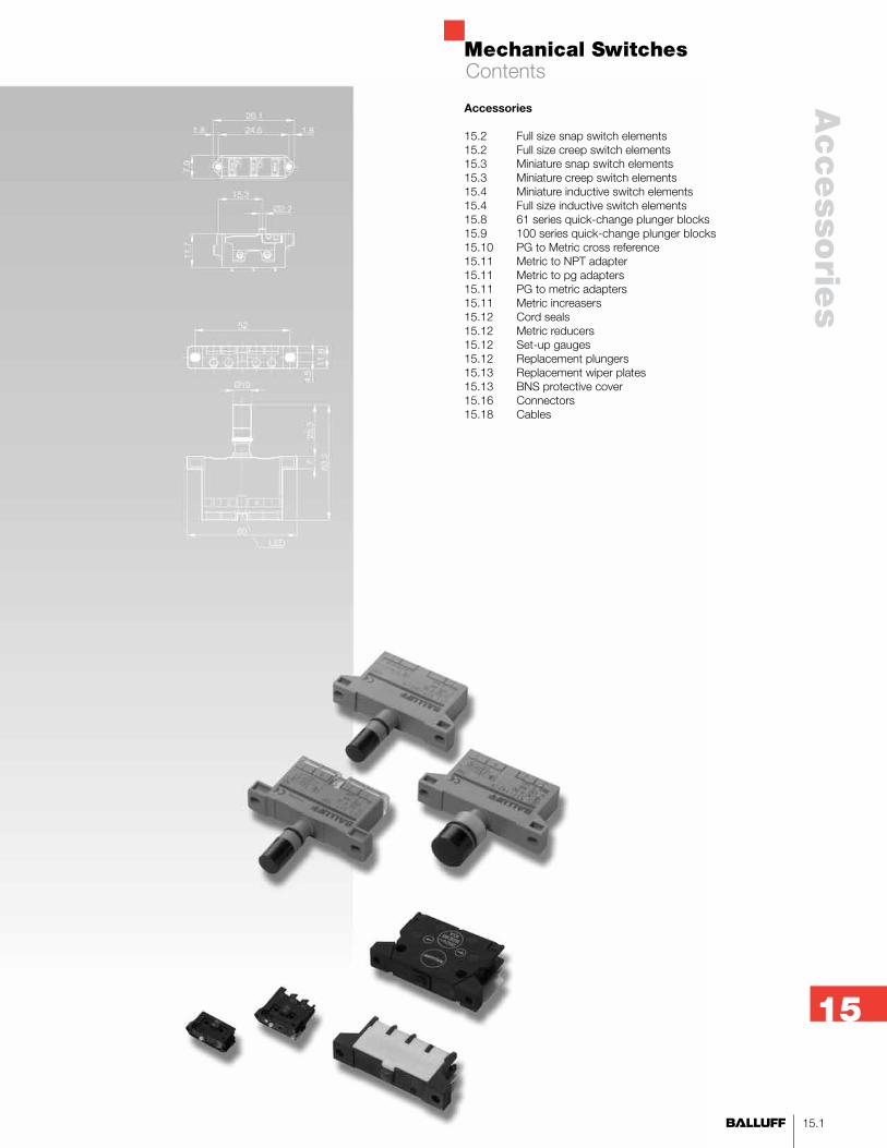
Accessories
15.2 Full size snap switch elements15.2 Full size creep switch elements15.3 Miniature snap switch elements15.3 Miniature creep switch elements15.4 Miniature inductive switch elements15.4 Full size inductive switch elements15.8 61 series quick-change plunger blocks15.9 100 series quick-change plunger blocks15.10 PG to Metric cross reference15.11 Metric to NPT adapter15.11 Metric to pg adapters15.11 PG to metric adapters15.11 Metric increasers15.12 Cord seals15.12 Metric reducers15.12 Set-up gauges15.12 Replacement plungers15.13 Replacement wiper plates15.13 BNS protective cover15.16 Connectors15.18 Cables
Contents
Mechanical Switches
15.2
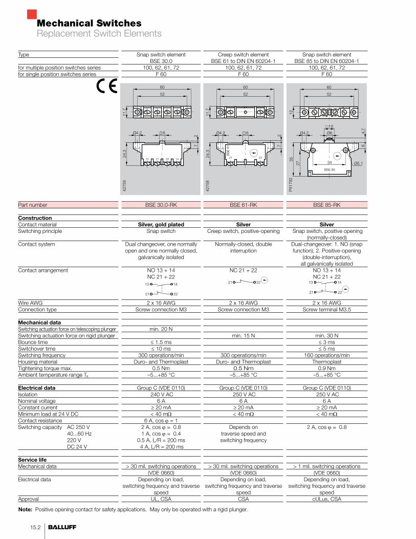
Snap switch element BSE 30.0
100, 62, 61, 72F 60
BSE 30.0-RK
Silver, gold platedSnap switch
Dual changeover, one normally open and one normally closed,
galvanically isolated
NO 13 + 14NC 21 + 22
2 x 16 AWGScrew connection M3
min. 20 N
≤ 1.5 ms≤ 10 ms
300 operations/minDuro- and Thermoplast
0.5 Nm–5...+85 °C
Group C (VDE 0110) 240 V AC
6 A≥ 20 mA< 40 mΩ
6 A, cos ϕ = 12 A, cos ϕ = 0.81 A, cos ϕ = 0.4
0.5 A, L/R = 200 ms 4 A, L/R = 200 ms
> 30 mil. switching operations(VDE 0660)
Depending on load, switching frequency and traverse
speedUL, CSA
Snap switch element BSE 85 to DIN EN 60204-1
100, 62, 61, 72F 60
BSE 85-RK
Silver Snap switch, positive opening
(normally-closed)Dual-changeover: 1. NO (snap function), 2. Positive-opening
(double-interruption), all galvanically isolated
NO 13 + 14NC 21 + 22
2 x 16 AWGScrew terminal M3.5
min. 30 N≤ 3 ms≤ 5 ms
160 operations/minThermoplast
0.9 Nm–5...+85 °C
Group C (VDE 0110) 250 V AC
6 A≥ 20 mA< 40 mΩ
2 A, cos ϕ = 0.8
> 1 mil. switching operations(VDE 0660)
Depending on load, switching frequency and traverse
speed cULus, CSA
Creep switch element BSE 61 to DIN EN 60204-1
100, 62, 61, 72F 60
BSE 61-RK
SilverCreep switch, positive-opening
Normally-closed, double interruption
NC 21 + 22
2 x 16 AWGScrew connection M3
min. 15 N
300 operations/minDuro- and Thermoplast
0.5 Nm–5...+85 °C
Group C (VDE 0110) 250 V AC
6 A≥ 20 mA< 40 mΩ
Depends on traverse speed and switching frequency
> 30 mil. switching operations(VDE 0660)
Depending on load, switching frequency and traverse
speedCSA
Type
for multiple position switches seriesfor single position switches series
Part number
ConstructionContact materialSwitching principle
Contact system
Contact arrangement
Wire AWGConnection type
Mechanical dataSwitching actuation force on telescoping plungerSwitching actuation force on rigid plunger Bounce timeSwitchover timeSwitching frequencyHousing materialTightening torque max.Ambient temperature range Ta
Electrical dataIsolationNominal voltageConstant currentMinimum load at 24 V DCContact resistanceSwitching capacity AC 250 V 40...60 Hz 220 V DC 24 V
Service lifeMechanical data
Electrical data
Approval
Note: Positive opening contact for safety applications. May only be operated with a rigid plunger.
Replacement Switch Elements
Mechanical Switches
15.3n www.balluff.com
Accesso
ries
15
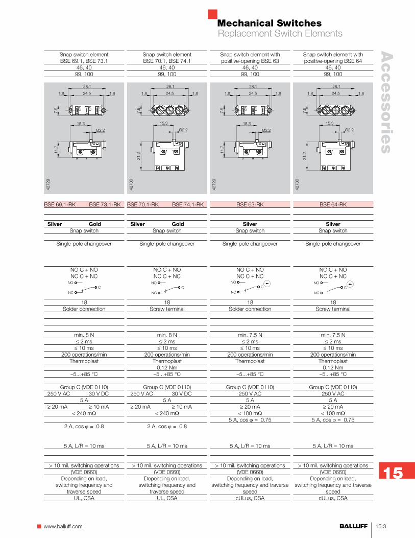
Snap switch elementBSE 70.1, BSE 74.1
46, 4099, 100
BSE 70.1-RK BSE 74.1-RK
Silver GoldSnap switch
Single-pole changeover
NO C + NONC C + NC
18Screw terminal
min. 8 N≤ 2 ms≤ 10 ms
200 operations/minThermoplast
0.12 Nm–5...+85 °C
Group C (VDE 0110) 250 V AC 30 V DC
5 A ≥ 20 mA ≥ 10 mA
< 240 mΩ
2 A, cos ϕ = 0.8
5 A, L/R = 10 ms
> 10 mil. switching operations(VDE 0660)
Depending on load, switching frequency and
traverse speedUL, CSA
Snap switch elementBSE 69.1, BSE 73.1
46, 4099, 100
BSE 69.1-RK BSE 73.1-RK
Silver GoldSnap switch
Single-pole changeover
NO C + NONC C + NC
18Solder connection
min. 8 N≤ 2 ms≤ 10 ms
200 operations/minThermoplast
–5...+85 °C
Group C (VDE 0110) 250 V AC 30 V DC
5 A ≥ 20 mA ≥ 10 mA
< 240 mΩ
2 A, cos ϕ = 0.8
5 A, L/R = 10 ms
> 10 mil. switching operations(VDE 0660)
Depending on load, switching frequency and
traverse speedUL, CSA
Snap switch element with positive-opening BSE 63
46, 4099, 100
BSE 63-RK
SilverSnap switch
Single-pole changeover
NO C + NONC C + NC
18Solder connection
min. 7.5 N≤ 2 ms≤ 10 ms
200 operations/minThermoplast
–5...+85 °C
Group C (VDE 0110)250 V AC
5 A≥ 20 mA
< 100 mΩ5 A, cos ϕ = 0.75
5 A, L/R = 10 ms
> 10 mil. switching operations(VDE 0660)
Depending on load, switching frequency and traverse
speedcULus, CSA
Snap switch element with positive-opening BSE 64
46, 4099, 100
BSE 64-RK
SilverSnap switch
Single-pole changeover
NO C + NONC C + NC
18Screw terminal
min. 7.5 N≤ 2 ms≤ 10 ms
200 operations/minThermoplast
0.12 Nm–5...+85 °C
Group C (VDE 0110)250 V AC
5 A≥ 20 mA
< 100 mΩ5 A, cos ϕ = 0.75
5 A, L/R = 10 ms
> 10 mil. switching operations(VDE 0660)
Depending on load, switching frequency and traverse
speedcULus, CSA
Replacement Switch Elements
Mechanical Switches
15.4
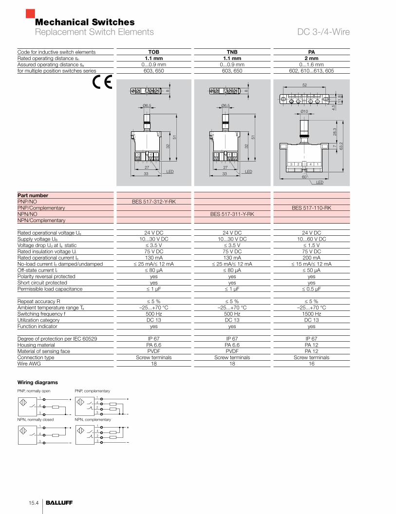
Code for inductive switch elementsRated operating distance sn
Assured operating distance sa
for multiple position switches series
Part numberPNP/NO PNP/Complementary NPN/NONPN/Complementary Rated operational voltage Ue
Supply voltage UB
Voltage drop Ud at Ie staticRated insulation voltage Ui
Rated operational current IeNo-load current I0 damped/undampedOff-state current IrPolarity reversal protectedShort circuit protectedPermissible load capacitance
Repeat accuracy RAmbient temperature range Ta
Switching frequency fUtilization categoryFunction indicator
Degree of protection per IEC 60529 Housing materialMaterial of sensing faceConnection typeWire AWG
Wiring diagrams
PA2 mm
0...1.6 mm602, 610...613, 605
BES 517-110-RK
24 V DC10...60 V DC
≤ 1.5 V75 V DC200 mA
≤ 15 mA/≤ 12 mA≤ 50 µA
yesyes
≤ 0.5 µF
≤ 5 %–25...+70 °C
1500 HzDC 13
yes
IP 67PA 12PA 12
Screw terminals16
TNB1.1 mm
0...0.9 mm603, 650
BES 517-311-Y-RK
24 V DC10...30 V DC
≤ 3.5 V75 V DC130 mA
≤ 25 mA/≤ 12 mA≤ 80 µA
yesyes
≤ 1 µF
≤ 5 %–25...+70 °C
500 HzDC 13
yes
IP 67PA 6.6PVDF
Screw terminals18
TOB1.1 mm
0...0.9 mm603, 650
BES 517-312-Y-RK
24 V DC10...30 V DC
≤ 3.5 V75 V DC130 mA
≤ 25 mA/≤ 12 mA≤ 80 µA
yesyes
≤ 1 µF
≤ 5 %–25...+70 °C
500 HzDC 13
yes
IP 67PA 6.6PVDF
Screw terminals18
PNP, normally open
NPN, normally closed
PNP, complementary
NPN, complementary
Replacement Switch Elements DC 3-/4-Wire
Mechanical Switches
15.5n www.balluff.com
Accesso
ries
15
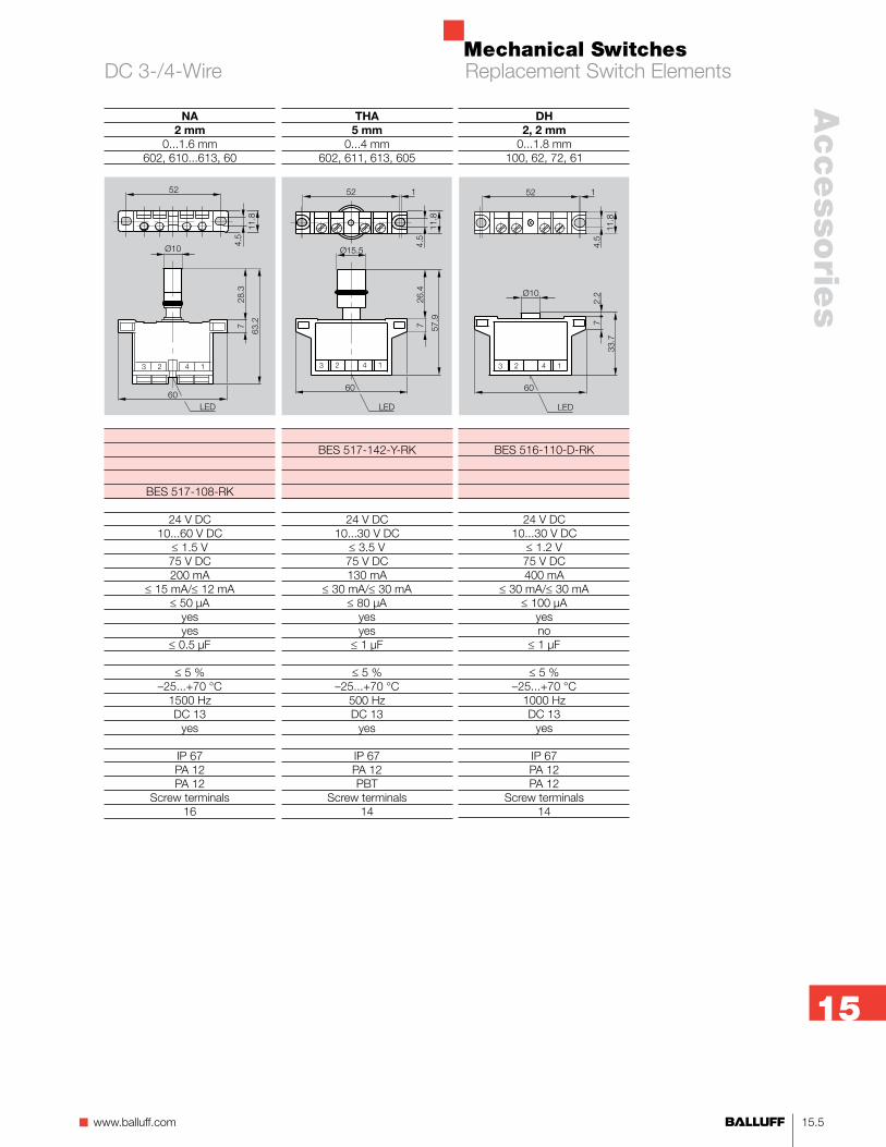
DH2, 2 mm
0...1.8 mm 100, 62, 72, 61
BES 516-110-D-RK
24 V DC10...30 V DC
≤ 1.2 V75 V DC400 mA
≤ 30 mA/≤ 30 mA≤ 100 µA
yesno
≤ 1 µF
≤ 5 %–25...+70 °C
1000 HzDC 13
yes
IP 67PA 12PA 12
Screw terminals14
THA5 mm
0...4 mm602, 611, 613, 605
BES 517-142-Y-RK
24 V DC10...30 V DC
≤ 3.5 V75 V DC130 mA
≤ 30 mA/≤ 30 mA≤ 80 µA
yesyes
≤ 1 µF
≤ 5 %–25...+70 °C
500 HzDC 13
yes
IP 67PA 12PBT
Screw terminals14
NA2 mm
0...1.6 mm602, 610...613, 60
BES 517-108-RK
24 V DC10...60 V DC
≤ 1.5 V75 V DC200 mA
≤ 15 mA/≤ 12 mA≤ 50 µA
yesyes
≤ 0.5 µF
≤ 5 %–25...+70 °C
1500 HzDC 13
yes
IP 67PA 12PA 12
Screw terminals16
Replacement Switch ElementsDC 3-/4-Wire

Mechanical Switches
15.6
WS2 mm
0...1.6 mm 602, 610...613, 605
BES 517-410-RK
110 V AC35...250 V AC
≤ 8.5 V250 V AC100 mA
≤ 1700 µAyesno
≤ 5 %–25...+70 °C
10 HzAC 140
yes
IP 67PA
PA 12Screw terminals
14cULus
EJA5 mm
0...4 mm 602, 611, 613, 605
BES 517-463-RK
220 V AC90...250 V AC
≤ 8.5 V250 V AC100 mA
≤ 3000 µAyesno
≤ 5 %–25...+70 °C
15 HzAC 140
yes
IP 67PA
PA 12Screw terminals
14cULus
WO2 mm
0...1.6 mm 602, 610...613, 605
BES 517-421-RK
110 V AC35...250 V AC
≤ 8.5 V250 V AC100 mA
≤ 1700 µAyesno
≤ 5 %–25...+70 °C
10 HzAC 140
yes
IP 67PA
PA 12Screw terminals
14cULus
AC, NO AC, NC
DC, NO DC, NC
NAMUR
Wiring diagrams
Code for inductive switch elementsRated operating distance snAssured operating distance safor multiple position switches series
for replacement switch elementsAC/NO AC/NC
DC/NODC/NCNAMUR
Rated operational voltage Ue
Supply voltage UB
Voltage drop Ud at Ie staticRated insulation voltage Ui
Rated operational current IeNo-load current I0 damped/undampedOff-state current IrPolarity reversal protectedShort circuit protectedPermissible load capacitance
Repeat accuracy RAmbient temperature range Ta
Switching frequency fUtilization categoryFunction indicator
Degree of protection per IEC 60529 Housing materialMaterial of sensing faceConnection typeWire AWGApproval
Replacement Switch Elements AC/DC 2-Wire
Mechanical Switches
15.7n www.balluff.com
Accesso
ries
15
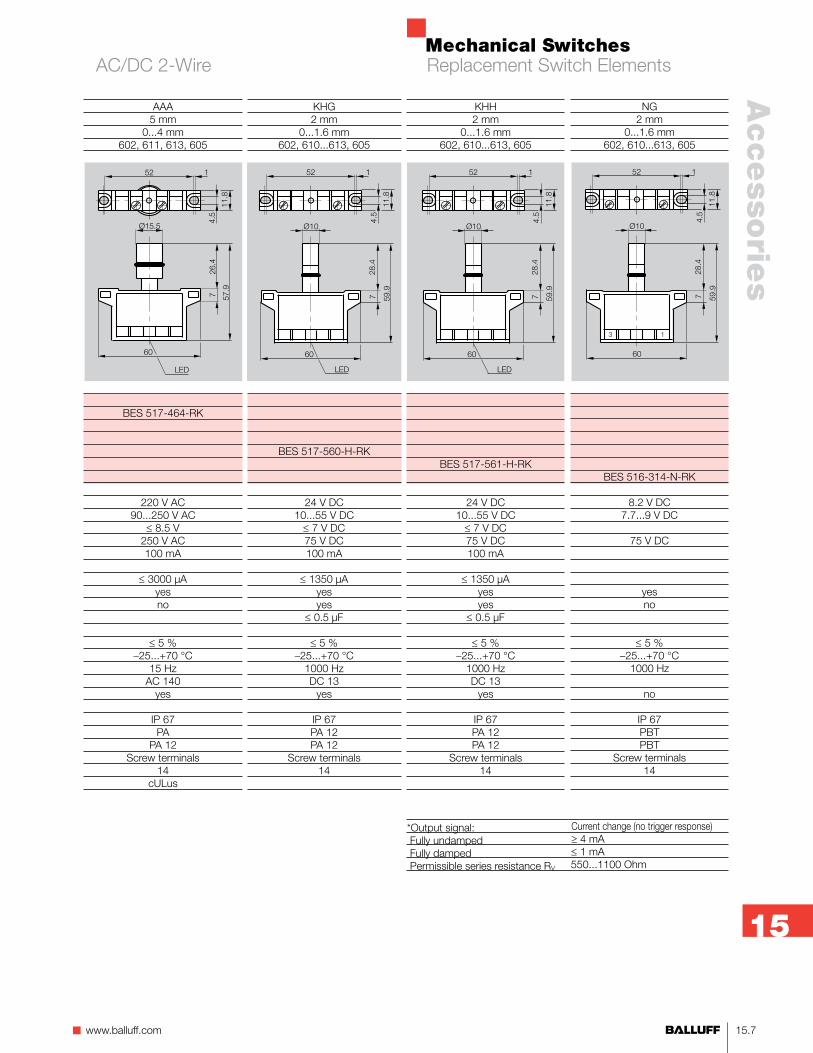
KHG2 mm
0...1.6 mm 602, 610...613, 605
BES 517-560-H-RK
24 V DC10...55 V DC≤ 7 V DC75 V DC100 mA
≤ 1350 µAyesyes
≤ 0.5 µF
≤ 5 %–25...+70 °C
1000 HzDC 13
yes
IP 67PA 12PA 12
Screw terminals14
NG2 mm
0...1.6 mm 602, 610...613, 605
BES 516-314-N-RK
8.2 V DC7.7...9 V DC
75 V DC
yesno
≤ 5 %–25...+70 °C
1000 Hz
no
IP 67PBTPBT
Screw terminals14
KHH2 mm
0...1.6 mm 602, 610...613, 605
BES 517-561-H-RK
24 V DC10...55 V DC≤ 7 V DC75 V DC100 mA
≤ 1350 µAyesyes
≤ 0.5 µF
≤ 5 %–25...+70 °C
1000 HzDC 13
yes
IP 67PA 12PA 12
Screw terminals14
AAA5 mm
0...4 mm 602, 611, 613, 605
BES 517-464-RK
220 V AC90...250 V AC
≤ 8.5 V250 V AC100 mA
≤ 3000 µAyesno
≤ 5 %–25...+70 °C
15 HzAC 140
yes
IP 67PA
PA 12Screw terminals
14cULus
*Output signal: Current change (no trigger response) Fully undamped ≥ 4 mA Fully damped ≤ 1 mA Permissible series resistance RV 550...1100 Ohm
Replacement Switch ElementsAC/DC 2-Wire
Mechanical Switches
15.8
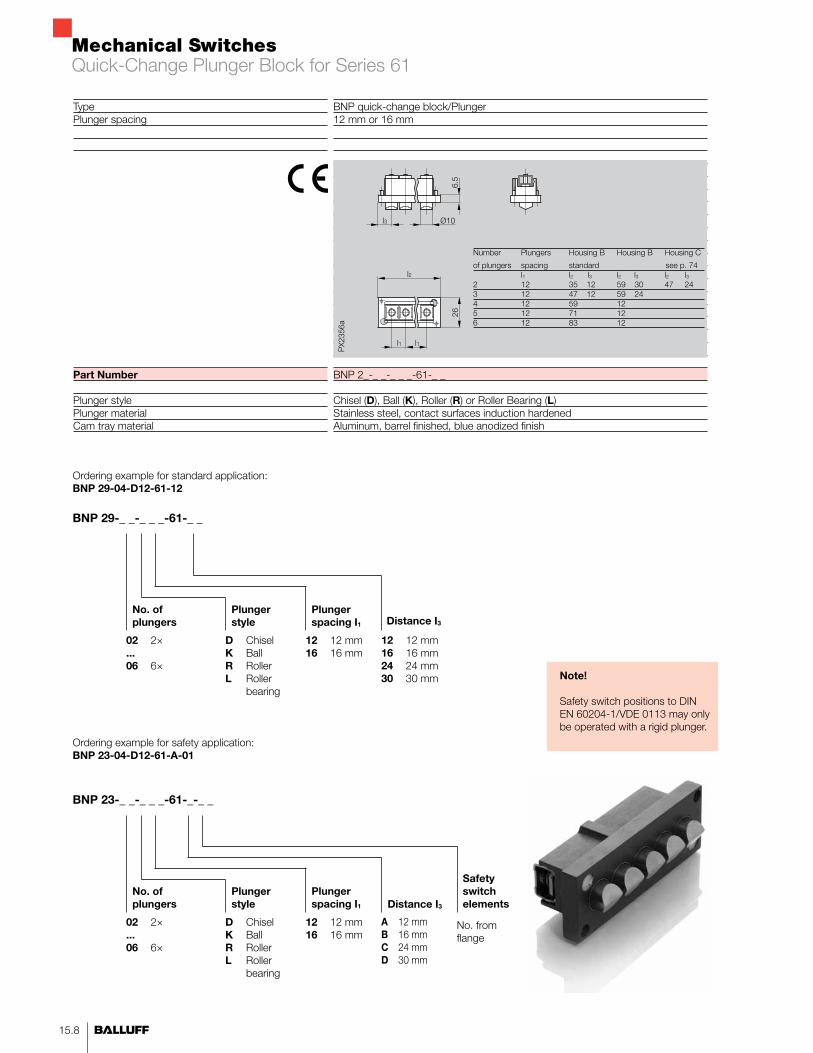
BNP quick-change block/Plunger12 mm or 16 mm
BNP 2_-_ _-_ _ _-61-_ _
Chisel (D), Ball (K), Roller (R) or Roller Bearing (L)Stainless steel, contact surfaces induction hardenedAluminum, barrel finished, blue anodized finish
TypePlunger spacing
Part Number
Plunger stylePlunger materialCam tray material
BNP 29-_ _-_ _ _-61-_ _
No. of plungers
Plunger style
Plunger spacing I1
12 12 mm 16 16 mm
02 2×...06 6×
D Chisel K Ball R Roller L Roller bearing
Ordering example for standard application:BNP 29-04-D12-61-12
12 12 mm 16 16 mm 24 24 mm 30 30 mm
Distance I3
Ordering example for safety application:BNP 23-04-D12-61-A-01
BNP 23-_ _-_ _ _-61-_-_ _
No. of plungers
Plunger style
Plunger spacing I1
12 12 mm 16 16 mm
02 2×...06 6×
D Chisel K Ball R Roller L Roller bearing
Distance I3
A 12 mm B 16 mm C 24 mm D 30 mm
Safety switch elements
No. from flange
Number Plungers Housing B Housing B Housing C
of plungers spacing standard see p. 74 l1 l2 l3 l2 l3 l2 l3 2 12 35 12 59 30 47 243 12 47 12 59 24 4 12 59 125 12 71 126 12 83 12
Note!
Safety switch positions to DIN EN 60204-1/VDE 0113 may only be operated with a rigid plunger.
Quick-Change Plunger Block for Series 61

Mechanical Switches
15.9n www.balluff.com
Accesso
ries
15
TypePlunger spacing
Part Number
Plunger stylePlunger materialCam tray material
BNP quick-change block/Plunger12 mm or 16 mm
BNP 2_-_ _-_ _ _-100
Chisel (D), Ball (K), Roller (R) or Roller Bearing (L)Stainless steel, contact surfaces induction hardenedaluminum, barrel finished, blue anodized finish
Ordering example for standard application:BNP 29-04-D12-100
BNP 29-_ _-_ _ _-100
No. of plungers
Plunger style
Plunger spacing I1
12 12 mm 16 16 mm
02 2×...06 6×
D Chisel K Ball R Roller L Roller bearing
Ordering example for safety application:BNP 23-04-D12-100-01
BNP 23-_ _-_ _ _-100-_ _
No. of plungers
Plunger style
Plunger spacing I1
12 12 mm 16 16 mm
02 2×...06 6×
D Chisel K Ball R Roller L Roller bearing
Safety switch elements
No. from flange
Number l2 for l2 for plunger l1 = 12 l1 = 16 2 68 68 3 78 88 4 88 102 5 102 118 6 118
Note!
Safety switch positions to DIN EN 60204-1/VDE 0113 may only be operated with a rigid plunger.
Quick-Change Plunger Block for Series 100
Mechanical Switches
15.10
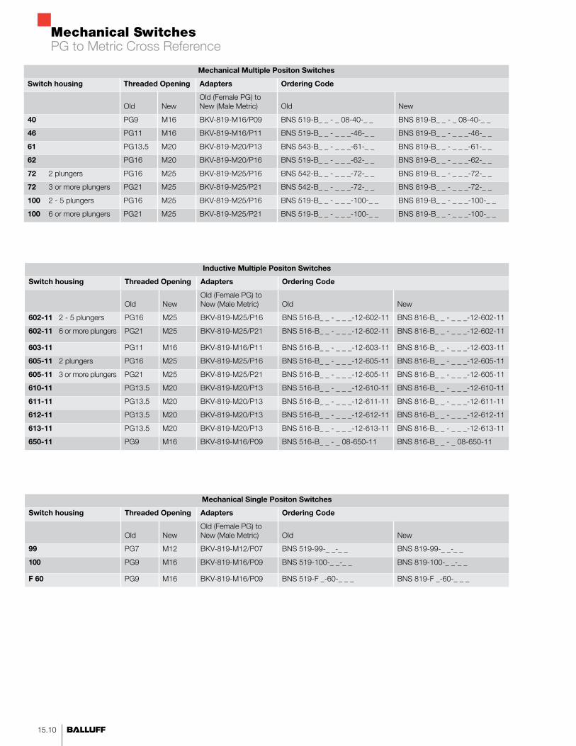
Mechanical Multiple Positon Switches
Switch housing Threaded Opening Adapters Ordering Code
Old
New
Old (Female PG) to New (Male Metric)
Old
New
40 PG9 M16 BKV-819-M16/P09 BNS 519-B_ _ - _ 08-40-_ _ BNS 819-B_ _ - _ 08-40-_ _
46 PG11 M16 BKV-819-M16/P11 BNS 519-B_ _ - _ _ _-46-_ _ BNS 819-B_ _ - _ _ _-46-_ _
61 PG13.5 M20 BKV-819-M20/P13 BNS 543-B_ _ - _ _ _-61-_ _ BNS 819-B_ _ - _ _ _-61-_ _
62 PG16 M20 BKV-819-M20/P16 BNS 519-B_ _ - _ _ _-62-_ _ BNS 819-B_ _ - _ _ _-62-_ _
72 2 plungers PG16 M25 BKV-819-M25/P16 BNS 542-B_ _ - _ _ _-72-_ _ BNS 819-B_ _ - _ _ _-72-_ _
72 3 or more plungers PG21 M25 BKV-819-M25/P21 BNS 542-B_ _ - _ _ _-72-_ _ BNS 819-B_ _ - _ _ _-72-_ _
100 2 - 5 plungers PG16 M25 BKV-819-M25/P16 BNS 519-B_ _ - _ _ _-100-_ _ BNS 819-B_ _ - _ _ _-100-_ _
100 6 or more plungers PG21 M25 BKV-819-M25/P21 BNS 519-B_ _ - _ _ _-100-_ _ BNS 819-B_ _ - _ _ _-100-_ _
Inductive Multiple Positon Switches
Switch housing Threaded Opening Adapters Ordering Code
Old
New
Old (Female PG) to New (Male Metric)
Old
New
602-11 2 - 5 plungers PG16 M25 BKV-819-M25/P16 BNS 516-B_ _ - _ _ _-12-602-11 BNS 816-B_ _ - _ _ _-12-602-11
602-11 6 or more plungers PG21 M25 BKV-819-M25/P21 BNS 516-B_ _ - _ _ _-12-602-11 BNS 816-B_ _ - _ _ _-12-602-11
603-11 PG11 M16 BKV-819-M16/P11 BNS 516-B_ _ - _ _ _-12-603-11 BNS 816-B_ _ - _ _ _-12-603-11
605-11 2 plungers PG16 M25 BKV-819-M25/P16 BNS 516-B_ _ - _ _ _-12-605-11 BNS 816-B_ _ - _ _ _-12-605-11
605-11 3 or more plungers PG21 M25 BKV-819-M25/P21 BNS 516-B_ _ - _ _ _-12-605-11 BNS 816-B_ _ - _ _ _-12-605-11
610-11 PG13.5 M20 BKV-819-M20/P13 BNS 516-B_ _ - _ _ _-12-610-11 BNS 816-B_ _ - _ _ _-12-610-11
611-11 PG13.5 M20 BKV-819-M20/P13 BNS 516-B_ _ - _ _ _-12-611-11 BNS 816-B_ _ - _ _ _-12-611-11
612-11 PG13.5 M20 BKV-819-M20/P13 BNS 516-B_ _ - _ _ _-12-612-11 BNS 816-B_ _ - _ _ _-12-612-11
613-11 PG13.5 M20 BKV-819-M20/P13 BNS 516-B_ _ - _ _ _-12-613-11 BNS 816-B_ _ - _ _ _-12-613-11
650-11 PG9 M16 BKV-819-M16/P09 BNS 516-B_ _ - _ 08-650-11 BNS 816-B_ _ - _ 08-650-11
Mechanical Single Positon Switches
Switch housing Threaded Opening Adapters Ordering Code
Old
New
Old (Female PG) to New (Male Metric)
Old
New
99 PG7 M12 BKV-819-M12/P07 BNS 519-99-_ _-_ _ BNS 819-99-_ _-_ _
100 PG9 M16 BKV-819-M16/P09 BNS 519-100-_ _-_ _ BNS 819-100-_ _-_ _
F 60 PG9 M16 BKV-819-M16/P09 BNS 519-F _-60-_ _ _ BNS 819-F _-60-_ _ _
PG to Metric Cross Reference
Mechanical Switches
15.11n www.balluff.com
Accesso
ries
15
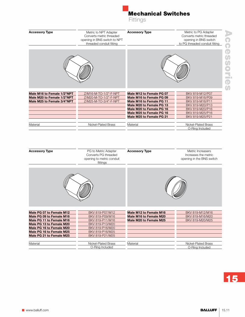
Metric to PG AdapterConverts metric threaded opening in BNS switch
to PG threaded conduit fiiting
BKV 819-M12/P07 BKV 819-M16/P09 BKV 819-M16/P11 BKV 819-M20/P13 BKV 819-M20/P16 BKV 819-M25/P16 BKV 819-M25/P21
Nickel-Plated BrassO-Ring Included
Accessory Type
Male M12 to Female PG 07Male M16 to Female PG 09Male M16 to Female PG 11Male M20 to Female PG 13Male M20 to Female PG 16Male M25 to Female PG 16Male M25 to Female PG 21
Material
Metric to NPT AdapterConverts metric threaded
opening in BNS switch to NPT threaded conduit fiiting
Z/M16-M-TO-1/2"-F-NPT Z/M20-M-TO-1/2"-F-NPT Z/M25-M-TO-3/4"-F-NPT
Nickel-Plated Brass
Accessory Type
Male M16 to Female 1/2"NPTMale M20 to Female 1/2"NPTMale M25 to Female 3/4"NPT
Material
PG to Metric AdapterConverts PG threaded
opening to metric conduit fittings
BKV 819-P07/M12 BKV 819-P09/M16 BKV 819-P11/M16 BKV 819-P13/M20 BKV 819-P16/M20 BKV 819-P16/M25 BKV 819-P21/M25
Nickel-Plated Brass O-Ring Included
Metric IncreasersIncreases the metric
opening in the BNS switch
BKV 819-M12/M16 BKV 819-M16/M20 BKV 819-M20/M25
Nickel-Plated BrassO-Ring Included
Accessory Type
Male M12 to Female M16Male M16 to Female M20Male M20 to Female M25
Material
Accessory Type
Male PG 07 to Female M12Male PG 09 to Female M16Male PG 11 to Female M16Male PG 13 to Female M20Male PG 16 to Female M20Male PG 16 to Female M25Male PG 21 to Female M25
Material
Fittings

Mechanical Switches
15.12
Cord Seal Metric threads
Viton form seal and O-ring150 PSI
BKV 820-M12/2-5-01-MBKV 820-M16/4-8-01-M BKV 820-M16/5-10-03-MBKV 820-M20/7-12-01-MBKV 820-M20/10-14-01-M BKV 820-M25/9-16-01-MBKV 820-M25/13-18-01-MBKV 820-M32/13-20-01-M
Nickel-Plated BrassPVDF Spline Bushing
Accessory Type
Male M16 to Female M12Male M20 to Female M12Male M20 to Female M16Male M25 to Female M16Male M25 to Female M20
Material
Metric ReducersDecreases the metric opening
in the BNS switch
BKV 819-M16/M12BKV 819-M20/M12 BKV 819-M20/M16 BKV 819-M25/M16 BKV 819-M25/M20
Nickel-Plated BrassO-Ring Included
Accessory Type
M12 Cable Range 2 - 5 mmM16 Cable Range 4 - 8 mmM16 Cable Range 5-10 mmM20 Cable Range 7 - 12 mmM20 Cable Range 10 - 14 mmM25 Cable Range 9 - 16 mmM25 Cable Range 13 - 18 mmM32 Cable Range 13 - 20 mm
Material
Accessory Type
M16 Plastic CapM20 Plastic CapM25 Plastic Cap
Material
Sealing CapPlastic metric threaded
sealing cap Supplied with O-Ring
VERSCHLUSSSCHR. KPL. M16X1,5VERSCHLUSSSCHR. KPL. M20X1,5VERSCHLUSSSCHR. KPL. M25X1,5
PlasticO-Ring Included
Accessory Type
BSE-85 ElementsBSE-30 & BSE 61 ElementsInductive Switches with 3.2 mmassured sensing distance
Material
BNS Set Up GaugeUsed to set distance
between BNSswitch face and cams
BNL Z/GAUGE-X508BNL GAUGE-100-3MMGAGE BAM-AC-NS 127.
x25.4x1.60 ALU
SteelAluminum
Accessory Type
D - Rigid Chisel Plunger (813 or 823) - SafetyD - Telescoping Chisel Plunger (819 or 829) - StandardK - Rigid Ball Plunger (813 or 823) - SafetyK - Telescoping Ball Plunger (819 or 829) - StandardL - Rigid Roller Bearing Plunger (813 or 823) - SafetyL - Telescoping Roller Bearing Plunger (819 or 829) - StandardR - Rigid Roller Plunger (813 or 823) - SafetyR - Telescoping Roller Plunger (819 or 829) - Standard
Replacement PlungersStainless steel plungers
Telescoping style for standard switches
Rigid style for safety switches
STOESSELEINHEIT KPL. D10 813STOESSELEINHEIT KPL. D10 819STOESSELEINHEIT KPL. K10 813STOESSELEINHEIT KPL. K10 819STOESSELEINHEIT KPL. L10 813STOESSELEINHEIT KPL. L10 819STOESSELEINHEIT KPL. R10 813STOESSELEINHEIT KPL. R10 819
Fittings

Mechanical Switches
15.13n www.balluff.com
Accesso
ries
15
Accessory Type
Wiper Plate10 mm plunger8 mm plunger
Replacement Wiper Plate includes plate and mounting screws
ABSTREIFPLATTE KPL. F. STOESSEL E10 NEUABSTREIFPLATTE KPL. F. STOESSEL E6 NEU
Accessory Type
4 position 61 series6 position 61 series4 position 100 series6 position 100 series
Brush Replacement Kits4 position brush6 position brush
Brush Holder and Brush Replacement Kits4 position6 position
BNS Protection Cover for 4 and 6 Position 61 and 100 SeriesProvide additional protection for mechanical and inductive
switches in harsh environments. Brass brushes rub against cams to help remove foreign debris.
BAM SH-NS-61-V1-04BAM SH-NS-61-V1-06BAM SH-NS-100-V1-04BAM SH-NS-100-V1-06
BAM SH-NS-V1-RK2-48mmBAM SH-NS-V1-RK2-72mm
BAM SH-NS-V1-RK1-48mmBAM SH-NS-V1-RK1-72mm
Accessories

Mechanical Switches
15.14
BNS Switches With Number of Pre-Wired Connectors
X#### Unique Part Number Assigned By Factory Number of Connectors Required
Switch Housing Series
Connector Suffix Connector Description
Number of Switch Positions
2 3 4 5 6 8 10 12
40 / 650-11 Series S80 5 Pole Dual Keyway Connector without LED 1 1 2 2 2
S80 5 Pole Dual Keyway Connector with LED 1 2 2
S72 5 Pole Center Pin Ground Connector without LED 1 1 2 2 2
S72 5 Pole Center Pin Ground Connector with LED 1 2 2
X #### 8 Pole Connector without LED 1 1 1 1 1
X #### 8 Pole Connector with LED 1 1 1 1 2
X #### 9 Pole Connector without LED 1 1 1 1 1
X #### 9 Pole Connector with LED 1 1 1 1 2
S90 12 Pole Connector without LED 1 1 1 1 1
S90 12 Pole Connector with LED 1 1 1 1 1
46 / 603-11 Series S80 5 Pole Dual Keyway Connector without LED 1 1 2 2 2
S80 5 Pole Dual Keyway Connector with LED 1 2 2
S72 5 Pole Center Pin Ground Connector without LED 1 1 2 2 2
S72 5 Pole Center Pin Ground Connector with LED 1 2 2
X #### 8 Pole Connector without LED 1 1 1 1 1 2 2
X #### 8 Pole Connector with LED 1 1 1 1 2 2 2
X #### 9 Pole Connector without LED 1 1 1 1 1 2 2
X #### 9 Pole Connector with LED 1 1 1 1 2 2 2
S90 12 Pole Connector without LED 1 1 1 1 1 1 1
S90 12 Pole Connector with LED 1 1 1 1 1 2 2
61 / 610-11 / 611-11 / 612-11 / 613-11 Series
S80 5 Pole Dual Keyway Connector without LED 1 1 2 2 2
S80 5 Pole Dual Keyway Connector with LED 1 2 2
S72 5 Pole Center Pin Ground Connector without LED 1 1 2 2 2
S72 5 Pole Center Pin Ground Connector with LED 1 2 2
X #### 8 Pole Connector without LED 1 1 1 1 1
X #### 8 Pole Connector with LED 1 1 1 1 2
X #### 9 Pole Connector without LED 1 1 1 1 1
X #### 9 Pole Connector with LED 1 1 1 1 2
S90 12 Pole Connector without LED 1 1 1 1 1
S90 12 Pole Connector with LED 1 1 1 1 1
X #### 19 Pole Connector without LED 1 1 1 1 1
X #### 19 Pole Connector with LED 1 1 1 1 1
X#### 24 Pin Harting DD Connector with LED 1 1 1 1 1
X#### 24 Pin Harting DD Connector without LED 1 1 1 1 1
X#### 32 Pin Harting EE Connector with LED 1 1 1 1 1
X#### 32 Pin Harting EE Connector without LED 1 1 1 1 1
Accessories - Pre-wired Connectors
Mechanical Switches
15.15n www.balluff.com
Accesso
ries
15
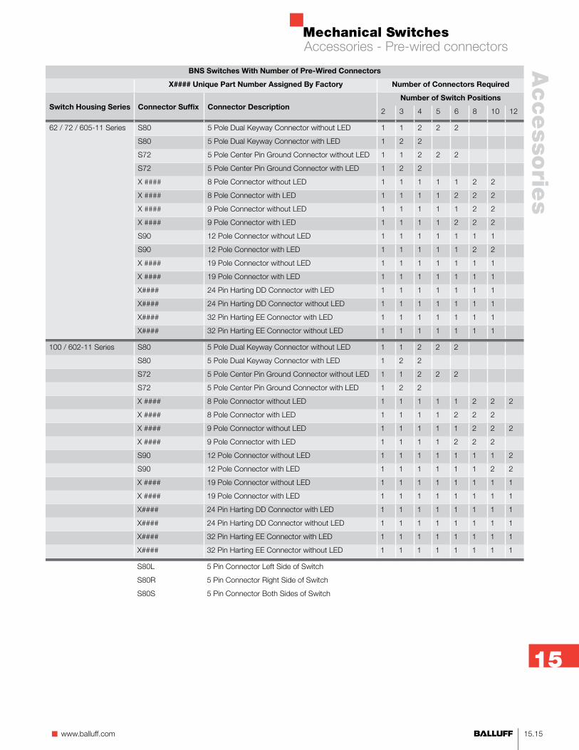
BNS Switches With Number of Pre-Wired Connectors
X#### Unique Part Number Assigned By Factory Number of Connectors Required
Switch Housing Series
Connector Suffix
Connector Description
Number of Switch Positions
2 3 4 5 6 8 10 12
62 / 72 / 605-11 Series S80 5 Pole Dual Keyway Connector without LED 1 1 2 2 2
S80 5 Pole Dual Keyway Connector with LED 1 2 2
S72 5 Pole Center Pin Ground Connector without LED 1 1 2 2 2
S72 5 Pole Center Pin Ground Connector with LED 1 2 2
X #### 8 Pole Connector without LED 1 1 1 1 1 2 2
X #### 8 Pole Connector with LED 1 1 1 1 2 2 2
X #### 9 Pole Connector without LED 1 1 1 1 1 2 2
X #### 9 Pole Connector with LED 1 1 1 1 2 2 2
S90 12 Pole Connector without LED 1 1 1 1 1 1 1
S90 12 Pole Connector with LED 1 1 1 1 1 2 2
X #### 19 Pole Connector without LED 1 1 1 1 1 1 1
X #### 19 Pole Connector with LED 1 1 1 1 1 1 1
X#### 24 Pin Harting DD Connector with LED 1 1 1 1 1 1 1
X#### 24 Pin Harting DD Connector without LED 1 1 1 1 1 1 1
X#### 32 Pin Harting EE Connector with LED 1 1 1 1 1 1 1
X#### 32 Pin Harting EE Connector without LED 1 1 1 1 1 1 1
100 / 602-11 Series S80 5 Pole Dual Keyway Connector without LED 1 1 2 2 2
S80 5 Pole Dual Keyway Connector with LED 1 2 2
S72 5 Pole Center Pin Ground Connector without LED 1 1 2 2 2
S72 5 Pole Center Pin Ground Connector with LED 1 2 2
X #### 8 Pole Connector without LED 1 1 1 1 1 2 2 2
X #### 8 Pole Connector with LED 1 1 1 1 2 2 2
X #### 9 Pole Connector without LED 1 1 1 1 1 2 2 2
X #### 9 Pole Connector with LED 1 1 1 1 2 2 2
S90 12 Pole Connector without LED 1 1 1 1 1 1 1 2
S90 12 Pole Connector with LED 1 1 1 1 1 1 2 2
X #### 19 Pole Connector without LED 1 1 1 1 1 1 1 1
X #### 19 Pole Connector with LED 1 1 1 1 1 1 1 1
X#### 24 Pin Harting DD Connector with LED 1 1 1 1 1 1 1 1
X#### 24 Pin Harting DD Connector without LED 1 1 1 1 1 1 1 1
X#### 32 Pin Harting EE Connector with LED 1 1 1 1 1 1 1 1
X#### 32 Pin Harting EE Connector without LED 1 1 1 1 1 1 1 1
S80L 5 Pin Connector Left Side of Switch
S80R 5 Pin Connector Right Side of Switch
S80S 5 Pin Connector Both Sides of Switch
Accessories - Pre-wired connectors

Mechanical Switches
15.16
Mini Size A3 pole
Straight Male
R05 CA-03-L-18C-010F
300 Vac/Vdc8 Amps18 AWG
PVCanodized aluminum
vitonIP 67
-40 to 194°Fyes
Mini Size A4 pole
Straight Male
R05 CA-04-L-18C-010F
300 Vac/Vdc5 Amps18 AWG
PVCanodized aluminum
vitonIP 67
-40 to 194°Fyes
Mini Size A5 pole
Straight Male
R0A CA-05-L-18C-010F
300 Vac/Vdc5 Amps18 AWG
PVCanodized aluminum
vitonIP 67
-40 to 194°Fyes
Micro DCM12 - 4 poleStraight Male
R04 CA-04-L-22A-010F
300 Vac/Vdc4 Amps22 AWG
PVCnickel plated brass
vitonIP 67
-40 to 221°Fyes
Micro AC 1/2"x20 UNFMicro AC - 3 pole
Straight Male
R21 CA-03-K-22B-010F
300 Vac/Vdc4 Amps22 AWG
PVCanodized aluminum
vitonIP 67
-4 to 221°Fyes
Micro AC 1/2"x20 UNFMicro AC - 3 pole
Straight Male
R21 CA-03-L-22B-010F
300 Vac/Vdc4 Amps22 AWG
PVCanodized aluminum
vitonIP 67
-4 to 221°Fyes
Connector StyleConfiguration
M16 x 1.5 Fig. 1M20 x 1.5 Fig. 2
Voltage RatingAmperageWire GaugeJacketShellO-ringProtectionAmbient Operating Temp.cULus Recognized
Micro DCM12 - 4 poleStraight Male
R04 CA-04-K-22A-010F
300 Vac/Vdc4 Amps22 AWG
PVCnickel plated brass
vitonIP 67
-40 to 221°Fyes
ConnectorStyleConfiguration
M20 x 1.5 Fig. 3
Voltage RatingAmperageWire GaugeJacketShellO-ringProtectionAmbient Operating Temp.cULus Recognized
1 Brown2 White3 Blue4 Black
1 Brown2 White3 Blue4 Black
1 Green/Yellow2 Red/Black Tr.3 Red/White Tr.
1 Green/Yellow2 Red/Black Tr.3 Red/White Tr.
24.6
13.7
25.4 HEX
1 FOOT
M16 x 1.5
O-RING
M12 x 1 (DC)½” x 20 (AC)
Fig. 1 (Male)
1 Black2 White3 Red4 Green/Yellow
1 White2 Red3 Green/Yellow4 Orange5 Black
24.6
13.7
25.4 HEX
1 FOOT
M20 x 1.5
O-RING
M12 x 1 (DC)½” x 20 (AC)
Fig. 2 (Male)
7/8” - 16UN-2A
23.1
17.3
25.4
1 FOOT
M20 x 1.5
O-RING
Fig. 3 (Male)
1 Black2 White3 Red
Connectors

Mechanical Switches
15.17n www.balluff.com
Accesso
ries
15
Mini Size C19 Pole
Straight Male
BCC A55L-0000-20-RM046-003
300 V4 Amps
3/18 & 16/22 AWGPVC
clear anodized aluminumvitonIP 67
-4 to 221°Fyes
ConnectorStyleConfiguration
M20 x 1.5 Fig. 5
Voltage RatingAmperageWire GaugeJacketShellO-ringProtectionAmbient Operating Temp.cULus Recognized
Mini Size C9 pole
Straight Male
BCC A559-0000-20-RM041-003
300 Vac/Vdc4 Amps18 AWG
PVCanodized aluminum
vitonIP 67
-4 to 221°Fyes
Mini Size C10 pole
Straight Male
BCC A55A-0000-20-RM043-003
300 Vac/Vdc4 Amps18 AWG
PVCanodized aluminum
vitonIP 67
-4 to 221°Fyes
Mini Size C12 pole
Straight Male
BCC A55C-0000-20-RM044-003
300 Vac/Vdc4 Amps18 AWG
PVCanodized aluminum
vitonIP 67
-4 to 221°Fyes
ConnectorStyleConfiguration
M20 x 1.5 Fig. 4
Voltage RatingAmperageWire GaugeJacketShellO-RingProtectionAmbient Operating Temp.cULus Recognized
Mini Size B6 pole
Straight Male
R0B CA-06-L-18C-010F
300 Vac/Vdc5 Amps18 AWG
PVCanodized aluminum
vitonIP 67
-40 to 221°Fyes
Mini Size B7 pole
Straight Male
R0B CA-07-L-18C-010F
300 Vac/Vdc5 Amps18 AWG
PVCanodized aluminum
vitonIP 67
-40 to 221°Fyes
Mini Size B8 pole
Straight Male
R0B CA-08-L-18C-010F
300 Vac/Vdc5 Amps18 AWG
PVCanodized aluminum
vitonIP 67
-40 to 221°Fyes
1 Orange2 Blue3 Black4 White5 Red6 Green/Yellow
1 White/Black Tr.2 Black3 White4 Red5 Orange6 Blue7 Green/Yellow
1 Orange2 Blue3 White/Black Tr.4 Black5 White6 Red7 Green/Yellow8 Red/Black Tr.
Fig. 4 (Male)
6 Orange/Black 7 Red 8 Green/Yellow 9 Black 10 White
7 Blue/Black8 Black/White9 Green/Yellow10 Red 11 White12 Black
1 Orange2 Blue3 White/Black4 Red/Black5 Green/Black6 Orange/Black
1 Orange2 Blue3 Red/Black4 Green/Black5 White
6 Red7 Green/Yellow8 White/Black9 Black
1 Orange2 Blue3 White/Black4 Red/Black5 Green/Black
1-1/8”-16UN-2A
31.8
29.25.8
O-RING
M20 x1.5 THREADS
1 FOOT
Fig. 5 (Male)
1218 1
2
3
8
17
16
7615 5
4
9
10
11
13
19
14
1 Violet2 Red3 Gray4 Red/Blue5 Blue6 Green7 Brown8 White/Green
9 White/Yellow10 White/Gray11 Black12 Green/Yellow13 Yellow/Brown14 Brown/Green15 Gray/Pink
1-1/8”-16UN-2A
31.8
29.27.4
O-RING
M25 x1.5 THREADS
1 FOOT
*Fig. 5 (Male)
Connectors

Mechanical Switches
15.18
MicroM12 DC Single KeywayRight Angle Female
BCC M425-0000-1A-001-VX43T2-XXXBCC M425-0000-1A-001-EX432T2-XXXBCC M425-0000-1A-003-VX44T2-XXXBCC M425-0000-1A-003-EX44T2-XXXC04 BEQ-00-VY-050M
250 Vac/Vdc (36 Vdc–8 wire)4 Amps22 AWG (24 AWG– 8 wire)Yellow PVC, TPE (PUR–8 wire)Black Epoxy Coated ZincIP 67-5° C to 105° C yesyes
ConnectorStyleConfiguration
3 Wire PVC3 Wire TPE4 Wire PVC4 Wire TPE5 Wire, non-LED
Voltage Rating (non-LED)AmperageWire GaugeJacketCoupling Nut *8-pole Nickel Plated BrassProtectionAmbient Operating TemperatureUL ListedCSA Certified
MicroM12 DC Single KeywayStraight Female
BCC M415-0000-1A-001-VX43T2-XXXBCC M415-0000-1A-001-EX43T2-XXXBCC M415-0000-1A-003-VX44T2-XXXBCC M415-0000-1A-003-EX44T2-XXXC04 AEQ-00-VY-050M
250 Vac/Vdc (36 Vdc-8 wire)4 Amps22 AWG (24 AWG-8 wire)Yellow PVC, TPE (PUR-8 wire)Black Epoxy Coated ZincIP 67-5° C to 105° Cyesyes
Notes: 1. 5 meter cable length is standard (other lengths available - consult factory) 2. Additional cable options are available from the part matrix. Consult factory for availability. Minimum order quantities and lead times may apply.
Female 2-5 pin face view
2
1 3
4
5
3-wirePin # Color 1 Brown 2 3 Blue 4 Black 5
4-wirePin # Color 1 Brown 2 White 3 Blue 4 Black 5
5-wire Pin # Color 1 Brown 2 White 3 Blue 4 Black 5 Grey
14.5
Length
47
M12x1
31
M12x1
Length
31
14.5
Cables

Mechanical Switches
15.19n www.balluff.com
Accesso
ries
15
ConnectorVersionUse
12-pin5-pin4-pin3-pin
Supply voltage UB
CableNo. of wires × AWGDegree of protection per IEC 60529Ambient temperature range Ta
View of female side
BKS-S 80Straight femaleBNS ...-S80
BKS-S 80-G-PU-05
300 V AC/10...60 V DC5 m molded-on PUR5×20IP 67–25...+90 °C
BKS-S 80Right angle femaleBNS ...-S80
BKS-S 80-W-PU-05
300 V AC/10...60 V DC5 m molded-on PUR5×20IP 68 per BWN Pr. 20–25...+90 °C
Cables
Mechanical Switches
15.20
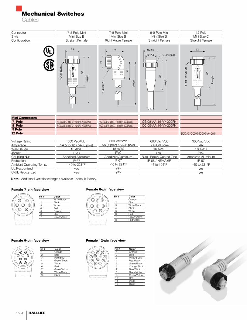
12 PoleMini Size C
Straight Female
BCC A51C-0000-10-090-VX4CW8-_ _ _
300 Vac/Vdc4A
18 AWGPVC
Anodized AluminumIP 67
-40 to 221°Fyesyes
7-8 Pole MiniMini Size B
Straight Female
BCC A417-0000-10-086-VX47W8-_ _ _BCC A418-0000-10-087-VX48W8-_ _ _
300 Vac/Vdc5A (7 pole) / 5A (8 pole)
18 AWGPVC
Anodized AluminumIP 67
-40 to 221°Fyesyes
7-8 Pole MiniMini Size B
Right Angle Female
BCC A427-0000-10-086-VX47W8-_ _ _BCC A428-0000-10-087-VX48W8-_ _ _
300 Vac/Vdc5A (7 pole) / 5A (8 pole)
18 AWGPVC
Anodized AluminumIP 67
-40 to 221°Fyesyes
ConnectorStyleConfiguration
Mini Connectors 7 Pole 8 Pole 9 Pole12 Pole
Voltage RatingAmperageWire GaugeJacketCoupling NutProtectionAmbient Operating Temp.UL RecognizedC-UL Recognized
8-9 Pole MiniMini Size B
Straight Female
CB 08-AA-16-VY-200FHCC 09-AA-16-VY-200FH
600 Vac/Vdc 7A (8/9 pole)
16 AWGPVC
Black Epoxy Coated ZincIP 68 / NEMA 6P
-4 to 194°F
1”-16UN-2B
29
58
Length
1”-16UN-2B
38
29
45
Length
1”-1/8”-16UN-2B
32
65
Length
Note: Additional variations/lengths available - consult factory.
Female 8-pin face view Pin # Color 1 Orange 2 Blue 3 White/Black 4 Black 5 White 6 Red 7 Green/Yellow 8 Red/Black
7
8
4
6
3
2
1
5
Female 12-pin face view
9
11
5
12
6
7
8
4
10
3
2
1
Female 7-pin face view Pin # Color 1 White/Black 2 Black 3 White 4 Red 5 Orange 6 Blue 7 Green/Yellow
7
4
6
3
2
1
5
Pin # Color 1 Orange 2 Blue 3 White/Black 4 Red/Black 5 Green/Black 6 Orange/Black 7 Blue/Black 8 Black/White 9 Green/Yellow 10 Red 11 White 12 Black
Cables
Female 9-pin face view
Pin # Color 1 Orange 2 Blue 3 Red/Black 4 Green/Black 5 White 6 Red 7 Green/Yellow 8 White/Black 9 Black
2
1
4
5
3
6
7
89
Ø28.5
68
Length
Ø17.6 1”-16” UN-2B
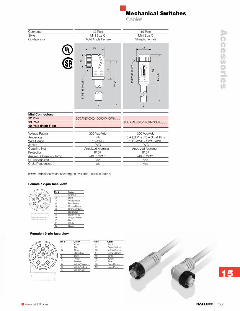
Mechanical Switches
15.21n www.balluff.com
Accesso
ries
15
ConnectorStyleConfiguration
Mini Connectors12 Pole19 Pole19 Pole (High Flex)
Voltage RatingAmperageWire GaugeJacketCoupling NutProtectionAmbient Operating Temp.UL RecognizedC-UL Recognized
19 PoleMini Size C
Straight Female
BCC A51L-0000-10-091-PX0LW8-_ _ _
300 Vac/Vdc8 A LG Pins / 3 A Small Pins
18/3 AWG / 22/16 AWGPVC
Anodized AluminumIP 67
-40 to 221°Fyesyes
12 PoleMini Size C
Right Angle Female
BCC A52C-0000-10-090-VX4CW8-_ _ _
300 Vac/Vdc4A
18 AWGPVC
Anodized AluminumIP 67
-40 to 221°Fyesyes
35
32
45
Length
1”-1/8”-16UN-2B 1”-1/8”-16UN-2B
32
65
Length
Female 12-pin face view
9
11
5
12
6
7
8
4
10
3
2
1
Pin # Color 1 Orange 2 Blue 3 White/Black 4 Red/Black 5 Green/Black 6 Orange/Black 7 Blue/Black 8 Black/White 9 Green/Yellow 10 Red 11 White 12 Black
Note: Additional variations/lengths available - consult factory.
Cables
Female 19-pin face view
Pin # Color 1 Violet 2 Red 3 Grey 4 Red/Blue 5 Blue 6 Green 7 Brown 8 White/Green 9 White/Yellow 10 White/Grey
Pin # Color 11 Black 12 Green/Yellow 13 Yellow/Brown 14 Brown/Green 15 White 16 Yellow 17 Pink 18 Grey/Brown 19 Grey/Pink
19
12
6
15
5
1
2
3
4
14
13
16
7
11
10
9
8
17
18

Mechanical Switches
15.22
BKS-B 20Right angle femaleBNS ...-S4_-I (IO-Link)
BCC M425-0000-1A-001-VX8334-_ _ _
10...30 V DC3 m molded PVC3×0.34 mm²IP 67–25...+85 °C
BKS-S 19Straight femaleBNS ...-S4_-I (IO-Link)
BCC M415-0000-1A-003-PX0434-_ _ _BCC M415-0000-1A-001-PX0334-_ _ _
10...30 V DC3 m molded PUR3×0.34 mm²/4×0.34 mm²IP 68 per BWN Pr. 20–25...+70 °C
BKS-B 19Straight femaleBNS ...-S4_-I (IO-Link)
BCC M415-0000-1A-003-VX8434-_ _ _BCC M415-0000-1A-001-VX8334-_ _ _
10...30 V DC3 m/5 m molded-on PVC3×0.34 mm²/4×0.34 mm²IP 67–25...+85 °C
ConnectorVersionUse
4-pin3-pin
Supply voltage UB
CableNo. of wires × cross-sectionDegree of protection per IEC 60529Ambient temperature range Ta
Note!
Standard configuration Is normally open. Other pin assignments on request.
If there are multiple switch positions, multiple connectors or larger connectors with a larger number of pins are used.
Other cable lengths on request.
IO-Link Cables
IO-Link

Mechanical Switches
15.23n www.balluff.com
Accesso
ries
15
ConnectorVersionUse
Part number
HousingInsertContactsWire sizeJacketVoltage ratingNumber of conductorsTemperature
Harting 24-pin DDRight angle with flying leadsBNS with 24-pin connector
BKS-X518-CABLE-10FTBKS-X518-CABLE-20FTBKS-X518-CABLE-25FTBKS-X518-CABLE-30FTBKS-X518-CABLE-40FTBKS-X518-CABLE-50FTBKS-X518-CABLE-65FTBKS-X518-CABLE-75FTBKS-X518-CABLE-85FTBKS-X518-CABLE-100FT
24 DD right angle24 DD female
Silver plated female sockets18 AWG
PVC, Gray600 VAC/VDC
25-5°...90°C
Harting 24-pin DDRight angle with flying leads hi-flex
BNS with 24-pin connector
BKS-X518-CABLE-HI-FLEX-15FTBKS-X518-CABLE-HI-FLEX-20FTBKS-X518-CABLE-HI-FLEX-30FTBKS-X518-CABLE-HI-FLEX-40FTBKS-X518-CABLE-HI-FLEX-60FTBKS-X518-CABLE-HI-FLEX-100FTBKS-X518-CABLE-HI-FLEX-120FT
24 DD right angle24 DD female
Silver plated female sockets16 AWG
TPE, Yellow600 VAC/VDC
31-5°...90°C
Notes:- Pin 1 bottom left when facing connector- Wired straight through (wire 1 on PIN 1)
Harting Cables

Mechanical Switches
15.24
Notes:- Pin 1 bottom left when facing connector- Wired straight through (wire 1 on PIN 1)
ConnectorVersionUse
Part number
HousingInsertContactsWire sizeJacketVoltage ratingNumber of conductorsTemperature
Harting 24-pin DDRight angle/straight double ended
BNS with 24-pin connector
BKS-X518-CABLE-EXTENSION-020FTBKS-X518-CABLE-EXTENSION-040FTBKS-X518-CABLE-EXTENSION-050FTBKS-X518-CABLE-EXTENSION-060FTBKS-X518-CABLE-EXTENSION-080FTBKS-X518-CABLE-EXTENSION-095FT
Right angle female/straight male24 DD female/24 DD male
Silver plated female sockets/male pins18 AWG
PVC, Gray600 VAC/VDC
25-5°...90°C
Harting Cables

Mechanical Switches
15.25n www.balluff.com
Accesso
ries
15
Harting Cables
Notes:- Pin 1 bottom left when facing connector- Wired straight through (wire 1 on PIN 1)
ConnectorVersionUse
Part number
HousingInsertContactsWire sizeJacketVoltage ratingNumber of conductorsTemperature
Harting 32-pin EERight angle with flying leadsBNS with 32-pin connector
BKS-X524-CABLE-40FT
32 EE right angle32 EE female
Silver plated female sockets18 AWG
PVC, Gray600 VAC/VDC
25-5°...90°C
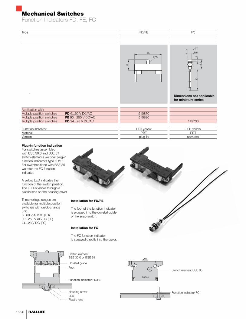
Mechanical Switches
15.26
Type
Application withMultiple position switches FD 6...60 V DC/ACMultiple position switches FE 90...250 V DC/ACMultiple position switches FD 24...28 V DC/AC
Function indicatorMaterialVersion
FC
149730
LED yellowPBT
universal
FD/FE
510870510880
LED yellowPBT
plug-in
Plug-in function indication For switches assembled with BSE 30.0 and BSE 61 switch elements we offer plug-in function indicators type FD/FE. For switches fitted with BSE 85 we offer the FC function indicator. A yellow LED indicates the function of the switch position. The LED is visible through a plastic lens on the housing cover. Three voltage ranges are available for multiple position switches with quick-change unit:6...60 V AC/DC (FD)90...250 V AC/DC (FE)24...28 V DC (FC)
Switch element BSE 30.0 or BSE 61
Dovetail guide
Function indicator FD/FE
Housing cover
Installation for FD/FE
The foot of the function indicator is plugged into the dovetail guide of the snap switch.
Installation for FC
The FC function indicator is screwed directly into the cover.
Foot
LEDPlastic lens
Switch element BSE 85
Function indicator FC
Dimensions not applicable for miniature series
Function Indicators FD, FE, FC