LINE FOLLOWING ROBOT - Techkritim.techkriti.org/Initiatives/Robogames/iARC tutorial.pdf · Line...
10
2014 Techkriti’14 LINE FOLLOWING ROBOT Tutorial for iARC LINE FOLLOWING ROBOT
Transcript of LINE FOLLOWING ROBOT - Techkritim.techkriti.org/Initiatives/Robogames/iARC tutorial.pdf · Line...

2014
Techkriti’14
LINE FOLLOWING ROBOT
Tutorial for iARC
LINE FOLLOWING ROBOT
INTRODUCTION
Line following Robot is a machine that can follow a path. The path can be visible like a black
line on a white surface (or vice-versa) or it can be invisible like a magnetic field.
Sensing a line and maneuvering the robot to stay on course, while constantly correcting
wrong moves using feedback mechanism forms a simple yet effective closed loop system. As
a programmer you get an opportunity to ‘teach’ the robot how to follow the line thus giving it
a human-like property of responding to stimuli.
Practical applications of a line follower: Automated cars running on roads with embedded
magnets; guidance system for industrial robots moving on shop floor etc.
Knowledge of basic digital and electronics.
C Programming.
Sheer interest, an innovative brain and perseverance!
In this tutorial, we will learn how to make a line following robot using
Arduino as the processing unit.
MATERIALS The materials list for a Line Following Robot is pretty basic and straightforward:
This is going to be the main processing unit for our robot. All the logic
operations will be performed by arduino. Besides, it will do the work of ‘commanding’
all other components to start/stop their work.
All motors are directly connected to the motor driver.
Motor driver receives command from the microcontroller in form of PWM signals
and accordingly drives the motors at varying speed.
Obviously, we would be needing the motors as the main actuators for our
robot.
This would the main input sources for ‘feedback’ on the
whereabouts of the robot with respect to the line. We can use any number of sensors
in the array but generally, we use 5 or 7 sensor array plate.
We are going to need a 12V external power supply/battery
as the main power source for our battery.
The construction of the body of the robot using the above materials is straight forward and I
leave it upon you to build a basic robot to work with. I recommend you to go through the
whole tutorial before you begin to build the robot. Don’t make any decisions regarding the
arrangement of any component on the robot if you are not sure about the working of the
components.
Consider various possible arrangements of the components.
Think about the possible merits and demerits of each arrangement with respect to
response time available for actuators to react, required difference in speed of the two
actuators for a particular turn, difficulty of operating algorithm etc.
And of course, GOOGLE is always there!
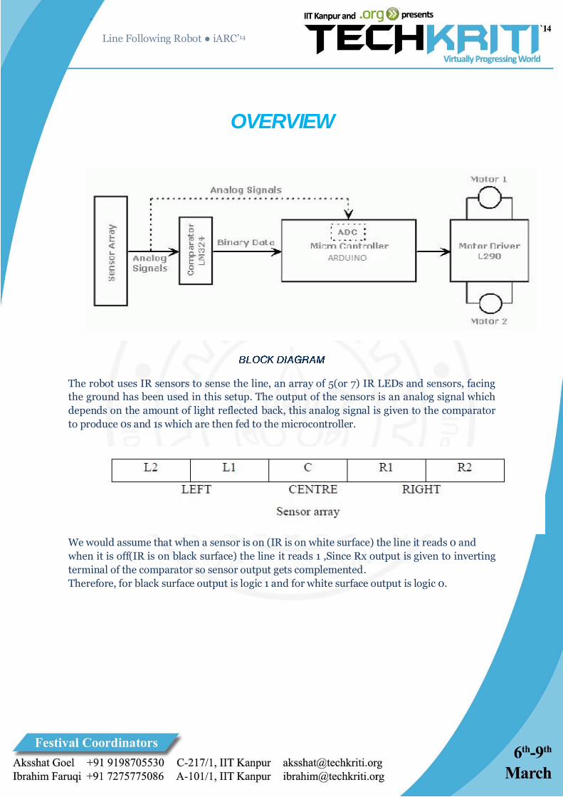
OVERVIEW
The robot uses IR sensors to sense the line, an array of 5(or 7) IR LEDs and sensors, facing
the ground has been used in this setup. The output of the sensors is an analog signal which
depends on the amount of light reflected back, this analog signal is given to the comparator
to produce 0s and 1s which are then fed to the microcontroller.
We would assume that when a sensor is on (IR is on white surface) the line it reads 0 and
when it is off(IR is on black surface) the line it reads 1 ,Since Rx output is given to inverting
terminal of the comparator so sensor output gets complemented.
Therefore, for black surface output is logic 1 and for white surface output is logic 0.

ALGORITHM
Consider Line Following using two motors.
Simplest line following algorithm simply looks to see if the robot is to the right or left of the
line.
1. If the robot is to the right of the line, the left motor stops and the right motor speeds up.
2. If the robot is to the left of the line, the left motor speeds up and the right motor
stops.
This gets the job done. But the robot tends to move in a ‘zig-zag’ path. The maximum speed
achieved by this algorithm is less compared to what can be achieved by a PID based
algorithm. Also line following on turns is unreliable unless the robot is slowed down.
A better implementation of this algorithm would be to calculate the deviation of the robot
from the line. Then increase or decrease the motor speeds proportional to the deviation
e.g.-the deviation ranges between -3 to +3.
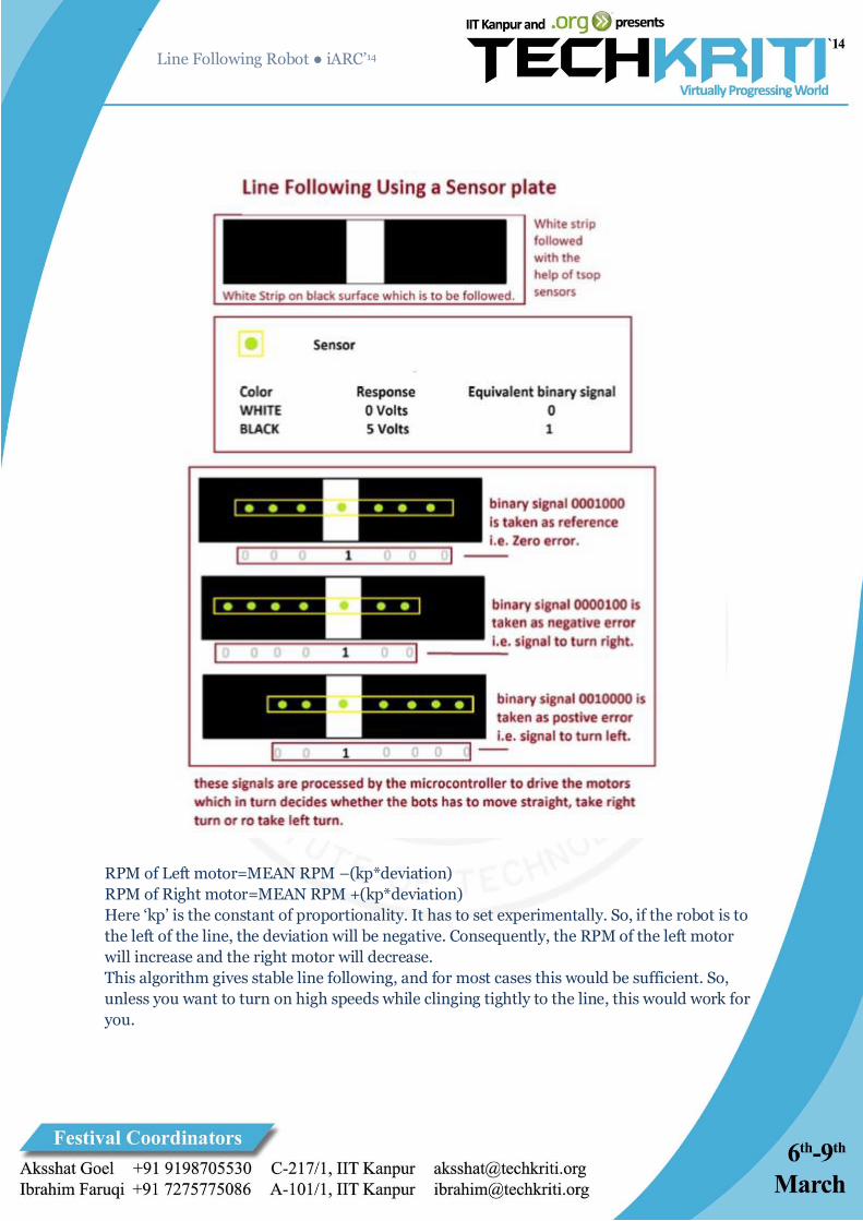
RPM of Left motor=MEAN RPM –(kp*deviation)
RPM of Right motor=MEAN RPM +(kp*deviation)
Here ‘kp’ is the constant of proportionality. It has to set experimentally. So, if the robot is to
the left of the line, the deviation will be negative. Consequently, the RPM of the left motor
will increase and the right motor will decrease.
This algorithm gives stable line following, and for most cases this would be sufficient. So,
unless you want to turn on high speeds while clinging tightly to the line, this would work for
you.

This has 2 problems-
1. If the robot is not responsive enough it will return back slowly to the mean position even
after deviation is detected .
2. Now, you may want to increase the constant of proportionality, so that the return to mean
position is faster. But this would mean that when the robot reaches the mean position it will
tend to overshoot it due to inertia-cross to the other side-return back with a high speed-then
over shoot again. Resulting in a zig–zag path.
A proportional–integral–derivative controller (PID controller) is a generic feedback
controller. It can be used whenever a mean position has to be achieved but the controls of the
system do not react instantaneously and accurately.
The PID algorithm, takes in account the following 3 things- the existing error, the time the
system has stayed away from the mean position and the possibility of overshooting the mean
position. Using these 3 quantities, the system is controlled better, allowing it to reach the
mean position faster and without over shooting it.
Two terms before we use PID for line following-
Correction - The term that is added and subtracted to the mean RPMs of the motors.
Deviation – The deviation of the robot from the line. It is negative when the robot is to the
left of the line and positive when it’s to the right.
PID is used to calculate the ‘correction’ term.
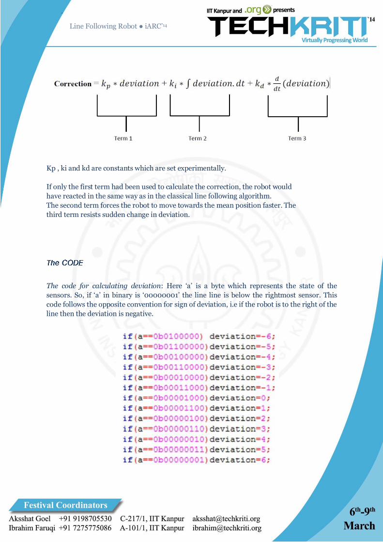
Kp , ki and kd are constants which are set experimentally.
If only the first term had been used to calculate the correction, the robot would
have reacted in the same way as in the classical line following algorithm.
The second term forces the robot to move towards the mean position faster. The
third term resists sudden change in deviation.
The code for calculating deviation: Here ‘a’ is a byte which represents the state of the
sensors. So, if ‘a’ in binary is ‘00000001’ the line line is below the rightmost sensor. This
code follows the opposite convention for sign of deviation, i.e if the robot is to the right of the
line then the deviation is negative.
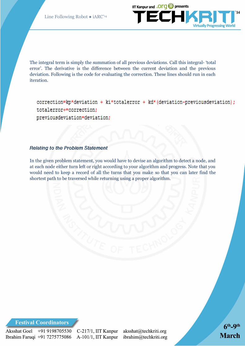
The integral term is simply the summation of all previous deviations. Call this integral- ‘total
error’. The derivative is the difference between the current deviation and the previous
deviation. Following is the code for evaluating the correction. These lines should run in each
iteration.
In the given problem statement, you would have to devise an algorithm to detect a node, and
at each node either turn left or right according to your algorithm and progress. Note that you
would need to keep a record of all the turns that you make so that you can later find the
shortest path to be traversed while returning using a proper algorithm.

References and Resources
http://students.iitk.ac.in/roboclub/data/tutorials/pid.pdf
http://chaokhun.kmitl.ac.th/~kswichit/ROBOT/Follower.pdf
http://www.zuccante.it/informazioni/Microrobotica/sandro/MaterialeRobot/OTTIMO%20building-a-
line-following-robot.pdf
If you still have any doubts, feel free to contact me:
PRASHANT CHAWLA
2nd Year Student, Electrical Engineering
Indian Institute of Technology, Kanpur
[email protected] | +91 7376 883825