Line Cards and Physical Layer Interface Modules · •MaintainsNetflowaccounting...
24
Line Cards and Physical Layer Interface Modules This chapter describes the modular services card (MSC), forwarding processors (FP), the label switch processor (LSP) card, and the associated physical layer interface modules (PLIMs) of the Cisco CRS Carrier Routing System 16-Slot Line Card Chassis (LCC). This chapter includes the following sections: For a complete list of cards supported in the Cisco CRS 16-slot line card chassis, see Cisco Carrier Routing System Data Sheets . Note • Overview of Line Cards and PLIMs, on page 1 • Line Card Descriptions, on page 5 • Physical Layer Interface Modules (PLIMs), on page 9 Overview of Line Cards and PLIMs The MSC, FP, or LSP card, also called line cards, are the Layer 3 forwarding engine in the CRS 16-slot routing system. Each MSC, FP, and LSP is paired with a corresponding physical layer interface module (PLIM, also called line card) that contains the physical interfaces for the line card. An MSC, FP, or LSP can be paired with different types of PLIMs to provide a variety of packet interfaces. • The MSC card is available in the following versions: CRS-MSC (end-of-sale), CRS-MSC-B, CRS-MSC-140G, and CRS-MSC-X/CRS-MSC-L (200G mode). • The FP card is available in the following versions: CRS-FP140, CRS-FP-X/CRS-FP-X-L(200G mode). • The LSP card is: CRS-LSP. For CRS-X next generation line cards and fabric cards, we recommend that you use a modular configuration power system in the chassis. See Modular Configuration Power Supply. Note See Hardware Compatibility for information about CRS fabric, MSC, and PLIM component compatibility. Note Line Cards and Physical Layer Interface Modules 1
Transcript of Line Cards and Physical Layer Interface Modules · •MaintainsNetflowaccounting...
Line Cards and Physical Layer Interface Modules
This chapter describes the modular services card (MSC), forwarding processors (FP), the label switch processor(LSP) card, and the associated physical layer interface modules (PLIMs) of the Cisco CRS Carrier RoutingSystem 16-Slot Line Card Chassis (LCC).
This chapter includes the following sections:
For a complete list of cards supported in the Cisco CRS 16-slot line card chassis, see Cisco Carrier RoutingSystem Data Sheets .
Note
• Overview of Line Cards and PLIMs, on page 1• Line Card Descriptions, on page 5• Physical Layer Interface Modules (PLIMs), on page 9
Overview of Line Cards and PLIMsTheMSC, FP, or LSP card, also called line cards, are the Layer 3 forwarding engine in the CRS 16-slot routingsystem. Each MSC, FP, and LSP is paired with a corresponding physical layer interface module (PLIM, alsocalled line card) that contains the physical interfaces for the line card. An MSC, FP, or LSP can be pairedwith different types of PLIMs to provide a variety of packet interfaces.
• The MSC card is available in the following versions: CRS-MSC (end-of-sale), CRS-MSC-B,CRS-MSC-140G, and CRS-MSC-X/CRS-MSC-L (200G mode).
• The FP card is available in the following versions: CRS-FP140, CRS-FP-X/CRS-FP-X-L(200G mode).• The LSP card is: CRS-LSP.
For CRS-X next generation line cards and fabric cards, we recommend that you use a modular configurationpower system in the chassis. See Modular Configuration Power Supply.
Note
See Hardware Compatibility for information about CRS fabric, MSC, and PLIM component compatibility.Note
Line Cards and Physical Layer Interface Modules1
Each line card and associated PLIM implement Layer 1 through Layer 3 functionality that consists of physicallayer framers and optics, MAC framing and access control, and packet lookup and forwarding capability. Theline cards deliver line-rate performance (up to 200 Gbps aggregate bandwidth). Additional services, such asClass of Service (CoS) processing, Multicast, Traffic Engineering (TE), including statistics gathering, arealso performed at the 200 Gbps line rate.
Line cards support several forwarding protocols, including IPV4, IPV6, and MPLS. Note that the routeprocessor (RP) performs routing protocol functions and routing table distributions, while the MSC, FP, andLSP actually forward the data packets.
Line cards and PLIMs are installed on opposite sides of the line card chassis, and mate through the line cardchassis midplane. Each MSC/PLIM pair is installed in corresponding chassis slots in the chassis (on oppositesides of the chassis).
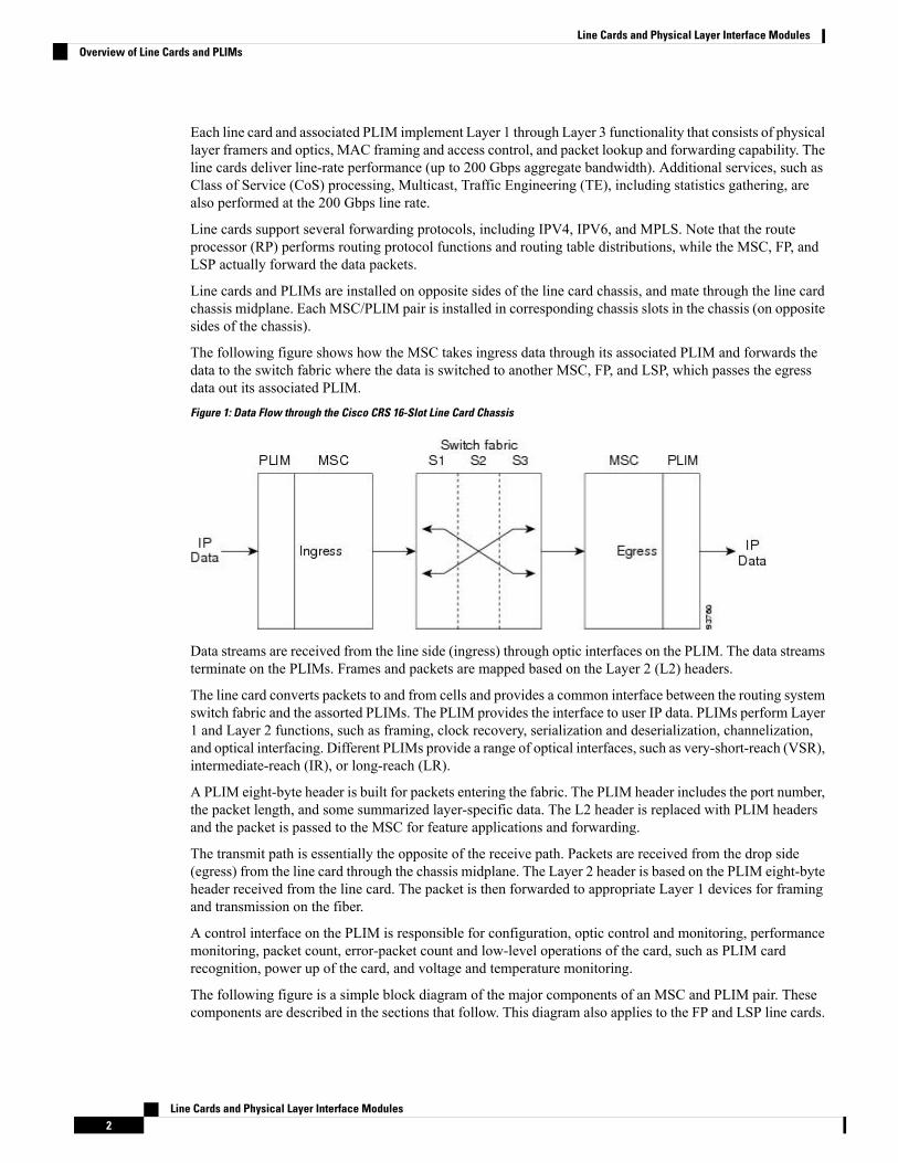
The following figure shows how the MSC takes ingress data through its associated PLIM and forwards thedata to the switch fabric where the data is switched to another MSC, FP, and LSP, which passes the egressdata out its associated PLIM.Figure 1: Data Flow through the Cisco CRS 16-Slot Line Card Chassis
Data streams are received from the line side (ingress) through optic interfaces on the PLIM. The data streamsterminate on the PLIMs. Frames and packets are mapped based on the Layer 2 (L2) headers.
The line card converts packets to and from cells and provides a common interface between the routing systemswitch fabric and the assorted PLIMs. The PLIM provides the interface to user IP data. PLIMs perform Layer1 and Layer 2 functions, such as framing, clock recovery, serialization and deserialization, channelization,and optical interfacing. Different PLIMs provide a range of optical interfaces, such as very-short-reach (VSR),intermediate-reach (IR), or long-reach (LR).
A PLIM eight-byte header is built for packets entering the fabric. The PLIM header includes the port number,the packet length, and some summarized layer-specific data. The L2 header is replaced with PLIM headersand the packet is passed to the MSC for feature applications and forwarding.
The transmit path is essentially the opposite of the receive path. Packets are received from the drop side(egress) from the line card through the chassis midplane. The Layer 2 header is based on the PLIM eight-byteheader received from the line card. The packet is then forwarded to appropriate Layer 1 devices for framingand transmission on the fiber.
A control interface on the PLIM is responsible for configuration, optic control and monitoring, performancemonitoring, packet count, error-packet count and low-level operations of the card, such as PLIM cardrecognition, power up of the card, and voltage and temperature monitoring.
The following figure is a simple block diagram of the major components of an MSC and PLIM pair. Thesecomponents are described in the sections that follow. This diagram also applies to the FP and LSP line cards.
Line Cards and Physical Layer Interface Modules2
Line Cards and Physical Layer Interface ModulesOverview of Line Cards and PLIMs
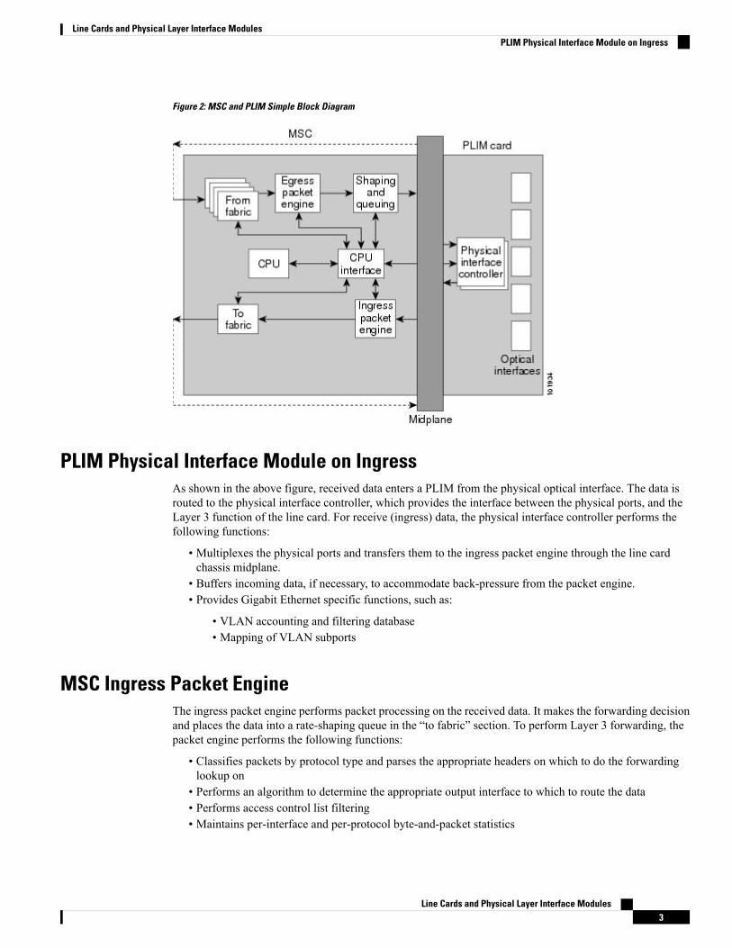
Figure 2: MSC and PLIM Simple Block Diagram
PLIM Physical Interface Module on IngressAs shown in the above figure, received data enters a PLIM from the physical optical interface. The data isrouted to the physical interface controller, which provides the interface between the physical ports, and theLayer 3 function of the line card. For receive (ingress) data, the physical interface controller performs thefollowing functions:
• Multiplexes the physical ports and transfers them to the ingress packet engine through the line cardchassis midplane.
• Buffers incoming data, if necessary, to accommodate back-pressure from the packet engine.• Provides Gigabit Ethernet specific functions, such as:
• VLAN accounting and filtering database• Mapping of VLAN subports
MSC Ingress Packet EngineThe ingress packet engine performs packet processing on the received data. It makes the forwarding decisionand places the data into a rate-shaping queue in the “to fabric” section. To perform Layer 3 forwarding, thepacket engine performs the following functions:
• Classifies packets by protocol type and parses the appropriate headers on which to do the forwardinglookup on
• Performs an algorithm to determine the appropriate output interface to which to route the data• Performs access control list filtering• Maintains per-interface and per-protocol byte-and-packet statistics
Line Cards and Physical Layer Interface Modules3
Line Cards and Physical Layer Interface ModulesPLIM Physical Interface Module on Ingress
• Maintains Netflow accounting• Implements a flexible dual-bucket policing mechanism
MSC To Fabric Section and QueuingThe “to fabric” section of the board takes packets from the ingress packet engine, segments them into fabriccells, and distributes (sprays) the cells into the eight planes of the switch fabric. Because each MSC hasmultiple connections per plane, the “to fabric” section distributes the cells over the links within a fabric plane.The chassis midplane provides the path between the “to fabric” section and the switch fabric (as shown bythe dotted line in Figure 2: MSC and PLIM Simple Block Diagram, on page 3).
• The first level performs ingress shaping and queuing, with a rate-shaping set of queues that are normallyused for input rate-shaping (that is, per input port or per subinterface within an input port), but can alsobe used for other purposes, such as to shape high-priority traffic.
• The second level consists of a set of destination queues where each destination queuemaps to a destinationline card, plus a multicast destination.
Note that the flexible queues are programmable through the Cisco IOS XR software.
MSC From Fabric SectionThe “from fabric” section of the board receives cells from the switch fabric and reassembles the cells into IPpackets. The section then places the IP packets in one of its 8K egress queues, which helps the section adjustfor the speed variations between the switch fabric and the egress packet engine. Egress queues are servicedusing a modified deficit round-robin (MDRR) algorithm. The dotted line in Figure 2: MSC and PLIM SimpleBlock Diagram, on page 3 indicates the path from the midplane to the “from fabric” section.
MSC Egress Packet EngineThe transmit (egress) packet engine performs a lookup on the IP address or MPLS label of the egress packetbased on the information in the ingress MSC buffer header and on additional information in its internal tables.The transmit (egress) packet engine performs transmit side features such as output committed access rate(CAR), access lists, diffServ policing, MAC layer encapsulation, and so on.
Shaping and Queuing FunctionThe transmit packet engine sends the egress packet to the shaping and queuing function (shape and regulatequeues function), which contains the output queues. Here the queues are mapped to ports and classes of service(CoS) within a port. Random early-detection algorithms perform active queue management to maintain lowaverage queue occupancies and delays.
PLIM Physical Interface Section on EgressOn the transmit (egress) path, the physical interface controller provides the interface between the line cardand the physical ports on the PLIM. For the egress path, the controller performs the following functions:
• Support for the physical ports. Each physical interface controller can support up to four physical portsand there can be up to four physical interface controllers on a PLIM.
• Queuing for the ports
Line Cards and Physical Layer Interface Modules4
Line Cards and Physical Layer Interface ModulesMSC To Fabric Section and Queuing
• Back-pressure signalling for the queues• Dynamically shared buffer memory for each queue• A loopback function where transmitted data can be looped back to the receive side
MSC CPU and CPU InterfaceAs shown in Figure 2: MSC and PLIM Simple Block Diagram, on page 3, the MSC contains a centralprocessing unit (CPU) that performs the following tasks:
• MSC configuration• Management• Protocol control
The CPU subsystem includes:
• CPU chip• Layer 3 cache• NVRM• Flash boot PROM• Memory controller• Memory, a dual in-line memory module (DIMM) socket, providing the following:
• Up to 2 GB of 133 MHz DDR SDRAM on the CRS-MSC• Up to 2 GB of 166 MHz DDR SDRAM on the CRS-MSC-B• Up to 8GB of 533 MHz DDR2 SDRAM on the CRS-MSC-140G• Up to 15GB of 533 MHz DDR3 DIMM on the CRS-MSC-X
The CPU interface provides the interface between the CPU subsystem and the other ASICs on the MSC andPLIM.
The MSC also contains a service processor (SP) module that provides:
• MSC and PLIM power-up sequencing• Reset sequencing• JTAG configuration• Power monitoring
The SP, CPU subsystem, and CPU interface module work together to perform housekeeping, communication,and control plane functions for the MSC. The SP controls card power up, environmental monitoring, andEthernet communication with the line card chassis RPs.
The CPU subsystem performs a number of control plane functions, including FIB download receive, localPLU and TLU management, statistics gathering and performance monitoring, and MSC ASIC managementand fault-handling.
The CPU interface module drives high-speed communication ports to all ASICs on the MSC and PLIM. TheCPU talks to the CPU interface module through a high-speed bus attached to its memory controller.
Line Card DescriptionsAn MSC, FP, or LSP fits into any available MSC slot and connects directly to the midplane. There are thefollowing types of MSC, FP, and LSP cards:
Line Cards and Physical Layer Interface Modules5
Line Cards and Physical Layer Interface ModulesMSC CPU and CPU Interface

• MSCs: CRS-MSC (end-of-sale), CRS-MSC-B, CRS-MSC-140G, and CRS-MSC-X/ CRS-MSC-X-L(200G mode)
• FPs: CRS-FP40, CRS-FP140, CRS-FP-X/CRS-FP-X-L (200G mode)• LSPs: CRS-LSP
The power consumption of the line cards are:
• CRS-MSC = 350 W•• CRS-MSC-B = 375 W• CRS-MSC-140G = 446 W• CRS-MSC-X and CRS-MSC-X-L (200G) = 450 W• CRS-FP-40 = 375 W• CRS-FP-X and CRS-FP-X-L (200G) = 450 W• CRS- FP140 = 446 W• CRS- LSP = 446 W
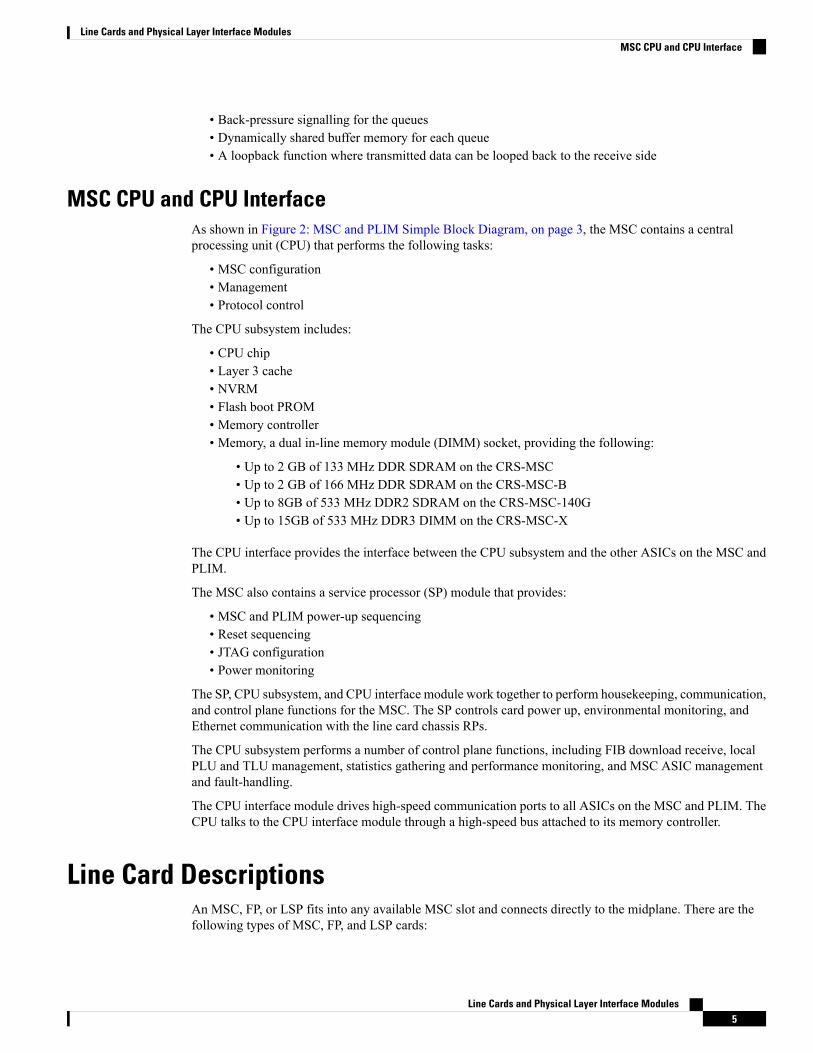
The following figure shows a Cisco CRS routing system CRS-MSC-140G.
Line Cards and Physical Layer Interface Modules6
Line Cards and Physical Layer Interface ModulesLine Card Descriptions
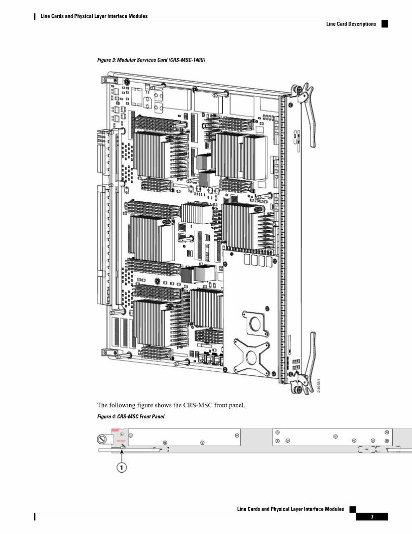
Figure 3: Modular Services Card (CRS-MSC-140G)
The following figure shows the CRS-MSC front panel.Figure 4: CRS-MSC Front Panel
Line Cards and Physical Layer Interface Modules7
Line Cards and Physical Layer Interface ModulesLine Card Descriptions
Alphanumeric LEDs2Status LED1
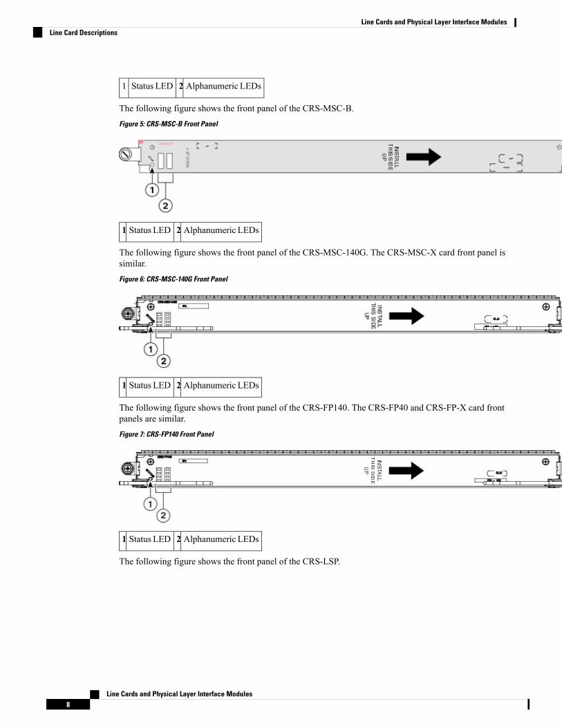
The following figure shows the front panel of the CRS-MSC-B.Figure 5: CRS-MSC-B Front Panel
Alphanumeric LEDs2Status LED1
The following figure shows the front panel of the CRS-MSC-140G. The CRS-MSC-X card front panel issimilar.Figure 6: CRS-MSC-140G Front Panel
Alphanumeric LEDs2Status LED1
The following figure shows the front panel of the CRS-FP140. The CRS-FP40 and CRS-FP-X card frontpanels are similar.Figure 7: CRS-FP140 Front Panel
Alphanumeric LEDs2Status LED1
The following figure shows the front panel of the CRS-LSP.
Line Cards and Physical Layer Interface Modules8
Line Cards and Physical Layer Interface ModulesLine Card Descriptions
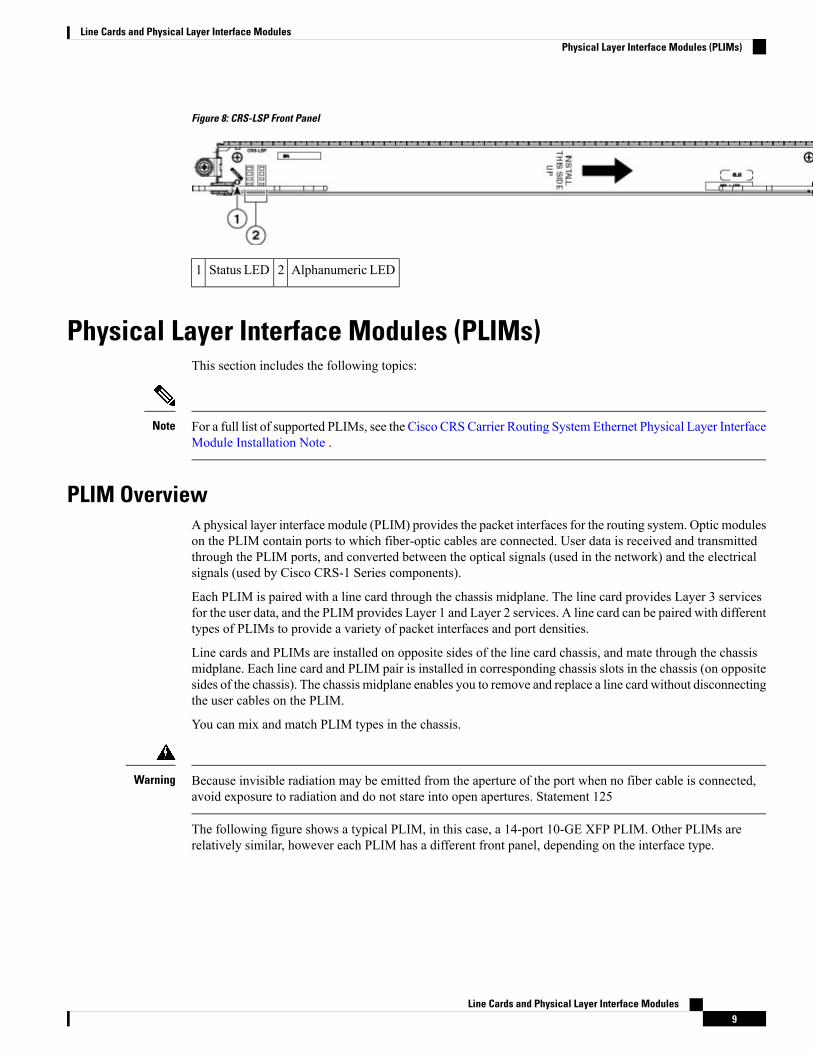
Figure 8: CRS-LSP Front Panel
Alphanumeric LED2Status LED1
Physical Layer Interface Modules (PLIMs)This section includes the following topics:
For a full list of supported PLIMs, see the Cisco CRSCarrier Routing System Ethernet Physical Layer InterfaceModule Installation Note .
Note
PLIM OverviewA physical layer interface module (PLIM) provides the packet interfaces for the routing system. Optic moduleson the PLIM contain ports to which fiber-optic cables are connected. User data is received and transmittedthrough the PLIM ports, and converted between the optical signals (used in the network) and the electricalsignals (used by Cisco CRS-1 Series components).
Each PLIM is paired with a line card through the chassis midplane. The line card provides Layer 3 servicesfor the user data, and the PLIM provides Layer 1 and Layer 2 services. A line card can be paired with differenttypes of PLIMs to provide a variety of packet interfaces and port densities.
Line cards and PLIMs are installed on opposite sides of the line card chassis, and mate through the chassismidplane. Each line card and PLIM pair is installed in corresponding chassis slots in the chassis (on oppositesides of the chassis). The chassis midplane enables you to remove and replace a line card without disconnectingthe user cables on the PLIM.
You can mix and match PLIM types in the chassis.
Because invisible radiation may be emitted from the aperture of the port when no fiber cable is connected,avoid exposure to radiation and do not stare into open apertures. Statement 125
Warning
The following figure shows a typical PLIM, in this case, a 14-port 10-GE XFP PLIM. Other PLIMs arerelatively similar, however each PLIM has a different front panel, depending on the interface type.
Line Cards and Physical Layer Interface Modules9
Line Cards and Physical Layer Interface ModulesPhysical Layer Interface Modules (PLIMs)
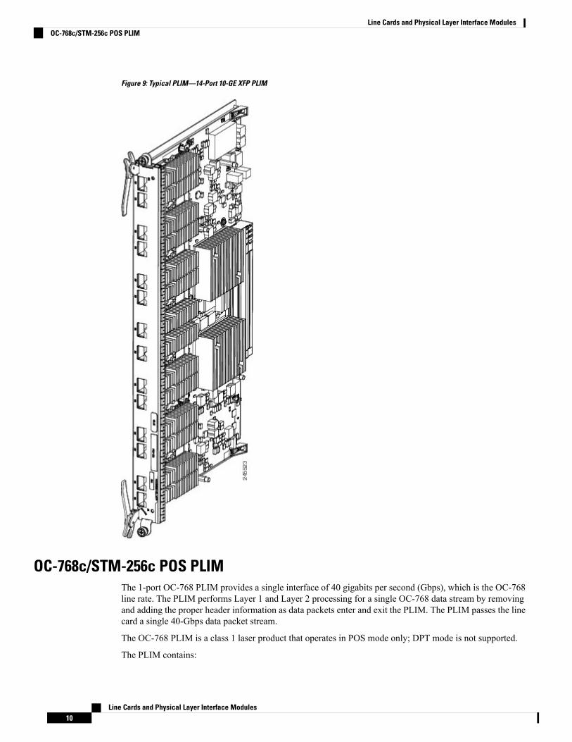
Figure 9: Typical PLIM—14-Port 10-GE XFP PLIM
OC-768c/STM-256c POS PLIMThe 1-port OC-768 PLIM provides a single interface of 40 gigabits per second (Gbps), which is the OC-768line rate. The PLIM performs Layer 1 and Layer 2 processing for a single OC-768 data stream by removingand adding the proper header information as data packets enter and exit the PLIM. The PLIM passes the linecard a single 40-Gbps data packet stream.
The OC-768 PLIM is a class 1 laser product that operates in POS mode only; DPT mode is not supported.
The PLIM contains:
Line Cards and Physical Layer Interface Modules10
Line Cards and Physical Layer Interface ModulesOC-768c/STM-256c POS PLIM
• Optics module—Provides receive (Rx) and transmit (Tx) optic interfaces that comply with ITURecommendation G.693. The module provides short-reach (SR) optics with SC fiber-optic interfaces.
• Framer—Provides processing and termination for SONET/SDH section, line, and path layers, includingalarm processing and automatic protection switching (APS) support.
• Physical interface controller—Provides data packet buffering and Layer 2 processing, including processingfor VLANs and back-pressure signals from the line card.
• Additional components—Include power and clocking components, voltage and temperature sensors, andan identification EEPROM that stores initial configuration and PLIM hardware information.
The Cisco IOS XR software also provides diagnostic functions for the PLIM.
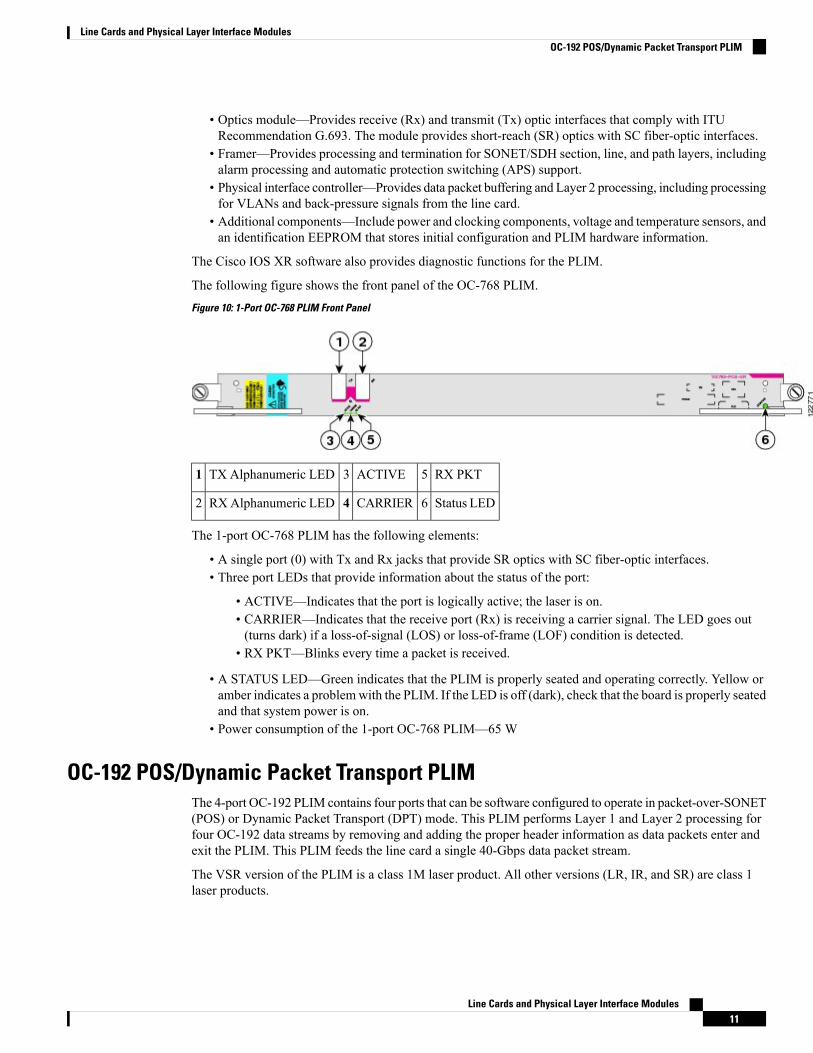
The following figure shows the front panel of the OC-768 PLIM.Figure 10: 1-Port OC-768 PLIM Front Panel
RX PKT5ACTIVE3TX Alphanumeric LED1
Status LED6CARRIER4RXAlphanumeric LED2
The 1-port OC-768 PLIM has the following elements:
• A single port (0) with Tx and Rx jacks that provide SR optics with SC fiber-optic interfaces.• Three port LEDs that provide information about the status of the port:
• ACTIVE—Indicates that the port is logically active; the laser is on.• CARRIER—Indicates that the receive port (Rx) is receiving a carrier signal. The LED goes out(turns dark) if a loss-of-signal (LOS) or loss-of-frame (LOF) condition is detected.
• RX PKT—Blinks every time a packet is received.
• A STATUS LED—Green indicates that the PLIM is properly seated and operating correctly. Yellow oramber indicates a problemwith the PLIM. If the LED is off (dark), check that the board is properly seatedand that system power is on.
• Power consumption of the 1-port OC-768 PLIM—65 W
OC-192 POS/Dynamic Packet Transport PLIMThe 4-port OC-192 PLIM contains four ports that can be software configured to operate in packet-over-SONET(POS) or Dynamic Packet Transport (DPT) mode. This PLIM performs Layer 1 and Layer 2 processing forfour OC-192 data streams by removing and adding the proper header information as data packets enter andexit the PLIM. This PLIM feeds the line card a single 40-Gbps data packet stream.
The VSR version of the PLIM is a class 1M laser product. All other versions (LR, IR, and SR) are class 1laser products.
Line Cards and Physical Layer Interface Modules11
Line Cards and Physical Layer Interface ModulesOC-192 POS/Dynamic Packet Transport PLIM
Dynamic Packet Transport (DPT) mode is not available at this time.Note
The 4-port OC-192 consists of:
• Opticsmodules—Provide receive (Rx) and transmit (Tx) optic interfaces that complywith GR-253-CORE.The PLIM supports the following types of optics:
• Long-reach (LR) optics with SC fiber-optic interfaces• Intermediate-reach (IR) optics with SC fiber-optic interfaces• Short-reach (SR) optics with SC fiber-optic interfaces• Very-short-reach (VSR) optics with standard MTP (MPO) multi-fiber optic interfaces
• Framers—Provide processing and termination for SONET Section, Line, and Path layers. This includesalarm processing and automatic protection switching (APS) support. The framer supports both packetand cell processing for a multiservice operating mode.
• DPT or transparent mode components—Provide the MAC layer function for the Spatial Reuse Protocolused in the DPT mode. When the PLIM is in POS mode, these components operate in the transparentmode.
• Physical interface controller—Provides data packet buffering and Layer 2 processing and multiplexingand demultiplexing the four OC-192 data streams. This includes processing for VLANs and back-pressuresignals from the line card.
• Additional components—Provide power, clocking, voltage and temperature sensing, and an identificationEEPROM that stores initial configuration information and details about the PLIM type and hardwarerevision.
• Power consumption of the 4-port OC-192 PLIM—138 W
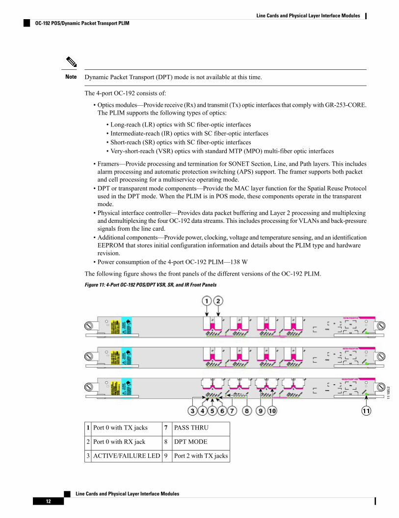
The following figure shows the front panels of the different versions of the OC-192 PLIM.Figure 11: 4-Port OC-192 POS/DPT VSR, SR, and IR Front Panels
PASS THRU7Port 0 with TX jacks1
DPT MODE8Port 0 with RX jack2
Port 2 with TX jacks9ACTIVE/FAILURE LED3
Line Cards and Physical Layer Interface Modules12
Line Cards and Physical Layer Interface ModulesOC-192 POS/Dynamic Packet Transport PLIM
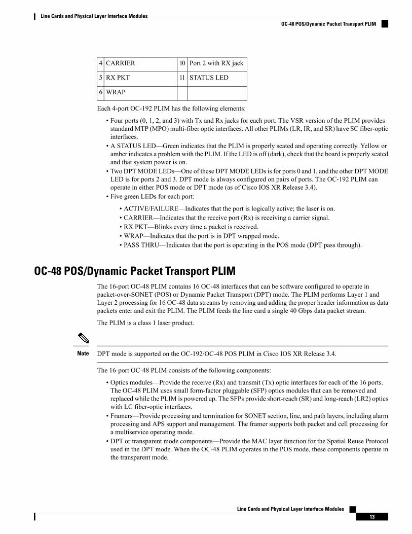
Port 2 with RX jack10CARRIER4
STATUS LED11RX PKT5
WRAP6
Each 4-port OC-192 PLIM has the following elements:
• Four ports (0, 1, 2, and 3) with Tx and Rx jacks for each port. The VSR version of the PLIM providesstandardMTP (MPO) multi-fiber optic interfaces. All other PLIMs (LR, IR, and SR) have SC fiber-opticinterfaces.
• A STATUS LED—Green indicates that the PLIM is properly seated and operating correctly. Yellow oramber indicates a problemwith the PLIM. If the LED is off (dark), check that the board is properly seatedand that system power is on.
• TwoDPTMODELEDs—One of these DPTMODELEDs is for ports 0 and 1, and the other DPTMODELED is for ports 2 and 3. DPT mode is always configured on pairs of ports. The OC-192 PLIM canoperate in either POS mode or DPT mode (as of Cisco IOS XR Release 3.4).
• Five green LEDs for each port:
• ACTIVE/FAILURE—Indicates that the port is logically active; the laser is on.• CARRIER—Indicates that the receive port (Rx) is receiving a carrier signal.• RX PKT—Blinks every time a packet is received.• WRAP—Indicates that the port is in DPT wrapped mode.• PASS THRU—Indicates that the port is operating in the POS mode (DPT pass through).
OC-48 POS/Dynamic Packet Transport PLIMThe 16-port OC-48 PLIM contains 16 OC-48 interfaces that can be software configured to operate inpacket-over-SONET (POS) or Dynamic Packet Transport (DPT) mode. The PLIM performs Layer 1 andLayer 2 processing for 16 OC-48 data streams by removing and adding the proper header information as datapackets enter and exit the PLIM. The PLIM feeds the line card a single 40 Gbps data packet stream.
The PLIM is a class 1 laser product.
DPT mode is supported on the OC-192/OC-48 POS PLIM in Cisco IOS XR Release 3.4.Note
The 16-port OC-48 PLIM consists of the following components:
• Optics modules—Provide the receive (Rx) and transmit (Tx) optic interfaces for each of the 16 ports.The OC-48 PLIM uses small form-factor pluggable (SFP) optics modules that can be removed andreplaced while the PLIM is powered up. The SFPs provide short-reach (SR) and long-reach (LR2) opticswith LC fiber-optic interfaces.
• Framers—Provide processing and termination for SONET section, line, and path layers, including alarmprocessing and APS support and management. The framer supports both packet and cell processing fora multiservice operating mode.
• DPT or transparent mode components—Provide the MAC layer function for the Spatial Reuse Protocolused in the DPT mode. When the OC-48 PLIM operates in the POS mode, these components operate inthe transparent mode.
Line Cards and Physical Layer Interface Modules13
Line Cards and Physical Layer Interface ModulesOC-48 POS/Dynamic Packet Transport PLIM
• Physical interface controller—Provides data packet buffering and Layer 2 processing and multiplexingand demultiplexing of the 16 OC-48 data streams. This includes processing for VLANs and back-pressuresignals from the line card.
• Additional components—Provide power, clocking, voltage and temperature sensing, and an identificationEEPROM that stores initial configuration information and details about the PLIM type and hardwarerevision.
• Power consumption of the OC-48 PLIM—136 W
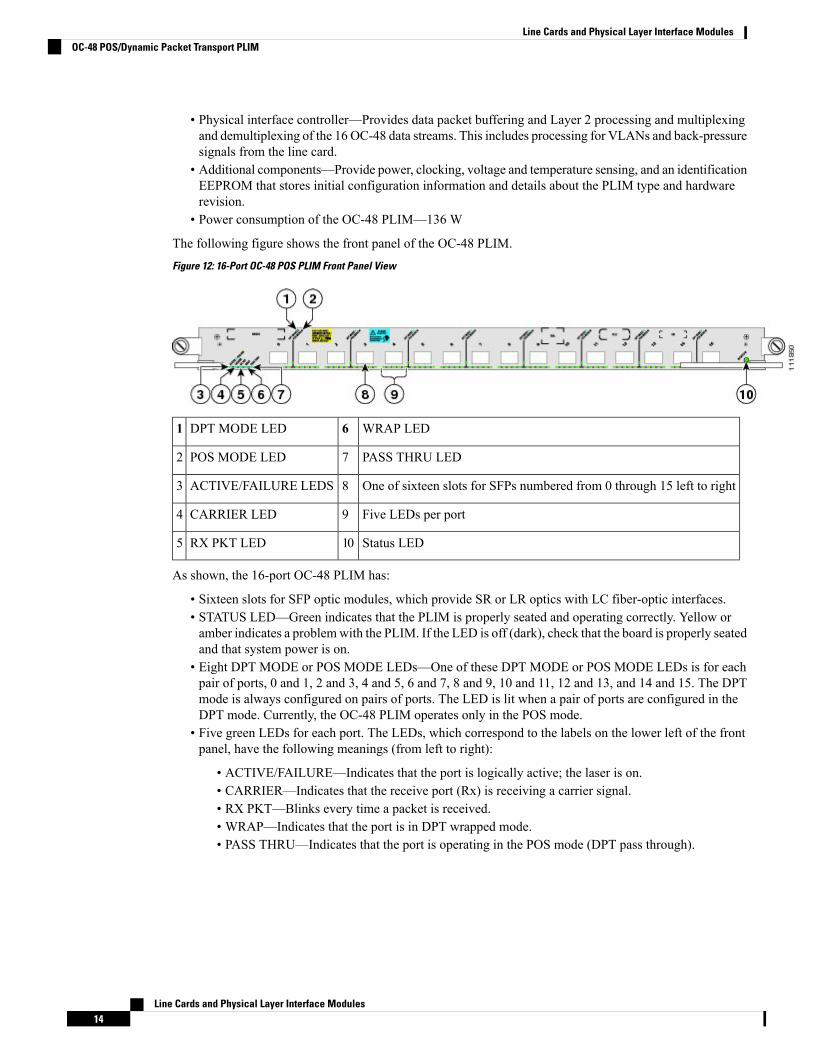
The following figure shows the front panel of the OC-48 PLIM.Figure 12: 16-Port OC-48 POS PLIM Front Panel View
WRAP LED6DPT MODE LED1
PASS THRU LED7POS MODE LED2
One of sixteen slots for SFPs numbered from 0 through 15 left to right8ACTIVE/FAILURE LEDS3
Five LEDs per port9CARRIER LED4
Status LED10RX PKT LED5
As shown, the 16-port OC-48 PLIM has:
• Sixteen slots for SFP optic modules, which provide SR or LR optics with LC fiber-optic interfaces.• STATUS LED—Green indicates that the PLIM is properly seated and operating correctly. Yellow oramber indicates a problemwith the PLIM. If the LED is off (dark), check that the board is properly seatedand that system power is on.
• Eight DPT MODE or POS MODE LEDs—One of these DPT MODE or POS MODE LEDs is for eachpair of ports, 0 and 1, 2 and 3, 4 and 5, 6 and 7, 8 and 9, 10 and 11, 12 and 13, and 14 and 15. The DPTmode is always configured on pairs of ports. The LED is lit when a pair of ports are configured in theDPT mode. Currently, the OC-48 PLIM operates only in the POS mode.
• Five green LEDs for each port. The LEDs, which correspond to the labels on the lower left of the frontpanel, have the following meanings (from left to right):
• ACTIVE/FAILURE—Indicates that the port is logically active; the laser is on.• CARRIER—Indicates that the receive port (Rx) is receiving a carrier signal.• RX PKT—Blinks every time a packet is received.• WRAP—Indicates that the port is in DPT wrapped mode.• PASS THRU—Indicates that the port is operating in the POS mode (DPT pass through).
Line Cards and Physical Layer Interface Modules14
Line Cards and Physical Layer Interface ModulesOC-48 POS/Dynamic Packet Transport PLIM
10-Gigabit Ethernet XENPAK PLIMThe 8-port 10-Gigabit Ethernet (GE) XENPAKPLIM provides from one to eight 10-GE interfaces. The PLIMsupports from one to eight pluggable XENPAK optic modules that provide the 10-GE interfaces for the card.The PLIM performs Layer 1 and Layer 2 processing for up to eight 10-GE data streams by removing andadding the proper header information as data packets enter and exit the PLIM.
Although the PLIM can terminate up to 80 Gbps of traffic, the line card forwards traffic at 40 Gbps. Therefore,the PLIM provides 40 Gbps of throughput, which it passes to the line card as two 20-Gbps data packet streams:
• Ports 0 to 3 (the upper set of ports) provide 20 Gbps of throughput.• Ports 4 to 7 (the lower set of ports) provide another 20 Gbps of throughput.
Oversubscription of 10-GE Ports
If more than 2 optic modules are installed in either set of ports, oversubscription occurs on all ports in thatset. For example, if modules are installed in ports 0 and 1, each interface has 10 Gbps of throughput. Addinganother module in port 2 causes oversubscription on all of the interfaces (0, 1, and 2).
If your configuration cannot support oversubscription, use the following guidelines to determine which PLIMslots to install optic modules in.
Note
• Do not install more than four optic modules in each PLIM.• Install the optic modules in any one of the following sets of PLIM slots:
• Slots 0 and 1, and 4 and 5• Slots 0 and 1, and 6 and 7• Slots 2 and 3, and 4 and 5• Slots 2 and 3, and 6 and 7
If your configuration can support oversubscription and you want to install more than four optic modules in aPLIM, we recommend that you install additional modules in empty slots, alternating between upper and lowerports. For example, if you install a fifth optic module in an empty slot in the upper set of ports (0 to 3), besure to install the next module in an empty slot in the lower set of ports (4 to 7), and so on.
10-GE PLIM Components
The 8-port 10-GE XENPAK PLIM consists of:
• Optic modules—Provide receive (Rx) and transmit (Tx) optical interfaces that comply with IEEE 802.3ae.The PLIM supports from one to eight pluggable XENPAK optic modules, each providing full-duplexlong-reach (LR) optics with SC fiber-optic interfaces. Note that the PLIM automatically shuts down anyoptic module that is not a valid type.
• Physical interface controller—Provides data packet buffering, Layer 2 processing, and multiplexing anddemultiplexing of the 10-GE data streams, including processing for VLANs and back-pressure signalsfrom the line card.
• Additional components—Include power and clocking components, voltage and temperature sensors, andan identification EEPROM that stores initial configuration and PLIM hardware information.
The following figure shows the front panel of the 10-GE XENPAK PLIM.
Line Cards and Physical Layer Interface Modules15
Line Cards and Physical Layer Interface Modules10-Gigabit Ethernet XENPAK PLIM
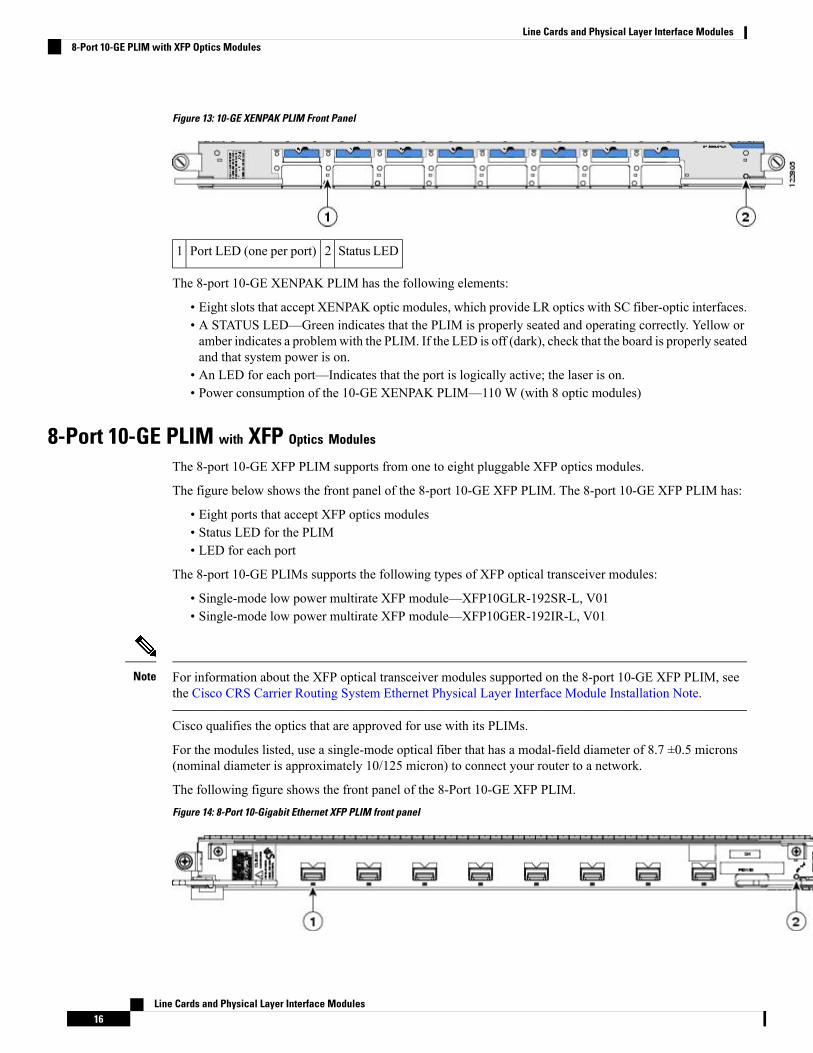
Figure 13: 10-GE XENPAK PLIM Front Panel
Status LED2Port LED (one per port)1
The 8-port 10-GE XENPAK PLIM has the following elements:
• Eight slots that accept XENPAK optic modules, which provide LR optics with SC fiber-optic interfaces.• A STATUS LED—Green indicates that the PLIM is properly seated and operating correctly. Yellow oramber indicates a problemwith the PLIM. If the LED is off (dark), check that the board is properly seatedand that system power is on.
• An LED for each port—Indicates that the port is logically active; the laser is on.• Power consumption of the 10-GE XENPAK PLIM—110 W (with 8 optic modules)
8-Port 10-GE PLIM with XFP Optics Modules
The 8-port 10-GE XFP PLIM supports from one to eight pluggable XFP optics modules.
The figure below shows the front panel of the 8-port 10-GE XFP PLIM. The 8-port 10-GE XFP PLIM has:
• Eight ports that accept XFP optics modules• Status LED for the PLIM• LED for each port
The 8-port 10-GE PLIMs supports the following types of XFP optical transceiver modules:
• Single-mode low power multirate XFP module—XFP10GLR-192SR-L, V01• Single-mode low power multirate XFP module—XFP10GER-192IR-L, V01
For information about the XFP optical transceiver modules supported on the 8-port 10-GE XFP PLIM, seethe Cisco CRS Carrier Routing System Ethernet Physical Layer Interface Module Installation Note.
Note
Cisco qualifies the optics that are approved for use with its PLIMs.
For the modules listed, use a single-mode optical fiber that has a modal-field diameter of 8.7 ±0.5 microns(nominal diameter is approximately 10/125 micron) to connect your router to a network.
The following figure shows the front panel of the 8-Port 10-GE XFP PLIM.Figure 14: 8-Port 10-Gigabit Ethernet XFP PLIM front panel
Line Cards and Physical Layer Interface Modules16
Line Cards and Physical Layer Interface Modules8-Port 10-GE PLIM with XFP Optics Modules
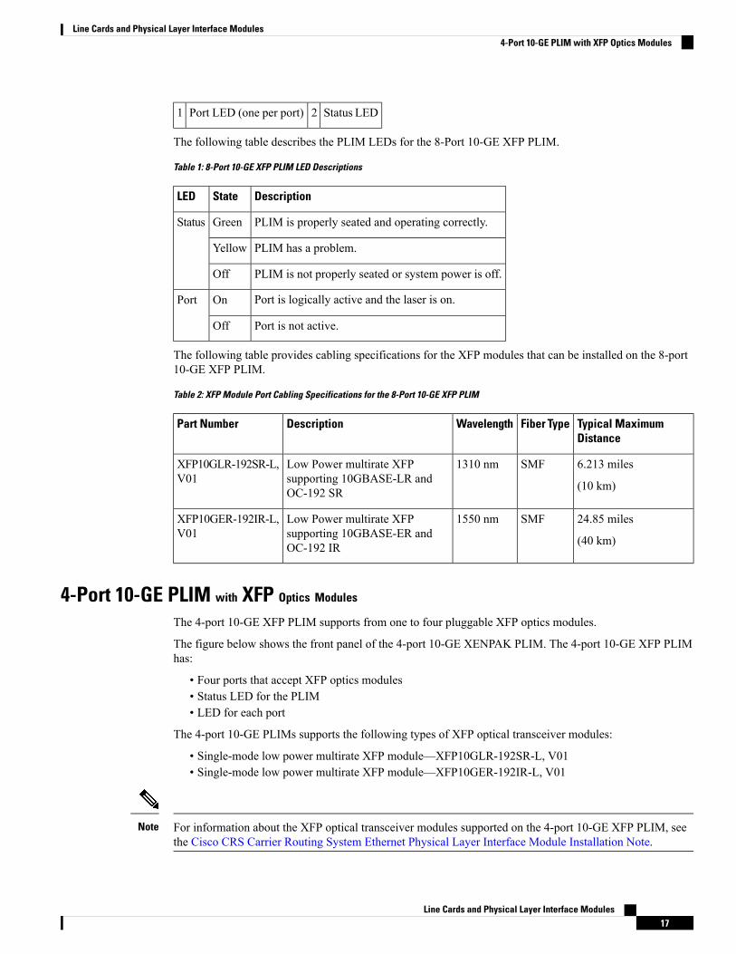
Status LED2Port LED (one per port)1
The following table describes the PLIM LEDs for the 8-Port 10-GE XFP PLIM.
Table 1: 8-Port 10-GE XFP PLIM LED Descriptions
DescriptionStateLED
PLIM is properly seated and operating correctly.GreenStatus
PLIM has a problem.Yellow
PLIM is not properly seated or system power is off.Off
Port is logically active and the laser is on.OnPort
Port is not active.Off
The following table provides cabling specifications for the XFP modules that can be installed on the 8-port10-GE XFP PLIM.
Table 2: XFP Module Port Cabling Specifications for the 8-Port 10-GE XFP PLIM
Typical MaximumDistance
Fiber TypeWavelengthDescriptionPart Number
6.213 miles
(10 km)
SMF1310 nmLow Power multirate XFPsupporting 10GBASE-LR andOC-192 SR
XFP10GLR-192SR-L,V01
24.85 miles
(40 km)
SMF1550 nmLow Power multirate XFPsupporting 10GBASE-ER andOC-192 IR
XFP10GER-192IR-L,V01
4-Port 10-GE PLIM with XFP Optics Modules
The 4-port 10-GE XFP PLIM supports from one to four pluggable XFP optics modules.
The figure below shows the front panel of the 4-port 10-GE XENPAK PLIM. The 4-port 10-GE XFP PLIMhas:
• Four ports that accept XFP optics modules• Status LED for the PLIM• LED for each port
The 4-port 10-GE PLIMs supports the following types of XFP optical transceiver modules:
• Single-mode low power multirate XFP module—XFP10GLR-192SR-L, V01• Single-mode low power multirate XFP module—XFP10GER-192IR-L, V01
For information about the XFP optical transceiver modules supported on the 4-port 10-GE XFP PLIM, seethe Cisco CRS Carrier Routing System Ethernet Physical Layer Interface Module Installation Note.
Note
Line Cards and Physical Layer Interface Modules17
Line Cards and Physical Layer Interface Modules4-Port 10-GE PLIM with XFP Optics Modules
Cisco qualifies the optics that are approved for use with its PLIMs.
For the modules listed, use a single-mode optical fiber that has a modal-field diameter of 8.7 ±0.5 microns(nominal diameter is approximately 10/125 micron) to connect your router to a network.
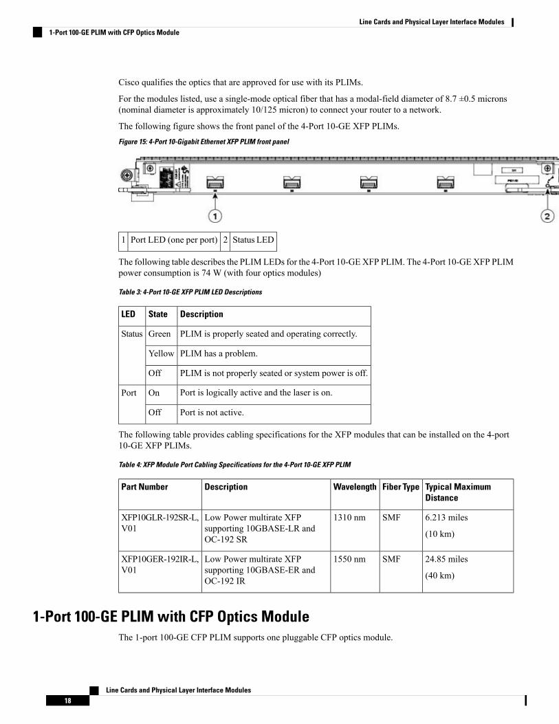
The following figure shows the front panel of the 4-Port 10-GE XFP PLIMs.Figure 15: 4-Port 10-Gigabit Ethernet XFP PLIM front panel
Status LED2Port LED (one per port)1
The following table describes the PLIMLEDs for the 4-Port 10-GEXFP PLIM. The 4-Port 10-GEXFP PLIMpower consumption is 74 W (with four optics modules)
Table 3: 4-Port 10-GE XFP PLIM LED Descriptions
DescriptionStateLED
PLIM is properly seated and operating correctly.GreenStatus
PLIM has a problem.Yellow
PLIM is not properly seated or system power is off.Off
Port is logically active and the laser is on.OnPort
Port is not active.Off
The following table provides cabling specifications for the XFP modules that can be installed on the 4-port10-GE XFP PLIMs.
Table 4: XFP Module Port Cabling Specifications for the 4-Port 10-GE XFP PLIM
Typical MaximumDistance
Fiber TypeWavelengthDescriptionPart Number
6.213 miles
(10 km)
SMF1310 nmLow Power multirate XFPsupporting 10GBASE-LR andOC-192 SR
XFP10GLR-192SR-L,V01
24.85 miles
(40 km)
SMF1550 nmLow Power multirate XFPsupporting 10GBASE-ER andOC-192 IR
XFP10GER-192IR-L,V01
1-Port 100-GE PLIM with CFP Optics ModuleThe 1-port 100-GE CFP PLIM supports one pluggable CFP optics module.
Line Cards and Physical Layer Interface Modules18
Line Cards and Physical Layer Interface Modules1-Port 100-GE PLIM with CFP Optics Module
The 1-port 100-GE PLIM has:
• One port that accepts a CFP optics module• Status LED for the PLIM• Four LED indicators for the single port
The 1-port 100-GE PLIM supports the following types of CFP optical transceiver modules:
• CFP-100GE-LR4, V01
Cisco qualifies the optics that are approved for use with its PLIMs.
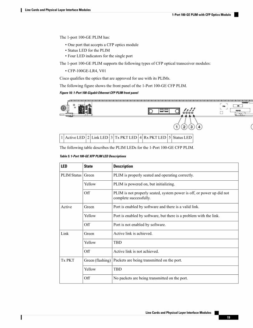
The following figure shows the front panel of the 1-Port 100-GE CFP PLIM.Figure 16: 1-Port 100-Gigabit Ethernet CFP PLIM front panel
Status LED5Rx PKT LED4Tx PKT LED3Link LED2Active LED1
The following table describes the PLIM LEDs for the 1-Port 100-GE CFP PLIM.
Table 5: 1-Port 100-GE XFP PLIM LED Descriptions
DescriptionStateLED
PLIM is properly seated and operating correctly.GreenPLIMStatus
PLIM is powered on, but initializing.Yellow
PLIM is not properly seated, system power is off, or power up did notcomplete successfully.
Off
Port is enabled by software and there is a valid link.GreenActive
Port is enabled by software, but there is a problem with the link.Yellow
Port is not enabled by software.Off
Active link is achieved.GreenLink
TBDYellow
Active link is not achieved.Off
Packets are being transmitted on the port.Green (flashing)Tx PKT
TBDYellow
No packets are being transmitted on the port.Off
Line Cards and Physical Layer Interface Modules19
Line Cards and Physical Layer Interface Modules1-Port 100-GE PLIM with CFP Optics Module
DescriptionStateLED
Packets are being received on the port.Green (flashing)Rx PKT
TBDYellow
No packets are being received on the port.Off
20-Port 10-GE PLIM with XFP Optics Modules
The 20-port 10-GE XFP PLIM supports from one to twenty pluggable XFP optics modules.
The 20-port 10-GE PLIM has:
• Twenty ports that accept XFP optics modules• Status LED for the PLIM• Port status LED for each port
The 20-port 10-GE PLIM supports the following types of XFP optical transceiver modules:
• Single-mode low power multirate XFP module—XFP10GLR-192SR-L, V01• Single-mode low power multirate XFP module—XFP10GER-192IR-L, V01
For information about the XFP optical transceiver modules supported on the 20-port 10-GE XFP PLIM, seethe Cisco CRS Carrier Routing System Ethernet Physical Layer Interface Module Installation Note.
Note
The 20-port XFP PLIM has a fixed power budget for the pluggable XFP optics. See XFP Optics PowerManagement, on page 23 for detailed information.
Note
Cisco qualifies the optics that are approved for use with its PLIMs.
For the modules listed, use a single-mode optical fiber that has a modal-field diameter of 8.7 ±0.5 microns(nominal diameter is approximately 10/125 micron) to connect your router to a network.
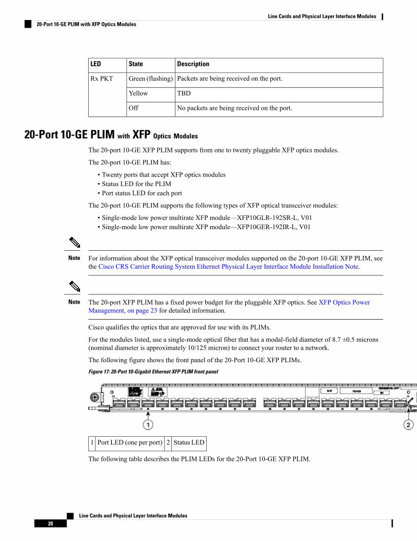
The following figure shows the front panel of the 20-Port 10-GE XFP PLIMs.Figure 17: 20-Port 10-Gigabit Ethernet XFP PLIM front panel
Status LED2Port LED (one per port)1
The following table describes the PLIM LEDs for the 20-Port 10-GE XFP PLIM.
Line Cards and Physical Layer Interface Modules20
Line Cards and Physical Layer Interface Modules20-Port 10-GE PLIM with XFP Optics Modules
Table 6: 20-Port 10-GE XFP PLIM LED Descriptions
DescriptionStateLED
PLIM is properly seated and operating correctly.GreenPLIMStatus
PLIM is powered on, but initializing.Yellow
PLIM is not properly seated, system power is off, or power up did not completesuccessfully.
Off
Port is enabled by software and there is a valid link.OnPort Status
Port is enabled by software, but there is a problem with the link.Yellow
Port is not enabled by software.Off
The 20-port 10-GE XFP PLIM has the following physical characteristics:
• Height—20.6 in (52.2 cm)• Depth—11.2 in (28.4 cm)• Width—1.8 in (4.5 cm)• Weight—8.45 lb (3.8 kg)• Power consumption—150 W (120 W with no optics installed, 30 W optics budget)
The 20-port 10-GE XFP PLIM can have all 20 ports filled with SR (1.5W) 10km XFPs. If you use opticsother than SR, you must be careful not to exceed the power budget, which may result in some ports remainingunpowered. Cisco IOS XR software enables the ports in a sequence that allows the configuration to remainwithin the optics power budget. For more details on how the software controls PLIM power consumption(150 W, 120 W with no optics installed, 30 W optics budget), see Cisco IOS XR Interface and HardwareComponent Command Reference for the Cisco CRS Router .
Caution
14-Port 10-GE PLIM with XFP Optics Modules
The 14-port 10-GE XFP PLIM supports from one to fourteen pluggable XFP optics modules.
The 14-port 10-GE PLIM has:
• Fourteen ports that accept XFP optics modules• Status LED for the PLIM• LED for each port
The14-port 10-GE PLIM supports the following types of XFP optical transceiver modules:
• Single-mode low power multirate XFP module—XFP10GLR-192SR-L, V01• Single-mode low power multirate XFP module—XFP10GER-192IR-L, V01
Cisco qualifies the optics that are approved for use with its PLIMs.
For the modules listed, use a single-mode optical fiber that has a modal-field diameter of 8.7 ±0.5 microns(nominal diameter is approximately 10/125 micron) to connect your router to a network.
The following figure shows the front panel of the 14-Port 10-GE XFP PLIMs.
Line Cards and Physical Layer Interface Modules21
Line Cards and Physical Layer Interface Modules14-Port 10-GE PLIM with XFP Optics Modules
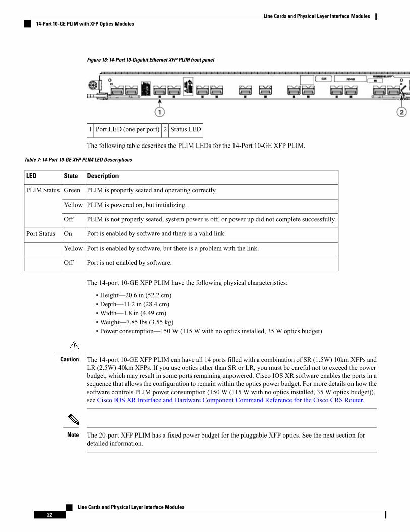
Figure 18: 14-Port 10-Gigabit Ethernet XFP PLIM front panel
Status LED2Port LED (one per port)1
The following table describes the PLIM LEDs for the 14-Port 10-GE XFP PLIM.
Table 7: 14-Port 10-GE XFP PLIM LED Descriptions
DescriptionStateLED
PLIM is properly seated and operating correctly.GreenPLIMStatus
PLIM is powered on, but initializing.Yellow
PLIM is not properly seated, system power is off, or power up did not complete successfully.Off
Port is enabled by software and there is a valid link.OnPort Status
Port is enabled by software, but there is a problem with the link.Yellow
Port is not enabled by software.Off
The 14-port 10-GE XFP PLIM have the following physical characteristics:
• Height—20.6 in (52.2 cm)• Depth—11.2 in (28.4 cm)• Width—1.8 in (4.49 cm)• Weight—7.85 lbs (3.55 kg)• Power consumption—150 W (115 W with no optics installed, 35 W optics budget)
The 14-port 10-GE XFP PLIM can have all 14 ports filled with a combination of SR (1.5W) 10km XFPs andLR (2.5W) 40km XFPs. If you use optics other than SR or LR, you must be careful not to exceed the powerbudget, which may result in some ports remaining unpowered. Cisco IOS XR software enables the ports in asequence that allows the configuration to remain within the optics power budget. For more details on how thesoftware controls PLIM power consumption (150 W (115 W with no optics installed, 35 W optics budget)),see Cisco IOS XR Interface and Hardware Component Command Reference for the Cisco CRS Router.
Caution
The 20-port XFP PLIM has a fixed power budget for the pluggable XFP optics. See the next section fordetailed information.
Note
Line Cards and Physical Layer Interface Modules22
Line Cards and Physical Layer Interface Modules14-Port 10-GE PLIM with XFP Optics Modules
XFP Optics Power ManagementThe 20- and 14-port XFP PLIMs have a fixed power budget for the pluggable XFP optics. The XFP pluggableoptics for the 20- and 14-port XFP PLIMs have different power consumptions based on their reach and type.The number of XFPs which will power up in a PLIM depends on their aggregate power consumption withinthe allocated power budget.
During XFP insertion, the power is allotted to the optics based on the insertion order of the XFPs. On bootup and reload, priority is re-assigned to the lower numbered ports.
The recommended insertion sequence is to alternate between inserting XFPs in lowest numbered ports foreach interface device driver ASIC to avoid oversubscription. The insertion order for a 20 Port PLIM wouldbe “0,10,1,11,2,12,...9,19.” For a 14 Port PLIM, insertion order would be “0,7,1,8,...6,13.”
If the PLIM power budget is exceeded, a console log message is displayed informing the user the powerbudget has been exceeded and to remove the XFP:
plim_[x]ge: %L2-PLIM-6-NO_POWER_XFP : Port <port number>, Not enough power availableto power XFP, powering off
Any unpowered XFPs should be removed to ensure that the same XFPs that were powered before a reloadare the same XFPs that are powered after a reload. Removing the unpowered XFPs prevents the powereddown XFPs being given priority after the reload.
A show command is provided to indicate howmuch of the XFP power budget is currently used and howmuchpower an XFP is consuming:
show controllers tenGigE 0/3/0/0 internal
PLIM Impedance CarrierA PLIM impedance carrier must be installed in each empty PLIM slot in the Cisco CRS-1 Series chassis (seethe following figure). The CRS 16-slot chassis is shipped with impedance carriers installed in the empty slots.The impedance carrier preserves the integrity of the chassis and is required for EMI compliance and propercooling in the chassis.
Line Cards and Physical Layer Interface Modules23
Line Cards and Physical Layer Interface ModulesXFP Optics Power Management
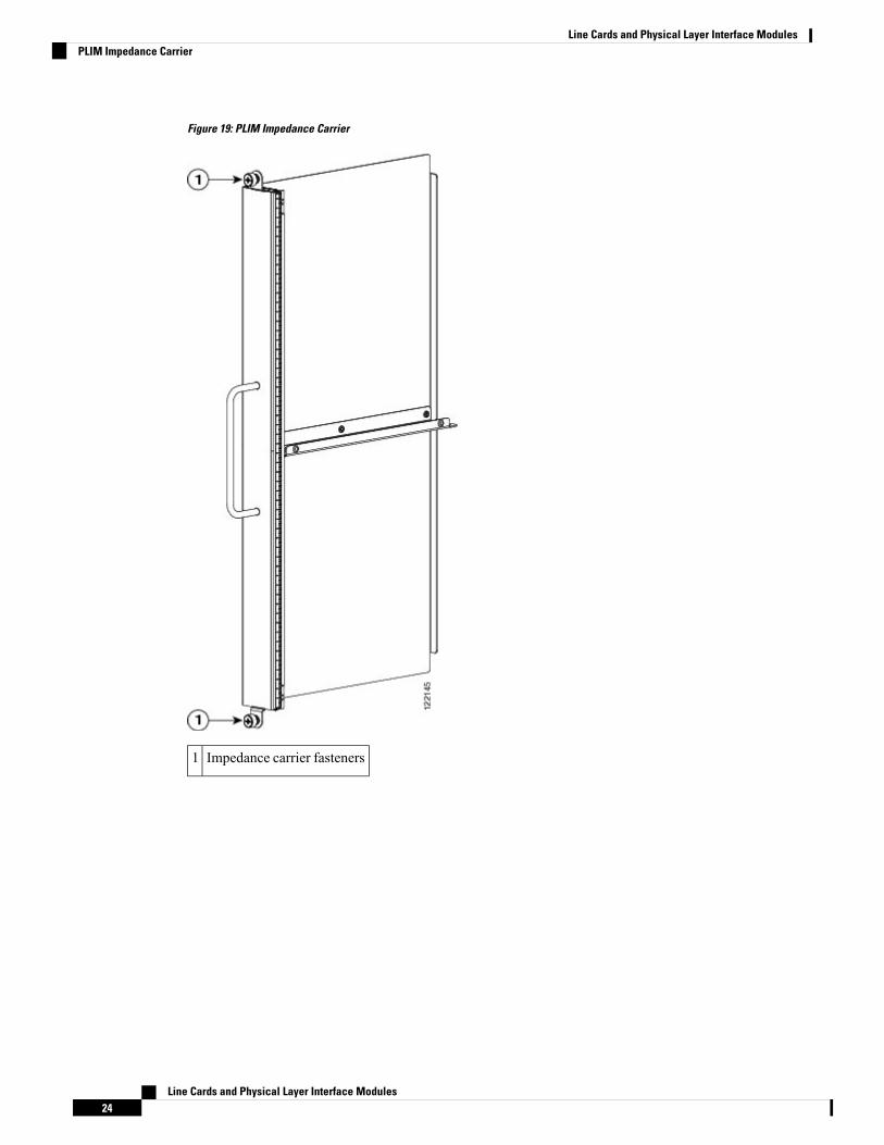
Figure 19: PLIM Impedance Carrier
Impedance carrier fasteners1
Line Cards and Physical Layer Interface Modules24
Line Cards and Physical Layer Interface ModulesPLIM Impedance Carrier