LightTour: Enabling Museum Audio Tour with Visible Light
12
LightTour: Enabling Museum Audio Tour with Visible Light Lennert Vanmunster KU Leuven, Belgium [email protected] Jona Beysens KU Leuven, Belgium [email protected] Qing Wang TU Delft, the Netherlands [email protected] Sofie Pollin KU Leuven, Belgium sofi[email protected] Abstract We exploit visible light in museums to design LightTour, a wirelessly networked system empowered by visible light that provides audio tour service to visitors. LightTour sup- ports full-duplex transmissions with a single multi-band op- tical receiving antenna at each transceiver: for the downlink, the access points (APs) broadcast audio streams to visitors’ devices through visible light communication; for the uplink, the devices send visitor’s feedback to APs through infrared light transmission. To network a number of APs and de- vices, we identify two main challenges: (1) self-interference at the APs, caused by the floor reflection of their downlink signals, that degrades uplink transmissions; (2) the uplink hidden-device problem. In this work, we develop an online low-complexity method that can achieve maximally 30 dB self-interference cancellation at APs. We design a new MAC protocol – full-duplex carrier sense multiple access with col- lision detection & hidden avoidance (FD-CSMA/CD-HA) – to solve the hidden-device problem and to provide reli- able and high-throughput audio broadcasting. To evaluate the system performance of LightTour, we build a prototype with off-the-shelf components. Besides, we develop a sim- ulator to assess large-scale scenarios. The results validate our self-interference cancellation method’s feasibility and demonstrate FD-CSMA/CD-HA’s robustness and its advan- tage over existing protocols. 1 Introduction Audio tours have become ubiquitous in museums. An au- dio tour provides a visitor with location-based spoken com- mentary about museums’ exhibition through a hand-held de- vice. In this way, visitors can experience museums in a more personalized and effortless manner. Modern audio tour sys- tems can be broadly divided into four categories based on their operating principles: 1. Local audio storage with manual track selection: audio is stored locally on each device. These systems require user input, usually via buttons or a touchscreen, for au- dio track selection and playback. 2. Local audio storage with location-aware track selec- tion: these systems sense the user’s location using radio-frequency (RF) based positioning methods. The audio track stored on the hand-held device is played back based on the current user position. 3. Wireless audio transmission with manual track selec- tion: in these systems the user manually selects the au- dio track on the device. Subsequently, the device sends a request for the track to a nearby AP, which then trans- mits that audio track to the device using RF communi- cation. 4. Wireless audio transmission with location-aware track selection: these systems are the most advanced and in- clude both a mechanism for user localization and wire- less audio transmission through RF communication. Motivated by the pervasive existence of visible light in museums and the recent advances in visible light commu- nication (VLC), we design an indoor location-based audio tour system empowered by light. In our system LightTour, automated location-based audio transmission is realized by modulating the LEDs whose primary function is to provide illumination (Category 4 system above). Additionally, Light- Tour supports full-duplex transmissions in which an uplink channel is provided for users to send real-time feedback mes- sages to the museum. The uplink channel for real-time, location-based feedback messages can improve future user experience and museum management. Another example of an uplink application that improves museum management is real-time tracking and collection of visitor locations at a cen- tral entity. The advantages of light communication enabled audio tour systems over existing RF-based systems are threefold. The first advantage is the reduced installation cost and hard- ware complexity. Not only do RF systems require ad- ditional installation of APs, they also increase the trans- mitter/receiver (TX/RX) hardware complexity significantly. LightTour, on the other hand, offers easy installation and low hardware complexity by integrating simple TX/RX hard- ware into the lighting infrastructure and exploiting a single International Conference on Embedded Wireless Systems and Networks (EWSN) 2021 17–19 February, Delft, The Netherlands © 2021 Copyright is held by the authors. Permission is granted for indexing in the ACM Digital Library ISBN: 978-0-9949886-5-2 1 Article 5
Transcript of LightTour: Enabling Museum Audio Tour with Visible Light
LightTour: Enabling Museum Audio Tour with Visible Light
Lennert VanmunsterKU Leuven, Belgium
Jona BeysensKU Leuven, Belgium
Qing WangTU Delft, the Netherlands
Sofie PollinKU Leuven, Belgium
AbstractWe exploit visible light in museums to design LightTour,
a wirelessly networked system empowered by visible lightthat provides audio tour service to visitors. LightTour sup-ports full-duplex transmissions with a single multi-band op-tical receiving antenna at each transceiver: for the downlink,the access points (APs) broadcast audio streams to visitors’devices through visible light communication; for the uplink,the devices send visitor’s feedback to APs through infraredlight transmission. To network a number of APs and de-vices, we identify two main challenges: (1) self-interferenceat the APs, caused by the floor reflection of their downlinksignals, that degrades uplink transmissions; (2) the uplinkhidden-device problem. In this work, we develop an onlinelow-complexity method that can achieve maximally 30 dBself-interference cancellation at APs. We design a new MACprotocol – full-duplex carrier sense multiple access with col-lision detection & hidden avoidance (FD-CSMA/CD-HA)– to solve the hidden-device problem and to provide reli-able and high-throughput audio broadcasting. To evaluatethe system performance of LightTour, we build a prototypewith off-the-shelf components. Besides, we develop a sim-ulator to assess large-scale scenarios. The results validateour self-interference cancellation method’s feasibility anddemonstrate FD-CSMA/CD-HA’s robustness and its advan-tage over existing protocols.
1 IntroductionAudio tours have become ubiquitous in museums. An au-
dio tour provides a visitor with location-based spoken com-mentary about museums’ exhibition through a hand-held de-vice. In this way, visitors can experience museums in a morepersonalized and effortless manner. Modern audio tour sys-tems can be broadly divided into four categories based ontheir operating principles:
1. Local audio storage with manual track selection: audiois stored locally on each device. These systems requireuser input, usually via buttons or a touchscreen, for au-dio track selection and playback.
2. Local audio storage with location-aware track selec-tion: these systems sense the user’s location usingradio-frequency (RF) based positioning methods. Theaudio track stored on the hand-held device is playedback based on the current user position.
3. Wireless audio transmission with manual track selec-tion: in these systems the user manually selects the au-dio track on the device. Subsequently, the device sendsa request for the track to a nearby AP, which then trans-mits that audio track to the device using RF communi-cation.
4. Wireless audio transmission with location-aware trackselection: these systems are the most advanced and in-clude both a mechanism for user localization and wire-less audio transmission through RF communication.
Motivated by the pervasive existence of visible light inmuseums and the recent advances in visible light commu-nication (VLC), we design an indoor location-based audiotour system empowered by light. In our system LightTour,automated location-based audio transmission is realized bymodulating the LEDs whose primary function is to provideillumination (Category 4 system above). Additionally, Light-Tour supports full-duplex transmissions in which an uplinkchannel is provided for users to send real-time feedback mes-sages to the museum. The uplink channel for real-time,location-based feedback messages can improve future userexperience and museum management. Another example ofan uplink application that improves museum management isreal-time tracking and collection of visitor locations at a cen-tral entity.
The advantages of light communication enabled audiotour systems over existing RF-based systems are threefold.The first advantage is the reduced installation cost and hard-ware complexity. Not only do RF systems require ad-ditional installation of APs, they also increase the trans-mitter/receiver (TX/RX) hardware complexity significantly.LightTour, on the other hand, offers easy installation andlow hardware complexity by integrating simple TX/RX hard-ware into the lighting infrastructure and exploiting a single
International Conference on Embedded Wireless Systems and Networks (EWSN) 2021 17–19 February, Delft, The Netherlands © 2021 Copyright is held by the authors. Permission is granted for indexing in the ACM Digital Library ISBN: 978-0-9949886-5-2
1
Article 5
Figure 1. Network topology (UL: line-of-sight uplink;DL: line-of-sight downlink)
0 50 100 150 200Horizontal Distance (cm)
0
10
20
30
40
Sig
nal to
nois
e r
atio (
dB
)
Downlink LOS
Uplink LOS
AP NLOS
AP self-interference
Figure 2. Measured strength of different signals (cf.Fig. 9 for the experimental setup)
antenna for multi-band reception. Secondly, by combiningillumination and communication, LightTour inherits the ad-vantage of VLC systems, being very energy-efficient [20].Thirdly, user localization methods in RF systems, e.g. basedon received signal strength indication (RSSI), time of ar-rival, angle of arrival or fingerprinting, suffer from multipathfading, degrading their accuracy and reliability [19]. Ad-ditionally, those methods require more APs than would beneeded for data service alone, increasing interference, over-all cost and complexity. Furthermore, the large-scale (largebuilding with many rooms) and dynamic (movement of peo-ple) museum environment further exacerbates the multipathproblem. In addition, RF localization methods suffer fromother problems limiting their practicality, such as stringentAP time synchronization (time of arrival), high hardwarecomplexity (angle of arrival) or significant system calibra-tion (fingerprinting). With VLC, on the other hand, the in-herent small cell size originating from its high directionalityand blocking by objects, facilitates a simple and robust line-of-sight (LOS) proximity-based service.
Because of the above advantages of using light to de-sign museum tour systems, already several LightTour-likebut simpler systems are designed and deployed in reality,for example, the tour system with visible light in Pompeiiof Italy and the tour system with infrared light in the PeacePalace of the International Court of Justice, Netherlands.
In this work, we target to design a practical and full-duplex wireless communication system with light for a net-work of APs and devices, and to solve potential challenges.To support full-duplex communication, VLC systems usu-ally use visible light for the downlink and infrared light forthe uplink [3]. Most of them only consider single-cell com-munication, i.e., an AP and one or several devices. Wirelessnetworking between several APs and a number of devicesthrough light, as shown in Fig. 1, has rarely been consid-ered. Besides, going beyond the state of the art, we target ata system where only a single multi-band optical sensor (i.e.,receiving antenna), capable of sensing both visible and in-frared light, is equipped at each AP and each device. Thisreduces hardware cost as no (expensive) optical filter andonly one photodiode, filter circuit and ADC is required ateach AP and device. To achieve such a practical system, twomain challenges must be addressed:
Challenge 1: Non-line-of-sight (NLOS) signal. We ob-serve from our experimental measurements in Fig. 2 thatthe strength of the AP self-interference, caused by floorreflections of its own downlink signals, is similar to thesignal strength of uplink signals. Therefore, the NLOSself-interference signal degrades full-duplex uplink trans-missions. However, the inter-AP NLOS signal also offersthe opportunity for neighbouring APs to sense each other’stransmissions (cf. green curve in Fig. 2) and allows themedium access control (MAC) protocol to achieve an ef-ficient downlink channel utilization1 because it avoids thehidden-AP problem. Thus, the challenge is how to exploitthe reflected NLOS signal to improve the network perfor-mance.
Challenge 2: Hidden-device problem. To decrease the en-ergy consumption at the devices and for eye safety reasons[25], the output power of the infrared LEDs should be muchlower than that of the white LEDs at the APs2. To reach asufficient infrared LED radiant intensity for uplink transmis-sion, the half power semi-angle of infrared LEDs should belimited3. The low output power and small half power semi-angle mean that the devices are almost never able to senseeach other’s uplink transmissions, creating the hidden-deviceproblem. Furthermore, when the devices are held by visitors,they can easily block the LOS link between neighboring de-vices, making the hidden-device problem more pronounced.
Contributions. In this work, we design, implement andevaluate the LightTour system which serves audio data to alarge number of users based on full-duplex links with visiblelight and infrared light. Below we list our main contribu-tions:
Contribution 1: A low-complexity digital self-interferencecancellation (SIC) mechanism. We develop a VLC SICmechanism that achieves up to 30 dB of cancellation in real-time on a microcontroller. SIC is realized in a very low-complex way using a lookup-table combined with real-time
1Channel utilization is defined as the fraction of time the channel is usedfor successful transmissions [36].
2The transmission power of white LEDs at the APs should be highenough to provide the required indoor illumination level.
3With a larger half power semi-angle, more transmission power is re-quired in order to reach the same vertical communication distance.
2
path loss estimations. (Sec. 3)Contribution 2: A full-duplex carrier sense multiple ac-
cess with collision detection and hidden avoidance (FD-CSMA/CD-HA) MAC protocol. Based on the proposed SICmechanism, which enables full-duplex transmissions, we de-sign the MAC protocol FD-CSMA/CD-HA. Thanks to col-lision detection (CD), FD-CSMA/CD-HA provides reliable,high-throughput broadcasting of audio frames, without re-quiring any additional wired/wireless communication tech-niques. CD is enabled by full-duplex transmissions withlight, made possible by our SIC mechanism. Furthermore,inspired by busy tone multiple access (BTMA) in RF [5],the hidden-device problem in LightTour is solved by period-ically inserting ultra short ‘busy slots’ during downlink dataframe transmission to indicate the uplink channel status. The‘busy slot’ mechanism can be interpreted as an adaptation ofBTMA to single carrier modulation schemes commonly em-ployed in VLC. (Sec. 3)
Contribution 3: Proof-of-concept implementation. Aproof-of-concept prototype is implemented with simpletransmitter and receiver front-ends and the low-cost ArduinoDue micro-controllers. (Sec. 4)
Contribution 4: Performance and robustness evaluation.Our results validate the feasibility of the SIC mechanismin practice and show the advantages of FD-CSMA/CD-HAover existing protocols. For example, the downlink chan-nel utilization at high downlink load is increased by 185%compared to the IEEE 802.15.7 CSMA/CA protocol [1]; theuplink data rate is improved by 146% in high uplink loadscenarios. Further, we evaluate the system’s robustness. Ourresults demonstrate that blockage and ambient light can neg-atively impact the performance of our protocol. However,these negative impacts can be largely reduced or even elimi-nated by properly selecting the parameters related to the clearchannel assessment (CCA) and CD mechanisms. (Sec. 5 andSec. 6)
2 System OverviewThe system architecture of LightTour is shown in Fig. 1.
It consists of a number of APs, each with an LED transmit-ter and a single photodiode receiver. The APs are mountedon the ceiling and provide both illumination and commu-nication. The MAC protocol does not require centralizedsynchronization among the APs, which reduces system com-plexity and improves scalability.
Similar to a traditional audio tour system, in LightToureach visitor is equipped with a hand-held device, throughwhich received audio is played back. The device contains aphotodiode receiver and infrared LED transmitter for com-munication with APs. Downlink and uplink communicationis realized via a LOS link between the devices and their clos-est APs. Only a single photodiode, sensitive to both infraredlight and visible light, is used at each AP and device.
Each AP stores one audio track and broadcasts audiostreams to the devices in its range, enabling a location-basedservice. Broadcasting allows each AP to serve a large num-ber of devices with a low physical layer (PHY) data rate.
On the uplink, the device sends visitors’ feedback on themuseum exhibition to the APs. The feedback can either be
t
I
IL
IH
IB ISW
Illumination mode
Illumination +communication mode
LOW
HIGH
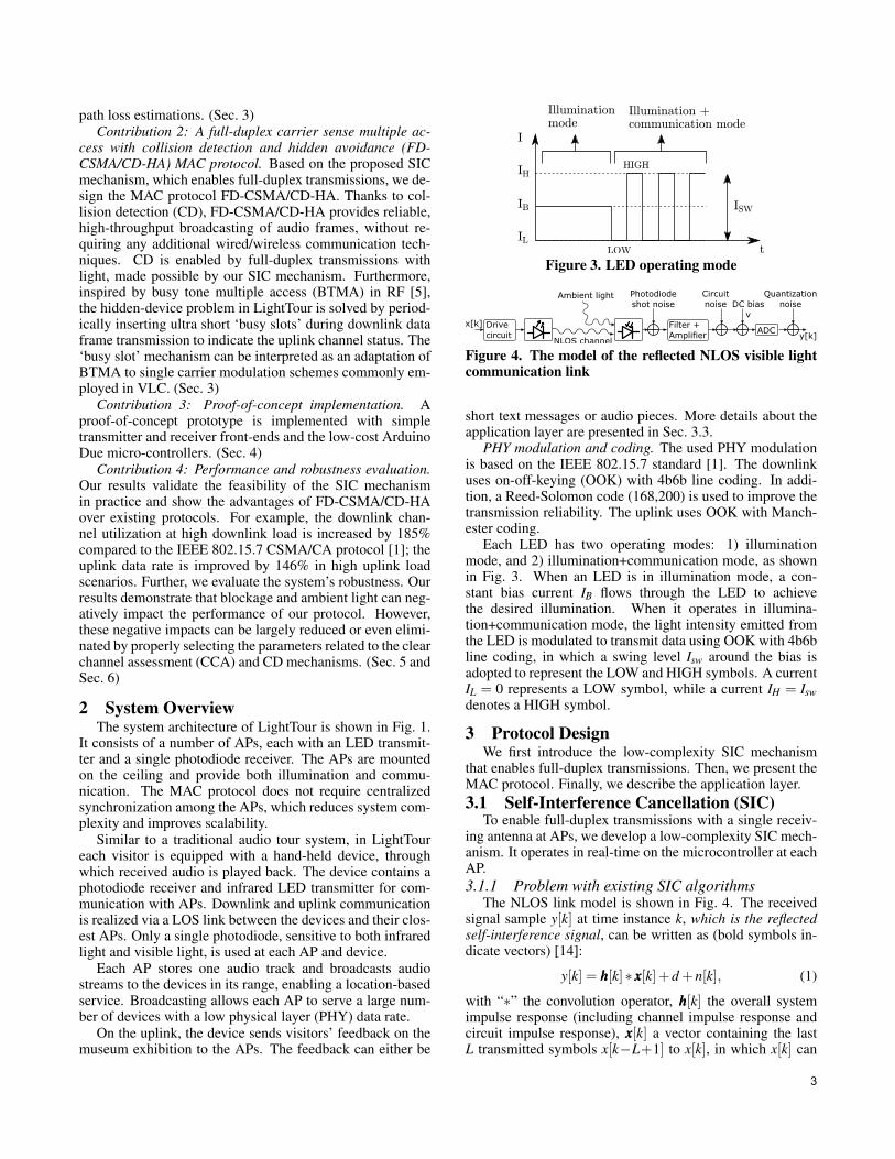
Figure 3. LED operating mode
Figure 4. The model of the reflected NLOS visible lightcommunication link
short text messages or audio pieces. More details about theapplication layer are presented in Sec. 3.3.
PHY modulation and coding. The used PHY modulationis based on the IEEE 802.15.7 standard [1]. The downlinkuses on-off-keying (OOK) with 4b6b line coding. In addi-tion, a Reed-Solomon code (168,200) is used to improve thetransmission reliability. The uplink uses OOK with Manch-ester coding.
Each LED has two operating modes: 1) illuminationmode, and 2) illumination+communication mode, as shownin Fig. 3. When an LED is in illumination mode, a con-stant bias current IB flows through the LED to achievethe desired illumination. When it operates in illumina-tion+communication mode, the light intensity emitted fromthe LED is modulated to transmit data using OOK with 4b6bline coding, in which a swing level Isw around the bias isadopted to represent the LOW and HIGH symbols. A currentIL = 0 represents a LOW symbol, while a current IH = Iswdenotes a HIGH symbol.
3 Protocol DesignWe first introduce the low-complexity SIC mechanism
that enables full-duplex transmissions. Then, we present theMAC protocol. Finally, we describe the application layer.3.1 Self-Interference Cancellation (SIC)
To enable full-duplex transmissions with a single receiv-ing antenna at APs, we develop a low-complexity SIC mech-anism. It operates in real-time on the microcontroller at eachAP.3.1.1 Problem with existing SIC algorithms
The NLOS link model is shown in Fig. 4. The receivedsignal sample y[k] at time instance k, which is the reflectedself-interference signal, can be written as (bold symbols in-dicate vectors) [14]:
y[k] = hhh[k]∗ xxx[k]+d +n[k], (1)
with “∗” the convolution operator, hhh[k] the overall systemimpulse response (including channel impulse response andcircuit impulse response), xxx[k] a vector containing the lastL transmitted symbols x[k−L+1] to x[k], in which x[k] can
3
be either -1 (LOW symbol in Fig. 3) or 1 (HIGH symbol)and L the length of the impulse response hhh[k]. Next, n[k]is the overall system noise (including photodiode shot noise,analog-to-digital converter (ADC) quantization noise, circuitthermal noise) and d the static direct current (DC) bias addedin the receiver circuit. The DC bias is added such that thevoltage at the ADC input falls approximately in the center ofthe ADC’s input voltage range.
In state-of-the-art digital SIC mechanisms, used in RFcommunication, hhh[k] is usually estimated adaptively on atraining sequence by using a recursive algorithm such as theleast-mean-squares algorithm [22]. However, from our mea-surements in Table 2 of Sec. 5, we observe that in embed-ded networks the computation time of least-mean-squares(update hhh[k] and compute output y[k]) and filter evaluation(compute y[k]) are 3.40 µs and 1.56 µs per symbol respec-tively. The targeted symbol duration of our system is 2µs, hence filter evaluation and least-mean-square calculationwould severely limit achievable data rate.
3.1.2 Our proposed low-complexity SICWe leverage the unique VLC channel characteristics to
simplify the computations and achieve real-time SIC. Wesplit the system impulse response hhh[k] in (1) into two parts:hhh[k] = hhhrrr · g[k]. The first part, hhhrrr, is a static vector (doesnot change over time) and is the normalized (DC gain=1)impulse response of the receiver circuit consisting of the fil-ter, amplifier and ADC. The second part, g[k], is a dynamicscalar (changes over time) and is the overall DC gain ofthe system which comprises the dynamic channel path losshc[k], static photodiode sensitivity and static receiver ampli-fier gain. In reality, the VLC channel has a multiple-tap im-pulse response hhhccc[k]. We approximate hhhccc[k] by a one-tappath loss hc[k], based on the observation that the root-mean-square delay spread of an indoor optical channel is ∼ 20 ns[14] and thus hhhccc[k] is much shorter than the target symboltime in our system (2 µs). Then (1) becomes:
y[k] = hhhrrr ∗ (g[k] · x[k])+d +n[k]. (2)
To compute the SIC in real-time in a microcontroller, we re-place hhhrrr with a static lookup-table T , trading time complex-ity for memory complexity. Let xu[k] be a unipolar repre-sentation (LOW=0, HIGH=1 instead of LOW=-1, HIGH=1)of x[k] and let xxxu[k] denote the binary concatenation ofthe vector that contains xu[k−L+1] to xu[k] (e.g., xxxu[k] =0b01010110011 for L = 11). We refer to L as the lookup-table order which is similar to the number of filter taps of hhhrrrreplaced by T . The AP then estimates y[k] using the follow-ing formula:
y[k] = Txxxu[[[kkk]]] · g[k] · x[k]+ d, (3)
in which y[k], g[k], and d denote estimates of y[k], g[k], and d,respectively. In addition, Txxxu[k] denotes the element at indexxxxu[k] in the lookup-table. At each time k, the index xxxu[k] isupdated recursively in software by right shifting xu[k] intoxxxu[k−1]:
xxxu[k] = (xxxu[k−1] << xu[k]) && 0x7FF (L = 11), (4)
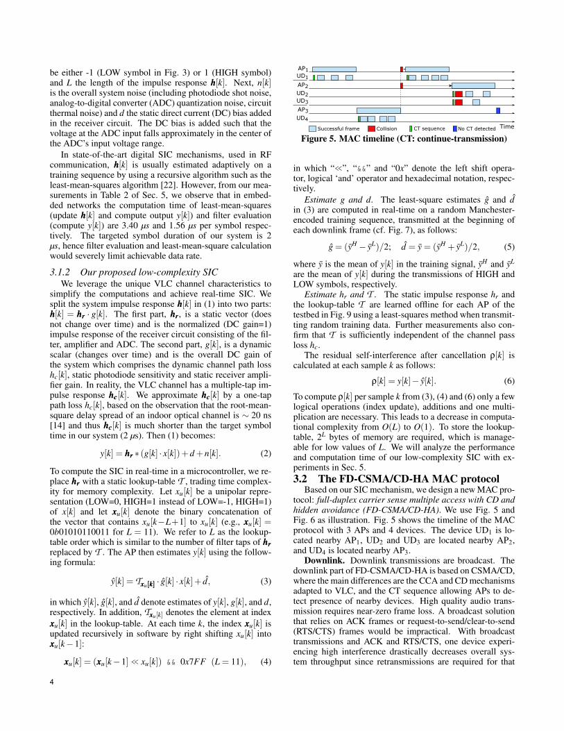
Figure 5. MAC timeline (CT: continue-transmission)
in which “<<”, “&&” and “0x” denote the left shift opera-tor, logical ‘and’ operator and hexadecimal notation, respec-tively.
Estimate g and d. The least-square estimates g and din (3) are computed in real-time on a random Manchester-encoded training sequence, transmitted at the beginning ofeach downlink frame (cf. Fig. 7), as follows:
g = (yH − yL)/2; d = y = (yH + yL)/2, (5)
where y is the mean of y[k] in the training signal, yH and yL
are the mean of y[k] during the transmissions of HIGH andLOW symbols, respectively.
Estimate hr and T . The static impulse response hr andthe lookup-table T are learned offline for each AP of thetestbed in Fig. 9 using a least-squares method when transmit-ting random training data. Further measurements also con-firm that T is sufficiently independent of the channel passloss hc.
The residual self-interference after cancellation ρ[k] iscalculated at each sample k as follows:
ρ[k] = y[k]− y[k]. (6)
To compute ρ[k] per sample k from (3), (4) and (6) only a fewlogical operations (index update), additions and one multi-plication are necessary. This leads to a decrease in computa-tional complexity from O(L) to O(1). To store the lookup-table, 2L bytes of memory are required, which is manage-able for low values of L. We will analyze the performanceand computation time of our low-complexity SIC with ex-periments in Sec. 5.3.2 The FD-CSMA/CD-HA MAC protocol
Based on our SIC mechanism, we design a new MAC pro-tocol: full-duplex carrier sense multiple access with CD andhidden avoidance (FD-CSMA/CD-HA). We use Fig. 5 andFig. 6 as illustration. Fig. 5 shows the timeline of the MACprotocol with 3 APs and 4 devices. The device UD1 is lo-cated nearby AP1, UD2 and UD3 are located nearby AP2,and UD4 is located nearby AP3.
Downlink. Downlink transmissions are broadcast. Thedownlink part of FD-CSMA/CD-HA is based on CSMA/CD,where the main differences are the CCA and CD mechanismsadapted to VLC, and the CT sequence allowing APs to de-tect presence of nearby devices. High quality audio trans-mission requires near-zero frame loss. A broadcast solutionthat relies on ACK frames or request-to-send/clear-to-send(RTS/CTS) frames would be impractical. With broadcasttransmissions and ACK and RTS/CTS, one device experi-encing high interference drastically decreases overall sys-tem throughput since retransmissions are required for that
4
device only. In addition, integrating ACK and RTS/CTS in abroadcast protocol is impractical since ACK and CTS framestransmitted from different devices would collide. The so-lution for broadcasting without frame loss due to collisionsis CD at each AP. Our FD-CSMA/CD-HA provides reliableaudio broadcasting since APs can detect detect and retrans-mit colliding frames. IEEE 802.15.7 CSMA/CA [1], on theother hand, has no CD, resulting in loss of colliding broad-cast frames.
Clear channel assessment. Before transmitting any data,each AP assesses if the downlink channel is busy by measur-ing the energy of Ncca samples. If the energy is greater than apredefined threshold (due to the detected NLOS signal), thena busy channel is declared.
Collision detection. It is performed on a random,Manchester-encoded training and test sequence with lengthLccd bytes transmitted at the start of each frame. The trainingsequence is used for DC channel gain g estimation. Duringthe transmission of the subsequent test sequence, the energyof the residual self-interference after cancellation signal ρ[k],as given in (6), is measured. If ρ[k] is greater than a prede-fined threshold, then a collision is declared.
Continue-transmission sequence. On the timeline inFig. 5, another feature of the downlink is shown. Each timea device receives the frame header, the device decides if itwants to receive the corresponding payload. If yes, the de-vice transmits a four-byte, random, Manchester encoded CTsequence using full-duplex transmission enabled in Sec. 3.1.The sequence is detected by the AP by measuring the energyin ρ[k]. When multiple devices send a random CT sequencein response to the same frame header, the random signals areadded at the AP receiver, which, using energy detection, al-lows the AP to detect that at least one device is present. TheCT sequence enables APs to abort transmitting the framepayload if no devices are present, leading to more efficientchannel usage and a reduction in power consumption at APs.
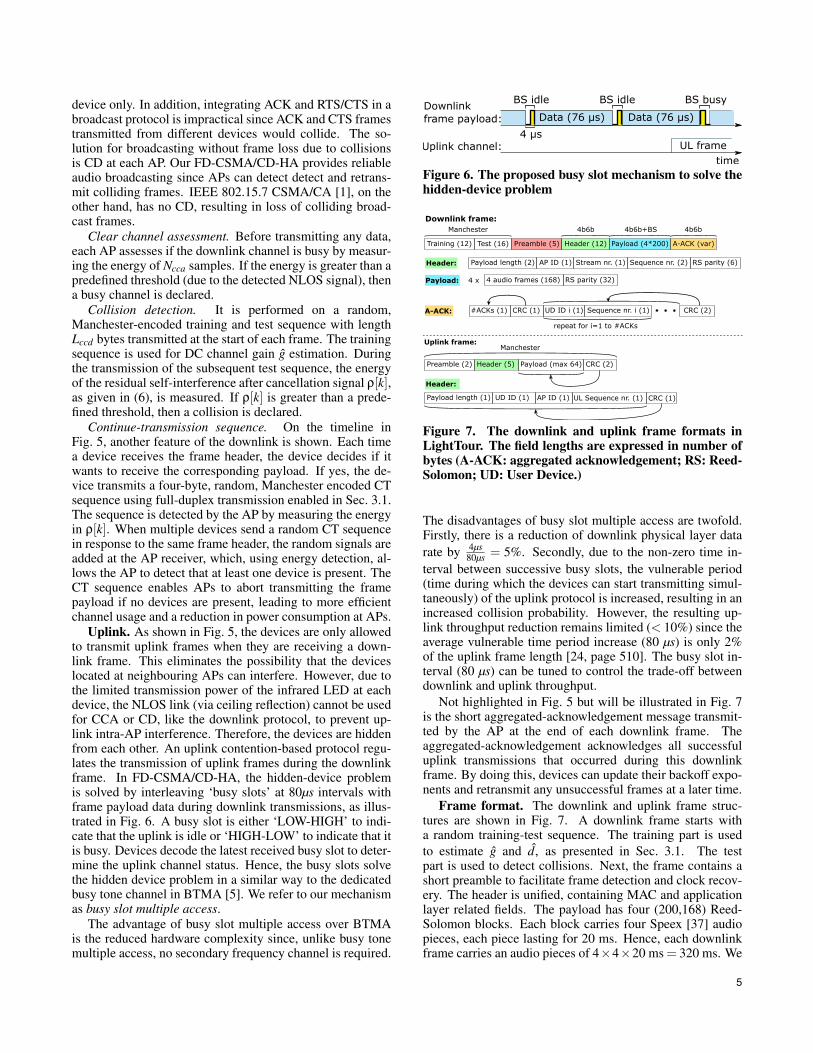
Uplink. As shown in Fig. 5, the devices are only allowedto transmit uplink frames when they are receiving a down-link frame. This eliminates the possibility that the deviceslocated at neighbouring APs can interfere. However, due tothe limited transmission power of the infrared LED at eachdevice, the NLOS link (via ceiling reflection) cannot be usedfor CCA or CD, like the downlink protocol, to prevent up-link intra-AP interference. Therefore, the devices are hiddenfrom each other. An uplink contention-based protocol regu-lates the transmission of uplink frames during the downlinkframe. In FD-CSMA/CD-HA, the hidden-device problemis solved by interleaving ‘busy slots’ at 80µs intervals withframe payload data during downlink transmissions, as illus-trated in Fig. 6. A busy slot is either ‘LOW-HIGH’ to indi-cate that the uplink is idle or ‘HIGH-LOW’ to indicate that itis busy. Devices decode the latest received busy slot to deter-mine the uplink channel status. Hence, the busy slots solvethe hidden device problem in a similar way to the dedicatedbusy tone channel in BTMA [5]. We refer to our mechanismas busy slot multiple access.
The advantage of busy slot multiple access over BTMAis the reduced hardware complexity since, unlike busy tonemultiple access, no secondary frequency channel is required.
Uplink channel:
Downlinkframe payload:
BS idle BS idle BS busy
time
Data (76 μs)
UL frame
Data (76 μs)
4 μs
Figure 6. The proposed busy slot mechanism to solve thehidden-device problem
Figure 7. The downlink and uplink frame formats inLightTour. The field lengths are expressed in number ofbytes (A-ACK: aggregated acknowledgement; RS: Reed-Solomon; UD: User Device.)
The disadvantages of busy slot multiple access are twofold.Firstly, there is a reduction of downlink physical layer datarate by 4µs
80µs = 5%. Secondly, due to the non-zero time in-terval between successive busy slots, the vulnerable period(time during which the devices can start transmitting simul-taneously) of the uplink protocol is increased, resulting in anincreased collision probability. However, the resulting up-link throughput reduction remains limited (< 10%) since theaverage vulnerable time period increase (80 µs) is only 2%of the uplink frame length [24, page 510]. The busy slot in-terval (80 µs) can be tuned to control the trade-off betweendownlink and uplink throughput.
Not highlighted in Fig. 5 but will be illustrated in Fig. 7is the short aggregated-acknowledgement message transmit-ted by the AP at the end of each downlink frame. Theaggregated-acknowledgement acknowledges all successfuluplink transmissions that occurred during this downlinkframe. By doing this, devices can update their backoff expo-nents and retransmit any unsuccessful frames at a later time.
Frame format. The downlink and uplink frame struc-tures are shown in Fig. 7. A downlink frame starts witha random training-test sequence. The training part is usedto estimate g and d, as presented in Sec. 3.1. The testpart is used to detect collisions. Next, the frame contains ashort preamble to facilitate frame detection and clock recov-ery. The header is unified, containing MAC and applicationlayer related fields. The payload has four (200,168) Reed-Solomon blocks. Each block carries four Speex [37] audiopieces, each piece lasting for 20 ms. Hence, each downlinkframe carries an audio pieces of 4×4×20 ms = 320 ms. We
5
encode the frame header with a short (12,6) Reed-Solomoncode, allowing devices to quickly decode the received head-ers and immediately respond with a CT sequence. An aggre-gated acknowledgement is appended to the end of the down-link frame and contains acknowledgements for all success-ful uplink frame transmissions during the current downlinkframe.
An uplink frame is much shorter compared to a down-link frame. The uplink frame contains a 2-byte preamble, aunified header with a 1-byte cyclic redundancy check (CRC)and a payload of up to 64 bytes with a 2-byte payload CRC.For the uplink, CRC is sufficient because uplink frame re-transmissions are possible and thus some uplink frame errorrate is acceptable. Thus, the more complex Reed-Solomoncode is not necessary (CRC requires 98% less computationtime compared to Reed-Solomon codes on our prototype).
3.3 Application LayerThe AP application layer broadcasts audio streams to de-
vices. Each AP stores a different audio track to providea location-based service. An audio stream is a series ofchronological audio frames corresponding to this AP’s audiotrack. A leaky bucket algorithm [29, page 407] is adoptedto provide both flow control and congestion control. Usingthe leaky bucket, each device has a small buffer correspond-ing to 4s of audio data. The first few frames of a stream aretransmitted quickly until the buffer (i.e. bucket) is full. Sub-sequent audio frames are transmitted at the same interval asthey are played back at the device. From our experiments,the congestion control provided by the leaky bucket mecha-nism also significantly increases the downlink fairness underhigh loads.
By default, an AP periodically (period of 1s) broadcastsshort probing frames. The payload of a probing frame cor-responds to the start of that AP’s audio track. Probing frametransmission is aborted when no CT sequence is detected.When a device wants to listen to the audio stream corre-sponding to a probing frame, it sends a CT sequence. TheCT sequence is sent for each subsequent frame belonging tothat stream. Transmission of further audio frames of a streamis aborted if no CT sequence is detected by the AP for twosubsequent frames of a stream.
A device tracks the RSSI of all frames (including prob-ing frames) it receives from all nearby APs. The device onlylistens to one stream from the AP with the highest RSSI.To avoid frequent switching when the device is at the edgebetween APs, a hysteresis mechanism similar to cellular sys-tems is employed [10].
The AP broadcasts audio streams to the devices in its cov-erage. That is, multiple devices can listen to the same audiostream. This allows each AP to serve a large number of de-vices with a low PHY data rate. When sufficient channel ca-pacity is available, an AP can transmit multiple (up to threein our prototype) audio streams in parallel, each of a differentpart of the audio track. If an AP is transmitting a stream andenough channel capacity is available, it additionally broad-casts probing frames to allow arriving users to open a newstream. Parallel streams hence allow a user, when arrivingat an AP, to quickly receive the start of an audio stream,
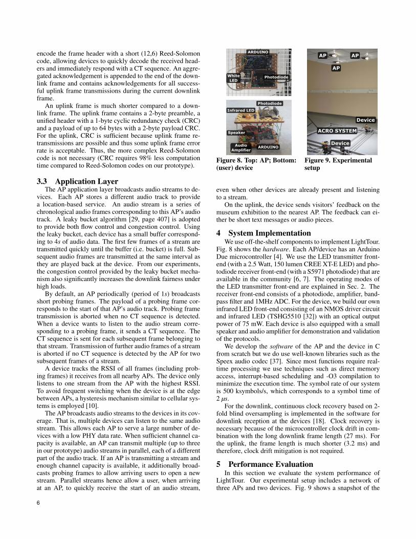
Figure 8. Top: AP; Bottom:(user) device
Figure 9. Experimentalsetup
even when other devices are already present and listeningto a stream.
On the uplink, the device sends visitors’ feedback on themuseum exhibition to the nearest AP. The feedback can ei-ther be short text messages or audio pieces.
4 System ImplementationWe use off-the-shelf components to implement LightTour.
Fig. 8 shows the hardware. Each AP/device has an ArduinoDue microcontroller [4]. We use the LED transmitter front-end (with a 2.5 Watt, 150 lumen CREE XT-E LED) and pho-todiode receiver front-end (with a S5971 photodiode) that areavailable in the community [6, 7]. The operating modes ofthe LED transmitter front-end are explained in Sec. 2. Thereceiver front-end consists of a photodiode, amplifier, band-pass filter and 1MHz ADC. For the device, we build our owninfrared LED front-end consisting of an NMOS driver circuitand infrared LED (TSHG5510 [32]) with an optical outputpower of 75 mW. Each device is also equipped with a smallspeaker and audio amplifier for demonstration and validationof the protocols.
We develop the software of the AP and the device in Cfrom scratch but we do use well-known libraries such as theSpeex audio codec [37]. Since most functions require real-time processing we use techniques such as direct memoryaccess, interrupt-based scheduling and -O3 compilation tominimize the execution time. The symbol rate of our systemis 500 ksymbols/s, which corresponds to a symbol time of2 µs.
For the downlink, continuous clock recovery based on 2-fold blind oversampling is implemented in the software fordownlink reception at the devices [18]. Clock recovery isnecessary because of the microcontroller clock drift in com-bination with the long downlink frame length (27 ms). Forthe uplink, the frame length is much shorter (3.2 ms) andtherefore, clock drift mitigation is not required.
5 Performance EvaluationIn this section we evaluate the system performance of
LightTour. Our experimental setup includes a network ofthree APs and two devices. Fig. 9 shows a snapshot of the
6
0 50 100 150Horizontal distance (cm)
10-4
10-2
100
Fra
me e
rror
rate
Downlink
Downlink, no CT
Downlink, no CT,
no CCR
Uplink
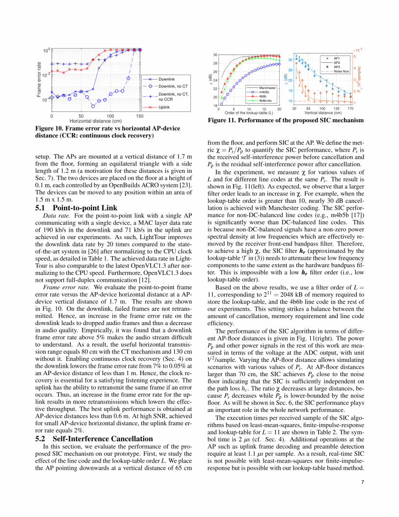
Figure 10. Frame error rate vs horizontal AP-devicedistance (CCR: continuous clock recovery)
setup. The APs are mounted at a vertical distance of 1.7 mfrom the floor, forming an equilateral triangle with a sidelength of 1.2 m (a motivation for these distances is given inSec. 7). The two devices are placed on the floor at a height of0.1 m, each controlled by an OpenBuilds ACRO system [23].The devices can be moved to any position within an area of1.5 m x 1.5 m.5.1 Point-to-point Link
Data rate. For the point-to-point link with a single APcommunicating with a single device, a MAC layer data rateof 190 kb/s in the downlink and 71 kb/s in the uplink areachieved in our experiments. As such, LightTour improvesthe downlink data rate by 20 times compared to the state-of-the-art system in [26] after normalizing to the CPU clockspeed, as detailed in Table 1. The achieved data rate in Light-Tour is also comparable to the latest OpenVLC1.3 after nor-malizing to the CPU speed. Furthermore, OpenVLC1.3 doesnot support full-duplex communication [12].
Frame error rate. We evaluate the point-to-point frameerror rate versus the AP-device horizontal distance at a AP-device vertical distance of 1.7 m. The results are shownin Fig. 10. On the downlink, failed frames are not retrans-mitted. Hence, an increase in the frame error rate on thedownlink leads to dropped audio frames and thus a decreasein audio quality. Empirically, it was found that a downlinkframe error rate above 5% makes the audio stream difficultto understand. As a result, the useful horizontal transmis-sion range equals 80 cm with the CT mechanism and 130 cmwithout it. Enabling continuous clock recovery (Sec. 4) onthe downlink lowers the frame error rate from 7% to 0.05% atan AP-device distance of less than 1 m. Hence, the clock re-covery is essential for a satisfying listening experience. Theuplink has the ability to retransmit the same frame if an erroroccurs. Thus, an increase in the frame error rate for the up-link results in more retransmissions which lowers the effec-tive throughput. The best uplink performance is obtained atAP-device distances less than 0.6 m. At high SNR, achievedfor small AP-device horizontal distance, the uplink frame er-ror rate equals 2%.5.2 Self-Interference Cancellation
In this section, we evaluate the performance of the pro-posed SIC mechanism on our prototype. First, we study theeffect of the line code and the lookup-table order L. We placethe AP pointing downwards at a vertical distance of 65 cm
0 5 10 15 20Order of the lookup-table (L)
18
20
22
24
26
28
30
(dB
)
Manchester
m4b5b
4b6b
4b6b+bs
30 65 100 135 170
Vertical distance (cm)
10
15
20
25
30
(d
B)
1
2
3
4
5
P (
V2/s
am
ple
)
10-3
AP1
AP2
AP3
Noise floor
Figure 11. Performance of the proposed SIC mechanism
from the floor, and perform SIC at the AP. We define the met-ric χ = Ps/Pρ to quantify the SIC performance, where Ps isthe received self-interference power before cancellation andPρ is the residual self-interference power after cancellation.
In the experiment, we measure χ for various values ofL and for different line codes at the same Ps. The result isshown in Fig. 11(left). As expected, we observe that a largerfilter order leads to an increase in χ. For example, when thelookup-table order is greater than 10, nearly 30 dB cancel-lation is achieved with Manchester coding. The SIC perfor-mance for non-DC-balanced line codes (e.g., m4b5b [17])is significantly worse than DC-balanced line codes. Thisis because non-DC-balanced signals have a non-zero powerspectral density at low frequencies which are effectively re-moved by the receiver front-end bandpass filter. Therefore,to achieve a high χ, the SIC filter hhhrrr (approximated by thelookup-table T in (3)) needs to attenuate these low frequencycomponents to the same extent as the hardware bandpass fil-ter. This is impossible with a low hhhrrr filter order (i.e., lowlookup-table order).
Based on the above results, we use a filter order of L =11, corresponding to 211 = 2048 kB of memory required tostore the lookup-table, and the 4b6b line code in the rest ofour experiments. This setting strikes a balance between theamount of cancellation, memory requirement and line codeefficiency.
The performance of the SIC algorithm in terms of differ-ent AP-floor distances is given in Fig. 11(right). The powerPρ and other power signals in the rest of this work are mea-sured in terms of the voltage at the ADC output, with unitV 2/sample. Varying the AP-floor distance allows simulatingscenarios with various values of Ps. At AP-floor distanceslarger than 70 cm, the SIC achieves Pρ close to the noisefloor indicating that the SIC is sufficiently independent onthe path loss hc. The ratio χ decreases at large distances, be-cause Ps decreases while Pρ is lower-bounded by the noisefloor. As will be shown in Sec. 6, the SIC performance playsan important role in the whole network performance.
The execution times per received sample of the SIC algo-rithms based on least-mean-squares, finite-impulse-responseand lookup-table for L = 11 are shown in Table 2. The sym-bol time is 2 µs (cf. Sec. 4). Additional operations at theAP such as uplink frame decoding and preamble detectionrequire at least 1.1 µs per sample. As a result, real-time SICis not possible with least-mean-squares nor finite-impulse-response but is possible with our lookup-table based method.
7
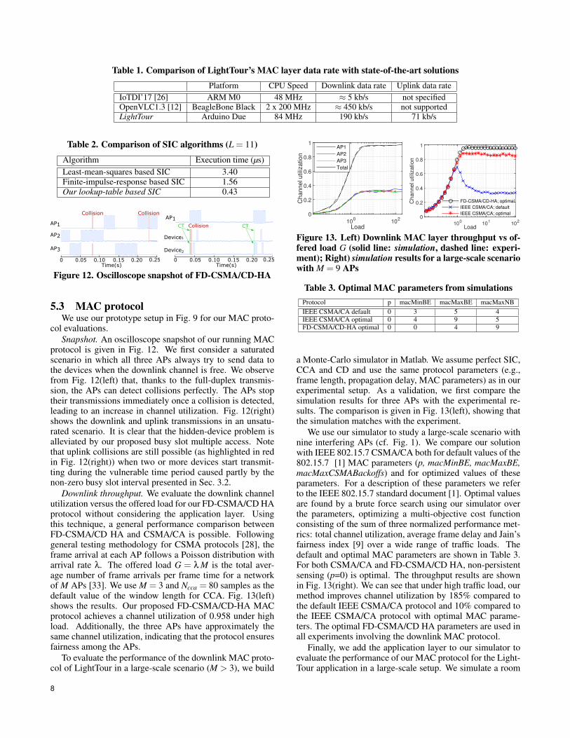
Table 1. Comparison of LightTour’s MAC layer data rate with state-of-the-art solutionsPlatform CPU Speed Downlink data rate Uplink data rate
IoTDI’17 [26] ARM M0 48 MHz ≈ 5 kb/s not specifiedOpenVLC1.3 [12] BeagleBone Black 2 x 200 MHz ≈ 450 kb/s not supportedLightTour Arduino Due 84 MHz 190 kb/s 71 kb/s
Table 2. Comparison of SIC algorithms (L = 11)
Algorithm Execution time (µs)Least-mean-squares based SIC 3.40Finite-impulse-response based SIC 1.56Our lookup-table based SIC 0.43
Figure 12. Oscilloscope snapshot of FD-CSMA/CD-HA
5.3 MAC protocolWe use our prototype setup in Fig. 9 for our MAC proto-
col evaluations.Snapshot. An oscilloscope snapshot of our running MAC
protocol is given in Fig. 12. We first consider a saturatedscenario in which all three APs always try to send data tothe devices when the downlink channel is free. We observefrom Fig. 12(left) that, thanks to the full-duplex transmis-sion, the APs can detect collisions perfectly. The APs stoptheir transmissions immediately once a collision is detected,leading to an increase in channel utilization. Fig. 12(right)shows the downlink and uplink transmissions in an unsatu-rated scenario. It is clear that the hidden-device problem isalleviated by our proposed busy slot multiple access. Notethat uplink collisions are still possible (as highlighted in redin Fig. 12(right)) when two or more devices start transmit-ting during the vulnerable time period caused partly by thenon-zero busy slot interval presented in Sec. 3.2.
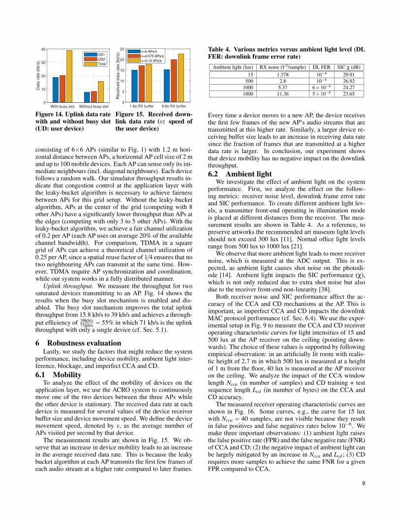
Downlink throughput. We evaluate the downlink channelutilization versus the offered load for our FD-CSMA/CD HAprotocol without considering the application layer. Usingthis technique, a general performance comparison betweenFD-CSMA/CD HA and CSMA/CA is possible. Followinggeneral testing methodology for CSMA protocols [28], theframe arrival at each AP follows a Poisson distribution witharrival rate λ. The offered load G = λ M is the total aver-age number of frame arrivals per frame time for a networkof M APs [33]. We use M = 3 and Ncca = 80 samples as thedefault value of the window length for CCA. Fig. 13(left)shows the results. Our proposed FD-CSMA/CD-HA MACprotocol achieves a channel utilization of 0.958 under highload. Additionally, the three APs have approximately thesame channel utilization, indicating that the protocol ensuresfairness among the APs.
To evaluate the performance of the downlink MAC proto-col of LightTour in a large-scale scenario (M > 3), we build
100
102
Load
0
0.2
0.4
0.6
0.8
1
Ch
an
ne
l u
tiliza
tio
n
AP1
AP2
AP3
Total
100
101
102
Load
0
0.2
0.4
0.6
0.8
1
Channel utiliz
ation
FD-CSMA/CD-HA; optimal
IEEE CSMA/CA; default
IEEE CSMA/CA; optimal
Figure 13. Left) Downlink MAC layer throughput vs of-fered load G (solid line: simulation, dashed line: experi-ment); Right) simulation results for a large-scale scenariowith M = 9 APs
Table 3. Optimal MAC parameters from simulationsProtocol p macMinBE macMaxBE macMaxNBIEEE CSMA/CA default 0 3 5 4IEEE CSMA/CA optimal 0 4 9 5FD-CSMA/CD-HA optimal 0 0 4 9
a Monte-Carlo simulator in Matlab. We assume perfect SIC,CCA and CD and use the same protocol parameters (e.g.,frame length, propagation delay, MAC parameters) as in ourexperimental setup. As a validation, we first compare thesimulation results for three APs with the experimental re-sults. The comparison is given in Fig. 13(left), showing thatthe simulation matches with the experiment.
We use our simulator to study a large-scale scenario withnine interfering APs (cf. Fig. 1). We compare our solutionwith IEEE 802.15.7 CSMA/CA both for default values of the802.15.7 [1] MAC parameters (p, macMinBE, macMaxBE,macMaxCSMABackoffs) and for optimized values of theseparameters. For a description of these parameters we referto the IEEE 802.15.7 standard document [1]. Optimal valuesare found by a brute force search using our simulator overthe parameters, optimizing a multi-objective cost functionconsisting of the sum of three normalized performance met-rics: total channel utilization, average frame delay and Jain’sfairness index [9] over a wide range of traffic loads. Thedefault and optimal MAC parameters are shown in Table 3.For both CSMA/CA and FD-CSMA/CD HA, non-persistentsensing (p=0) is optimal. The throughput results are shownin Fig. 13(right). We can see that under high traffic load, ourmethod improves channel utilization by 185% compared tothe default IEEE CSMA/CA protocol and 10% compared tothe IEEE CSMA/CA protocol with optimal MAC parame-ters. The optimal FD-CSMA/CD HA parameters are used inall experiments involving the downlink MAC protocol.
Finally, we add the application layer to our simulator toevaluate the performance of our MAC protocol for the Light-Tour application in a large-scale setup. We simulate a room
8
With busy slot Without busy slot0
10
20
30
40
Data
rate
(kb/s
)
UD1
UD2
Total
Figure 14. Uplink data ratewith and without busy slot(UD: user device)
1.6s RX buffer 9.6s RX buffer0
5
10
15
20
25
Re
ce
ive
d d
ata
ra
te (
kb
/s) v=0 APs/s
v=0.075 APs/s
v=0.13 APs/s
Figure 15. Received down-link data rate (v: speed ofthe user device)
consisting of 6×6 APs (similar to Fig. 1) with 1.2 m hori-zontal distance between APs, a horizontal AP cell size of 2 mand up to 100 mobile devices. Each AP can sense only its im-mediate neighbours (incl. diagonal neighbours). Each devicefollows a random walk. Our simulator throughput results in-dicate that congestion control at the application layer withthe leaky-bucket algorithm is necessary to achieve fairnessbetween APs for this grid setup. Without the leaky-bucketalgorithm, APs at the center of the grid (competing with 8other APs) have a significantly lower throughput than APs atthe edges (competing with only 3 to 5 other APs). With theleaky-bucket algorithm, we achieve a fair channel utilizationof 0.2 per AP (each AP uses on average 20% of the availablechannel bandwidth). For comparison, TDMA in a squaregrid of APs can achieve a theoretical channel utilization of0.25 per AP, since a spatial reuse factor of 1/4 ensures that notwo neighbouring APs can transmit at the same time. How-ever, TDMA require AP synchronization and coordination,while our system works in a fully distributed manner.
Uplink throughput. We measure the throughput for twosaturated devices transmitting to an AP. Fig. 14 shows theresults when the busy slot mechanism is enabled and dis-abled. The busy slot mechanism improves the total uplinkthroughput from 15.8 kb/s to 39 kb/s and achieves a through-put efficiency of 39kb/s
71kb/s = 55% in which 71 kb/s is the uplinkthroughput with only a single device (cf. Sec. 5.1).
6 Robustness evaluationLastly, we study the factors that might reduce the system
performance, including device mobility, ambient light inter-ference, blockage, and imperfect CCA and CD.6.1 Mobility
To analyze the effect of the mobility of devices on theapplication layer, we use the ACRO system to continuouslymove one of the two devices between the three APs whilethe other device is stationary. The received data rate at eachdevice is measured for several values of the device receiverbuffer size and device movement speed. We define the devicemovement speed, denoted by v, as the average number ofAPs visited per second by that device.
The measurement results are shown in Fig. 15. We ob-serve that an increase in device mobility leads to an increasein the average received data rate. This is because the leakybucket algorithm at each AP transmits the first few frames ofeach audio stream at a higher rate compared to later frames.
Table 4. Various metrics versus ambient light level (DLFER: downlink frame error rate)
Ambient light (lux) RX noise (V 2/sample) DL FER SIC χ (dB)15 1.378 10−4 29.91
500 2.8 10−4 26.921000 5.37 6×10⁻⁴ 24.271800 11.36 5×10⁻⁴ 23.65
Every time a device moves to a new AP, the device receivesthe first few frames of the new AP’s audio streams that aretransmitted at this higher rate. Similarly, a larger device re-ceiving buffer size leads to an increase in receiving data ratesince the fraction of frames that are transmitted at a higherdata rate is larger. In conclusion, our experiment showsthat device mobility has no negative impact on the downlinkthroughput.6.2 Ambient light
We investigate the effect of ambient light on the systemperformance. First, we analyze the effect on the follow-ing metrics: receiver noise level, downlink frame error rateand SIC performance. To create different ambient light lev-els, a transmitter front-end operating in illumination modeis placed at different distances from the receiver. The mea-surement results are shown in Table 4. As a reference, topreserve artworks the recommended art museum light levelsshould not exceed 300 lux [11]. Normal office light levelsrange from 500 lux to 1000 lux [21].
We observe that more ambient light leads to more receivernoise, which is measured at the ADC output. This is ex-pected, as ambient light causes shot noise on the photodi-ode [14]. Ambient light impacts the SIC performance (χ),which is not only reduced due to extra shot noise but alsodue to the receiver front-end non-linearity [38].
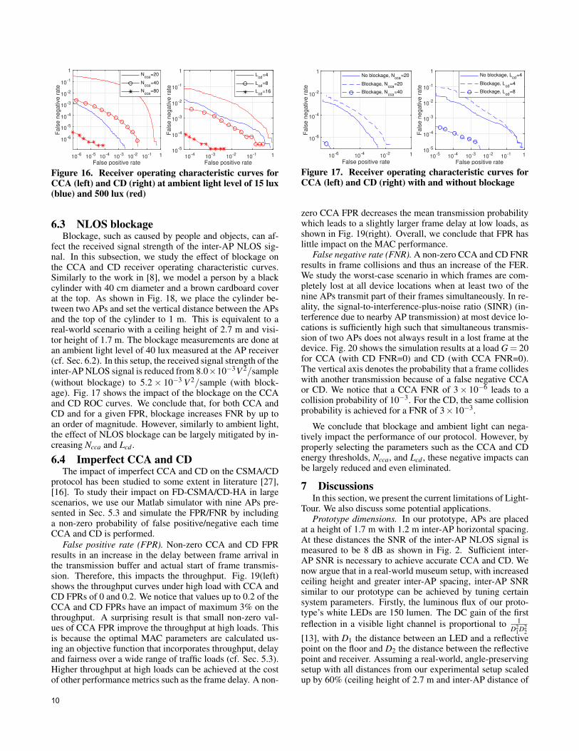
Both receiver noise and SIC performance affect the ac-curacy of the CCA and CD mechanisms at the AP. This isimportant, as imperfect CCA and CD impacts the downlinkMAC protocol performance (cf. Sec. 6.4). We use the exper-imental setup in Fig. 9 to measure the CCA and CD receiveroperating characteristic curves for light intensities of 15 and500 lux at the AP receiver on the ceiling (pointing down-wards). The choice of these values is supported by followingempirical observation: in an artificially lit room with realis-tic height of 2.7 m in which 500 lux is measured at a heightof 1 m from the floor, 40 lux is measured at the AP receiveron the ceiling. We analyze the impact of the CCA windowlength Ncca (in number of samples) and CD training + testsequence length Lcd (in number of bytes) on the CCA andCD accuracy.
The measured receiver operating characteristic curves areshown in Fig. 16. Some curves, e.g., the curve for 15 luxwith Ncca = 40 samples, are not visible because they resultin false positives and false negatives rates below 10−6. Wemake three important observations: (1) ambient light raisesthe false positive rate (FPR) and the false negative rate (FNR)of CCA and CD; (2) the negative impact of ambient light canbe largely mitigated by an increase in Ncca and Lcd ; (3) CDrequires more samples to achieve the same FNR for a givenFPR compared to CCA.
9
10-6
10-5
10-4
10-3
10-2
10-1 1
False positive rate
10-6
10-5
10-4
10-3
10-2
10-1
1
Fals
e n
egative r
ate
Ncca
=20
Ncca
=40
Ncca
=80
10-4
10-3
10-2
10-1 1
False positive rate
10-5
10-4
10-3
10-2
10-1
1
Fals
e n
egative r
ate
Lcd
=4
Lcd
=8
Lcd
=16
Figure 16. Receiver operating characteristic curves forCCA (left) and CD (right) at ambient light level of 15 lux(blue) and 500 lux (red)
6.3 NLOS blockageBlockage, such as caused by people and objects, can af-
fect the received signal strength of the inter-AP NLOS sig-nal. In this subsection, we study the effect of blockage onthe CCA and CD receiver operating characteristic curves.Similarly to the work in [8], we model a person by a blackcylinder with 40 cm diameter and a brown cardboard coverat the top. As shown in Fig. 18, we place the cylinder be-tween two APs and set the vertical distance between the APsand the top of the cylinder to 1 m. This is equivalent to areal-world scenario with a ceiling height of 2.7 m and visi-tor height of 1.7 m. The blockage measurements are done atan ambient light level of 40 lux measured at the AP receiver(cf. Sec. 6.2). In this setup, the received signal strength of theinter-AP NLOS signal is reduced from 8.0×10⁻³V 2/sample(without blockage) to 5.2 × 10⁻³ V 2/sample (with block-age). Fig. 17 shows the impact of the blockage on the CCAand CD ROC curves. We conclude that, for both CCA andCD and for a given FPR, blockage increases FNR by up toan order of magnitude. However, similarly to ambient light,the effect of NLOS blockage can be largely mitigated by in-creasing Ncca and Lcd .
6.4 Imperfect CCA and CDThe impact of imperfect CCA and CD on the CSMA/CD
protocol has been studied to some extent in literature [27],[16]. To study their impact on FD-CSMA/CD-HA in largescenarios, we use our Matlab simulator with nine APs pre-sented in Sec. 5.3 and simulate the FPR/FNR by includinga non-zero probability of false positive/negative each timeCCA and CD is performed.
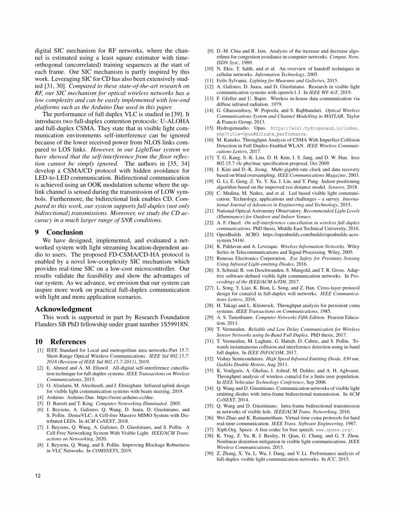
False positive rate (FPR). Non-zero CCA and CD FPRresults in an increase in the delay between frame arrival inthe transmission buffer and actual start of frame transmis-sion. Therefore, this impacts the throughput. Fig. 19(left)shows the throughput curves under high load with CCA andCD FPRs of 0 and 0.2. We notice that values up to 0.2 of theCCA and CD FPRs have an impact of maximum 3% on thethroughput. A surprising result is that small non-zero val-ues of CCA FPR improve the throughput at high loads. Thisis because the optimal MAC parameters are calculated us-ing an objective function that incorporates throughput, delayand fairness over a wide range of traffic loads (cf. Sec. 5.3).Higher throughput at high loads can be achieved at the costof other performance metrics such as the frame delay. A non-
10-6
10-4
10-2 1
False positive rate
10-6
10-4
10-2
1
Fa
lse
ne
ga
tive
ra
te
No blockage, Ncca
=20
Blockage, Ncca
=20
Blockage, Ncca
=40
10-5
10-4
10-3
10-2
10-1 1
False positive rate
10-5
10-4
10-3
10-2
10-1
1
Fa
lse
ne
ga
tive
ra
te
No blockage, Lcd
=4
Blockage, Lcd
=4
Blockage, Lcd
=8
Figure 17. Receiver operating characteristic curves forCCA (left) and CD (right) with and without blockage
zero CCA FPR decreases the mean transmission probabilitywhich leads to a slightly larger frame delay at low loads, asshown in Fig. 19(right). Overall, we conclude that FPR haslittle impact on the MAC performance.
False negative rate (FNR). A non-zero CCA and CD FNRresults in frame collisions and thus an increase of the FER.We study the worst-case scenario in which frames are com-pletely lost at all device locations when at least two of thenine APs transmit part of their frames simultaneously. In re-ality, the signal-to-interference-plus-noise ratio (SINR) (in-terference due to nearby AP transmission) at most device lo-cations is sufficiently high such that simultaneous transmis-sion of two APs does not always result in a lost frame at thedevice. Fig. 20 shows the simulation results at a load G = 20for CCA (with CD FNR=0) and CD (with CCA FNR=0).The vertical axis denotes the probability that a frame collideswith another transmission because of a false negative CCAor CD. We notice that a CCA FNR of 3× 10⁻⁶ leads to acollision probability of 10−3. For the CD, the same collisionprobability is achieved for a FNR of 3×10⁻³.
We conclude that blockage and ambient light can nega-tively impact the performance of our protocol. However, byproperly selecting the parameters such as the CCA and CDenergy thresholds, Ncca, and Lcd , these negative impacts canbe largely reduced and even eliminated.
7 DiscussionsIn this section, we present the current limitations of Light-
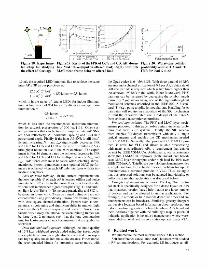
Tour. We also discuss some potential applications.Prototype dimensions. In our prototype, APs are placed
at a height of 1.7 m with 1.2 m inter-AP horizontal spacing.At these distances the SNR of the inter-AP NLOS signal ismeasured to be 8 dB as shown in Fig. 2. Sufficient inter-AP SNR is necessary to achieve accurate CCA and CD. Wenow argue that in a real-world museum setup, with increasedceiling height and greater inter-AP spacing, inter-AP SNRsimilar to our prototype can be achieved by tuning certainsystem parameters. Firstly, the luminous flux of our proto-type’s white LEDs are 150 lumen. The DC gain of the firstreflection in a visible light channel is proportional to 1
D21D2
2[13], with D1 the distance between an LED and a reflectivepoint on the floor and D2 the distance between the reflectivepoint and receiver. Assuming a real-world, angle-preservingsetup with all distances from our experimental setup scaledup by 60% (ceiling height of 2.7 m and inter-AP distance of
10
1.2m
1m
1.7m
Figure 18. Experimen-tal setup for studyingthe effect of blockage
100
101
102
Load (attempts/frame)
0.92
0.93
0.94
0.95
0.96
0.97
Ch
an
ne
l u
tiliz
atio
n
CCA FPR=0; CD FPR=0
CCA FPR=0.2; CD FPR=0
CCA FPR=0; CD FPR=0.2
CCA FPR=0.2; CD FPR=0.2
0.1 0.2 0.3
Load (attempts/frame)
50
100
150
200
250
300
Me
an
fra
me
de
lay (
s)
Figure 19. Result of the FPR of CCA and CD: left) down-link MAC throughput vs offered load; Right) downlinkMAC mean frame delay vs offered load
10-6 10-4 10-2 100
False negative rate
10-5
10-3
10-1
Co
llisio
n p
rob
ab
ility
CCA
CD
Figure 20. Worst-case collisionprobability versus CCA and CDFNR for load G = 20
1.9 m), the required LED luminous flux to achieve the sameinter-AP SNR as our prototype is:
(2.7m)2(2.7m)2
(1.7m)2(1.7m)2 ×150 lumen = 954 lumen,
which is in the range of regular LEDs for indoor illumina-tion. A luminance of 954 lumen results in an average roomillumination of:
954 lumen(1.9m)2 = 272 lux,
which is less than the recommended maximum illumina-tion for artwork preservation of 300 lux [11]. Other sys-tem parameters that can be tuned to improve inter-AP SNRare floor reflectivity, AP horizontal spacing and LED halfpower semi-angle. Finally, if the inter-AP SNR is still insuf-ficient, increasing Ncca and Lcd significantly decreases FPRand FNR for CCA and CCD at the cost of limited (< 5%)throughput reduction due to the extra overhead. The exper-iment in Fig. 16 demonstrates the achieved decrease in FPRand FNR for CCA and CD for multiple values of Ncca andLcd . Additional care must be taken when selecting above-mentioned system parameters since optimal MAC perfor-mance is obtained when each AP only interferes with its im-mediate neighbors.
Look-up table training. In the current implementation,the look-up table T of each AP is learned offline and henceimmutable. SIC close to the noise floor is achieved undervarious self-interference signal strengths (Fig. 11 and ambi-ent light levels (Table 4). To increase practicality and SIC ro-bustness, in future work, T can be trained online on each mi-crocontroller using periodically transmitted training frameswith least-square channel estimation. Factors such as tem-perature, circuit aging and significant shifts in ambient lightcan affect the RX circuit response and hence T . Since thesefactors vary slowly, the interval between training frames canbe large (e.g., 2 minutes), such that the long computationtime for least-squares channel estimation (3.4 µs/symbol) isirrelevant.
Data rate and audio quality. Although the audio qualityof 16.8 kb/s wideband speech coded using the Speex codecis acceptable, a museum might also be interested to incorpo-rate high quality music into the audio streams. For example,the recommended bitrate for streaming stereo music with
the Opus codec is 64 kb/s [15]. With three parallel 64 kb/sstreams and a channel utilization of 0.2 per AP, a data rate of960 kb/s per AP is required which is five times higher thanthe achieved 190 kb/s in this work. In our future work, PHYdata rate can be increased by decreasing the symbol length(currently 2 µs) and/or using one of the higher-throughputmodulation schemes described in the IEEE 802.15.7 stan-dard [1] (e.g., pulse amplitude modulation). Handling fasterdata rates will require an adaptation of the SIC mechanismto limit the excessive table size, a redesign of the TX/RXfront-ends and faster microcontrollers.
Protocol applicability. The PHY and MAC layer mech-anisms proposed in this paper solve certain universal prob-lems that harm VLC systems. Firstly, the SIC mecha-nism enables full-duplex transmission with only a singleoptical antenna and enables the CD mechanism neededfor CSMA/CD. Secondly, the proposed CSMA/CD pro-tocol is novel for VLC and allows reliable broadcastingwith many uncoordinated APs, a requirement that cannotbe met by IEEE CSMA/CA. Additionally, our experimentsshow that CSMA/CD improves (both unicast and broad-cast) MAC-layer throughput under high load by 10% overIEEE CSMA/CA. Thirdly, the busy slot mechanism providesa simple solution to the hidden device problem for uplinktransmissions, a common problem in VLC. Thus, we arguethat our proposed solutions can be adopted individually, orcollectively in other applications as discussed below.
Examples of similar applications. The LightTour proto-col stack is specifically designed for a dense layout of APsthat broadcast location-based information to a large numberof devices and can be adopted to similar applications. Forexample, in airports or train stations departure times and an-nouncements can be broadcast. Similarly, grocery shopperscan receive location-based information about products. Anindoor positioning system is feasible where APs broadcasttheir locations together with the building’s map. A potentialindustrial application is inventory management where ware-house shelves send and receive status updates using VLC.
8 Related workWe summarize the most relevant works in this section.Self-interference cancellation (SIC) has been well-studied
in RF communications. For example, [2] introduces an all-
11
digital SIC mechanism for RF networks, where the chan-nel is estimated using a least square estimator with time-orthogonal (uncorrelated) training sequences at the start ofeach frame. Our SIC mechanism is partly inspired by thiswork. Leveraging SIC for CD has also been extensively stud-ied [31, 30]. Compared to these state-of-the-art research onRF, our SIC mechanism for optical wireless networks has alow complexity and can be easily implemented with low-endplatforms such as the Arduino Due used in this paper.
The performance of full duplex VLC is studied in [39]. Itintroduces two full-duplex contention protocols: U-ALOHAand full-duplex CSMA. They state that in visible light com-munication environments self-interference can be ignoredbecause of the lower received power from NLOS links com-pared to LOS links. However, in our LightTour system wehave showed that the self-interference from the floor reflec-tion cannot be simply ignored. The authors in [35, 34]develop a CSMA/CD protocol with hidden avoidance forLED-to-LED communication. Bidirectional communicationis achieved using an OOK modulation scheme where the up-link channel is sensed during the transmission of LOW sym-bols. Furthermore, the bidirectional link enables CD. Com-pared to this work, our system supports full-duplex (not onlybidirectional) transmissions. Moreover, we study the CD ac-curacy in a much larger range of SNR conditions.
9 ConclusionWe have designed, implemented, and evaluated a net-
worked system with light streaming location-dependent au-dio to users. The proposed FD-CSMA/CD-HA protocol isenabled by a novel low-complexity SIC mechanism whichprovides real-time SIC on a low-cost microcontroller. Ourresults validate the feasibility and show the advantages ofour system. As we advance, we envision that our system caninspire more work on practical full-duplex communicationwith light and more application scenarios.
AcknowledgmentThis work is supported in part by Research Foundation
Flanders SB PhD fellowship under grant number 1S59918N.
10 References[1] IEEE Standard for Local and metropolitan area networks-Part 15.7:
Short-Range Optical Wireless Communications. IEEE Std 802.15.7-2018 (Revision of IEEE Std 802.15.7-2011), 2019.
[2] E. Ahmed and A. M. Eltawil. All-digital self-interference cancella-tion technique for full-duplex systems. IEEE Transactions on WirelessCommunications, 2015.
[3] O. Alsulami, M. Alresheedi, and J. Elmirghani. Infrared uplink designfor visible light communication systems with beam steering, 2019.
[4] Arduino. Arduino Due. https://store.arduino.cc/due.[5] D. Barrett and T. King. Computer Networking Illuminated. 2005.[6] J. Beysens, A. Galisteo, Q. Wang, D. Juara, D. Giustiniano, and
S. Pollin. DenseVLC: A Cell-free Massive MIMO System with Dis-tributed LEDs. In ACM CoNEXT, 2018.
[7] J. Beysens, Q. Wang, A. Galisteo, D. Giustiniano, and S. Pollin. ACell-Free Networking System With Visible Light. IEEE/ACM Trans-actions on Networking, 2020.
[8] J. Beysens, Q. Wang, and S. Pollin. Improving Blockage Robustnessin VLC Networks. In COMSNETS, 2019.
[9] D.-M. Chiu and R. Jain. Analysis of the increase and decrease algo-rithms for congestion avoidance in computer networks. Comput. Netw.ISDN Syst., 1989.
[10] N. Ekiz, T. Salih, and et al. An overview of handoff techniques incellular networks. Information Technology, 2005.
[11] Feilo Sylvania. Lighting for Museums and Galleries, 2015.[12] A. Galisteo, D. Juara, and D. Giustiniano. Research in visible light
communication systems with openvlc1.3. In IEEE WF-IoT, 2019.[13] F. Gfeller and U. Bapst. Wireless in-house data communication via
diffuse infrared radiation. 1979.[14] G. Ghassemlooy, W. Popoola, and S. Rajbhandari. Optical Wireless
Communications System and Channel Modelling in MATLAB. Taylor& Francis Group, 2013.
[15] Hydrogenaudio. Opus. https://wiki.hydrogenaud.io/index.php?title=Opus#Bitrate_performance.
[16] M. Kaneko. Throughput Analysis of CSMA With Imperfect CollisionDetection in Full Duplex-Enabled WLAN. IEEE Wireless Communi-cations Letters, 2017.
[17] T. G. Kang, S.-K. Lim, D. H. Kim, I. S. Jang, and D. W. Han. Ieee802.15.7 vlc phy/mac specification proposal, Oct 2009.
[18] J. Kim and D.-K. Jeong. Multi-gigabit-rate clock and data recoverybased on blind oversampling. IEEE Communications Magazine, 2003.
[19] G. Li, E. Geng, Z. Ye, Y. Xu, J. Lin, and Y. Pang. Indoor positioningalgorithm based on the improved rssi distance model. Sensors, 2018.
[20] C. Medina, M. Nunez, and et al. Led based visible light communi-cation: Technology, applications and challenges – a survey. Interna-tional Journal of Advances in Engineering and Technology, 2015.
[21] National Optical Astronomy Observatory. Recommended Light Levels(Illuminance) for Outdoor and Indoor Venues.
[22] A. F. Oncel. On self-interference cancellation in wireless full duplexcommunications. PhD thesis, Middle East Technical University, 2016.
[23] OpenBuilds. ACRO. https://openbuilds.com/builds/openbuilds-acro-system.5416/.
[24] K. Pahlavan and A. Levesque. Wireless Information Networks. WileySeries in Telecommunications and Signal Processing. Wiley, 2005.
[25] Renesas Electronics Corporation. Eye Safety for Proximity SensingUsing Infrared Light-emitting Diodes, 2016.
[26] S. Schmid, B. von Deschwanden, S. Mangold, and T. R. Gross. Adap-tive software-defined visible light communication networks. In Pro-ceedings of the IEEE/ACM IoTDI, 2017.
[27] L. Song, Y. Liao, K. Bian, L. Song, and Z. Han. Cross-layer protocoldesign for csma/cd in full-duplex wifi networks. IEEE Communica-tions Letters, 2016.
[28] H. Takagi and L. Kleinrock. Throughput analysis for persistent csmasystems. IEEE Transactions on Communications, 1985.
[29] A. S. Tanenbaum. Computer Networks Fifth Edition. Pearson Educa-tion, 2011.
[30] T. Vermeulen. Reliable and Low Delay Communication for WirelessSensor Networks using In-Band Full Duplex. PhD thesis, 2017.
[31] T. Vermeulen, M. Laghate, G. Hattab, D. Cabric, and S. Pollin. To-wards instantaneous collision and interference detection using in-bandfull duplex. In IEEE INFOCOM, 2017.
[32] Vishay Semicondutors. High Speed Infrared Emitting Diode, 830 nm,GaAlAs Double Hetero, Aug 2011.
[33] K. Voulgaris, A. Gkelias, I. Ashraf, M. Dohler, and A. H. Aghvami.Throughput analysis of wireless csma/cd for a finite user population.In IEEE Vehicular Technology Conference, Sep 2006.
[34] Q. Wang and D. Giustiniano. Communication networks of visible lightemitting diodes with intra-frame bidirectional transmission. In ACMCoNEXT, 2014.
[35] Q. Wang and D. Giustiniano. Intra-frame bidirectional transmissionin networks of visible leds. IEEE/ACM Trans. Networking, 2016.
[36] Wei Zhao and K. Ramamritham. Virtual time csma protocols for hardreal-time communication. IEEE Trans. Software Engineering, 1987.
[37] Xiph.Org. Speex: A free codec for free speech. www.speex.org/.[38] K. Ying, Z. Yu, R. J. Baxley, H. Qian, G. Chang, and G. T. Zhou.
Nonlinear distortion mitigation in visible light communications. IEEEWireless Communications, 2015.
[39] Z. Zhang, X. Yu, L. Wu, J. Dang, and V. Li. Performance analysis offull-duplex visible light communication networks. In ICC, 2015.
12