LG Design and Integration into Aircraft - ingaero.uniroma1.it presentation - LG... · Landing Gear...
29
LG Design and Integration into Aircraft November 2016 Landing Gear Design and Integration into Aircraft Sapienza University, Adriano Argiolas LG Flight Physics Integration
Transcript of LG Design and Integration into Aircraft - ingaero.uniroma1.it presentation - LG... · Landing Gear...

LG Design and Integration into Aircraft
November 2016Landing Gear Design and Integration into Aircraft
Sapienza University, Adriano Argiolas
LG Flight Physics Integration

© AIRBUS Operations LTD. All rights reserved. Confidential and proprietary document.
What’s a Landing Gear?
November 2016Landing Gear Design and Integration into Aircraft
“The essential intermediary between the aeroplane and the catastrophe”Conway, H. G., Landing Gear Design, Chapman & Hall, London, 1958
© AIRBUS Operations LTD. All rights reserved. Confidential and proprietary document.
A bit of terminology
November 2016Landing Gear Design and Integration into Aircraft
Nose landing gear Main landing gear

© AIRBUS Operations LTD. All rights reserved. Confidential and proprietary document.
What does a landing gear do
Airbus A380
MTOW 575 tT/O speed: 277 km/hLanding speed: 240 km/h
Landing distance 1900m @ 386tOperating Temperature -50˚C to +70˚C
November 2016Landing Gear Design and Integration into Aircraft
US Class 8 truck
MTOW 36 t Stopping distance 102 m @ 96 km/h:
F1 car
ZFW 0.702 tTop speed in 2016: 372.54* km/hOperating Temperature +5˚C** to +38˚C***
* 2016 Mexico Grand Prix – V Bottas
**1978 Canadian Grand Prix
***1984 Dallas Grand Prix

© AIRBUS Operations LTD. All rights reserved. Confidential and proprietary document.
Landing gear design
November 2016Landing Gear Design and Integration into Aircraft

© AIRBUS Operations LTD. All rights reserved. Confidential and proprietary document.
LG design objectives
November 2016Landing Gear Design and Integration into Aircraft
• Safety• Landing gear is designed to be safe life • Max strength & min weight
• High reliability & low cost
• A/C integration & airport compatibility
• Low maintenance
The final scope is not to design the best landing gear, but to design the best overall aircraft

© AIRBUS Operations LTD. All rights reserved. Confidential and proprietary document.
Configuration definition
TailwheelPros• Simplicity
• A/C is tilted to high AoA, providing improving lift at TO and higher clearance for propeller engine
Cons• Intrinsically instable
November 2016Landing Gear Design and Integration into Aircraft
Nose wheel tricyclePros• Fuselage (and cabin/cargo floor) are nearly level
• Improved stability during braking and manoeuvres
• Pitch-down moment at landing, reduces AoA and lift
Cons• Gears locations are more constrained

© AIRBUS Operations LTD. All rights reserved. Confidential and proprietary document.
Tailwheel gear ground loop
November 2016Landing Gear Design and Integration into Aircraft
Video: tailwheel gear ground loop

© AIRBUS Operations LTD. All rights reserved. Confidential and proprietary document.
Where to put the LG?
• NLG and MLG must be placed far enough from the A/C CG such that there is no risk of tipping back or turning over under any static or dynamic condition
• In order to guarantee the braking performance, MLG should support between 85% and 92% of the A/C weight
• A/C loadability must be taken into account
November 2016Landing Gear Design and Integration into Aircraft
Components cg envelopes

© AIRBUS Operations LTD. All rights reserved. Confidential and proprietary document.
November 2016Landing Gear Design and Integration into Aircraft
Aircraft loadability
Loadability issue on cargo aircraft

© AIRBUS Operations LTD. All rights reserved. Confidential and proprietary document.
Geometry definition
November 2016Landing Gear Design and Integration into Aircraft
• The available pitch at TO and Landing must be ≥ the value imposed by A/C performance requirement. If this is not respected, the consequence would be a reduction in minimum liftoff speed and/or operations in crosswind
• The A/C height on the groundline is also determined by the engine to ground clearance and the LG doors to ground clearance
Tail clearance Wing clearance

© AIRBUS Operations LTD. All rights reserved. Confidential and proprietary document.
Crosswind landing – Low speed takeoff
November 2016Landing Gear Design and Integration into Aircraft
Crosswind one-wheel landing
Video: A340 low-speed takeoff

© AIRBUS Operations LTD. All rights reserved. Confidential and proprietary document.
Flotation
• Airports charge airlines based on ACN (Aircraft Classification Number)
• ACN takes in account MTOW, LG configuration, CG position and runway pavement type
• Modifying the number of tyres and the wheelbase has an effect on ACN, and can do the difference on whether an A/C can or cannot land in a specific airport
November 2016Landing Gear Design and Integration into Aircraft

© AIRBUS Operations LTD. All rights reserved. Confidential and proprietary document.
November 2016Landing Gear Design and Integration into Aircraft
Runway (in)compatibility
Aircraft/runway loading incopatibility

© AIRBUS Operations LTD. All rights reserved. Confidential and proprietary document.
Tyres
• Tyres are not tailored to a specific A/C. Tyre selection is based on the simple requirement that its load and speed rating must be compatible with the AC characteristics
• Load transfer between LG and ground is heavily dependent from tyre characteristics
• Tyre behaviour is highly nonlinear
• LG design must cater for the possibility to have a non homogeneous set of tyres on any gear
November 2016Landing Gear Design and Integration into Aircraft

© AIRBUS Operations LTD. All rights reserved. Confidential and proprietary document.
November 2016Landing Gear Design and Integration into Aircraft
Side loads on tyres
Brake pivot turn

© AIRBUS Operations LTD. All rights reserved. Confidential and proprietary document.
Brakes and wheels
• Brakes are used to stop and steer the AC
• Brake sizing depends directly upon the AC performance
• Wheel design is driven primarily by its requirement to accommodate the required tyre and to house the brake while retaining minimum weight and maximum life
November 2016Landing Gear Design and Integration into Aircraft
Wheel and brake cutout

© AIRBUS Operations LTD. All rights reserved. Confidential and proprietary document.
“Square” tyre
November 2016Landing Gear Design and Integration into Aircraft
Buckled deflated tyre

© AIRBUS Operations LTD. All rights reserved. Confidential and proprietary document.
Brakes instabilities
• Squeal vibration is characterized by torsional motion of stators, torque tube, and piston housing. Typical frequency range is between 100 Hz and 20 kHz
• Whirl vibration shows up as out of plane "wobble" motion involving the brake disks, torque tube and piston housing. Whirl frequency range is 100 Hz to 300 Hz
• Chatter mode of vibration involves torsional motion of rotors and wheel, typically coupled with fore-aft motion of the landing gear. Chatter is largely controlled by tire stiffness and it can occur at the end of taxi stops. The frequency of chatter vibration is in the range between 10 Hz and 100 Hz.
November 2016Landing Gear Design and Integration into Aircraft

© AIRBUS Operations LTD. All rights reserved. Confidential and proprietary document.
Shock Absorber definition
November 2016Landing Gear Design and Integration into Aircraft
• The basic function of the shock absorber is to absorb and dissipate the impact kinetic energy to the extent that accelerations imposed upon the airframe are reduced to a tolerable level
0
Aircraft Shock Absorber

© AIRBUS Operations LTD. All rights reserved. Confidential and proprietary document.
Spring curve definition
November 2016Landing Gear Design and Integration into Aircraft
• SA starts moving once the breakout load is reached
• WoW signal triggers full lift dump
• MRW static load
• MRW bump load
Shock absorber spring curve at different temperatures

© AIRBUS Operations LTD. All rights reserved. Confidential and proprietary document.
Reaction factor
November 2016Landing Gear Design and Integration into Aircraft
0 2 0 3 0 4
• Hydraulic peak load
• Gas peak load
• 1 g load case
• Max peak
Static vs Dynamic loads on a shock absorber

© AIRBUS Operations LTD. All rights reserved. Confidential and proprietary document.
Kinematics
November 2016Landing Gear Design and Integration into Aircraft
LGs must be able to fold back into the A/C to minimise drag on cruise.
Design objective is to have the simplest possible (i.e. with the minimum amount of moving parts) extension/retraction system that:
• takes up the least amount of stowage volume
• avoids interferences between the landing gear and surrounding structures
• in case of emergency, safely extends and locks using only gravity
LG extension/retraction cycle

© AIRBUS Operations LTD. All rights reserved. Confidential and proprietary document.
Structural preliminary sizing
Preliminary sizing of landing gear can be carried out considering a rigid aircraft and approximating the LG itself with a beam.
Landing and on ground manoeuvre load cases are analysed as simple static equilibrium cases
November 2016Landing Gear Design and Integration into Aircraft
turning
lateral drift landing
1-wheel landing
Braked rollTail down landing
3 point level landing
© AIRBUS Operations LTD. All rights reserved. Confidential and proprietary document.
Ground loads calculation
November 2016Landing Gear Design and Integration into Aircraft
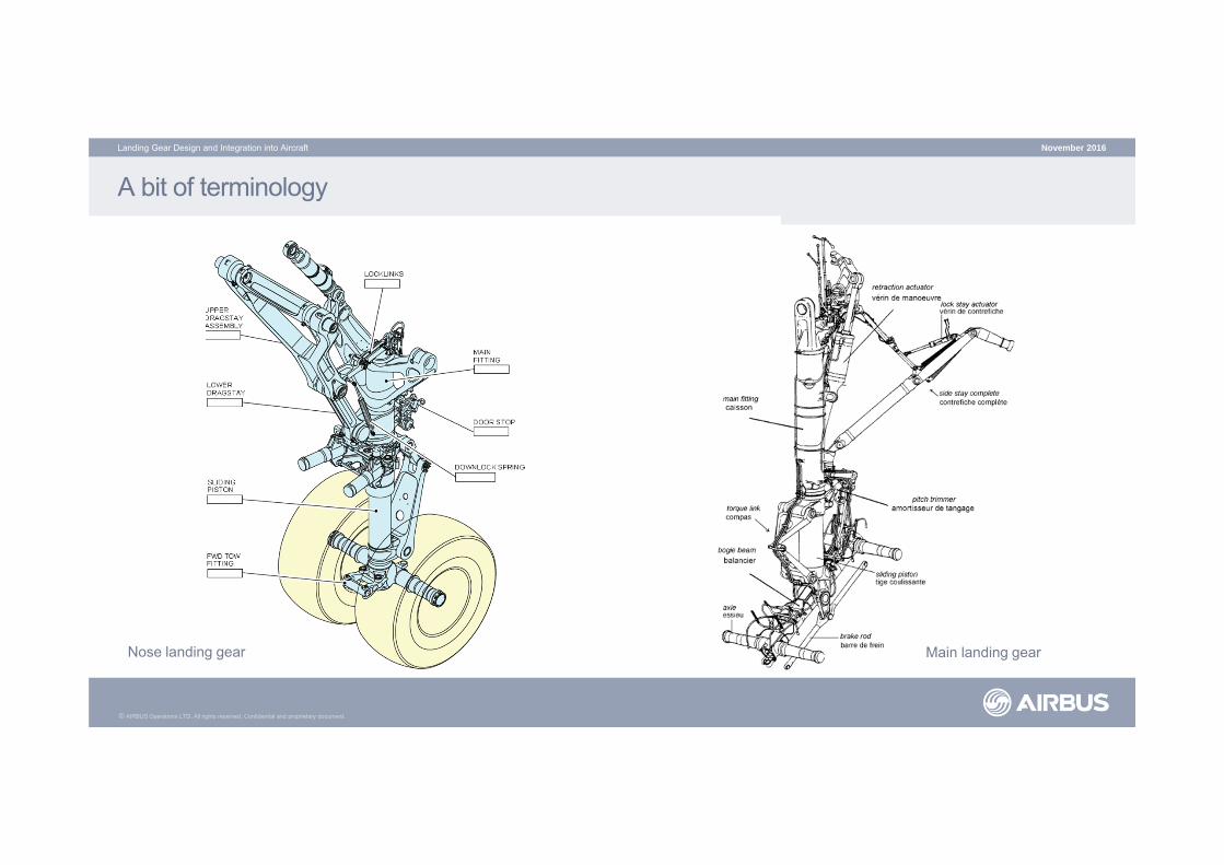
At a later stage, the dynamic FEM of the gear becomes available, and it is then integrated into the AC Dynamic Master Module (DMM)
This allows a full load loop to be calculated, this time fully taking into account
• AC flexibility
• LG flexibility
• Tyres behaviour
• SA characteristics
• AC control logic
Ground loads so generated are then used to fine tune the AC and LG design
MLG beam modelA/C dynamic model with LGs embedded
A/C dynamic model with LGs embedded

© AIRBUS Operations LTD. All rights reserved. Confidential and proprietary document.
Do LGs size the aircraft?
November 2016Landing Gear Design and Integration into Aircraft
Dynamic landingTaxi
Landing braked rollTowing
Dynamic brakingTaxi
Steering
Dynamic landingTaxi
Loads can be controlled using:
• Spring/damping curve
• LG geometry
• Unsprung mass
• Brake logic
• Lift dump logic
• Gear/Aircraft stiffness
Fuselage/wing sizing cases influenced by LG
© AIRBUS Operations LTD. All rights reserved. Confidential and proprietary document.
LG stability
November 2016Landing Gear Design and Integration into Aircraft
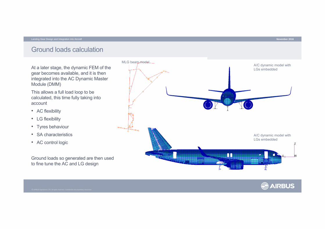
The dynamic LG models are also used to analyse the stability of the LG while steering, or when excited by Out Of Balance loads, and shimmy
Out of balance accelerations spectrogram Video: Hawker Siddeley 125 NLG shimmy

© AIRBUS Operations LTD. All rights reserved. Confidential and proprietary document.
Resources
Videos:
• MD80 hard landing: https://youtu.be/C74ZXW2NlSY
• Ground loop: https://youtu.be/Dz2_QJpfqXI
• Airbus YouTube channel: https://www.youtube.com/user/airbus
Further readings:
Norman S. Currey, Aircraft Landing Gear Design: Principles and Practices (AIAA Education)
November 2016Landing Gear Design and Integration into Aircraft

© AIRBUS Operations LTD. All rights reserved. Confidential and proprietary document.
November 2016Landing Gear Design and Integration into Aircraft
© AIRBUS Operations LTD. All rights reserved. Confidential and proprietary document. This document and all information contained herein is the sole property of AIRBUS Operations LTD. No intellectual property rights are granted by the delivery of this document orthe disclosure of its content. This document shall not be reproduced or disclosed to a third party without the express written consent of AIRBUS Operations LTD. This document and its content shall not be used for any purpose other than that for which it is supplied.The statements made herein do not constitute an offer. They are based on the mentioned assumptions and are expressed in good faith. Where the supporting grounds for these statements are not shown, AIRBUS Operations LTD. will be pleased to explain thebasis thereof. AIRBUS, its logo, A300, A310, A318, A319, A320, A321, A330, A340, A350, A380, A400M are registered trademarks.