Leica TPS400 Series User Manual
162
Leica TPS400 Series User Manual Version 5.0 English
Transcript of Leica TPS400 Series User Manual

Leica TPS400 SeriesUser Manual
VersionEnglish
5.0

used in this manual used in this User Manual have the anings:
GERates an imminently hazardous situation avoided, will result in death or serious
NINGates a potentially hazardous situation ded use which, if not avoided, could
th or serious injury.
TIONates a potentially hazardous situation ded use which, if not avoided, may r or moderate injury and / or appre-
ial, financial and environmental
rtant paragraphs which must be practice as they enable the product to
technically correct and efficient manner.
2TPS400-5.0.1en
Electronical Total StationCongratulations on your purchase of a new Leica Geosystems Total Station.
This manual contains important safety directions as well as instructions for setting up the product and operating it. Refer to "Safety Directions" for further information.Read carefully through the User Manual before you switch on the product.
Product identificationThe model and the serial number of your product is indicated on the type plate.Enter the model and the serial number in your manual and always refer to this information when you need to contact your agency or Leica Geosys-tems authorized service workshop.
Type: ____________ Serial no.: ____________
Symbols The symbolsfollowing me
� DANIndic
which, if not injury.
� WARIndic
or an unintenresult in dea
� CAUIndic
or an unintenresult in minociable materdamage.
Impoadhered to inbe used in a

TPS400-5.0.1en
3Trademarks• Windows is a registered trademark of Microsoft
CorporationAll other trademarks are the property of their respec-tive owners.

. Where there are differences between
M mode "IR" this telescope type uses axially from the telescope's objective.
s EDM additionally offer the EDM EDM modes a narrow visible red laser
4TPS400-5.0.1en
Validity of this manualDescription
General This manual applies to all TPS400 Series instrumentsthe various models they are clearly described.
Telescope • When measuring distances to a reflector with EDa wide visible red laser beam, which emerges co
• Instruments that are equipped with a reflectorlesmodes "RL" and "RL-Prism". When using these beam is used to measure distances.

TPS400-5.0.1en
..................................... 113rotection with PIN ..... 114rage............................ 115
tions ............................ 122ta ................................ 143 Limited Warranty, ense Agreement ........ 153..................................... 155
5Contents - Overview
Contents - OverviewContents - Overview........................... 5Contents.............................................. 6Introduction ........................................ 9Operating the product...................... 18Measuring Preparation / Setting up 26FNC Key ............................................ 43Programs........................................... 50Settings ............................................. 93EDM Settings .................................... 98File Management ............................ 103Start-up sequence .......................... 106Calibrations..................................... 107COMM Parameters ......................... 111Data Transfer .................................. 112
System InfoInstrument PCare and StoSafety DirecTechnical DaInternationalSoftware LicIndex ...........

Contents
........................................................ 25
g Preparation / Setting up .. 26....................................................... 26
Replacing Battery ....................... 27ower supply for total ......................................................... 29 the tripod...................................... 30t Setup........................................... 31up with the electronic levelep ................................................... 33nsity................................................ 34ositioning ...................................... 34e - method 1 ................................. 35e - method 2 ................................. 35........................................................ 36haracters ......................................... 36characters........................................ 37l and Alphanumerical input......... 38ch .................................................... 40earch............................................. 41....................................................... 42
6TPS400-5.0.1en
ContentsIntroduction .................................................... 9
Special features............................................. 10Important parts............................................... 11Technical terms and abbreviations ............ 12Area of applicability....................................... 15PC Program Package Leica Geo Office Tools (LGO-Tools) ......... 15
Installation on the PC ..................................... 15Program content............................................. 15
Power Supply................................................. 17
Operating the product ............................. 18Keypad ............................................................ 18
Fixed keys ...................................................... 19Trigger key...................................................... 19Selection of Language.................................. 19Distance measurement ................................ 20Softkeys .......................................................... 23Symbols .......................................................... 24
Status symbol "EDM type" ............................. 24Status symbol "Battery capacity" ................... 24Status symbol "Compensator" ....................... 24Status symbol "Offset" ................................... 24
Menu treeMeasurin
UnpackingInserting /External pstation.....Setting upInstrumenLevelling step-by-stLaser inteHints for pInput modInput modEdit mode
Erasing cInserting
NumericaPointsearWildcard sMeasuring

TPS400-5.0.1en
.................................................. 80nal) ............................................ 82ane (optional) ............................ 88.................................................. 91
.................................................. 93
s ............................................... 98
ent...................................... 103
uence ................................... 106
................................................ 107error (Hz-collimation)........... 108ical index error) .................... 108
eters .................................. 111
r ............................................. 112
................................................ 113
rotection with PIN......... 114
rage ..................................... 115................................................ 115................................................ 115............................................... 116
7Contents
FNC Key.......................................................... 43Light On /Off................................................... 43Level/Plummet ............................................... 43IR/ RL Toggle................................................. 43Laser Pointer.................................................. 43Free-Coding ................................................... 43Units................................................................. 43Delete Last Record ....................................... 44Lock with PIN ................................................. 44Target Offset .................................................. 44Height Transfer.............................................. 47Hidden Point................................................... 48
Programs ....................................................... 50Application pre-settings................................ 50
Setting job ...................................................... 50Setting Station................................................ 51Orientation...................................................... 52
Applications.................................................... 56Introduction .................................................... 56Surveying ....................................................... 57Stake out ........................................................ 58Free Station.................................................... 60Reference Line............................................... 67Tie Distance ................................................... 73Area & Volume ............................................... 76Remote Height ............................................... 79
Construction .COGO (optioReference Pl
Coding...........
Settings.........
EDM SettingFile ManagemStart-up seqCalibrations
Line-of-sight V-Index (Vert
COMM ParamData TransfeSystem Info.
Instrument PCare and Sto
Transport ......In the field.....Inside vehicle

Contents
Data........................................... 143ric correction .............................. 149 formulae ...................................... 151
nal Limited Warranty, License Agreement............. 153al Limited Warranty.................. 153
License Agreement.................... 153
....................................................... 155
8TPS400-5.0.1en
Shipping ....................................................... 116Storage.......................................................... 116
Batteries ....................................................... 117Cleaning ....................................................... 118
Checking and adjusting.............................. 119Tripod ........................................................... 119Circular level ................................................ 119Circular level on the tribrach ........................ 120Laser plummet ............................................. 120
Safety Directions...................................... 122Intended Use................................................ 122
Permitted use ............................................... 122Adverse use ................................................. 122
Limits of Use ................................................ 123Responsibilities............................................ 124Hazards of Use............................................ 125Laser classification...................................... 129
General ........................................................ 129Distancer, Measurements with Reflectors (IR mode) ..................................................... 129Distancer, Measurements without Reflectors (RL mode) .................................................... 132Electronic Guide Light EGL.......................... 136Laser plummet ............................................. 137
Electromagnetic Compatibility EMC ........ 139FCC Statement (Applicable in U.S.) ........ 141
TechnicalAtmosphe
Reduction
InternatioSoftware
InternationSoftware
Index........

TPS400-5.0.1en
9IntroductionIntroductionThe Leica Geosystems TPS400 is a high-quality electronic total station.Its innovative technology makes the daily surveying jobs easier.The instrument is ideally suited for simple construc-tion surveys and setting out tasks.The easy operation of the instrument functions can be learned without problems in no time.

Introduction
10TPS400-5.0.1enSpecial features• Easy and quickly to learn !• Interactive keys; with large and clear LCD.• Small, light-weight and easy-to-use.• Measurements without reflector with the inte-
grated visible laser beam (TCR instruments).• Additional trigger key on side cover.• Continuous drives for horizontal and vertical
angles (tangent screws).• With laser plummet as standard.

TPS400-5.0.1en
ide light EGL (optional)
for GEB111rcussing graticulelescope imagearrying handle with mounting
ce RS232
h integrated Electronic Distance t (EDM); Beam exit
l
ive
11Introduction
Important parts1) Optical sight2) Integrated gu3) Vertical drive4) Battery5) Battery stand6) Battery cove7) Eyepiece; fo8) Focussing te9) Detachable c
screws10) Serial interfa11) Foot screw12) Objective wit
Measuremen13) Display14) Keyboard15) Circular leve16) On/Off key17) Trigger key18) Horizontal drInstrument with EGL Instrument without EGL

Introduction
sight / collimation axisis = line from the reticle to the centre of .ng axision axis of the telescope. axistation axis of the telescope (Trunion
angle / zenith anglel circleircular division for reading the V-angle.
ntal directionntal circleircular division for reading the Hz-
12TPS400-5.0.1en
Technical terms and abbreviations
ZA = Line ofTelescope axthe objectiveSA = StandiVertical rotatKA = TiltingHorizontal roaxis).V = Vertical VK = VerticaWith coded cHz = HorizoHK = HorizoWith coded cangle.

TPS400-5.0.1en
lumb line / Compensatorirection of gravity. The compen-ator defines the plumb line within he instrument.
enithoint on the plumb line above the bserver.
eticlelass plate within the telescope ith reticle.
13Introduction
Standing axis inclinationAngle between plumb line and standing axis. Standing axis tilt is not an instrument error and is not eliminated by measuring in both faces. Any possible influence it may have on the Hz-direction resp. V-angle is eliminate by the dual axis compensator.Line-of-sight error (Hz-collima-tion)The line-of-sight error is the devia-tion from the perpendicular between tilting axis and line-of-sight. This could be eliminated by measuring in both faces.V-Index (Vertical index error)With horizontal line-of-sight the V-circle reading should be exactly 90°(100gon). The deviation from this values is termed V-index (i).
PDst
ZPo
RGw

Introduction
ated meteorological corrected slope nce between instrument tilting axis and re of prism/laser spot (TCR).ated meteorological corrected hori-al distance.ht difference between station and t point.ctor height above ground
ument height above groundon coordinate (Easting)on coordinate (Northing)on heighting of target pointhing of target pointht of target point
14TPS400-5.0.1en
IndicdistacentIndiczontHeigtarge
hr Reflehi InstrE0 StatiN0 StatiH0 StatiE EastN NortH Heig

TPS400-5.0.1en
n call program "setup.exe" in the ools on the CD-ROM and follow ions of the installation program.
ntinstallation the following programs
ge Manager hange of coordinates, measure-lists and output formats between nd PC.Editort as well as creating and f coordinate files.nager and processing of codelists.load ystem software and EDM-software. Software upload only LGO/LGO-ersion 3.0 or higher must be used ration.
15Introduction
Area of applicabilityThis User Manual is valid for all instruments of the TPS400 Series.
PC Program Package Leica Geo Office Tools (LGO-Tools)The program package LGO-Tools is used for the data exchange between the Total Station and the PC. It contains several auxiliary programs in order to support your use of the instrument.
Installation on the PCThe installation program can be found on the CD-ROM supplied. Please note that LGO-Tools can only be installed on computers with MS Windows 2000, XP and Vista operating systems.
Any previous versions of LGO-Tools on your computer must be uninstalled first before installing the new version.
For the installatiodirectory \LGO-Tthe input instruct
Program conteAfter successful appear:
Tools• Data Exchan
For data excments, codeinstrument a
• Coordinate Import/Exporprocessing o
• Codelist MaFor creating
• Software UpFor loading s
For EDMTools Software Vfor error free ope

Introduction
16TPS400-5.0.1enNot using the correct upload Software can permanently damage the instrument.
Before the Software Upload, always insert a charged battery into the instrument.• Format Manager
For creating of own, special formatted data output files.
• Configuration Manager Import/Export as well as creating of instrument configuration.
For more information about LGO-Tools refer to the comprehensive Online Help.

TPS400-5.0.1en
n the battery adapter GAD39
ystems instrument is powered by g-in batteries. For this product, we basic battery (GEB111) or the Pro ). Optionally six single cells can be D39 battery adapter. tteries (1.5 V each) supply 9 Volts. the instrument is designed for a (GEB111/ GEB121). ry charge is not displayed correctly
e cells. Use the single cells with the s emergency power supply. The single cells is in a lower rate of ver long periods.
17Introduction
Power SupplyUse the Leica Geosystems batteries, chargers and accessories or accessories recommended by Leica Geosystems to ensure the correct functionality of the instrument.Power for the instrument can be supplied either internally or externally. An external battery is connected to the instrument using a LEMO cable.• Internal battery:
One GEB111 or 121 battery fit in the battery compartment.
• External battery:One GEB171 battery connected via cable.
1 GEB1212 GEB1113 Single cells i
Your Leica Geosrechargeable plurecommend the battery (GEB121used with the GASix single cell baThe voltmeter onvoltage of 6 Volts
The battewhen using singlbattery adapter aadvantage of thedischarge even o

Operating the Instrument
measured field.
ysh firmly assigned functions.n keysf input bar in edit and input mode or f focus bar. keysned the variable functions displayed at m of the screen.ar
functions that can be called up with the keys.
18TPS400-5.0.1en
Operating the InstrumentThe On / Off key is located on the side cover of the TPS400.
All shown displays are examples. It is possible that local software versions are different to the basic version.
Keypad
1) FocusActively
2) Symbols3) Fixed ke
Keys wit4) Navigatio
Control ocontrol o
5) FunctionAre assigthe botto
6) Softkey bDisplaysfunction

TPS400-5.0.1en
nt trigger has three settings (ALL,
ctivated in the configuration menu.
Languagen the instrument the user is able to rred language.ose the language is only shown if
re loaded onto the instrument and n is set in Settings dialog. onal language connect the instru-ls Version 4.0 or higher via the
nd load using "LGO Tools - Soft-
19Operating the Instrument
Fixed keys[PAGE] Scrolls to next page when a dialogue
consists of several pages.[MENU] Accesses programs, settings, the data
manager, adjustments, communica-tions parameters, system information and data transfer.
[USER] Key, programmable with function from the FNC menu.
[FNC] Quick-access to measurement-supporting functions.
[ESC] Quit a dialog or the edit mode with acti-vation of the "previous" value. Return to next higher level.Confirm an input; continue to the next field.
Trigger keyThe measuremeDIST, OFF).The key can be a
Selection ofAfter switching ochoose his prefeThe dialog to chotwo languages aLang.choice: OTo load an additiment to LGO Tooserial interface aware Upload".

Operating the Instrument
, cars, animals, swaying branches, etc. er beam while a measurement is being tion of the laser beam is reflected and incorrect distance values.pting the measuring beam while taking measurements or measurements using s. Measurements to prism reflectors are an object crosses the measuring beam of 0 to 30m and the distance to be more than 300m.ecause the measuring time is very er can always find a way of avoiding situations. short distances may be measured in IR mode to well reflecting targets. distances are corrected with the addi- defined for the active reflector.
20TPS400-5.0.1en
Distance measurementA laser distancer (EDM) is incorporated into the instruments of the TPS400 series.In all versions, the distance can be determined by using a laser beam which emerges coaxially from the telescope objective.
Measurements to strongly reflecting targets such as to traffic lights in Reflector EDM mode without prism should be avoided. The measured distances may be wrong or inaccu-rate.For applications without reflector, a special arrange-ment of the EDM, and appropriate arrangement of the beam paths, enable ranges of over five kilome-tres to be attained with standard prisms. Miniprisms, 360° reflectors and reflector tapes can also be used, and measurement is also possible without a reflector.
When a distance measurement is trig-gered, the EDM measures to the object which is in the beam path at that moment.
If e.g. peoplecross the lastaken, a fracmay lead to Avoid interrureflectorless reflective foilonly critical ifat a distancemeasured isIn practice, bshort, the usthese critical
Veryreflectorless Note that thetive constant

TPS400-5.0.1en
that the laser beam is not reflected to the line of sight (e.g. highly ).istance measurement is triggered, es to the object which is in the t moment. In case of temporary
a passing vehicle, heavy rain, fog M may measure to the obstruction.easuring longer distances, any red laser beam from the line of
to less accurate measurements. the laser beam might not be e point at which the crosshairs are
commended to verify that the R-ated with the telescope line of
chapter "Checking and adjusting").easure with two instruments to the ltaneously.
21Operating the Instrument
Incorrect result
Correct result
ReflectorlessBe sure
by anything closereflective objects
When a dthe EDM measurbeam path at thaobstruction (e.g.or snow) the ED
When mdivergence of thesight might lead This is because reflected from thpointing.Therefore, it is relaser is well collimsight (refer to the
Do not msame target simu

Operating the Instrument
22TPS400-5.0.1enRed laser to prismsAccurate measurements to prisms should
be made with the standard program (Reflector EDM mode).Red laser to reflector tapeThe visible red laser beam can be used to measure to reflective foils, also. To guarantee the accuracy the red laser beam must be perpendicular to the reflector tape and it must be well adjusted (refer to the chapter "Checking and adjusting").
Make sure the additive constant belongs to the selected target (reflector).

TPS400-5.0.1en
s:s distance and angle measure-ts and saves measured values.s distance and angle measure-ts without saving measured values.s displayed values.tes current value in the display and ady for the input of a new value.ns the coordinate input mode.lays the list of available points.s the search for the point entered.lays EDM settings.les between reflector and reflector-measurement modes. to last active dialog.inue to next dialog.rns to highest softkey level.ext softkey level.isplayed message or dialog and
dialog.her information about menu/appli-ttons in the relevant sections.
23Operating the Instrument
Softkeys
Under softkeys, a selection of commands and func-tions is listed at the bottom of the screen. They can be activated with the corresponding function keys. The available scope of each function depends on the applications / functions currently active.
General softkey[ALL] Start
men[DIST] Start
men[REC] Save[ENTER] Dele
is re[ENH] Ope[LIST] Disp[FIND] Start[EDM] Disp[IR/RL] Togg
less [PREV] Back[NEXT] Cont
RetuTo n
[OK] Set dquit
Find furtcation specific bu

Operating the Instrument
bol "EDM type"eflector EDM mode for measuring to risms and reflective targets.eflectorless EDM for measuring to all
argets.
bol "Battery capacity"he battery symbol indicates the level of
he remaining battery capacity (75% full hown in the example).
bol "Compensator"ompensator is on.
ompensator is off.
bol "Offset"ffset is active.
24TPS400-5.0.1en
SymbolsDepending on software version different symbols are displayed indicating a particular operating status.
A double arrow indicates choice fields.
Using the navigation keys the desired parameter can be selected. Quits a selection with the enter key or the navigation keys.
Indicates that several pages are avail-able which can be selected with [PAGE].
Indicates telescope position I or II.
Indicates that Hz is set to "left side angle measurement" (anti-clockwise).
Status symRpRt
Status symTts
Status symC
C
Status sym! O

TPS400-5.0.1en
—— File Management —— Job —— Fixpoints —— Measurements —— Codes —— Initialize Memory —— Memory Statisticenu —— Calibrations —— Hz-Collimation —— V-Index —— View Calibration Data—— Communication Parameters —— Baudrate —— Databits —— Parity —— Endmark —— Stopbits—— Data Transfer —— Job —— Data —— Format—— System Info —— Battery —— Instrument temperature —— Date —— Time—— Start-up sequence
—— PIN Protection
25Operating the Instrument
Menu tree[MENU] > Confirm menu selection.[PAGE] Scroll to next page.
Depending on user interface sequence and arrangement of menu items may be different.
-
—— Programs —— Surveying —— Setting out —— Free Station —— Reference line —— Tie Distance —— Area & Volume
—— Remote Height
——————
ConstructionCOGOReference Plane
——
Settings
—— Contrast, Trigger Key, USER key, V-Setting,
Tilt Correction —— Sector Beep, Beep, Hz Incrementation, Reticle Illumin., DSP Heater —— Data Output, GSI 8/16, Mask 1/2/3 Hz Collimation, Auto-Off, Language —— Min. Reading, Angle Unit, Distance Unit, Distance Decimals Temperature, Pressure —— EDM Settings —— EDM-Mode
—— Prism Type—— Prism Constant—— Laser Pointer—— Guide Light
Menu
M

Measuring Preparation /Setting up
le (optional)epiece or eyepiece for steep angles )tionble tribrach (optional)harger and accessories (optional)nt toolsEB111 (optional)
Mini prism adapter (optional)EB121 (optional)
ini prism (optional)bracket GHT196 for height meter )eter GHM007 (optional)e cover / Lens hoodm rodsm + holder (optional)nualeight for Zenith eyepiece (optional)
26TPS400-5.0.1en
Measuring Preparation / Setting up
UnpackingRemove TPS400 from transport case and check for completeness:
1) Data cab2) Zenith ey
(optional3) Total sta4) Remova5) Battery c6) Adjustme7) Battery G8) GAD1059) Battery G10) Tip for m11) Spacing
(optional12) Height m13) Protectiv14) Mini pris15) Mini pris16) User Ma17) Counterw
1
34
2
5
6
7
89
10
11
12
13
15
14
16
17

TPS400-5.0.1en
ery.
into battery holder.
holder into the instrument.
ttery correctly (note pole markings e battery holder). Check and insert e to side into the housing.
e battery refer to chapter "Charging ".of battery refer to chapter "Tech-
27Measuring Preparation / Setting up
Inserting / Replacing Battery
1. Remove battery holder.
2. Remove batt
3. Insert battery
4. Insert battery
Insert baon the inside of thbattery holder tru• To charge th
the batteries• For the type
nical data".

Measuring Preparation /Setting up
ration/Dischargingbatteries can be operated from -20°C to o +131°F.g temperatures reduce the capacity rawn; very high operating temperatures ervice life of the battery.
28TPS400-5.0.1en
When using the GEB121 battery, remove the spacer for the GEB111 from the battery compartment.
Charging / first-time use• The battery must be charged prior to using for
the first time because it is delivered with an energy content as low as possible.
• For new batteries or batteries that have been stored for a long time (> three months), it is effectual to make 3 - 5 charge/discharge cycles.
• The permissible temperature range for charging is between 0°C to +35°C / +32°F to +95°F. For optimal charging we recommend charging the batteries at a low ambient temperature of +10°C to +20°C/+50°F to +68°F if possible.
• It is normal for the battery to become warm during charging. Using the chargers recom-mended by Leica Geosystems, it is not possible to charge the battery if the temperature is too high.
OpeThe
+55°C/-4°F tLow operatinthat can be dreduce the s

TPS400-5.0.1en
pen up one ferrite core and clip it ly cable, about 2cm away from the e using the supply cable for the first h a TPS400 instrument.
29Measuring Preparation / Setting up
External power supply for total stationTo meet the conditions stipulated for electromag-netic acceptability when powering the TPS400 from an external source, the supply cable used must be equipped with a ferrite core.
The Lemo plug with the ferrite core always has to be attached at the instrument side.
The cables supplied along with your instrument include a ferrite core as standard. If you are using older cables without ferrite core, it's necessary to attach ferrite cores to the cable.If you need additional ferrite cores, please contact your local Leica Geosystems agency. The spare-part number of the ferrite core is 703 707.
For assembling oaround the suppLemo plug, befortime together wit

Measuring Preparation /Setting up
he clamping screws on the tripod legs, o the required length and tighten the
to guarantee a firm foothold sufficiently tripod legs into the ground. When
the legs into the ground note that the st be applied along the legs.
n setting up the tripod pay attention to a sition of the tripod plate. tions of inclination can be made with the f the tribrach. Larger corrections must the tripod legs.n using a tribrach with an optical laser plummet cannot be used.
30TPS400-5.0.1en
Setting up the tripod 1. Loosen tpull out tclamps.
2. In order press thepressingforce mu
Whehorizontal poSlight correcfoot screws obe done with
Wheplummet, the

TPS400-5.0.1en
etup
bes an instrument setup over a oint using the laser plummet. It is
to set up the instrument without the d ground point.
t features:ys recommended to shield the nt from direct sunlight and avoid emperatures around the instru-
r plummet described in this topic is the vertical axis of the instrument. s a red spot onto the ground, t appreciably easier to centre the nt.r plummet cannot be used in ion with a tribrach equipped with an lummet.
31Measuring Preparation / Setting up
Careful handling of tripod• Check all screws and bolts for correct fit.• During transport always use the cover supplied.• Use the tripod only for surveying tasks.
Instrument SDescriptionThis topic descrimarked ground palways possible need for a marke
Importan• It is alwa
instrumeuneven tment.
• The lasebuilt intoIt projectmaking iinstrume
• The laseconjunctoptical p

Measuring Preparation /Setting up
the instrument and switch on the laser and electronic level by pressing [FNC] Plummet]. tripod legs (1) and use the tribrach s (6) to centre the plummet (4) over
nd point.e tripod legs to level the circular level
the electronic level turn the tribrach s (6) to precisely level the instrument.efer to "Levelling up with the electronic
p-by-step" for more information.e instrument precisely over the ground
by shifting the tribrach on the tripod .teps 6. and 7. until the required accu-chieved.
32TPS400-5.0.1en
Setup step-by-step
1. Extend the tripod legs to allow for a comfortable working posture. Position the tripod over the marked ground point, centring it as well as possible.
2. Fasten the tribrach and instrument onto the tripod.
3. Turn on plummet> [Level/
4. Move thefootscrewthe grou
5. Adjust th(7).
6. By usingfootscrew
Rlevel ste
7. Centre thpoint (4)plate (2)
8. Repeat sracy is a
2
6
7
5 4
5
51
3
1
1

TPS400-5.0.1en
ootscrews. When the electronic ed the arrows are replaced by
lec-r the
by st
n the
otscrew. When the electronic level arrow is replaced by a checkmark.
n the el is three are stru-
en led
OK].
33Measuring Preparation / Setting up
Levelling up with the electronic level step-by-stepThe electronic level can be used to precisely level up the instrument using the footscrews of the tribrach.1. Turn on the instrument and switch on the elec-
tronic level by pressing [FNC] > [Level/Plummet].
2. Centre the circular level approximately by turning the footscrews of the tribrach.
The bubble of the electronic level and the arrows for the rotating direction of the foot-screws only appear if the instrument tilt is inside a certain levelling range.
3. Turn the instrument until it is parallel to two foot-screws.
4. Centre the elec-tronic level of this axis by turning the two footscrews. Arrows show the direction for
rotating the flevel is centrcheckmarks.
5. Centre the etronic level fosecond axis turning the lafootscrew. Aarrow showsdirection for rotating the fois centred the
Wheelectronic levcentred and checkmarks shown, the inment has beperfectly leveup.
6. Accept with [

Measuring Preparation /Setting up
positioning
over pipes or depressions circumstances the laser spot is not ver pipes). In this case, the laser spot visible by using a transparent plate so spot can be easily aligned to the centre
34TPS400-5.0.1en
Laser intensityChanging the laser intensityExternal influences and the surface conditions may require the adjustment of the intensity of the laser. The laser can be adjusted in 25% steps as required.
Hints for
PositioningUnder somevisible (e.g. ocan be madethat the laserof the pipe.

TPS400-5.0.1en
method 2nter text or numeric values.
he full range of available charac-rs are displayed on the screen.election of range of characters/ nge of numbers.ps 3 and 4 from method 1.od you like to use can be set in the
PtId:
*ABC DEFG HIJK LMNO
F1 F2 F3 F4
+ - LMNO .$ !
35Measuring Preparation / Setting up
Input mode - method 1In entry mode, enter text or numeric values.
[INPUT] 1. Delete entry, display numeric/ alpha-numeric softkey bar. The cursor indi-cates that the instrument is ready for input.
2. Selection of range of characters/ range of numbers.
[>>>] Additional characters/ numbers.3. Select the desired character. Char-
acter shifts to the left.4. Confirm entry.
[ESC] Deletes input and restores previous value.
Input mode -In entry mode, e
[INPUT] 1. Tte
2. Sra
Proceed with steThe meth
settings.
-
-
PtId:
F1 1234 5678 90. F2 *ABC DEFG HIJKF3 PQRS TUVW XYZ_F4 &?#@ %*/
-

Measuring Preparation /Setting up
racters1. Place cursor on character to be
deleted.2. Pressing the navigation key deletes
the relevant character.3. Confirm input.
Deletes the change and restores the previous value.
36TPS400-5.0.1en
Edit modeExisting characters are changed in the edit mode.
1. Start edit mode. Vertical edit bar is positioned flush right.Edit bar is positioned flush left.
2. Select range of characters/ range of numbers.
[>>>] Additional characters / numbers.
3. Overwrite existing characters.
4. Confirm input.
[ESC] Deletes change and restores previous value.
Erasing cha
[ESC]
Info4: PREP Info4: PROP
-
-

TPS400-5.0.1en
37Measuring Preparation / Setting upInserting charactersIf a character was skipped (e.g. -15 instead of -125) you can insert it later.
1. Place cursor on "1".
2. Inserts an empty character on the right of "1".
3. Select range of characters /range of numbers.
4. Select relevant character.
5. Confirm input.
-
-

Measuring Preparation /Setting up
put
rical input
38TPS400-5.0.1en
Numerical and Alphanumerical inputInput is made with the softkey bar and the assigned function keys.Position the marker in the relevant field.[INPUT] 1. Calls up the input dialogue.
2. Select range of characters /range of numbers.
[>>>] Additional characters / numbers.
3. Confirm input.
Selection is limited to valid digits for entries, that due to their display characteristics, fall into a certain range (e.g. angles in degrees).
Numerical in
Alphanume
-

TPS400-5.0.1en
try "*" can be used in data fields bers or codes can be searched for.
umeric character set "+" and "-" are rmal alphanumeric characters with tical function.acters during Wildcard point search (see card search"). ppears only in the front position of
it mode the position of the decimal changed. The decimal place is
39Measuring Preparation / Setting up
Character setEntry mode contains the following characters for numeric and alphanumeric input.
The character enwhere point numSigns+/- In the alphan
treated as nono mathema
Additional char* Place holder
chapter "Wild"+" / "-" a
an input.In the ed
place cannot be skipped.
Numerical Alphanumerical" + " " - "" . "" 0 - 9 "
(ASCII 43) (ASCII 45) (ASCII 46) (ASCII 48 - 57)
" "" ! "" # "" $ "" % "" & "" ( "" ) "" * "" + "" , "" - "" . "" / " " : "" < "" = "" > "" ? "" @ "" A - Z"" _ "
" ‘ "
(ASCII 32) [space] (ASCII 33) (ASCII 35) (ASCII 36) (ASCII 37) (ASCII 38)(ASCII 40)(ASCII 41) (ASCII 42) (ASCII 43) (ASCII 44) (ASCII 45) (ASCII 46) (ASCII 47)(ASCII 58)(ASCII 60)(ASCII 61)(ASCII 62) (ASCII 63) (ASCII 64) (ASCII 65 .. 90)(ASCII 95) [Underscore](ASCII 96)

Measuring Preparation /Setting up
Displays the coordinates and the job of the selected point.For manual input of coordinates.Confirm selected point.To select a different job.
40TPS400-5.0.1en
PointsearchPointsearch is a global function used by applications to e.g. find internally saved measured or fixed points.It is possible for the user to limit the point search to a particular job or to search the whole storage.The search procedure always finds fixed points before measured points that fulfill the same search criteria. If several points meet the search criteria, then the points are listed according to their age. The instrument finds the most current (youngest) fixed point first.Direct searchBy entering an actual point number (e.g. "P13") all points with the corresponding point number are found.
[VIEW]
[ENH][OK][JOB]

TPS400-5.0.1en
ny length with a "1" as the second found (e.g.: A1, B12, A1C).
any length with an "A" as the first d a "1" as the third character are AB1, AA100, AS15).
41Measuring Preparation / Setting up
Wildcard searchThe Wildcard search is indicated by a "*". The asterisk is a place holder for any following sequence of characters.Wildcards are always used if the point number is not fully known, or if a batch of points is to be searched for.
Starts point search.Examples:* All points of any length are found.A All points with exactly the point number "A" are
found.A* All points of any length starting with "A" are
found (e.g.: A9, A15, ABCD).
*1 All points of acharacter are
A*1 All points of character anfound. (e.g.:

Measuring Preparation /Setting up
a possible measuring display:
Calling up the assigned function.
42TPS400-5.0.1en
MeasuringAfter switching on and setting up correctly, the total station is immediately ready for measuring.In the measurement display it is possible to call up fixed keys and function keys, as well as trigger keys and their functions
All shown displays are examples. It is possible that local software versions are different to the basic version.
Example of
-

TPS400-5.0.1en
asurements with prisms.asurements without prisms.ation in chapter "EDM Settings".
rff the visible laser beam for illumi- point. The new settings are ut one second and then saved.
o select a code from a codelist or . Some functionality like softkey
ent distance and angle unit and lity to change these.
43FNC Key
FNC KeyUnder [FNC] several functions can be called up. Their applications are described below.
Functions can also be started directly from the different applications.
Each function from the FNC menu can be assigned to the [USER]-key (see chapter "Settings").
Light On /OffSwitches display light on / off.
Level/PlummetThis function enables the electronic bubble and the range of intensity settings of the laser plummet.
IR/ RL ToggleChange between the two EDM types IR (on Reflec-tors) and RL (Reflectorless). New setting is displayed for about one second.
IR: Distance meRL: Distance meFind more inform
Laser PointeSwitches on or onating the targetdisplayed for abo
Free-CodingStarts "Coding" tenter a new codebutton [CODE].
UnitsDisplays the currgives the possibi

FNC Key
fsetsible to set up the reflector directly, or
ible to aim the target point directly, the (length, cross and/or height offset) can he values for the angle and distances
d directly for the target point.
ffset point is higher than measurement
Measure-ment Pt.
Offset Pt.
L_O
ffset
+
T_Offset +
T_Offset -
fset -
44TPS400-5.0.1en
Delete Last RecordThis function deletes the last recorded data block. This can be either a measurement block or a code block.
Deleting the last record is not reversible!Only records can be deleted which were
recorded in "Surveying" or in "Measuring".
Lock with PINThis function is used to prevent unauthorized use of the instrument. It enables you to lock the instru-ment from any application by pressing [FNC] > [Lock with PIN] without switching off the instrument. After that the instrument will prompt for a PIN code entry.
The function is available when the PIN protection is activated under [MENU] > [PIN].
Target OfIf it is not posit is not possoffset valuesbe entered. Tare calculate
H_Offset +: O
L_Of

TPS400-5.0.1en
surement has been triggered or
plicability can be set as follows:
t values are always reset to 0 when quit.
subapplication to determine the coordinates of the lindrical objects and their radius.
izontal angle to a point on the left side of the object as well as the bject.
The offset values are reset to 0 after the point is saved.
The offset values are applied to all further measurements.
45FNC Key
Procedure:1. Enter the offset values (length, cross and/or
height) as per the sketch.2. Define the period for which the offset is to be
applied.[RESET]: Sets eccentricity to zero.
3. [SET]: calculates the corrected values and jumps to the application from which the offset function was started. The corrected angle and distances are displayed as soon as a valid
distance meaexists.
The period of ap
The offsethe application is
Cylinder Offset Use [CYLNDER]centre point of cyMeasure the horand on the right distance to the o
RESET CYLNDER OK
Trav. Offset: 0.600 mLength Offset: 0.800 mHeight Offset: 0.500 mMode : Reset after REC
Enter offset values!
Reset after REC
Permanent

FNC Key
prism offset. This is the distance the centre of the prism and the surface ject to be measured. If the EDM mode e value is set to zero automatically.vertical hair, aim at the left side of the en press [HzLeft].
vertical hair, aim at the right side of the en press [HzRight].e instrument accordingly such that the deviation angle, is zero.
HzRight ALL EXIT
YLINDRICAL OFFSET : 120.4361 g : 141.4435 g : 99.4658 g : 15.398 m : 0.0000 gset: 0.030 m
46TPS400-5.0.1en
HZL: Horizontal angle to a point on the left side of the object
HZR: Horizontal angle to a point on the right side of the object
d: Distance to the object in the middle between HZL and HZR
Procedure:
1 Enter thebetweenof the obis RL, th
2 Use the object, th
3 Use the object, th
4 Rotate th Hz, the
P0
HzR
HzLα d
P1R
TPS800_Z158
HzLeft
CHz Left Hz RightV Hz PrismOff

TPS400-5.0.1en
fer
47FNC Key
5 [ALL] Completes the measurement and displays the results. That is the coordinates of the centre point of the cylindrical object and its radius.
Height TransExample:
1) Reflector 12) Reflector 23) Reflector 34) Instrument
PREV
Cylinder Offset MeasurePtID : POINTNUMBERDescription: -----North : 638073,456 mEast : 436102,123 mHeight : 168,789 mRadius : 44,350 m

FNC Key
oint
f Hidden Pointgth R1-R2
allows measurements to a point that is isible, using a special hidden-point rod.
1
2
3
48TPS400-5.0.1en
This function determines the height of the instru-ment from measurements to a maximum of 5 target points, with known heights, in two faces.With measurements to several targets, the improve-ment is indicated in the "delta" value.
Procedure:1. Select known point and input reflector height.2. After triggering the measurement with [ALL], the
calculated height H0 is displayed.[AddPt] Add another height of a known
point.[FACE] Measure to the same target in
second face.3. [SET] Save the changes and set the
station.
Hidden PExample:
1 E, N, H o2 Rod Len3 Distance
The programnot directly v

TPS400-5.0.1en
tarts measurement and proceeds o the Result dialog.layed.
eturns to step 1.eturns to calling application.
NEW
12
GR
110.871 m
99.991 m
102.884 m
EN POINT RESULT
49FNC Key
Procedure:1. Measure to first prism (P1).
[All] Starts measurement and proceeds to step 2.
[ROD] Allows you to define the rod and the EDM-Settings.
Rod LengthTotal length of hidden-point rod.Dist. R1-R2Spacing between the centers of reflector R1 and prism R2.Meas. TolLimit for the difference between the given and measured spacing of the reflectors. If the tolerance value is exceeded, the program will issue a warning.EDM-ModeChanges the EDM-Mode.Prism typeChanges the prism type.Prism ConstDisplays the prism constant.
2. [All] St
3. Result is disp
[NEW] R[FINISH] R
FINISH
PtID :
Desc. :
East :
North :
Heigth :
HIDD

Programs
not made. further information about individual rams on the subsequent pages !
ved in JOBS, like directories. Jobs surement data of different types (e.g. ts, codes, fixed points, stations,...) and lly manageable and can be readout, eted separately.reating a new job.etting the job and back to start-up rograms.
ubsequent recorded data is stored in tory.job was defined and an application was "Meas & Rec" [ALL] or [REC] was trig-
he system automatically creates a new es it "DEFAULT".
50TPS400-5.0.1en
Programs
Application pre-settingsThese are programs that precede the application programs and are used to set up and organize data collection. They are displayed after selecting an application. The user can select the start programs individually.
[• ] Settings made.
[ ] Settings Find
start-up prog
Setting jobAll data is sacontain meameasuremenare individuaedited or del[NEW] C[SET] S
pAll s
this job/direcIf no
started or if ingered, then tjob and nam

TPS400-5.0.1en
stored in internal memory.ent height.ets the station.
alls up manual point input ialogue.d coordinates.aves station coordinates. ontinues to the input of the instru-ent height.ets the station.
ion was set and no application Meas & Rec" [ALL] or [REC] was e last station is set as the current
51Programs
Setting StationEach coordinate computation relates to the currently set station.At least plan coordinates (E, N) are required for the station. The station height can be entered if required. The coordinates can be entered either manually or read from the internal memory.
Known Point1. Select a PtID2. Input instrum
[OK] S
Set manually1. [ENH] C
d2. Input PtID an3. [SAVE] S
Cm
4. [OK] SIf no stat
started and if in "activated, then thstation.
Programs
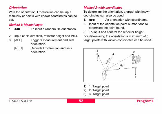
ith coordinates the orientation, a target with known
can also be used.As orientation with coordinates.
he orientation point number and to e the point found.and confirm the reflector height.ing the orientation a maximum of 5 with known coordinates can be used.
t pointt pointt point
52TPS400-5.0.1en
OrientationWith the orientation, Hz-direction can be input manually or points with known coordinates can be set.
Method 1: Manual input 1. To input a random Hz-orientation.
2. Input of Hz-direction, reflector height and PtID.3. [ALL] Triggers measurement and sets
orientation.[REC] Records Hz-direction and sets
orientation.
Method 2: wTo determinecoordinates 1.2. Input of t
determin3. To input For determintarget points
1) 1. Targe2) 2. Targe3) 3. Targe

TPS400-5.0.1en
e between horizontal distance to int computed from coordinates and ured distance.
uted orientation
puted Hz-orientation.
target point is measured then the puted using the "least squares
53Programs
Orientation coordinates can be either obtained from the internal memory or entered manually.The workflow is similar to Free Station workflow.After each measurement you are asked wether to proceed or not. Answering with yes brings you back to the Measurement dialog, to take an additional measurement. Answering with no brings you to the Result dialog.[COMPUTE] Calculates and displays the orienta-
tion results.[NextPt] Input another backsight point.1/I Status indication; shows that first point was
measured in telescope position I.1/I II First point measured in telescope pos. I and
II.Hz: After the first measurement the finding of
other target points (or the same point when changing the telescope position) is easier by setting the indicated angle difference near to 0°00'00" by turning the instrument.
: Differenctarget pothe meas
Display of comp
[OK] Set com
If more than oneorientation is commethod".

Programs
eight correctionorrection of the horizontal distanceorrection of Hz-angle.
54TPS400-5.0.1en
Displaying residuals[RESID] Display of residuals.
1) Actual2) Design
H: H: c
Hz: C

TPS400-5.0.1en
55ProgramsUseful information• If the orientation is only measured in telescope
position II the Hz-orientation is based on tele-scope position II. If measured only in telescope position I or mixed the Hz-orientation is based on telescope position I.
• The prism height may not be changed during measurements in the first and second telescope position.
• If a target point is measured several times in the same telescope position the last valid measure-ment is used for the computation.
If no orientation was set and an application was started resp. if in "Meas & Rec" [ALL] or [REC] was triggered, then the current Hz-direction and V-angle are set as orientation.

Programs
1. Press the [MENU] fixed key.
2. Selecting the "Program" option.
3. Calling up applications and acti-vating start programs.[PAGE] Scroll to next page.
56TPS400-5.0.1en
ApplicationsIntroductionApplications are predefined programs, that cover a wide spectrum of surveying duties and facilitate daily work in the field.The following applications are available:• Surveying• Setting Out• Tie Distance• Area & Volume• Free Station• Reference Line• Remote Height• Construction• Cogo (optional)• Reference Plane (optional)
[MENU]
-

TPS400-5.0.1en
thods are available:g = remark: /remark in the relevant field. These with the corresponding measure-LL]. The code is not related to a just a simple remark. A codelist on nt is not necessary.ding with codelist:
ODE] softkey. The code that was hed for within the code list and it is dd attributes to the code.re always stored as free codes eans that codes are not directly
Point codes (Wi71-79) are not
57Programs
SurveyingWith the program Surveying the measurement of an unlimited number of points is supported. It is compa-rable to "Meas & Rec", but includes stationing, orien-tation and coding.
Procedure:1. Input PtID, codes and the reflector height if
desired.2. [ALL] Triggers and records measure-
ments.[IndivPt] Switches between individual and
current point number.
Two coding me1. Simple codin
Input a codetext is storedment with [Acodelist, it isthe instrume
2. Expanded coPress the [Cinput is searcpossible to a
Codes a(Wi41-49), that mlinked to a point.available.

Programs
outation of polar stake out offsets Hz,
.
be stake outngle offset: positive if point to be set-ut is to the right of the actual direction.ongitudinal offset: positive if point to be take out is further away.eight offset: positive if point to be take out is higher than measured point.
58TPS400-5.0.1en
Stake outThis program calculates the required elements to stakeout points from coordinates or manually entered angles, horizontal distances and heights. Setting out differences can be displayed continu-ously.Setting out coordinates from memoryProcedure:
Select the point.[DIST] Starts measurement and calculation of
the stake-out elements.[REC] Saves the displayed values.[B&D] Input direction and Hz-distance of stake
out point.[MANUAL] Enables simplified input of a point
without PtID and without the possibility of storing the data of the point.
Polar Stake Normal indic
,
1) Actual2) Point to
Hz: Ao
: Ls
: Hs

TPS400-5.0.1en
outed on a coordinate system and the nto a north and east element.
take outffset between stake out and actual
offset between stake out and int.
59Programs
Orthogonal Stake outThe position offset between measured point and stake out point is indicated in a longitudinal and transversal element.
1) Actual2) Point to be stake out
L: Longitudinal offset: positive if nominal point further away.
T: Transversal offset, perpendicular to line-of-sight: positive if nominal point is to the right of measured point.
Cartesian StakeSetting out is basoffset is divided i
1) Actual2) Point to be s
E Easting opoint.
N Northingactual po

Programs
g measurements sequences to s are possible:V-angles only (resection) and Hz- and V-angle (3 point )
V-angles to some point(s) and Hz- and plus distance to other point(s).puted results are Easting, Northing
f the present instrument station, instruments Hz-circle orientation. viations and residuals for accuracy are provided.lation of the station, measured target re-measured, disabled and again
60TPS400-5.0.1en
Free StationThe application "Free Station" is used to determine the instrument position from measurements to a minimum of two known points and a maximum of five known points.
The followintarget point1. Hz- and 2. Distance
resection3. Hz- and
V-angle The final comand Height oincluding theStandard deassessmentsFor the calcupoints can beenabled.

TPS400-5.0.1en
cedurerocedure automatically determines aluation, e.g. resection, 3 point
minimum required measurements e processing routine uses a least
ent to determine the plan position ientation and heights.averaged face I and face II ts enter the computation process. ents are treated with the same
ether these are measured in single
northing is determined by the ast squares, including standard improvements for Hz-direction
al distances.ght (H) is computed from averaged nces based on the original ts. orientation is computed with the
aged face I and face II measure-e final computed plan position.
61Programs
Measuring facilitiesSingle face I or II or dual face I + II measurements are always possible. No specific point sequence or specific face sequences are required.Gross errors checks are made for dual face measurements to ensure the same point(s) are sighted with the other face.
If a target point is measured several times in the same telescope position the last valid measure-ment is used for computation.Measurement restrictions:• 2 face measurements
When measuring the same target in both faces, the reflector height may not be altered when changing the telescope position.
• Target points with 0.000 heightTarget points with 0.000 height are discarded for height processing. If target points have a valid height of 0.000 m, use 0.001 m to enable it for height processing.
Computation proThe measuring pthe method of evresection, etc.If more than the are performed, thsquares adjustmand averages or1. The original
measuremen2. All measurem
accuracy, whor dual face.
3. Easting and method of ledeviation andand horizont
4. The final heiheight differemeasuremen
5. The Hz-circleoriginal averments and th

Programs
enter a limit for the standard deviation r computed deviation exceeds the limit log appears, where you can decide ceed or not.
he name of the station and the height of ment.he target PtID and the reflector height.
Triggers angle and distance measurement (3 point resection).Saves Hz-direction and V-angle (resection).
62TPS400-5.0.1en
Procedure:
Enables you to define an accuracy limit.
Here you canvalues. If youa warning diawether to pro1. Input of t
the instru2. Input of t
[ALL]
[REC]

TPS400-5.0.1en
ated station coordinates:
witches to measurement display, o measure additional points.isplays residuals.isplays standard deviation.ets the displayed coordinates and
nstrument height as new station.
ESID StdDev OK
ION COORDINATES
: 100 : 1.500 : 100.506 : 100.040: 99.999
63Programs
[AddPt] Input another backsight point.[COMPUTE] Calculates and displays the station
coordinates, if at least 2 points and a distance were measured.
3/I Indicates that the third point in tele-scope position I was measured.
3/I II Indicates that the third point in tele-scope positions I and II.
ResultsDisplays calcul
[PREV] St
[RESID] D[StdDev] D[OK] S
i
PREV R
STAT
Station hi EO NO HO

Programs
shows the computed residuals:alculated value - Measured value
Switches to measurement display, to measure additional points.Remeasures the displayed point.Always sets the displayed coordi-nates and instrument height as new station.
Re-Meas OK
RGET RESIDUALS 3/3
: 300 : -0.0096 g : -0.019 g : 0.001 g
64TPS400-5.0.1en
If the instrument height was set to 0.000 in the setup screen, then the station height refers to height of trunnion axis.Displays standard deviations:
Std.Dev E0, N0, H0 Standard deviation of the station coordinates
Std.Dev Ang Standard deviation of the orien-tation
This dialog Residual = C
[PREV]
[Re-Meas][OK]
PREV OK
STATION STANDARD-DEVITION
Std.Dev.EO : 0.027 Std.Dev.NO : 0.013 Std.Dev.HO : 0.000 Std.Dev.Ang: +0.0121
PREV
TA
PtID Hz

TPS400-5.0.1en
65Programs[Disable]/[Enable]Excludes/includes the displayed point from/in the calculations. Recalculates the free station and displays the station standard devia-tion. Press [PREV] to display the new station coordinates.
[StdDev] Displays standard deviation.With the function keys, scroll between the residuals of the indi-vidual backsight points.

Programs
Meaning
cted target point has no easting or northing
asured and another point is selected. The 5 points.
w final station coordinates (Eastings, North-
d or insufficient measurements are available .
nd does not allow further storage.
easured in one face and the measurement than 180° ±0.9° for the horizontal angle.
easured in one face and the measurement in n 360° - V ±0.9° for the vertical angle.
red to be able to compute a position. Either d or not enough distances measured.
66TPS400-5.0.1en
Warnings / Messages
Important messages
Selected point has no valid data ! This message occurs if the selecoordinate.
Max 5 points supported ! If 5 points have already been mesystem supports a maximum of
Invalid data - no position computed ! The measurements may not alloings) to be computed.
Invalid data - no height computed ! Either the target height are invalito compute a final station height
Insufficient space in job ! The present selected job is full a
Hz (I - II) > 0.9 deg, measure point again ! This error occurs if a point was min the other face differs by more
V (I - II) > 0.9 deg, measure point again ! This error occurs if a point was mthe other face differs by more tha
More points or distance required ! There is insufficient data measuthere are not enough points use

TPS400-5.0.1en
anually input coordinates.isplays the list of available points.
ure for the second base point.
tint
e
67Programs
Reference LineThis program facilitates the easy stake out or checking of lines for buildings, sections of road, simple excavations, etc.A reference line can be defined by referencing a known base line. The reference line can be offset either longitudinally, in parallel or vertically to the base line, or be rotated around the first base point as required.
Procedure:
1. Definition of the Base line:The base line is fixed by two base points that can be defined in three ways:• Measured points• Enter coordinates using keypad• Select point from memory.a) Measuring base points:
Input PtID and measure base points with [ALL] or [DIST] / [REC].
b) Base points with coordinates:[FIND] Starts to search for the PtID
entered.
[ENH] M[LIST] D
Analogue proced
1) 1st base poin2) 2nd base po3) Base line4) Reference lin
TPS800_Z36

Programs
llel offsetitudinal offsettion parameter parameters:the navigation keys to select the ng and rotation parameters of the refer- line.
68TPS400-5.0.1en
2. Shifting/Rotating the Base lineThe base line can be offset longitudinally, parallel and vertically or rotated. This new line is called the reference line. All measured data refers to the refer-ence line.
BP: Base pointBL: Base lineRP: Reference pointRL: Reference line
Off: ParaL: LongR: RotaInput of the
Use shiftience
BP1
BP2
BL
RP
RL
R+
L+
Off+TPS800_Z37

TPS400-5.0.1en
subapplicationtarts the subapplication to measure ine & Offset (see issue 4).tarts the subapplication to stake ut (see issue 5).
" subapplicationet" subapplication calculates from r coordinates longitudinal, parallel t differences of the target point erence line.
69Programs
The following entries are possible:Offset+: Parallel offset of the reference line
to the right, referred to the direction of the base line (BP1-BP2).
Line+: Longitudinal offset of the start point (=reference point) of the reference line in the direction of base point BP2.
Rotate+: Rotation of the reference line clock-wise around the reference point.
Height+: Height offset; the reference line is higher than the selected reference height.
3. Selecting the [MEASURE] S
L[STAKE] S
o
4. "Line & OffsetThe "Line & Offsmeasurements ooffsets and heighrelative to the ref
NewBL MEASURE STAKE SHIFT=0
REFERENCE LINE - MAIN 1/2 Length : 14.872 mEnter values to shift line:Offset : 1.000 mLine : 0.500 mHeight : 0.900 mRotate : 25.0000 g

Programs
f the first reference point is always used nce height for the calculation of the nces ( ).
IR
IDIST REC
140 1.500 m 0.208 m 0.349 m 1.203 m
REFERENCE LINE
70TPS400-5.0.1en
1RP: 1st reference pointMP: Measured pointRL: Reference line
L: Longitudinal offsetOff: Parallel offset
The height oas the refereheight differe
1RP
MPL+
Off+
TPS800_Z38
RL
PtID :hr : Offset: Line : :

TPS400-5.0.1en
bapplicationngitudinal, parallel and height get points to be set-out relative to . The program calculates the differ-
measured point and the calculated m displays the orthogonal ( Line, ) and the polar ( Hz, , es.
ogonal stake out elements. entry and start calculation.
71Programs
Example "relative to first reference point"
1RP: 1st reference point1BP: 1st base pointRH: Reference heightHd: Height difference between reference and
base pointH: Height difference from reference height
5. "Stake out" suYou can enter looffsets for the tarthe reference lineence between a point. The progra
Offset, ) differenc
Procedure:1. Input the orth2. [OK] Confirm
H+
H-
1BP
1RP RH
Hd+
TPS800_Z39

Programs
Stake out" measure mode:
the distance and angle differences are lues (required minus actual).urn telescope clockwise to the stake ut point.he stake out point is further away than
he point measured.
IR
IDIST REC
15 1.500 m +0.200 g 2.368 m 0.260 m
OGONAL STAKEOUT 1/2
2.040 m 1.203 m 0.260 m
72TPS400-5.0.1en
Example "orthogonal stake out"
1RP: 1st reference pointRL: Reference lineMP: Measured pointSP: Stake out point
L: Longitudinal offsetOff: Parallel offset
Display in "
The signs forcorrection va+ Hz T
o+ T
t
1RP
RL
SP
MP
TPS800_Z40
L-
O-
PtID :hr : Hz : : :
ORTH
Offset: Line : :

TPS400-5.0.1en
ie Distance computes slope tal distance, height difference and rget points measured online, Memory or entered using the
ose between two different
l (A-B, B-C)-B, A-C)od:
73Programs
+ The stake out point is higher than the measured point.
Warnings / Messages
Tie DistanceThe application Tdistance, horizonazimuth of two taselected from theKeypad. The user can chomethods:
PolygonaRadial (A
Polygonal Meth
Important Messages Meaning
Save via RS232 !
Data output (system setting menu) via RS232 interface is activated. To be able to succesfully start reference line, the "INTERN" setting must be enabled.
Base line too short !
Base line is shorter than 1 cm. Choose base points such that the horizontal separation of both points is at least 1 cm.
Coordinates invalid !
No coordinates or invalid coordinates for a point. Ensure that a point used has at least one Easting and one Northing co-ordinate.

Programs
displayed.Azimuth between point1 and point2.
Slope distance between point1 and point2.Horizontal distance between point1 and point2.Height difference between point1 and point2.Grade [%] between point1 and point2.
olygonal method:An additional missing line is computed. Program starts again (at point 1).Point 2 is set as starting point of a new missing line. New point (Pt 2) must be measured.Switches to radial method.
74TPS400-5.0.1en
Radial Method:
In principal both methods are the same.Any differences will be described.Procedure:1. Determine first target point.
[ALL] Starts measurement to the target point.
[FIND] Searches internal memory for point entered.
2. Determine second target point.Proceed as with first target point.
3. Result isBrg
Grade
Softkeys - p[NewPt 1]
[NewPt 2]
[RADIAL]
Centre point
Slope distance 1-2Slope distance 1-3
Slope distance 1-4

TPS400-5.0.1en
75ProgramsSoftkeys - radial method:[NewPt 1] Determine new central point.[NewPt 2] Determine new radial point.[POLY] Switch to polygonal method.

Programs
r, polygonal length from start point to nt measured point.d area always closed to the start point cted onto the horizontal plane.
P3 Target pointnt P4 Target pointoint
P2 P3
P4
b
76TPS400-5.0.1en
Area & VolumeThe application program Area is used to compute online areas of max. 50 points connected by straights. The target points have to be measured, selected from memory or entered via keyboard in clockwise direction. The calculated area is projected onto the horizontal plane (2D) or projected onto the sloped reference plane defined by 3 points (3D). Furthermore a volume with constant height can be calculated in relation to the area (2D/3D).
a Perimetethe curre
b CalculateP1, proje
P0 StationP1 Start poiP2 Target p
P1
a
P0

TPS400-5.0.1en
o define the sloped reference lane by selecting or measuring
hree points.o calculate a volume with constant eight. The height have to be ntered or measured.o display and record additional esults (perimeter, volume).eter and volume are updated if
points are added.graphic shows always the area to the horizontal plane.
77Programs
1. Determine area points[ALL] Starts the measurement to the
point.[FIND] / Searches for point in internal[LIST] memory.[ENH] For manual input of the coordinates.[1PtBACK] Undo measurement or selection of
last point.The area (2D) is calculated and displayed
once three points have been measured or selected. The area (3D) is calculated once the sloped refer-ence plane is defined by three points.
2. Results[Def. 3D] T
pt
[VOLUME] The
[RESULT] Tr
Perimfurther area
The projected on

Programs
oint which defines the sloped reference
oint which defines the sloped reference
oint which defines the sloped reference
ointt heightr (3D), polygonal length from the start he current measured point of the area
), projected onto the sloped reference
(3D) = a x cr (2D), polygonal length from the start he current measured point of the area
), projected onto the horizontal plane(2D) = f x a
78TPS400-5.0.1en
P0 StationP1 Target p
planeP2 Target p
planeP3 Target p
planeP4 Target pa Constanb Perimete
point to t(3D)
c Area (3Dplane
d Volume e Perimete
point to t(2D)
f Area (2Dg Volume
TPS800_Z101
P1
a
a
P2P3
P4
P0
c db
f eg

TPS400-5.0.1en
nd reflector heighttarts measurement to base point nd continues to 2.tarts the program that determines n unknown reflector height.essible height pointaves the measured data.
nput and measurement of a new ase point.
79Programs
Remote HeightPoints directly above the base prism can be deter-mined without a prism at the target point.
1) Remote point2) Height diff.3) Slope distance4) Base point
Procedure:1. Input PtID a
[ALL] Sa
[hr?] Sa
2. Aim at inacc[OK] S[BASE] I
b

Programs
Allows you to enter values for shifting the line.Switches to Layout-mode.
itive:int is in direction from line start - to line
sitive:int is right of line.
ositive:
A111.500 m7.225 m
10.194 m-1.673 m
80TPS400-5.0.1en
ConstructionThis application allows to define a construction site by combining set-up of the instrument along a construction line, measuring and setting out points in relation to the line.After selecting the application you have two options:a) Defining a new construction site
orb) Continue with previous site (skips set-up)Procedure:Defining new site:1. Measure line Start point [ALL], [DIST]+[REC]2. Measure second line point [ALL], [DIST]+[REC]
In case, you have entered coordinates by ENH and measured to known points a plausibility check informs you about the calculated line length, the actual length and the difference.As built check:This dialog shows you the Line, Offset and
Height of a measured point in relation to the line.
[ShiftLn]
[LAYOUT]
Line is posMeasured poend point.
Offset is poMeasured po
Height is p
PtID : hr : : Off: :

TPS400-5.0.1en
w you the position of the prism ke out point. Below, the exact yed, combined with arrows to show
(arrow up):rther away than the measured
e (arrow right):ght of the measured point.
ve (arrow up):igher than the measured point.ht of the line start point is always ence height!hics are scaled to give a better ore it’s possible that the station e graphics. that the line start point and the line asured in the previous coordinate aking out this points they appear in nd appear as shifted.
81Programs
Measured point height is above line start point’s height.
The height of the line start point is always used as the reference height!LayoutHere you can search or enter points for staking out related to the measured line.
[ShiftLn] Allows you to enter values for shifting the line.
[AsBUILT] Switches to AsBuilt-mode.
The graphics shorelated to the stavalues are displathe direction.
Line is positiveTarget point is fupoint.
Offset is positivTarget point is ri
Height is positiTarget point is h
The heigused as the refer
The grapoverview. Therefpoint moves in th
Be awareend point are mesystem. When stthe old system a

Programs
onal)application COGO can be started in s for trial. Afterwards you have to enter ode. application program to perform coordi-ry calculations such as:tes of points between pointss between pointsalculation methods are: Traverse
ions
n
umps to the Measurement dialog to easure the point.tarts the calculation, when all required ata is entered.hen the calculated point is displayed
ou have the option to stake out this oint directly.
82TPS400-5.0.1en
During use of the application the previous Orientation and Station parameters will be replaced by the new calculated ones.
COGO (optiThe
total 15 timethe license cCOGO is annate geomet• coordina• bearings• distanceThe COGO c• Inverse &• Intersect• Offset• ExtensioSoftkeys:[MEAS] J
m[Calc] S
d[STAKE] W
yp

TPS400-5.0.1en
P1 to P2ween P1 and P2t to the rightet to the left
without offset with positive offset with negative offset
d1
d2
d3
P1
P3
P2
P4
83Programs
Inverse & TraverseInverse
KnownP1 First known pointP2 Second known pointUnknowna Direction from P1 to P2d1 Slope distance between P1 and P2d2 Horizontal distance between P1 and P2d3 Height difference between P1 and P2
Traverse
KnownP1 Known pointa Direction fromd1 Distance betd2 Positive offsed3 Negative offsUnknownP2 COGO pointP3 COGO pointP4 COGO point
TPS800_Z86
d1d3
d2
P1
P2
TPS800_Z87

Programs
stance
wn pointknown point from P1 to P3 and P4as defined by the distance from P2 to 3
GO pointCOGO point
r
P1
P2
P4
P3
84TPS400-5.0.1en
IntersectionsBearing - Bearing
KnownP1 First known pointP2 Second known pointa1 Direction from P1 to P3a2 Direction from P2 to P3UnknownP3 COGO point
Bearing - Di
KnownP1 First knoP2 Second a Directionr Radius,
P4 and PUnknownP3 First COP4 Second
TPS800_Z88
P1
P2
P31
2
TPS800_Z89

TPS400-5.0.1en
ointn point
pointn point to P2 to P4
a
b
P1
P2
P3
P4
P5
85Programs
Distance - Distance
KnownP1 First known pointP2 Second known pointr1 Radius, as defined by the distance from P1 to
P3 or P4r2 Radius, as defined by the distance from P2 to
P3 or P4UnknownP3 First COGO pointP4 Second COGO point
By Points
KnownP1 First known pP2 Second knowP3 Third knownP4 Fourth knowa Line from P1b Line from P3UnknownP5 COGO point
TPS800_Z90
r1
r2
P1
P2P3
P4
TPS800_Z91

Programs
...
start point end pointe in length/abzissa (HD)eviation/ordinate (Offset)
oint
ab
P1
P2
P3
86TPS400-5.0.1en
OffsetDistance - Offset
KnownP1 Baseline start pointP2 Baseline end pointP3 Lateral pointUnknownd1 Difference in length/abzissa (HD)d2 Lateral deviation/ordinate (Offset)P4 Base point
Set Point by
KnownP1 BaselineP2 Baselinea Differencb Lateral dUnknownP3 Lateral p
TPS800_Z92
d1
d2
P1
P2
P3
P4
TPS800_Z93

TPS400-5.0.1en
routine computes extend point from
aseline start pointaseline end pointistance
xtended point
P1
P2
P3
P4
ΔL1
ΔL2
87Programs
Plane Offset
KnownP1 Point 1 which defines planeP2 Point 2 which defines planeP3 Point 3 which defines planeP4 Offset pointUnknownP5 COGO pointd1 Offset
ExtensionThe "Extension" base line.
KnownP1 BP3 B
L1 or L2 DUnknownP2, P4 E
TPS800_Z159
d1
P1
P3
P2
P4
P5

Programs
point is the origin of a local coordinate
nd point defines the direction of the xis. point defines the plane.
point, origin of local coordinate systemnd point point
Z
Y
b
X
P52P3
P4
147
Off+
�X�Z
88TPS400-5.0.1en
Reference Plane (optional)The application Reference Plane can be
trialed 15 times. Afterwards it is necessary to enter the license code.
The Reference Plane application is used to measure points relative to a reference plane. It can be used for the following tasks:• Measuring a point to calculate and store the
perpendicular offset to the plane.• Calculating the perpendicular distance from the
intersection point to the local X- and Z-axis. The intersection point is the footprint point of the perpendicular vector from the measured point through the defined plane.
• Viewing, storing and staking out the coordinates of the intersection point.
A reference plane is created by measuring three points on a plane. These three points define a local coordinate system:
• The first system.
• The secolocal Z-a
• The third
P1 FirstP2 SecoP3 Third
a
P1
P
TPS800_Z
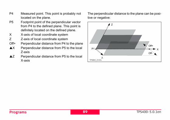
TPS400-5.0.1en
r distance to the plane can be posi-
Z
XOff+
Off-
89Programs
P4 Measured point. This point is probably not located on the plane.
P5 Footprint point of the perpendicular vector from P4 to the defined plane. This point is definitely located on the defined plane.
X X-axis of local coordinate systemZ Z-axis of local coordinate systemOff+ Perpendicular distance from P4 to the plane
X Perpendicular distance from P5 to the local Z-axis
Z Perpendicular distance from P5 to the local X-axis
The perpendiculative or negative:
Y
P1
TPS800_Z147a

Programs
Displays the list of available points.Opens the coordinate input mode.
target pointrget point as you usually survey points.
Point ID of the intersection point, the perpendicular projection of the target point on the plane.
PLANE RESULT 1/2
: 104 : 1.380 m : 4.500 m : 2.000 m
STAKE NewPlan EXIT
90TPS400-5.0.1en
Procedure
1. Measuring points defining the reference plane
Input the name of the first point on the reference plane and the height of the reflector. Measure the point.Repeat this for the second and the third point on the reference plane.[FIND] Starts point search. Exact PtIDs can
be entered or the * wildcard-criteria used.
[LIST][ENH]
2. MeasuringMeasure a ta
3. Results
Int. PtID:
ALL FIND LIST
PLANE 1/3 Measure 1st plane point !Point 1 : A1Point 2 : -----Point 3 : -----hr : 1.500 m : -----.--- m : -----.--- m
IR
IInt.PtID X Z
NewTgt

TPS400-5.0.1en
formation about recorded points. oding, points can be assigned to a
simplifying later processing. on coding can be found under
ent".
mel remarkely editable on
re always stored as free codes eans that codes are not directly
They are stored before or after the pending on the setting made. 1-79) are not available.
91Programs
Offset: Calculated perpendicular distance between target point and plane (intersection point).
X: Perpendicular distance from the intersection point to the local Z-axis.
Z: Perpendicular distance from the intersection point to the local X-axis. The stake out point is higher than the origin of the coordinate system.
[New Tgt] To measure a new target point.[STAKE] To display stake out values for the
intersection point.[New Plane] To define a new reference plane.[EXIT] Goes to the programs menu.
CodingCodes contain inWith the help of cparticular group More information"Data managem
GSI-codingCode: Code naDesc.: AdditionaInfo1: more, fre... informatiInfo8: lines
Codes a(Wi41-49), that mlinked to a point.measurement dePoint codes (Wi7

Programs
essages
idually entered code blocks are not code list.ffice Tools (LGO-Tools) be easily created and uploaded to the
sing the supplied "LGO-Tools" Soft-
ant es Meaning
be Attribute with fixed status cannot be changed.
vailable !No codelist in memory. Manual input for code and attributes are called automatically.
d ! Code missing. Extend input.
92TPS400-5.0.1en
Procedure:Select code from a codelist or enter a new code:[RECORD] The code is directly recorded without a
measurement with [ALL].[OK] The code is set. After a measurement
with [ALL] the code is recorded.[AddList] Adds the entered code to the codelist.
Extending / editing code1. Call available code from code list.2. Attributes can be overwritten freely.Exceptions:With the codelist editor of LGO/LGO-Tools a status can be assigned to the attributes.• Attributes with "fixed status" (see LGO/LGO-
Tools) are write-protected. They cannot be over-written or edited.
• For attributes with status "Mandatory" an input or a confirmation is required.
• Attributes with status "Normal" can be edited freely.
Warnings / M
Indivadded to theLeica Geo OCodelists caninstrument uware.
ImportMessag
Attrib. cannotchanged !
No codelist a
Entry require

TPS400-5.0.1en
nith=0°; Horizon=90°nith=90°; Horizon=0°°=100%; Horizon=0°
alue increases rapidly. "--.--%" isplay above 300%".
g compensation switched off.gles relate to the plumb line.gle refer to the plummet line and z-directions are corrected by the
ding axis tilt.
is used on an unstable base (e.g. , ship, etc.) the compensator should
ompensator drifting out of it's and interrupting the measuring ting an error.
pensator setting remains active strument is switched off.
93Settings
SettingsThis menu enables extensive user-specific settings in order to adapt the instrument to their own require-ments.ContrastSetting the display contrast in 10% steps.Trigger keyConfiguration of the trigger key on side cover.Off Trigger key deactivated.ALL Trigger key with same function as
the [ALL]-key.DIST Trigger key with same function as
the [DIST]-key.USER KeyConfigure the USER Key with a function from the FNC-menu.V-SettingThe "0"- orientation of the vertical circle can be either selected for the zenith, the horizontal plane or in %.
• Zenith: Ze• Horizon: Ze• V-(%): 45
The % vappears on the dTilt CorrectionOff Tiltin1-axis V-an2-axis V-an
the Hstan
If the instrumentshaking platformbe switched off.This avoids the cmeasuring rangeprocess by indica
The comeven after the in

Settings
p (interrupted)nt beep
94TPS400-5.0.1en
Sector Beep Off Sector Beep switched offOn Sector Beep sounds at right angles (0°,
90°, 180°, 270° or 0, 100, 200, 300 gon)Example Sector Beep:From 95.0 to 99.5 gon (or from 105.0 to 100.5 gon) a "Fast beep" sounds whilst from 99.5 to 99.995 gon (or from 100.5 to 100.005 gon) a "Permanent beep" sounds.
1) No beep2) Fast bee3) Permane

TPS400-5.0.1en
tomatically activated when the ay illumination is on and the instru-t temperature is ≤ 5°C.
ed languages are shown.e
are loaded onto the instrument a the language can be shown directly n the instrument.language dialog is shown as up dialog.language dialog is not shown as up dialog.
is recorded via the serial interface. setting in only required if an rnal storage device is connected measurements are started at the with DIST/REC or ALL. This setting t required if the TPS is totally rolled by a datalogger.
95Settings
BeepThe beep is an acoustic signal after each key stroke.Off Beep switched offNormal Normal volumeLoud Increased volumeHz IncrementationRight Set right Hz for "Clockwise direction
measurement".Left Set left Hz for "Counter-clockwise direc-
tion measurement". "Counter-clock-wise" directions are only displayed but saved as "Clockwise direction".
Reticle IlluminationThe reticle illumination is only switched on if the display illumination is on.Low Low illuminationMedium Medium illumination High High illumination
DSP HeaterOn Is au
displmen
LanguageThe current loadLanguage choicIf two languagesdialog to choose after switching oOn The
startOff The
startData OutputRS232 Data
Thisexteand TPSis nocont

Settings
Collimation ON" is active, each z-angle is corrected (depending on
peration the Hz-collimation remains
information on Hz-collimation can be "Adjusments".
he instrument is switched off after 20 inutes without any action (= no key ressed; V and Hz angle deviation ±3' / ±600cc). he instrument is switched on perma-ently. Battery discharges quicker.conomy mode. Instrument is recov-red by any key stroke.
degree sexagesimal)ossible angle values: 0° to 359°59'59''degree decimal)ossible angle values: 0° to 359.999°
96TPS400-5.0.1en
Intern All data is recorded in the internal memory.
GSI 8/16Select GSI output format.GSI 8: 81..00+12345678GSI 16: 81..00+1234567890123456Mask 1/2/3Select GSI output mask.Mask 1: PtID, Hz, V, SD, ppm+mm, hr, hiMask 2: PtID, Hz, V, SD, E, N, H, hrMask 3: StationID, E, N, H, hi (Station)
StationID, Ori, E, N, H, hi (Station Result)PtID, E, N, H (Control)PtID, Hz, V (Set Azimuth)PtID, Hz, V, SD, ppm+mm, hr, E, N, H (Measurement)
Hz CollimationOn Hz Collimation is switched ON. Off Hz Collimation is switched OFF.
If option "Hzmeasured HV-angle). For normal oswitched on.
Morefound under Auto-OFFEnable T
mp≤
Disable Tn
Sleep Ee
Angle Unit° ' " (
pdeg.dec (
p

TPS400-5.0.1en
thod
ethod
reet-Inch-1/16 incheetnational feet
lays distance with three decimalslays distance with four decimals
ee Celsiusee Fahrenheit
aro Pascaleter mercury column
mercury column
97Settings
gon possible angle values: 0 gon to 399.999 gon
mil possible angle values: 0 to 6399.99mil
The setting of the angle units can be changed at any time.The actual displayed values are converted according to the selected unit.Min. ReadingThe displayed angle format can be selected in three steps.• For 360°'":
0° 00' 01" / 0° 00' 05" / 0° 00' 10"Always " are indicated.
• For 360°:0.0001° / 0.0005° / 0.001°
• For gon:0.0001 gon / 0.0005 gon / 0.001 gon
• For mil:0.01 mil / 0.05 mil / 0.10 mil
Input methodHere you can select the method to input alphanu-meric characters.
• Method 1Standard me
• Method 2Advanced m
Distance Unitmeter Meteft-in1/16 US-fUS-ft US-fINT-ft InterDistance Digits3 Disp4 DispTemperature°C Degr°F DegrPressurembar MillibhPa HectmmHg MilliminHg Inch

EDM Settings
truments different settings for ts with reflectorless (RL) and reflector de are available.n selected measuring mode the selec-es are different.
Fine measuring mode for high precision measurements with prisms(2mm + 2 ppm)
Quick measuring mode with higher measuring speed and reduced accuracy (5mm + 2 ppm)
Continuous distance measuring (5mm + 2 ppm)
Distance measurement using Retro targets(5mm + 2 ppm)
98TPS400-5.0.1en
EDM SettingsThe EDM-settings contain a detailed menu with selection boxes.
EDM ModeWith TCR insmeasuremen(IR) EDM moDepending otion prism typ
IR-Fine
IR-Fast
IR-Track
IR-Tape

TPS400-5.0.1en
+23.1
+30.0
+17.5
+34.4 Mini prism
+34.4
--is set at "Prismconst" (-mm + 34.4; e.g.: mm = 14 -> input = -14 + 34.4 = 20.4)
+34.4 Reflectorless
99EDM Settings
With the RL-EDM each object in the beam is measured (possibly also branches, cars, etc.).Prism typeCalling the function in the EDM settings.
RL-StandardFor distance measurements without prisms (≤500m: 2mm + 2ppm>500m: 4mm + 2ppm)
RL-TrackContinuous distance measure-ment without prisms(5mm + 3 ppm)
RL-Prism For distance measurements with prisms
Leica Prisms
Constants[mm]
Standard prism (Round)GPH1 + GPR1
0.0
360° prism GRZ4
360° Mini prism GRZ101
MiniprismGMP101/102
JPMINIReflective targets
USER
RL

EDM Settings
red diode yellow diodee: 5 - 150 m (15 -500 ft)
12 m (40 ft) at 100 m (330 ft)
6 m(20 ft)
6 m(20 ft)
100
m (
300
ft)
100TPS400-5.0.1en
Prism ConstantCalling the function in the EDM settings.Entry of a user specific prism constant. Input can only be made in [mm].Limit value: -999,9 mm to +999,9 mmLaser PointerOff: Visible laser beam is switched off.On: Visible laser beam for visualising the target
point is switched on.Guide Light The person at the prism can be guided by the flashing lights directly to the line of sight. The light points are visible up to a distance of 150 meters. This is useful when setting out points.
1) Flashing2) FlashingOperat. rangDivergence:

TPS400-5.0.1en
eric parameters.
ameters (ppm):ement is influenced directly by the ditions of the air in which distance e taken.
nto consideration these influences ements are corrected using atmo-n parameters.
101EDM Settings
[SCALE]Scale of projection.
Scale factor:Entering the scale of projection. Measured values and coordinates are corrected with the PPM param-eter.[PPM=0] Sets default parameters.[PPM]Input of individual scaling parameters.
[ATMOS]Input of atmosph
Atmospheric ParDistance measuratmospheric conmeasurement ar
In order to take idistance measurspheric correctio

EDM Settings
102TPS400-5.0.1en• Ht. a. MSLHeight above sea level at instrument location.
• TemperatureAir temperature at instrument location.
• Pressure Air pressure at instrument location.
• Atmos PPM:Calculated and indicated atmospheric PPM.
Signal[SIGNAL] Displays EDM signal strength (reflection
strength) in steps of 1%. Permits optimal aiming at distant barely visible targets.
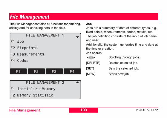
TPS400-5.0.1en
ary of data of different types, e.g. surements, codes, results, etc. consists of the input of job name
system generates time and date at ion.
crolling through jobs.
eletes selected job.
ets the selected job.
tarts new job.
103File Management
File ManagementThe File Manager contains all functions for entering, editing and for checking data in the field.
JobJobs are a summfixed points, meaThe job definitionand user. Additionally, the the time or creatJob search:
S
[DELETE] D
[SET] S
[NEW] S

File Management
Save data.Starts search dialogue.Input of attributes.
mory, single data areas of a job or all
104TPS400-5.0.1en
FixpointsValid fixed points contain at least the PtID and the coordinates (E, N) or (H).[DELETE] Deletes selected fixed point.[FIND] Starts point search. Exact PtIDs can
be entered or the * wildcard-criteria used.
[NEW] Opens input for PtID and coordi-nates.
MeasurementsMeasurement data available in the internal memory can be searched and displayed or erased.[FIND] Starts point search dialogue.[VIEW] Displays all measurements.CodesTo each code a description and a maximum of 8 attributes with up to 16 characters can be assigned.
[SAVE][VIEW][ATTRIB]
Initialize MeDeletes jobsdata.

TPS400-5.0.1en
105File Management[DELETE] Starts deleting process within the selected area.
[ALL] Deletes all data in memory. All data will be lost !
Deleting the memory cannot be undone. After confirming the message all data is deleted permanently.Memory StatisticDisplays job specific memory information such as:• Number of stored fixpoints.• Number of recorded data blocks (measured
points, codes, etc.).• Number of free or not defined jobs.

Start-up sequence
ing the dialogue of notification, the " screen is displayed. A maximum of 16 y presses are stored. The sequence is SC]. If the start sequence is activated, y presses are executed automatically trument is switched on.automatic start sequence has the same ssing the keys manually. Certain instru- can not be made in this way. "Relative as automatically setting "IR-FINE" ng on the instrument, are not possible.
106TPS400-5.0.1en
Start-up sequenceSets the screen the instrument starts in when switched on. E.g. the electronic bubble can be displayed at every start.
[OK] Stores current settings.[RECORD] Defines the key presses that are
executed automatically upon start up.
Procedure:After confirm"Meas & Recof the next keended with [Ethe stored kewhen the ins
The effect as prement settingsentries" suchupon switchi

TPS400-5.0.1en
rors should be determined before used for the first time, before preci-er long periods of transport, before riods of work, and if the tempera-more than 10°C (18°F).e determining the instrument , level-up the instrument using the onic bubble. The instrument should cure and firm, and should be irect sunlight in order to avoid n on one side only.
107Calibrations
CalibrationsDetermining Line-of-sight error and V-IndexThe calibration contains the determination of the following instrument errors:• Hz-collimation• V-index (simultaneously electronic level)For determining the Hz-collimation or the V-index it is necessary to measure in both telescope positions. The procedure can be started in any telescope posi-tion. The user is guided clearly through the procedure. A wrong determination of instrument error is thus elim-inated.The instruments are adjusted in the factory prior to shipping.Instrument errors can change with time and temper-ature.
These erthe instrument ission surveys, aftand after long peture changes by
Beforerrorselectrbe se
protected from dthermal expansio

Calibrations
Vertical index error)
ircle should read exactly 90° (100 gon) of sight is horizontal. Any deviation re is termed vertical index error (i).ng the vertical index error the electronic ted automatically.edures and conditions required to f-sight and height index errors are the
the procedure will only be described
108TPS400-5.0.1en
Line-of-sight error (Hz-collimation)
The line-of-sight error or collimation error (C) is the deviation from the perpendicular between the tilting axis and the line of sight.The effect of the line-of-sight error to the Hz-angle increases with the vertical angle.For horizontal aimings the error of Hz equals the line-of-sight error.
V-Index (
The vertical cwhen the linefrom this figuBy determinilevel is adjus
Proccorrect line-osame. Thus once.

TPS400-5.0.1en
cope position and aim to the point
horizontal aiming Hz and V are
measurement old and new calculated values.ets new calibration data.uits program without setting new
alibration data.
109Calibrations
Hz-collimationV-indexDisplay adjustment value: Summarizes saved values.
Procedure:1. Level instrument with electronic bubble. 2. Aim at a point approximately 100m from the
instrument which is within 5° of the horizontal.
3. [ALL]: Trigger measurement.
4. Change telesagain.
For checking thedisplayed.
5. [ALL]: Starts6. Displays the
[SET] S[ESC] Q
c

Calibrations
Measures
Aim on the target point with an accuracy of min. 5 gon. The target point must be approximately in the horizontal plane.Confirmation of the message required.
Repeat measurements.Confirmation of the message required.
Aim on the target point with an accuracy of min. 5 gon. Confirmation of the message required.
Repeat the process.Confirmation of the message required.
110TPS400-5.0.1en
Warnings / Messages
Important Messages Meaning
V-Angle not suitable for calibration (Check V-angle or face) !
Aiming tolerance not met or telescope posi-tion/face not changed.
Calibration result out of tolerance. Previous values retained !
Computed values out of tolerance. Previous values retained.
Hz-Angle out of limit !Hz-angle in second face/telescope pos. deviates more than 5 gon from the target point.
Measurement Error. Try again.
Measurement error appeared (e.g. instable set up or period between measuring in tele-scope position I and II too long).
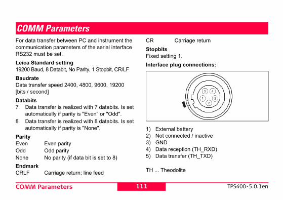
TPS400-5.0.1en
iage return
onnections:
eryd / inactive
n (TH_RXD)r (TH_TXD)
111COMM Parameters
COMM ParametersFor data transfer between PC and instrument the communication parameters of the serial interface RS232 must be set.Leica Standard setting19200 Baud, 8 Databit, No Parity, 1 Stopbit, CR/LFBaudrateData transfer speed 2400, 4800, 9600, 19200 [bits / second]Databits7 Data transfer is realized with 7 databits. Is set
automatically if parity is "Even" or "Odd".8 Data transfer is realized with 8 databits. Is set
automatically if parity is "None".ParityEven Even parityOdd Odd parityNone No parity (if data bit is set to 8)EndmarkCRLF Carriage return; line feed
CR CarrStopbitsFixed setting 1.Interface plug c
1) External batt2) Not connecte3) GND 4) Data receptio5) Data transfe
TH ... Theodolite

Data Transfer
736 83..00+000000911700 receiver is to slow in processing data d be lost. With this type of data transfer nt is not informed about the perfor- receiver (no protocol).
PtIDHorizontal directionVertical angleOrientationSlope distanceHorizontal distanceHeight differenceCodes and attributesppm [mm]Prism constants(E, N, H) Target point(E, N, H) Stand pointReflector heightInstrument height
112TPS400-5.0.1en
Data TransferWith this special function measured data can be trans-ferred via the serial interface to a receiver (e.g. a Laptop). Using this type of transfer the success of the transfer is not checked.Job: Selection of job from which data should
be transferred.Data: Select the data range to be transferred
(measurements, fixed points)Format: Select output format. Select Leica-GSI-
format, or your own format created in the "Format Manager" and transfer to the LGO/LGO-Tools.
[SEND] Starts the transmission.
Example:Within the "data" setting "MEASUREMENTS" a data set could be shown as follows:11....+00000D19 21..022+1664182622..022+09635023 31..00+0000664958..16+00000344 81..00+00003342
82..00-0000587..10+0000
If thethe data coulthe instrumemance of theGSI-ID’s1121222531323341-49515881-8384-868788

TPS400-5.0.1en
software of the instrument is posed of different software pack-. Depending on the package, rent versions are possible.ystem: Operating System
-SW: Applications, functionsand menu
ut: User displays
113System Info
System InfoDisplays helpful information and date / time are set.
• BatteryRemaining battery power (e.g. 40%).
• Instr.Temp.Measured instrument temperature.
• DateDisplays the current date.
• TimeDisplays current time.
[DATE] Change date and format.Format: There are three display formats:
DD.MM.YYYYMM.DD.YYYYYYYY.MM.DDT
Date: Input date[TIME] Set time.
[SW-Info] The comagesdiffeOp-SApp.
Layo

Instrument Protection withPIN
FNC] > Lock with PIN without switching ment
114TPS400-5.0.1en
Instrument Protection with PINThe instrument can be protected by a Personal Identification Number. If the PIN protection is acti-vated, the instrument will always prompt for a PIN code entry after starting up. If a wrong PIN has been typed in five times, a Personal UnblocKing code is required which can be found on the instrument delivery papers. If the PUK code entered is correct then the old PIN code is set to default value "0" and the PIN protection is deactivated.Procedure: 1. [MENU] > [PIN]2. Activate PIN by setting <Use PIN Code>: On.3. Enter your desired personal PIN Code (max. 6
character numeric) and accept with [OK]. Now the instrument is protected against
unauthorized use. After switching on the instrument the PIN Code entry is necessary.
If the PIN protection is activated you can furthermore lock the instrument from any application
by pressing [off the instru

TPS400-5.0.1en
g the equipment in the field, e tohe product in its original transport
od with its legs splayed across your eping the attached product upright.
115Care and Storage
Care and Storage
TransportWhen transporting or shipping the equipment always use the original Leica Geosystems pack-aging (transport case and shipping cardboard).
After a longer period of storage or transport of your product always check the field adjustment parameters indicated in this manual before using the product.
In the field
When transportinalways make sur• either carry t
case or,• carry the trip
shoulder, ke

Care and Storage
n storing the equipment, particularly in inside a vehicle, take the temperature count. the instrument inside a building also port case (if possible, in a safe place).
116TPS400-5.0.1en
Inside vehicleNever transport the product loose inside the vehicle.The product can be damaged by blows and vibra-tions. It must always be transported in its case and be properly secured.
ShippingFor shipping the product by rail, aircraft or ship use the Leica Geosystems original packaging (transport case or shipping cardboard) or another suitable packaging securing the product against blows and vibrations.
Storage
Whesummer andlimits into acWhen storinguse the trans

TPS400-5.0.1en
hnical Data for information about erature range.perature range of 0°C to +20°C /
°F in a dry environment is recom-inimize self-discharging of the
mended storage temperature ies containing a 10% to 50% e stored for up to one year. After
period the batteries must be
eries from the product and the re storing. recharge batteries (NiMH) before
ries from damp and wetness. Wet eries must be dried before storing
117Care and Storage
If the product becomes wet, leave it unpacked. Wipe down, clean, and dry the product (at not more than 40 °C/ 104°F), transport case, foam inserts, and accessories. Pack up the equip-ment only when it is perfectly dry.When using the product in the field always close the transport case.
Batteries• Refer to Tec
storage temp• A storage tem
+32°F to +68mended to mbattery.
• At the recomrange, battercharge can bthis storage recharged.
• Remove battcharger befo
• After storageusing.
• Protect batteor damp battor use.

Care and Storage
ing of prisms:ms that are cooler than the ambient tend to fog. It is not enough simply to eep them for some time inside your e vehicle to allow them to adjust to the
perature.les and plugs:lean and dry. Blow away any dirt plugs of the connecting cables.
118TPS400-5.0.1en
Cleaning
Objective, eyepiece and prisms:• Blow dust off lenses and prisms.• Never touch the glass with fingers.• Use only a clean, soft and lint-free cloth for
cleaning. If necessary, moisten the cloth with pure alcohol.
Use no other liquids; these may attack polymer components.
FoggReflector pristemperature wipe them. Kjacket or in thambient tem
CabKeep plugs clodged in the

TPS400-5.0.1en
rument in advance with the elec-bubble must be centered. If it the circle, use the Allen key r it by turning the adjustment
no screw must be loose.
119Care and Storage
Checking and adjustingTripod
The connections between metal and timber compo-nents must always be firm and tight.• Tighten the Allen screws (2) moderately.• Tighten the articulated joints on the tripod head
(1) just enough to keep the tripod legs open when you lift it off the ground.
Circular level
Level-up the insttronic level. The extends beyond supplied to centescrews.After adjustment

Care and Storage
metmmet is integrated into the vertical axis ent. Under normal circumstances
laser plummet is not necessary. If an necessary due to external influences
nt has to be returned to any Leica rtment.
turning the instrument by 360°: instrument on the tripod approx. 1.5 m
ound and level up.n laser plummet and mark the centre of pot.rument slowly by 360° and observe the spot.e laser plummet should be carried out mooth and horizontal surface (e.g. a er).f the laser spot makes a clearly circular
r if the centre of the point is moving an 3 mm from the first marked point an possibly necessary. Call your nearest department.
120TPS400-5.0.1en
Circular level on the tribrach
Level the instrument and then remove it from the tribrach. If the bubble is not centred, adjust it using the adjusting pin.Turning the adjustment screws:• to the left: the bubble approaches the screw • to the right: the bubble goes away from the
screw.After adjustment no screw must be loose.
Laser plumThe laser pluof the instrumsetting of theadjustment isthe instrumeservice depa
Checking by1. Install the
above gr2. Switch o
the red s3. Turn inst
red laserInspecting thon a bright, ssheet of papIf the centre omovement oaway more thadjustment isLeica service

TPS400-5.0.1en
121Care and StorageDepending on brightness and surface the size of the laser spot can vary. At a distance of 1.5 m an average value of 2.5 mm diameter must be esti-mated.The maximum diameter of the circular movement described by the centre of the laser point should not exceed 3 mm at a distance of 1.5 m.

Safety Directions
Useseg horizontal and vertical angles.g distances.g measurements.ng by means of software.ng the aiming direction and vertical
ee product without instruction.ide of the intended limits. safety systems.
l of hazard notices. the product using tools (screwdriver, ess this is specifically permitted for nctions.
tion or conversion of the product.r misappropriation.
122TPS400-5.0.1en
Safety DirectionsThe following directions should enable the person responsible for the product, and the person who actually uses the equipment, to anticipate and avoid operational hazards.The person responsible for the product must ensure that all users understand these directions and adhere to them.
Intended Permitted u• Measurin• Measurin• Recordin• Computi• Visualizi
axis.
Adverse us• Use of th• Use outs• Disabling• Remova• Opening
etc.), unlcertain fu
• Modifica• Use afte

TPS400-5.0.1en
in an atmosphere appropriate for n habitation: not suitable for use in plosive environments.
fety authorities and safety experts d before working in hazardous
or in close proximity to electrical imilar situations by the person in duct.
123Safety Directions
• Use of products with obviously recognizable damages or defects.
• Use with accessories from other manufacturers without the prior express approval of Leica Geosystems.
• Aiming directly into the sun.• Inadequate safeguards at the working site (e.g.
when measuring on roads, etc.).• Controlling machines, or controlling moving
objects or similar, with the integrated distancer (visible laser).
• Deliberate dazzling of third parties.
� WARNINGAdverse use can lead to injury, malfunction,
and material damage. It is the task of the person responsible for the equipment to inform the user about hazards and how to counteract them. The product is not to be operated until the user has been instructed on how to work with it.
Limits of UseEnvironmentSuitable for use permanent humaaggressive or ex
� DANGERLocal sa
must be contacteexplosive areas,installations or scharge of the pro

Safety Directions
arge of the productn charge of the product has the ies:rstand the safety instructions on the nd the instructions in the user manual.
miliar with local regulations relating to d accident prevention. Leica Geosystems immediately if the nd the application becomes unsafe.
INGperson responsible for the product must t is used in accordance with the instruc-rson is also accountable for the
the deployment of personnel who use nd for the safety of the equipment in
124TPS400-5.0.1en
ResponsibilitiesManufacturer of the productLeica Geosystems AG, CH-9435 Heerbrugg, here-inafter referred to as Leica Geosystems, is respon-sible for supplying the product, including the user manual and original accessories, in a completely safe condition.Manufacturers of non Leica Geosystems acces-soriesThe manufacturers of non Leica Geosystems acces-sories for the product are responsible for devel-oping, implementing and communicating safety concepts for their products, and are also responsible for the effectiveness of those safety concepts in combination with the Leica Geosystems product.
Person in chThe person ifollowing dut• To unde
product a• To be fa
safety an• To inform
product a
� WARNThe
ensure that itions. This petraining and the product ause.

TPS400-5.0.1en
Nut for erroneous measurement uct has been dropped or has been d, stored for long periods or trans-
out test measurements and adjustments indicated in the user rly after the product has been
ormal use and before and after rements.
of the risk of electrocution, it is very e poles and extensions in the al installations such as power al railways.
tance from electrical installations. If ork in this environment, first contact
125Safety Directions
Hazards of Use
� WARNINGThe absence of instruction, or the inade-
quate imparting of instruction, can lead to incorrect or adverse use, and can give rise to accidents with far-reaching human, material, financial and environ-mental consequences.Precautions:All users must follow the safety directions given by the manufacturer and the directions of the person responsible for the product.
� WARNINGUsing a battery charger not recommended
by Leica Geosystems can destroy the batteries. This can cause fire or explosions.Precautions:Only use chargers recommended by Leica Geosystems to charge the batteries.
� CAUTIOWatch o
results if the prodmisused, modifieported.Precautions:Periodically carryperform the fieldmanual, particulasubjected to abnimportant measu
� DANGERBecause
dangerous to usvicinity of electriccables or electricPrecautions:Keep at a safe disit is essential to w

Safety Directions
NINGg dynamic applications, for example
cedures there is a danger of accidents he user does not pay attention to the al conditions around, for example cavations or traffic.:esponsible for the product must make aware of the existing dangers.
NINGequate securing of the working site can erous situations, for example in traffic, ites and at industrial installations.:re that the surveying site is adequately ere to the regulations governing safety prevention and road traffic.
NINGmputers intended for use indoors are ield there is a danger of electric shock.
126TPS400-5.0.1en
the safety authorities responsible for the electrical installations and follow their instructions.
� WARNINGIf the product is used with accessories, for
example masts, staffs, poles, you may increase the risk of being struck by lightning.Precautions:Do not use the product in a thunderstorm.
� CAUTIONBe careful when pointing the product
towards the sun, because the telescope functions as a magnifying glass and can injure your eyes and/or cause damage inside the product.Precautions:Do not point the product directly at the sun.
� WARDurin
stakeout prooccurring if tenvironmentobstacles, exPrecautionsThe person rall users fully
� WARInad
lead to dangon building sPrecautionsAlways ensusecured. Adhand accident
� WARIf co
used in the f

TPS400-5.0.1en
ries from mechanical influences t temperatures. Do not drop or s into fluids.
Gduct is improperly disposed of, the ppen:rts are burnt, poisonous gases are ich may impair health.
re damaged or are heated strongly, lode and cause poisoning, burning, environmental contamination. of the product irresponsibly you unauthorized persons to use it in n of the regulations, exposing them-ird parties to the risk of severe
ndering the environment liable to n.posal of silicone oil may cause al contamination.
127Safety Directions
Precautions:Adhere to the instructions given by the computer manufacturer with regard to field use in conjunction with Leica Geosystems products.
� CAUTIONDuring the transport, shipping or disposal of
batteries it is possible for inappropriate mechanical influences to constitute a fire hazard.Precautions:Before shipping the product or disposing of it, discharge the batteries by running the product until they are flat.When transporting or shipping batteries, the person in charge of the product must ensure that the appli-cable national and international rules and regula-tions are observed. Before transportation or ship-ping contact your local passenger or freight trans-port company.
� WARNINGHigh mechanical stress, high ambient
temperatures or immersion into fluids can cause leakage, fire or explosions of the batteries.
Precautions:Protect the batteand high ambienimmerse batterie
� WARNINIf the pro
following can ha• If polymer pa
produced wh• If batteries a
they can expcorrosion or
• By disposingmay enable contraventioselves and thinjury and recontaminatio
• Improper disenvironment

Safety Directions
ting the product to mechanical stress.
TION Leica Geosystems authorized work-titled to repair these products.
128TPS400-5.0.1en
Precautions:The product must not be disposed with household waste. Dispose of the product appropriately in accordance with the national regulations in force in your
country. Always prevent access to the product by unauthorized personnel.Product specific treatment and waste management information can be downloaded from the Leica Geosystems home page at http://www.leica-geosystems.com/treatment or received from your Leica Geosystems dealer.
� CAUTIONIf the accessories used with the product are
not properly secured and the product is subjected to mechanical shock, for example blows or falling, the product may be damaged or people may sustain injury.Precautions:When setting-up the product, make sure that the accessories are correctly adapted, fitted, secured, and locked in position.
Avoid subjec
� CAUOnly
shops are en

TPS400-5.0.1en
ted as defined in this user manual e hazard level. classified as laser class 2 or class azzle, flashblindness and afterim- under low ambient light conditions.
surements with Reflectors (IR
e built into this product produces a which emerges from the tele-
t described in this section is classi-s 1 in accordance with:5-1 (2007-03): "Safety of laser
"
ducts are safe under reasonably itions of operation and are not es provided that the products are ined in accordance with this user
129Safety Directions
Laser classificationGeneral
The following directions (in accordance with the state of the art - international standard IEC 60825-1 (2007-03) and IEC TR 60825-14 (2004-02)) provide instruction and training information to the person responsible for the product and the person who actually uses the equipment, to anticipate and avoid operational hazards.
The person responsible for the product must ensure that all users understand these directions and adhere to them.
Products classified as laser class 1, class 2 and class 3R do not require:
• laser safety officer involvement,• protective clothes and eye wear,• special warning signs in the laser working
area
if used and operadue to the low ey
Products3R may cause dages, particularly
Distancer, Meamode)The EDM modulvisible laser beamscope objective.
The laser producfied as laser clas
• IEC 6082products
Class 1 laser proforeseeable condharmful to the eyused and maintamanual.

Safety Directions
130TPS400-5.0.1enDescription ValueMaximum average radiant power 0.33 mWPulse duration 800 psPulse repetition frequency 100 MHz - 150 MHzWavelength 650 nm - 690 nm

TPS400-5.0.1en
Class 1 Laser Product
according to IEC 60825-1( 2007-03 )
131Safety Directions
Labelling
a) Laser beam exit
Type: TC.... Art.No.: ......Power: 12V/6V ---, 1A maxLeica Geosystems AGCH-9435 HeerbruggManufactured: ......
S.No.: ......Complies with 21 CFR 1040.10 and 1040.11 except for deviations pursuant to Laser Notice No.50, dated July 26,2001.This device complies with part 15 of the FCC Rules. Operation is subject to the following two conditions: (1) This device may not cause harm-ful interference, and (2) this device must acceptany interference received, including inteference that may cause undesired operation.

Safety Directions
version behaviour for exposure to ht for the case of visible radiation.
NING a safety perspective class 3R laser uld be treated as potentially hazardous.:t eye exposure to the beam. Do not
am at other people.
Value (R400/R1000)rage radiant power 5.00 mW
n 800 pson frequency 100 MHz - 150 MHz
650 nm - 690 nmnce 0.2 mrad x 0.3 mrad
nal Ocular Hazard 0.25s 80 m / 262 ft
132TPS400-5.0.1en
Distancer, Measurements without Reflectors (RL mode)The EDM module built into the product produces a visible laser beam which emerges from the tele-scope objective.
The laser product described in this section, is classi-fied as laser class 3R in accordance with:
• IEC 60825-1 (2007-03): "Safety of laser products"
Class 3R laser products:Direct intrabeam viewing may be hazardous (low-level eye hazard), in particular for deliberate ocular exposure. The risk of injury for laser class 3R prod-ucts is limited because of:a) unintentional exposure would rarely reflect
worst case conditions of (e.g.) beam alignment with the pupil, worst case accommodation,
b) inherent safety margin in the maximum permis-sible exposure to laser radiation (MPE),
c) natural abright lig
� WARFrom
products shoPrecautionsPrevent direcdirect the be
DescriptionMaximum avePulse duratioPulse repetitiWavelengthBeam divergeNOHD (NomiDistance) @

TPS400-5.0.1en
133Safety Directions� WARNINGPotential hazards are not only related to
direct beams but also to reflected beams aimed at reflecting surfaces such as prisms, windows, mirrors, metallic surfaces etc.Precautions:Do not aim at areas that are essentially reflective, such as a mirror, or which could emit unwanted reflections.Do not look through or beside the optical sight at prisms or reflecting objects when the laser is switched on, in laser pointer or distance measure-ment mode. Aiming at prisms is only permitted when looking through the telescope.

Safety Directions
Laser RadiationAvoid direct eye exposure Class 3R Laser Product
according to IEC 60825-1( 2007 - 03 )
Po ≤ 5.00 mWλ = 650 - 690 nm
Laser Aperture
134TPS400-5.0.1en
Labelling
a) Laser beam

TPS400-5.0.1en
135Safety DirectionsType: TC.... Art.No.: ......Power: 12V/6V ---, 1A maxLeica Geosystems AGCH-9435 HeerbruggManufactured: ......
S.No.: ......Complies with 21 CFR 1040.10 and 1040.11 except for deviations pursuant to Laser Notice No.50, dated July 26,2001.This device complies with part 15 of the FCC Rules. Operation is subject to the following two conditions: (1) This device may not cause harm-ful interference, and (2) this device must acceptany interference received, including inteference that may cause undesired operation.

Safety Directions
m redm yellow
136TPS400-5.0.1en
Electronic Guide Light EGLThe integrated Electronic Guide Light produces a visible LED beam from the front side of the tele-scope. Depending on the type of telescope the EGL may be designed differently.
The product described in this section, is excluded from the scope of IEC 60825-1 (2007-03): "Safety of laser products".The product described in this section, is classified as exempt group in accordance with IEC 62471 (2006-07) and does not pose any hazard provided that the product is used and maintained in accordance with this user manual.
a) LED beab) LED bea

TPS400-5.0.1en
Gafety perspective class 2 laser inherently safe for the eyes.
the beam or pointing the beam at
137Safety Directions
Laser plummetThe laser plummet built into the product produces a visible red laser beam which emerges from the bottom of the product.
The laser product described in this section, is classi-fied as laser class 2 in accordance with:
• IEC 60825-1 (2007-03): "Safety of laser products".
Class 2 laser products:These products are safe for momentary exposures but can be hazardous for deliberate staring into the beam.
� WARNINFrom a s
products are notPrecautions:Avoid staring intoother people.
Description ValueMaximum average radiant power 1.00 mWPulse duration c.w.Pulse repetition frequency c.w.Wavelength 620 nm - 690 nm

Safety Directions
Laser RadiationDo not stare into beamClass 2 Laser Product
according to IEC 60825-1( 2007-03 )
P0 ≤ 1.00 mWλ = 620 - 690 nm
138TPS400-5.0.1en
Labelling
a) Will be replaced by a Class 3R warning label if applicable

TPS400-5.0.1en
etic Compatibility EMCmagnetic Compatibility is taken to lity of the product to function nvironment where electromagnetic ctrostatic discharges are present, ing electromagnetic disturbances nt.
Gagnetic radiation can cause distur-quipment.
duct meet the strict regulations and are in force in this respect, Leica not completely exclude the possi-quipment may be disturbed.
N:a risk that disturbances may be quipment if the product is used in
accessories from other manufac-le field computers, personal ay radios, non-standard cables or .
139Safety Directions
1) Exit for laser beam2) Laser beam
ElectromagnThe term Electromean the capabismoothly in an eradiation and eleand without causto other equipme
� WARNINElectrom
bances in other e
Although the prostandards whichGeosystems canbility that other e
� CAUTIOThere is
caused in other econjunction with turers, for exampcomputers, two-wexternal batteries

Safety Directions
NING product is operated with connecting ed at only one of their two ends, for rnal supply cables, interface cables, level of electromagnetic radiation may and the correct functioning of other y be impaired.:duct is in use, connecting cables, for
duct to external battery, product to ust be connected at both ends.
140TPS400-5.0.1en
Precautions:Use only the equipment and accessories recom-mended by Leica Geosystems. When combined with the product, they meet the strict requirements stipulated by the guidelines and standards. When using computers and two-way radios, pay attention to the information about electromagnetic accept-ability provided by the manufacturer.
� CAUTIONDisturbances caused by electromagnetic
radiation can result in erroneous measurements.Although the product meets the strict regulations and standards which are in force in this respect, Leica Geosystems cannot completely exclude the possibility that the product may be disturbed by very intense electromagnetic radiation, for example, near radio transmitters, two-way radios or diesel genera-tors.Precautions:Check the plausibility of results obtained under these conditions.
� WARIf the
cables attachexample extethe permittedbe exceededproducts maPrecautionsWhile the proexample procomputer, m

TPS400-5.0.1en
separation between the equipment .equipment into an outlet on a circuit that to which the receiver is
ealer or an experienced radio/TV r help.
G or modifications not expressly a Geosystems for compliance er's authority to operate the equip-
141Safety Directions
FCC Statement (Applicable in U.S.)
� WARNINGThis equipment has been tested and found
to comply with the limits for a Class B digital device, pursuant to part 15 of the FCC Rules.These limits are designed to provide reasonable protection against harmful interference in a residen-tial installation.This equipment generates, uses and can radiate frequency energy and, if not installed and used in accordance with the instructions, may cause harmful interference to radio communications. However, there is no guarantee that interference will not occur in a particular installation.
If this equipment does cause harmful interference to radio or television reception, which can be deter-mined by turning the equipment off and on, the user is encouraged to try to correct the interference by one or more of the following measures:• Reorient or relocate the receiving antenna.
• Increase theand receiver
• Connect the different fromconnected.
• Consult the dtechnician fo
� WARNINChanges
approved by Leiccould void the usment.

Safety Directions
142TPS400-5.0.1enLabelling:
........ ..........: ......
............. .......... . . . . . . . . . . . . . . . . . . . . . . . . . . . . . . . . . . . . . . . . . . . . . . . . . . . . . . . . . . . . . . . . . . . . . . . . . . . . . . . . . . . . . . . . . . . . . . . . . . . . . . . . . .
........: ......
This device complies with part 15 of the FCC Rules. Operation is subject to the following two conditions: (1) This device may not cause harm- ful interference, and (2) this device must accept any interference received, including inte ference that may cause undesired operation.

TPS400-5.0.1en
lution.......................................... 0.0005.......................................... 0.0005..................................................1".............................................. 0.01 yl: ...................................... 6'/2 mm
pensator............................. ±4' (0.07 gon)
racy ............................................................................. 2" (0.7 mgon)............................ 1.5" (0.5 mgon)............................... 1" (0.3 mgon)
143Technical Data
Technical DataTelescope• Transit fully• Magnification:............................................. 30x• Image: ................................................... upright• Free Objective aperture: ....................... 40 mm• Shortest focussing distance: ........1.7 m (5.6 ft)• Focusing: ................................................... fine• Field of view: ..............................1°30' (1.7gon)• Telescope field of view at 100m.............. 2.6 mAngle measurement• absolute, continuous, • Updates each 0.3 seconds• Units selectable
360° sexagesimal, 400gon, 360° decimal, 6400 mil, V%, ±V
• Accuracy standard deviation Hz, V(acc. to ISO 17123-3)TC(R)403 ...................................... 3" (1 mgon)TC(R)405 ................................... 5" (1.5 mgon)TC(R)407 ...................................... 7" (2 mgon)
Display resogon..............360d............360s ............mil ...............
Level sensitivit• Circular leveCompensator• 2-axis-oil com• Setting range• Setting accu
TC(R)407 ....TC(R)405 ....TC(R)403 ....

Technical Data
nt: .......................................................ncluding tribrach and carrying handle):rach GDF111.....................................
.................................. 360 mm ± 5 mm
............................................... 203 mm
............................................... 151 mm
............................... 468x254x355 mm
............................................... (LxBxH)
ttery and tribrach)ach GDF111............................. 5,2 kgheightribrach ................................... 196 mmach GDF111............. 240 mm ± 5 mmlyEB111: ......................................NiMh
........................................................6V: ..........................................2100 mAhEB121: ......................................NiMh
........................................................6V: ..........................................4200 mAh
144TPS400-5.0.1en
Laser plummet• Location: ..............in vertical axis of instrument• Accuracy: ..................................Deviation from
.............................................plumbline 1.5 mm
............................................ (2 sigma) at 1.5 m
............................................. instrument height• Diameter of laser point............. 2.5 mm / 1.5 mKeyboard• Tilt angle: ....................................................70°• optional 2nd keyboardDisplay• Backlit• Heatable................................... (Temp. < -5°C)• LCD:........................................ 280 x 160 Pixel• 8 lines with 31 characters eachType of tribrach• Tribrach removable GDF111
Thread diam.:.............................................5/8" .........................................(DIN 18720 / BS 84)
Dimensions• Instrume
Height (i- with trib.............Width:...Length: .
• Case: ................
Weight(including ba• with tribrTilting axis • without t• with tribrPower supp• Battery G
Voltage:Capacity
• Battery GVoltage:Capacity

TPS400-5.0.1en
ace .........................................Yesory ........................................Yesy....................................... 768 KB.......... ≈ 12500 measurements or......................... ≈ 18000 fixpoints
145Technical Data
• External supply(via serial interface)............................. If an external cable is used,........................ then the voltage range must lie ..................................between 11.5V and 14V.
No. of measurements (angle + distance)• GEB111: ..................................... approx. 4000• GEB121: ..................................... approx. 9000Temperature range
Automatic corrections• Line-of-sight error.......................................Yes• Vertical-index error.....................................Yes• Earth curvature ..........................................Yes• Refraction...................................................Yes• Tilt correction .............................................Yes
Recording• RS232 interf• Internal Mem
Total capacit........................................
Type Operating temperature
Storage temperature
TPS400 -20°C to +50°C / -4°F to +122°F
-40°C to +70°C / -40°F to +158°F
Battery internal -20°C to +50°C / -4°F to +131°F
-40°C to +55°C / -40°F to +131°F

Technical Data
ze, visibility 5km; or strong sunlight, severe mer, visibility about 20km; or moderate sunlight,
t shimmer no haze, visibility about 40km; no heat
(normal and rapid measurement)
prisms PH3)
360° reflector
Tape 60mm x 60mm
Mini prism
360° Mini prism
300 m500 ft)
800 m (2600 ft)
150 m (500 ft)
800 m (2600 ft)
450 m (1500 ft)
500 m4700 ft)
1500 m (5000 ft)
250 m (800 ft)
1200 m (4000 ft)
800 m (2600 ft)
400 m7700 ft)
2000 m (7000 ft)
250 m (800 ft)
2000 m (7000 ft)
1000 m (3500 ft)
146TPS400-5.0.1en
Distance measurement (IR: Reflector mode)
• EDM type ..............................................coaxial• Display (least count) ............................... 1 mm
* Beam interruptions, severe heat shimmer and moving objects within the beam path can result in deviations of the specified accuracy.
1) Strong haheat shim
2) Light hazeslight hea
3) Overcast,shimmer
Principle: Phase measurementType: Coaxial, visible red laser
Class 1Carrier wave: 658 nmMeasuring system: System analyser basis
100 MHz - 150 MHz
EDM measuring program
Accuracy*(Standard deviation acc. to ISO 17123-4)
Time per measure-
mentIR_Fine 2 mm + 2 ppm typ. 2.4 sIR_Fast 5 mm + 2 ppm typ. 0.8 sTracking 5 mm + 2 ppm typ. < 0.15 sIR Tape 5 mm + 2 ppm typ. 2.4 s
Range:
Standard prism
3 (G
1 1800 m (6000 ft)
2(7
2 3000 m (10000 ft)
4(1
3 3500 m (12000 ft)
5(1

TPS400-5.0.1en
Card used with exposure meter for tng sunlight, severe heat shimmerde, or sky overcastd twilight
Range (without reflector)No reflector
(white target)*No reflector
(grey, albedo 0.25)200 m (600 ft) 100 m (330 ft)300 m (990 ft) 150 m (490 ft)400 m (>1310 ft) >200 m (>660 ft)
ange (without reflector)No reflector
(white target)*No reflector
(grey, albedo 0.25)600 m (1970 ft) 300 m (990 ft)800 m (2630 ft) 400 m (1310 ft)1000 m (>3280 ft) >500 m (>1640 ft)
147Technical Data
Distance measurement (RL: Reflectorless mode)
Distance measurement (without reflector)• Range of measurement:
Power.....................................1.5 m to >400 mUltra .....................................1.5 m to >1000 m
• Display unambiguous:........................ to 760 m• Prism constant (additive constant):.+ 34.4 mm
* Kodak Grey reflected ligh
4) Object in stro5) Object in sha6) Day, night an
Measuring system:
System analyser basis 100 MHz - 150 MHz
Type: Coaxial, visible red laser Class 3RCarrier wave: 658 nm
Power: Atmospheric conditions
456 >
Ultra: RAtmospheric conditions
456 >

Technical Data
asurement RL-prism (with reflector)f measurement: .......... from 1000m upnambiguous: ....................... to 12 km
aze, visibility 5km; or strong sunlight, eat shimmere, visibility about 20km; or moderate
slight heat shimmert, no haze, visibility about 40km; no
mer
Power: Range (with reflector) Standard-
prismReflector tape
60 x 602200 m (7200 ft) 600 m (2000 ft)7500 m (24600 ft) 1000 m (3300 ft)
> 10000 m (33000 ft) 1300 m (4200 ft)
148TPS400-5.0.1en
** Standard deviation acc. to ISO 17123-4, beam interruptions, severe heat shimmer and moving objects within the beam path can result in deviations of the specified accuracy.*** Accuracy and measure time depend on atmo-spheric conditions, target object and observation situation.
Distance me• Range o• Display u
1) Strong hsevere h
2) Light hazsunlight,
3) Overcasheat shim
EDM measuring program
Accuracy Time per measurement
Standard**0 - 500 m 2 mm + 2 ppm typ. 3 - 6 s
max. 12 s> 500 m 4 mm + 2 ppmTracking*** 5 mm + 3 ppm typ. 0.25 s
Ultra &Atmosphericconditions
123

TPS400-5.0.1en
149Technical DataAtmospheric correctionThe distance displayed is correct only if the scale correction in ppm (mm/km) which has been entered corresponds to the atmospheric conditions prevailing at the time of the measurement.
The atmospheric correction takes air pressure and air temperature into account.For utmost precision in distance measurements, atmospheric correction must be determined with 1 ppm accuracy, air temperature to 1°C and air pres-sure to 3mb accuracy.

Technical Data
c correction in ppm with °F, inch Hg, % relative humidity
150TPS400-5.0.1en
Atmospheric correction in ppm with °C, mb, H (metres) at 60% relative humidity
AtmospheriH (feet) at 60

TPS400-5.0.1en
alculates slope distance, horizontal ght difference in accordance with
ula. Earth curvature and mean ient (k = 0.13) are taken into ically. The calculated horizontal to the station height, not to the
ayed slope distance [m]rrected distance [m] correction [mm/km] constant [mm]
ontal distance [m]ht difference [m]
D0 · (1 + ppm · 10-6) + mm
= Y - A * X * Y
= X + B * Y2
151Technical Data
Reduction formulae
Height measurement1) Mean sea level2) Instrument3) Reflector
The instrument cdistance and heithe following formrefraction coefficaccount automatdistance relates reflector height.
= displD0 = uncoppm = scalemm = prism
= horiz= heig
=

Technical Data
152TPS400-5.0.1enY = · |sin ζ |X = · cos ζζ = vertical-circle reading
A = = 1.47 · 10-7 [m-1]
B = = 6.83 · 10-8 [m-1]
k = 0.13R = 6.37 · 106 m

TPS400-5.0.1en
ense Agreement
ense Agreementtains software that is preinstalled r that is supplied to you on a data
or that can be downloaded by you o prior authorization from Leica ch software is protected by copy-ws and its use is defined and regu-a Geosystems Software License h covers aspects such as, but not of the License, Warranty, Intellec-hts, Limitation of Liability, Exclusion ces, Governing Law and Place of se make sure, that at any time you the terms and conditions of the s Software License Agreement.
is provided together with all prod- be referred to and downloaded at
stems home page at
153International Limited War-ranty, Software License
International Limited Warranty, Software Lic
International Limited WarrantyThis product is subject to the terms and conditions set out in the International Limited Warranty which you can download from the Leica Geosystems home page at http://www.leica-geosystems.com/international warranty or collect from your Leica Geosystems distributor.
The foregoing warranty is exclusive and is in lieu of all other warranties, terms or conditions, express or implied, either in fact or by operation of law, statutory or otherwise, including warranties, terms or condi-tions of merchantability, fitness for a particular purpose, satisfactory quality and non-infringement, all of which are expressly disclaimed.
Software LicThis product conon the product, ocarrier medium, online pursuant tGeosystems. Suright and other lalated by the LeicAgreement, whiclimited to, Scopetual Property Rigof other AssuranJurisdiction. Pleafully comply withLeica Geosystem
Such agreementucts and can alsothe Leica Geosy

International Limited War-ranty, Software License
154TPS400-5.0.1en
http://www.leica-geosystems.com/swlicense or collected from your Leica Geosystems distributor.
You must not install or use the software unless you have read and accepted the terms and conditions of the Leica Geosystems Software License Agree-ment. Installation or use of the software or any part thereof, is deemed to be an acceptance of all the terms and conditions of such license agreement. If you do not agree to all or some of the terms of such license agreement, you may not download, install or use the software and you must return the unused software together with its accompanying documen-tation and the purchase receipt to the dealer from whom you purchased the product within ten (10) days of purchase to obtain a full refund of the purchase price.

TPS400-5.0.1en
............................................... 111
................................................. 95
................................................. 74
............................................... 107e ............................................ 115out ........................................... 59................................................. 39justing ................................... 119............................................... 119............................................... 118............................................... 104r .............................................. 15........................................... 56, 82................................................. 12parameters ............................ 111......................................... 24, 143cedure ..................................... 61lication .................................... 80
155Index
IndexAAbbreviations ..................................................... 12Additional characters ......................................... 39Adverse uses ................................................... 122Alphanumerical input ......................................... 38Angle measurement ........................................ 143Angle Unit .......................................................... 96Application default settings ................................ 50Applications ....................................................... 56Area ................................................................... 76ATMOS ............................................................ 101Atmospheric correction .................................... 149Automatic corrections ...................................... 145Auto-OFF ........................................................... 96Azimuth ............................................................. 74
BBase Line .................................................... 67, 68Battery ............................................................. 113Battery capacity ................................................. 24
Baudrate ...........Beep .................Brg ....................
CCalibration ........Care and StoragCartesian Stake Character set ....Checking and adCircular level ....Cleaning ...........Codelist ............Codelist ManageCOGO ..............Collimation axis Communication Compensator ....Computation proConstruction app

Index
...................................................... 100etic acceptability .......................... 139uide Light EGL ............................. 136vel ............................................ 32, 33...................................................... 111acters ............................................ 36........................................................ 19diting code .................................... 92
ent ............................................... 141ment ............................................ 103........................................................ 19...................................................... 104.................................................. 19, 43 ....................................................... 60 ...................................................... 43s .................................................... 18
........................................................ 96rmat .............................................. 96ask ............................................... 96
156TPS400-5.0.1en
Contrast ............................................................. 93Coordinate Editor .............................................. 15Cylinder Offset ................................................... 45
DData Exchange Manager ................................... 15Data Output ....................................................... 95Data Transfer .................................................. 112Databits ........................................................... 111Date ................................................................. 113Delete Last Record ............................................ 44Dimensions ...................................................... 144Display ............................................................. 144Distance Digits .................................................. 97Distance measurement ............. 20, 146, 147, 148Distance Unit ..................................................... 97DSP Heater ....................................................... 95
EEdit mode .......................................................... 36EDM Mode ........................................................ 98EDM Settings .................................................... 98EDM type ........................................................... 24
EGL ...........ElectromagnElectronic GElectronic leEndmark ....Erasing charESC ...........Extending / e
FFCC StatemFile ManageFixed keys .Fixpoints ....FNC ...........Free StationFree-CodingFunction key
GGSI 8/16 ....GSI output foGSI output m

TPS400-5.0.1en
nnections .............................. 111................................................. 84g .............................................. 84ce ............................................. 84................................................. 85ce ........................................... 85................................................. 83................................................. 43................................................. 43................................................. 98................................................. 98.................................................. 98................................................. 98
............................................... 103
................................................. 99
............................................... 144
................................................. 18
................................................. 51
157Index
GSI-coding ........................................................ 91GSI-ID’s ........................................................... 112Guide Light ...................................................... 100
HHazards of use ................................................ 125Height determination of remote points .............. 79Height transfer ................................................... 47Hidden Point ...................................................... 48Horizontal circle ................................................. 12Horizontal direction ............................................ 12Hz Collimation ................................................... 96Hz Incrementation ............................................. 95
IInitialize Memory ............................................. 104Input method ..................................................... 97Input mode - method 1 ...................................... 35Inserting / Replacing Battery ............................. 27Inserting characters ........................................... 37Instr.Temp. ...................................................... 113Instrument Protection ...................................... 114Interface .......................................................... 111
Interface plug coIntersections .....Bearing - BearinBearing - DistanBy Points ..........Distance - DistanInverse .............IR ......................IR/ RL Toggle ...IR-Fast .............IR-Fine .............IR-Tape ...........IR-Track ...........
JJob ...................JPMINI .............
KKeyboard ..........Keypad .............Known Point .....

Index
........................................................ 42cilities ............................................ 61
...................................................... 104
.................................................. 19, 25
........................................................ 25 ..................................................... 97
eys ................................................. 18rements ...................................... 145
put ................................................. 38
.................................................. 24, 86ffset ............................................... 86........................................................ 87 ...................................................... 87... ................................................... 86........................................................ 52etout ............................................. 71take out ........................................ 59
........................................................ 19
158TPS400-5.0.1en
LLabelling .......................................... 131, 138, 141Language .......................................................... 95Language choice ......................................... 19, 95Laser Classification ................................. 129, 132Laser classification .......................................... 129Laser intensity ................................................... 34Laser plummet ................................. 120, 137, 144Laser Pointer ................................................... 100Laserpointer ...................................................... 43Leica Geo Office Tools ................................ 15, 92Level .................................................................. 33Level sensitivity ............................................... 143Level/Plummet ................................................... 43LGO-Tools ......................................................... 92Light On /Off ...................................................... 43Limits of use .................................................... 123Line of sight ....................................................... 12Line-of-sight error ...................................... 13, 107
MMask 1/2/3 ......................................................... 96Measurements ........................................... 60, 104
Measuring .Measuring faMemory .....MENU ........Menu tree ..Min. Reading
NNavigation kNo. of measuNumerical in
OOffset .........Distance - OExtention ...Plane OffsetSet Point by Orientation .Orthogonal SOrthogonal S
PPAGE ........

TPS400-5.0.1en
......................................... 56, 88s .............................................. 99............................................... 124.................................................. 13................................................. 95................................................. 43................................................. 99................................................. 99................................................. 99................................................. 49................................................. 95
............................................. 122............................................... 101................................................. 94................................................. 51................................................. 50................................................. 51................................................. 93............................................... 102................................................. 39................................................. 23
159Index
Parity ............................................................... 111Permitted uses ................................................ 122PIN ............................................................ 44, 114Plane Offset ....................................................... 87Plumb line .......................................................... 13Pointsearch ....................................................... 40Polar Stake out .................................................. 58Polygonal Method .............................................. 73Positioning ......................................................... 34Power Supply ............................................ 17, 144PPM ................................................................. 101Pressure ............................................................ 97Prism Constant ................................................ 100Prism type ......................................................... 99Programs ........................................................... 50PUK code ........................................................ 114
RRadial Method ................................................... 74Range .............................................. 146, 147, 148Recording ........................................................ 145Reduction formulae ......................................... 151Reference Line .................................................. 67
Reference PlaneReflective targetResponsibilities Reticle .............Reticle Illumin. ..RL .....................RL-Prism ..........RL-Standard .....RL-Track ..........Rod Length .......RS232 ..............
SSafety DirectionsSCALE .............Sector Beep .....Set manually ....Setting job ........Setting Station ..Settings ............Signal ...............Signs ................Softkeys ...........

Index
........................................................ 12eight ............................................ 144...................................................... 113...................................................... 115........................................................ 83.............................................. 120, 144.................................................. 19, 93.......................................... 30, 32, 119
........................................................ 43
........................................................ 19
........................................................ 93
e .................................................... 12 ..................................................... 12
................................................ 13, 107
.................................................. 56, 76
........................................................ 93
...................................................... 144rch ................................................ 41
160TPS400-5.0.1en
Software Upload ................................................ 15Stake out ........................................................... 58Standard prism .................................................. 99Standing axis ..................................................... 12Standing axis inclination .................................... 13Start programs ................................................... 50Start-up sequence ........................................... 106Statistics .......................................................... 105Stopbits ........................................................... 111Storage ............................................................ 116Surveying .......................................................... 57Symbols ............................................................. 24System Info ..................................................... 113
TTarget Offset ..................................................... 44Technical Data ................................................ 143Technical terms ................................................. 12Telescope ........................................................ 143Temperature ...................................................... 97Temperature range .......................................... 145Tie Distance ...................................................... 73Tilt Correction .................................................... 93
Tilting axis .Tilting axis hTime ..........Transport ...Traverse ....Tribrach .....Trigger key Tripod ........
UUnits ..........USER ........USER Key .
VVertical anglVertical circleV-Index ......Volume ......V-Setting ...
WWeight .......Wildcard sea

TPS400-5.0.1en
161IndexZZenith ................................................................ 13Zenith angle ....................................................... 12

tal customer satisfaction.
gg, Switzerland, has been certified as being equipped with a quality system which
tional Standards of Quality Management ms (ISO standard 9001) and
anagement Systems (ISO standard
formation about our TQM program. 7310
37-5
.0.1
en O
rigin
al t
ext
Prin
ted
in S
witz
erla
nd -
Cop
yrig
ht L
eica
Geo
syst
ems
AG, H
eerb
rugg
,Sw
itzer
land
200
8
meets the Internaand Quality SysteEnvironmental M14001).
Ask your local Leica dealer for more in
Leica Geosystems AGHeinrich-Wild-StrasseCH-9435 HeerbruggSwitzerlandPhone +41 71 727 31 31
www.leica-geosystems.com
Total Quality Management: Our commitment to to
Leica Geosystems AG, Heerbru