LED TV Model No. TH-L42E6T -...
70
© Panasonic Corporation 2013. ORDER NO. MTV1301021CE LED TV Model No. TH-L42E6T Chassis: LA41 Destination: THAILAND TABLE OF CONTENTS PAGE PAGE 1 Safety Precautions ----------------------------------------------- 3 1.1. General Guidelines---------------------------------------- 3 1.1.1. Leakage Current Cold Check---------------------- 3 1.1.2. Leakage Current Hot Check (See Figure 1.) --------------------------------------------------------- 3 2 Warning -------------------------------------------------------------- 4 2.1. Prevention of Electrostatic Discharge (ESD) to Electrostatically Sensitive (ES) Devices---------- 4 2.2. About lead free solder (PbF)---------------------------- 5 3 Service Navigation ----------------------------------------------- 6 3.1. Service Hint ------------------------------------------------- 6 4 Specifications ----------------------------------------------------- 7 5 Service Mode ------------------------------------------------------ 9 5.1. How to enter into Service Mode ----------------------- 9 5.1.1. Purpose ------------------------------------------------- 9 5.1.2. Key command ----------------------------------------- 9 5.1.3. How to exit---------------------------------------------- 9 5.1.4. Contents of adjustment mode --------------------- 9 5.2. SRV-TOOL -------------------------------------------------10 5.2.1. How to access ----------------------------------------10 5.2.2. Display of SOS History ---------------------------- 10 5.2.3. POWER ON TIME/COUNT----------------------- 10 5.2.4. Exit ------------------------------------------------------ 10 5.3. Technical Descriptions---------------------------------- 10 5.3.1. Specification of KEY for DTCP-IP, WMDRM and Widevine---------------------------- 10 5.3.2. General information:-------------------------------- 10 5.3.3. Replacement of ICs:-------------------------------- 10 5.3.4. DRV Check - USBHDD Check------------------- 11 5.3.5. Hotel Mode-------------------------------------------- 11 6 Troubleshooting Guide --------------------------------------- 12 6.1. Check of the IIC bus lines------------------------------ 12 6.1.1. How to access --------------------------------------- 12 6.1.2. Self-check indication only: ------------------------ 12 6.1.3. Self-check indication and forced to factory shipment setting: ------------------------------------ 12 6.1.4. Exit ------------------------------------------------------ 12 6.1.5. Screen display --------------------------------------- 12 6.1.6. Check Point------------------------------------------- 12 6.2. Power LED Blinking timing chart --------------------- 13
Transcript of LED TV Model No. TH-L42E6T -...

ORDER NO. MTV1301021CE
LED TV
Model No. TH-L42E6TChassis: LA41Destination: THAILAND
TABLE OF CONTENTSPAGE PAGE
1 Safety Precautions----------------------------------------------- 31.1. General Guidelines---------------------------------------- 3
1.1.1. Leakage Current Cold Check---------------------- 31.1.2. Leakage Current Hot Check (See Figure
1.) --------------------------------------------------------- 32 Warning -------------------------------------------------------------- 4
2.1. Prevention of Electrostatic Discharge (ESD)to Electrostatically Sensitive (ES) Devices---------- 4
2.2. About lead free solder (PbF)---------------------------- 53 Service Navigation ----------------------------------------------- 6
3.1. Service Hint ------------------------------------------------- 64 Specifications ----------------------------------------------------- 75 Service Mode ------------------------------------------------------ 9
5.1. How to enter into Service Mode ----------------------- 95.1.1. Purpose ------------------------------------------------- 95.1.2. Key command ----------------------------------------- 95.1.3. How to exit---------------------------------------------- 95.1.4. Contents of adjustment mode --------------------- 9
5.2. SRV-TOOL -------------------------------------------------105.2.1. How to access ----------------------------------------10
5.2.2. Display of SOS History ---------------------------- 105.2.3. POWER ON TIME/COUNT----------------------- 105.2.4. Exit ------------------------------------------------------ 10
5.3. Technical Descriptions---------------------------------- 105.3.1. Specification of KEY for DTCP-IP,
WMDRM and Widevine---------------------------- 105.3.2. General information:-------------------------------- 105.3.3. Replacement of ICs:-------------------------------- 105.3.4. DRV Check - USBHDD Check------------------- 115.3.5. Hotel Mode-------------------------------------------- 11
6 Troubleshooting Guide --------------------------------------- 126.1. Check of the IIC bus lines------------------------------ 12
6.1.1. How to access --------------------------------------- 126.1.2. Self-check indication only: ------------------------ 126.1.3. Self-check indication and forced to factory
shipment setting: ------------------------------------ 126.1.4. Exit ------------------------------------------------------ 126.1.5. Screen display --------------------------------------- 126.1.6. Check Point------------------------------------------- 12
6.2. Power LED Blinking timing chart --------------------- 13
© Panasonic Corporation 2013.

TH-L42E6T
6.3. LCD Panel test mode ----------------------------------- 136.4. No Power--------------------------------------------------- 13
7 Disassembly and Assembly Instructions --------------- 147.1. Panel Assembly ------------------------------------------ 147.2. Rear Panel Assembly ----------------------------------- 167.3. LCD Panel Fixing & Handling Method -------------- 177.4. A_Print Assembly ---------------------------------------- 187.5. P_Print Assembly ---------------------------------------- 197.6. Screw Assembly------------------------------------------ 207.7. EMI----------------------------------------------------------- 217.8. Stand Mounting Assembly ----------------------------- 227.9. Back Cover Assembly 1 -------------------------------- 23
7.10. Back Cover Assembly 2 -------------------------------- 247.11. Handling SPEC ------------------------------------------- 25
8 Measurements and Adjustments -------------------------- 268.1. Voltage chart of A-board-------------------------------- 268.2. Voltage chart of P-board-------------------------------- 26
9 Block Diagram --------------------------------------------------- 279.1. Main Block Diagram ------------------------------------- 279.2. Detailed Block Diagram (1/2)-------------------------- 289.3. Detailed Block Diagram (2/2)-------------------------- 29
10 Wiring Connection Diagram --------------------------------- 3010.1. Wire Dressing --------------------------------------------- 30
11 Schematic Diagram--------------------------------------------- 3112 Printed Circuit Board ------------------------------------------4813 Exploded View and Replacement Parts List ----------- 54
13.1. Exploded View and Mechanical ReplacementParts List ---------------------------------------------------54
2

TH-L42E6T
1 Safety Precautions
1.1. General Guidelines1. When servicing, observe the original lead dress. If a short circuit is found, replace all parts which have been overheated or
damaged by the short circuit.2. After servicing, see to it that all the protective devices such as insulation barriers, insulation papers shields are properly
installed.3. After servicing, make the following leakage current checks to prevent the customer from being exposed to shock hazards.4. When conducting repairs and servicing, do not attempt to modify the equipment, its parts or its materials.5. When wiring units (with cables, flexible cables or lead wires) are supplied as repair parts and only one wire or some of the
wires have been broken or disconnected, do not attempt to repair or re-wire the units. Replace the entire wiring unit instead.6. When conducting repairs and servicing, do not twist the Faston connectors but plug them straight in or unplug them straight
out.
1.1.1. Leakage Current Cold Check1. Unplug the AC cord and connect a jumper between the
two prongs on the plug.2. Measure the resistance value, with an ohmmeter,
between the jumpered AC plug and each exposedmetallic cabinet part on the equipment such asscrewheads, connectors, control shafts, etc. When theexposed metallic part has a return path to the chassis, thereading should be 100 Mohm and over.When the exposed metal does not have a return path to
the chassis, the reading must be .
1.1.2. Leakage Current Hot Check (SeeFigure 1.)
1. Plug the AC cord directly into the AC outlet. Do not usean isolation transformer for this check.
2. Connect a 1.5kohm, 10 watts resistor, in parallel with a0.15F capacitors, between each exposed metallic parton the set and a good earth ground such as a water pipe,as shown in Figure 1.
3. Use an AC voltmeter, with 1000 ohms/volt or moresensitivity, to measure the potential across the resistor.
4. Check each exposed metallic part, and measure thevoltage at each point.
5. Reverse the AC plug in the AC outlet and repeat each ofthe above measurements.
6. The potential at any point should not exceed 0.75 voltsRMS. A leakage current tester (Simpson Model 229 orequivalent) may be used to make the hot checks, leakagecurrent must not exceed 1/2 milliamp. In case ameasurement is outside of the limits specified, there is apossibility of a shock hazard, and the equipment shouldbe repaired and rechecked before it is returned to thecustomer.
Figure 1
3
TH-L42E6T
2 Warning
2.1. Prevention of Electrostatic Discharge (ESD) to ElectrostaticallySensitive (ES) Devices
Some semiconductor (solid state) devices can be damaged easily by static electricity. Such components commonly are calledElectrostatically Sensitive (ES) Devices. Examples of typical ES devices are integrated circuits and some field-effect transistors andsemiconductor [chip] components. The following techniques should be used to help reduce the incidence of component damagecaused by electrostatic discharge (ESD).
1. Immediately before handling any semiconductor component or semiconductor-equipped assembly, drain off any ESD on yourbody by touching a known earth ground. Alternatively, obtain and wear a commercially available discharging ESD wrist strap,which should be removed for potential shock reasons prior to applying power to the unit under test.
2. After removing an electrical assembly equipped with ES devices, place the assembly on a conductive surface such asaluminum foil, to prevent electrostatic charge buildup or exposure of the assembly.
3. Use only a grounded-tip soldering iron to solder or unsolder ES devices.4. Use only an anti-static solder removal device. Some solder removal devices not classified as [anti-static (ESD protected)] can
generate electrical charge sufficient to damage ES devices.5. Do not use freon-propelled chemicals. These can generate electrical charges sufficient to damage ES devices.6. Do not remove a replacement ES device from its protective package until immediately before you are ready to install it. (Most
replacement ES devices are packaged with leads electrically shorted together by conductive foam, aluminum foil orcomparable conductive material).
7. Immediately before removing the protective material from the leads of a replacement ES device, touch the protective materialto the chassis or circuit assembly into which the device will be installed.Caution
Be sure no power is applied to the chassis or circuit, and observe all other safety precautions.8. Minimize bodily motions when handling unpackaged replacement ES devices. (Otherwise ham less motion such as the
brushing together of your clothes fabric or the lifting of your foot from a carpeted floor can generate static electricity (ESD)sufficient to damage an ES device).
4

TH-L42E6T
2.2. About lead free solder (PbF)Note: Lead is listed as (Pb) in the periodic table of elements.
In the information below, Pb will refer to Lead solder, and PbF will refer to Lead Free Solder.
The Lead Free Solder used in our manufacturing process and discussed below is (Sn+Ag+Cu).
That is Tin (Sn), Silver (Ag) and Copper (Cu) although other types are available.
This model uses Pb Free solder in it’s manufacture due to environmental conservation issues. For service and repair work, we’dsuggest the use of Pb free solder as well, although Pb solder may be used.
PCBs manufactured using lead free solder will have the PbF within a leaf Symbol PbF stamped on the back of PCB.Caution
• Pb free solder has a higher melting point than standard solder. Typically the melting point is 50 ~ 70 F (30~40 C) higher. Pleaseuse a high temperature soldering iron and set it to 700 ± 20 F (370 ± 10 C).
• Pb free solder will tend to splash when heated too high (about 1100 F or 600 C).If you must use Pb solder, please completely remove all of the Pb free solder on the pins or solder area before applying Pbsolder. If this is not practical, be sure to heat the Pb free solder until it melts, before applying Pb solder.
• After applying PbF solder to double layered boards, please check the component side for excess solder which may flow onto theopposite side. (see figure below)
5

TH-L42E6T
3 Service Navigation
3.1. Service Hint
Board Name Main Device Remarks
A BOARD TUN, OFDM, ADV, LD4, STBY EEP Repairable
P BOARD Power Supply Repairable
GK BOARD Function SW for LGD panel Repairable
K BOARD LED/RM/CATS Repairable
6

TH-L42E6T
4 Specifications
Power Source AC 110 - 240 V, 50 / 60 HzPower
Rating 73 WStandby power consumption 0.2 W
Visible screen size (diagonal) 107 cmDisplay resolution 1,920 (W) 1,080 (H)Panel LED backlight Liquid Crystal DisplayDimensions (W H D) 957 mm 619 mm 217 mm (With Pedestal)
957 mm 564 mm 49 mm (TV only)Mass 15.0 kg Net (With Pedestal)
13.5 kg Net (TV only)Connection Terminals
AV1 IN (COMPONENT / VIDEO)
VIDEOAUDIO L-R
RCA PIN Type 1RCA PIN Type 2
1.0 V [p-p] (75 )0.5 V [rms]
Y 1.0 V [p-p] (including synchronization)PB/CB, PR/CR ±0.35 V [p-p]
HDMI 1 / 2 / 3 input TYPE A ConnectorsHDMI 1 / 3: Content Type, Deep ColourHDMI 2: Content Type, Audio Return Channel, Deep Colour
• This TV supports ‘HDAVI Control 5’ function.ETHERNET 10BASE-T / 100BASE-TXUSB 1 / 2 USB 2.0 DC 5 V, Max. 500 mADIGITAL AUDIO OUT PCM / Dolby Digital / DTS, Fibre optic
SoundSpeaker (90 mm 22 mm) 2, 8Audio output 20 W (10 W + 10 W)
Receiving Systems / Band name 17 SYSTEMS FUNCTIONS1 PAL B, G, H
Reception of broadcast transmissions and Playback from Video Cassette
Tape Recorders
2 PAL I3 PAL D, K4 SECAM B, G5 SECAM D, K6 SECAM K17 NTSC M (NTSC 3.58 / 4.5 MHz)8 NTSC 4.43 / 5.5 MHz
Playback from Special VCR’s or DVD
9 NTSC 4.43 / 6.0 MHz10 NTSC 4.43 / 6.5 MHz11 NTSC 3.58 / 5.5 MHz12 NTSC 3.58 / 6.0 MHz13 NTSC 3.58 / 6.5 MHz14 SECAM I15 PAL 60 Hz / 5.5 MHz
Playback from Special Disc Players and Special VCR’s or DVD
16 PAL 60 Hz / 6.0 MHz17 PAL 60 Hz / 6.5 MHz
Digital TV: 7 MHz VHF / 8 MHz UHF free-to-air TV broadcast receptionReceiving Channels (Analogue TV)
VHF BAND 2 - 12 (PAL / SECAM B, K1)0 - 12 (PAL B AUST.)1 - 9 (PAL B N.Z.)
1 - 12 (PAL / SECAM D)1 - 12 (NTSC M Japan)2 - 13 (NTSC M USA)
UHF BAND 21 - 69 (PAL G, H, I / SECAM G, K, K1)28 - 69 (PAL B AUST.)13 - 57 (PAL D, K)13 - 62 (NTSC M Japan)14 - 69 (NTSC M USA)
CATV S1 - S20 (OSCAR)1 - 125 (USA CATV)
C13 - C49 (JAPAN)S21 - S41 (HYPER)
Z1 - Z37 (CHINA)5A, 9A (AUST.)
7

TH-L42E6T
Note• Design and Specifications are subject to change without notice. Mass and Dimensions shown are approximate.• For the information of the open source software, refer to [eHELP] (Support > Licence).
Aerial input VHF / UHFOperating Conditions Temperature : 0 °C - 40 °C
Humidity : 20 % - 80 % RH (non-condensing)Built-in wireless LAN Standard compliance and Frequency range*:
IEEE802.11a/n5.15 GHz - 5.35 GHz, 5.47 GHz - 5.85 GHzIEEE802.11b/g/n2.40 GHz - 2.4835 GHzSecurity: WPA2-PSK (TKIP/AES) WPA-PSK (TKIP/AES) WEP (64 bit/128 bit)
* The frequency and channel differ depending on the country.
8

TH-L42E6T
5 Service Mode
5.1. How to enter into Service Mode
5.1.1. PurposeAfter exchange parts, check and adjust the contents of adjustment mode.While pressing [VOLUME ( - )] button of the main unit, press [INFO] button of the remote control three times within 2 seconds.
5.1.2. Key command[1] button...Main items Selection in forward direction[2] button...Main items Selection in reverse direction[3] button...Sub items Selection in forward direction[4] button...Sub items Selection in reverse direction[VOL] button...Value of sub items change in forward direction ( + ), in reverse direction ( - )
5.1.3. How to exitSwitch off the power with the [POWER] button on the main unit or the [POWER] button on the remote control.
5.1.4. Contents of adjustment mode• Value is shown as a hexadecimal number.• Preset value differs depending on models.• After entering the adjustment mode, take note of the value in each item before starting adjustment.
Main item Sub item Sample Data Remark
ADJUST CONTRAST default value
COLOR default value
TINT default value
SUB-BRT default value
BACKLGT default value
B-Y-G default value
R-Y-A default value
V COM default value
WB-ADJ R-GAIN default value
G-GAIN default value
B-GAIN default value
R-CENT default value
G-CENT default value
B-CENT default value
OPTION Boot default value Factory Preset.
STBY-SET default value
EMERGENCY default value
CLK MODE default value
CLOCK default value
EDID-CLK default value
SRV-TOOL default value See next.
9

TH-L42E6T
5.2. SRV-TOOL
5.2.1. How to access1. Select [SRV-TOOL] in Service Mode.2. Press [OK] button on the remote control.
5.2.2. Display of SOS HistorySOS History (Number of LED blinking ) indication.From left side; Last SOS, before Last, three occurrence before, 2nd occurrence after shipment, 1st occurrence after shipment.This indication except 2nd and 1st occurrence after shipment will be cleared by [Self-check indication and forced to factoryshipment setting].
5.2.3. POWER ON TIME/COUNTNote : To display TIME/COUNT menu, highlight position, then press MUTE for 3sec.Time : Cumulative power on time, indicated hour : minute by decimalCount : Number of ON times by decimalNote : This indication will not be cleared by either of the self-checks or any other command.
5.2.4. Exit1. Disconnect the AC cord from wall outlet.
5.3. Technical Descriptions
5.3.1. Specification of KEY for DTCP-IP, WMDRM and Widevine
5.3.2. General information:1. NAND Flash (IC8900) for spare parts has the seed of KEY for each DTCP-IP for DLNA, WMDRM for Netflix and Widevine for
CinemaNow.2. The final KEY data will be generated by Main IC (IC8000) when SELF CHECK was done and are stored in both Main IC
(IC8000) and NAND Flash (IC8900).
5.3.3. Replacement of ICs:When Main IC is replaced, NAND Flash should be also replaced with new one the same time.When NAND Flash is replaced, Main IC is not necessary to be replaced the same time.After the replacement of IC, SELF CHECK should be done to generate the final KEY data.How to SELF CHECK: While pressing [VOLUME ( - )] button on the main unit, press [MENU] button on the remote control formore than 3 seconds.TV will be forced to the factory shipment setting after this SELF CHECK.
10

TH-L42E6T
5.3.4. DRV Check - USBHDD Check1. Select [DRV Check - USBHDD Check] in Service Mode.2. Press [OK] button on the remote control for more than 3 seconds.
5.3.5. Hotel Mode1. Purpose
Restrict a function for hotels.2. Access command to the Hotel mode setup menu.
In order to display the Hotel mode setup menu: While pressing [VOLUME (-)] button of the main unit,press [AV] button of the remote control three times within2 seconds.
Then, the Hotel mode setup menu is displayed.
3. To exit the Hotel mode setup menuDisconnect AC power cord from wall outlet.
4. Explain the Hotel mode setup menu
Item Function
Hotel Mode Select hotel mode On/Off
Initial INPUT Select input signal modes.Set the input, when each time power is switched on.Selection :Off,Analogue,DVB-C,DVB-T,AV1,AV2,HDMI1,HDMI2
• Off: give priority to a last memory. However, Euro model is compulsorily set to TV.
Initial POS Select programme number.Selection :Off/0 to 99
• Off: give priority to a last memory.
Initial VOL LEVEL Adjust the volume when each time power is switched on.Selection Range :Off/0 to 100
• Off: give priority to a last memory.
Maximum Vol Level Adjust maximum volume.Range :0 to 100
Button Lock Select local key conditions.Selection :Off/SETUP/MENU/ALL
• OFF: altogether valid• SETUP: only F-key is invalid
(Tuning guide (menu) can not be selected.) • MENU: only F-key is invalid
(only Volume/Mute can be selected.)• ALL: altogether invalid.
Remote Lock Select remote control key conditions.Selection :Off/SETUP/MENU
• OFF: altogether valid.• SETUP: only Setup menu is invalid.• MENU: Picture/Sound/Setup menu are invalid.
Private Information Select private information for VIERA Cast is Keepor Reset if Hotel mode is set to [On] when TVpower on.Selection :Keep/Reset
• Keep: private information for VIERA Cast is keep
• Reset: private information for VIERA Cast is reset
11

TH-L42E6T
6 Troubleshooting GuideUse the self-check function to test the unit.
1. Checking the IIC bus lines2. Power LED Blinking timing
6.1. Check of the IIC bus lines
6.1.1. How to access
6.1.2. Self-check indication only:Produce TV reception screen, and while pressing [VOLUME ( - )] button on the main unit, press [OK] button on the remote control
for more than 3 seconds.
6.1.3. Self-check indication and forced to factory shipment setting:Produce TV reception screen, and while pressing [VOLUME ( - )] button on the main unit, press [MENU] button on the remotecontrol for more than 3 seconds.
6.1.4. ExitDisconnect the AC cord from wall outlet.
6.1.5. Screen display
6.1.6. Check PointConfirm the following parts if NG was displayed.
DISPLAY Check Ref. No. Description Check Point
H14TUN IC6750 TUNER A-Board
H90STBY IC8000 STM A-Board
H91MEM2 IC8900 NAND FLASH A-Board
H17LAN LAN LAN
H96ID ID
H97ID2 ID2
H42WiFi WiFi WiFi Dongle
12

TH-L42E6T
6.2. Power LED Blinking timing chart1. Subject
Information of LED Flashing timing chart.2. Contents
When an abnormality occurs, the protection circuit will operate and reset the unit to stand by mode. During this time, thedefective block can be identified by the number of blinking times of the Power LED on the front panel of the unit as follow:
6.3. LCD Panel test modePurpose:To find the possible failure point where in LCD Panel or Printed Circuit Board when the abnormal picture is displayed.How to Enter:While pressing [VOLUME ( - )] button of the main unit, press [OPTION] button of the remote control three times within 2seconds.How to Exit:Disconnect AC plug from wall outlet.How to confirm:If the abnormal picture is displayed, go into LCD Panel test mode to display the several test patterns.And then, judge by the following method.Still abnormal picture is displayed: The cause must be in LCD Panel.Normal picture is displayed: The cause must be in A board.Remarks:The test pattern is created by the circuit in LCD Panel.In LCD Panel test mode, this test pattern is displayed unaffected by signal processing for RF or input signal.If the normal picture is displayed, LCD Panel must be okay and the cause of failure must be in A board.
6.4. No PowerFirst check pointThere are following 2 states of No Power indication by power LED.
1. No lit2. Red is lit then turns red blinking a few seconds later. (See 6.2.)
Blinking Times Contents Check point
1 BACK LIGHT SOSLCD PANEL
P-Board
7 SUB 3.3V SENSE SOS A-Board
9 SOUND SOSA-Board
Speaker
13 EMERGENCY A-Board
13

TH-L42E6T
7 Disassembly and Assembly Instructions
7.1. Panel Assembly1. Install KEY BUTTON.2. Install Rear Panel Metal follow Step 1 2 3 4.3. Install METAL_BRACKET_BOTTOM after all rear panel fixing.
14

TH-L42E6T
No. Item Description QTY UOM
01 TKZ5ZC50081 METAL BRACKET BOTTOM 1 PC
02 TMME268 CLAMPER (LCD2) 2 PC
03 L5EDDYY00481 LCD PANEL 1 PC
04 TKZ5ZA50321 REAR PANEL METAL TOP 1 PC
05 TKZ5ZA50331 REAR PANEL METAL L 1 PC
06 TKZ5ZA50341 REAR PANEL METAL R 1 PC
07 TKZ5ZA50211 REAR PANEL METAL BOT L 1 PC
08 TKZ5ZA50221 REAR PANEL METAL BOT R 1 PC
09 TBX5ZA02501B KEY_BUTTON_BRACKET 1 PC
10 TXJ/P4YKUE P4/P5-LD/GK4 1 PC
11 TMK4GA186 FELT(8*60*t0.9) 3 PC
12 TMK4GA064 FELT(10*20*t0.55) 2 PC
15

TH-L42E6T
7.2. Rear Panel Assembly1. Fix rear panel “L” [Rear & Bottom] and “R” [Rear] ass’y at LCD Panel. 2. After fix rear panel Top & Bottom assembly at LCD Panel.
No. Item Description QTY UOM Ref. Type
01 TXFKP5Z0102 REAR PANEL TOP ASSY 1 PC Fig. 3
02 TXFKP5Z0115 REAR PANEL L ASSY 1 PC Fig.1
03 TXFKP5Z0129 REAR PANEL R ASSY 1 PC Fig. 2
04 TXFKP5Z0194 REAR PANEL BTM ASSY 1 PC Fig. 4
16
TH-L42E6T
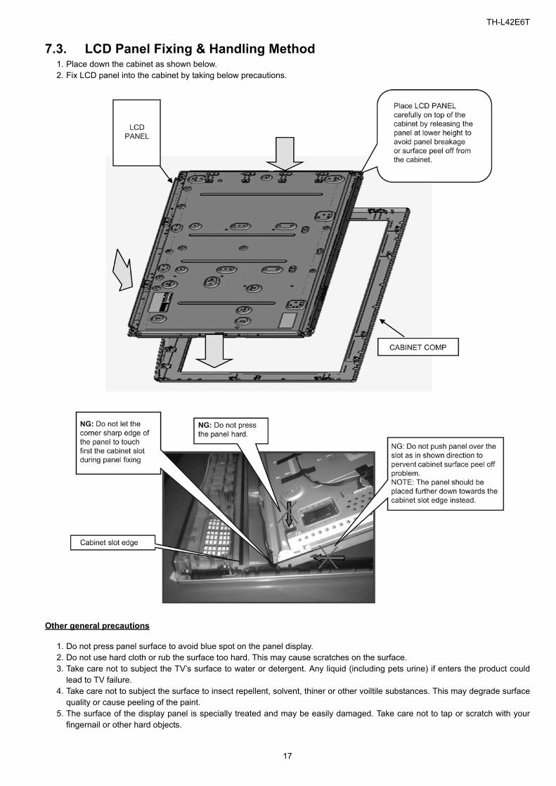
7.3. LCD Panel Fixing & Handling Method1. Place down the cabinet as shown below.2. Fix LCD panel into the cabinet by taking below precautions.
Other general precautions
1. Do not press panel surface to avoid blue spot on the panel display.2. Do not use hard cloth or rub the surface too hard. This may cause scratches on the surface.3. Take care not to subject the TV’s surface to water or detergent. Any liquid (including pets urine) if enters the product could
lead to TV failure.4. Take care not to subject the surface to insect repellent, solvent, thiner or other voiltile substances. This may degrade surface
quality or cause peeling of the paint.5. The surface of the display panel is specially treated and may be easily damaged. Take care not to tap or scratch with your
fingernail or other hard objects.
17

TH-L42E6T
7.4. A_Print Assembly1. Install A_Print. 2. Install SIDE_AV_BRACKET.3. Install BARRIER P-PCB. (Follow step 1 & 2).
No. Item Description QTY UOM
01 TMX5ZE0041 CH_MOUNT_BOSS 2 PC
02 TES5ZA001 GROUND SPRING 2 PC
03 TKP5ZA29402 SIDE AV BRACKET 1 PC
04 TMK4GX156 BARRIER P-PCB 1 PC
05 TMK4GG088 SPONGE(30*30*t40) 1 PC
18

TH-L42E6T
7.5. P_Print Assembly1. Install P_Print.2. Install SPEAKER UNIT.3. Install K-PRINT and LED PANEL.4. Install USB CABLE.
No. Item Description QTY UOM
01 K1HY05YY0051 WIFI USB CABLE 1 PC
02 L0EYAA000023 SPEAKER UNIT R 1 PC
03 L0EYAA000022 SPEAKER UNIT L 1 PC
04 TXJA10SHUA A10-K10 1 PC
05 TKK5ZC50381 LED_PANEL 1 PC
06 TKP5ZA33301 LED_PANEL_CASE 1 PC
07 TWB770 GASKET 1 PC
19

TH-L42E6T
7.6. Screw AssemblyScrewing.
No. Item Description QTY UOM Remarks
01 THEJ036J SCREW(RPM9/RP2/A3/P4/WIFI1/KEY1) 20 PC 6 ± 1 Kgfcm
02 THE4GJ001J SCREW(BTM4) 4 PC 6 ± 1 Kgfcm
03 THEC1509 SCREW(RP3) 3 PC 6 ± 1 Kgfcm
20
TH-L42E6T
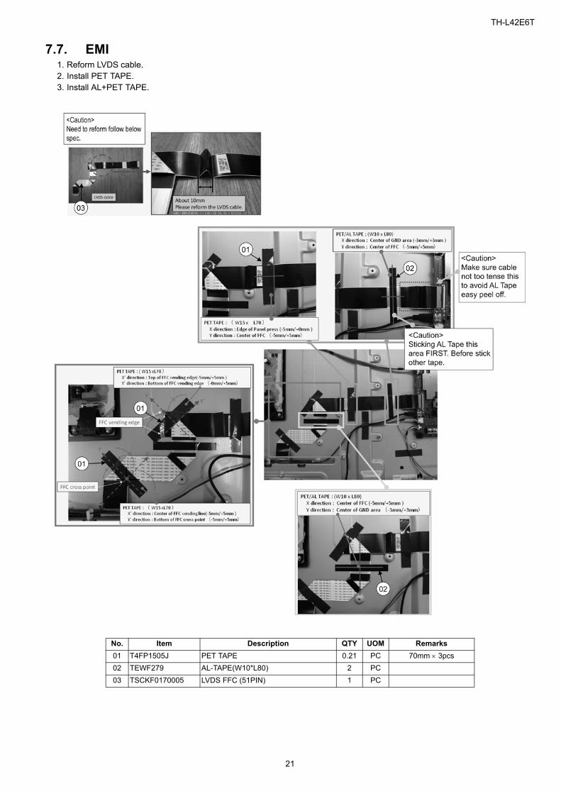
7.7. EMI1. Reform LVDS cable.2. Install PET TAPE.3. Install AL+PET TAPE.
No. Item Description QTY UOM Remarks
01 T4FP1505J PET TAPE 0.21 PC 70mm 3pcs
02 TEWF279 AL-TAPE(W10*L80) 2 PC
03 TSCKF0170005 LVDS FFC (51PIN) 1 PC
21

TH-L42E6T
7.8. Stand Mounting AssemblyAssemble the Stand Mtg Ass’y according to spec.
No. Item Description QTY UOM
01 TQF4GA263 QR_CODE_LABEL 1 PC
02 TPE4GH090 BAG 1 PC
03 TBL5ZA34571 STAND_METAL 1 PC
04 XYN4+F25FJK SCREW 4 PC
05 XSS5+16FJK SCREW 4 PC
22

TH-L42E6T
7.9. Back Cover Assembly 11. Install Back cover.2. Sticking BARRIER_P_PCB_BC.3. Install M6 SPACER.
No. Item Description QTY UOM
01 TKU5ZX08501 BACK COVER 1 PC
02 TMK4GX155 BARRIER BACK COVER 1 PC
03 TKK5ZL50161 M6_SPACER-S 4 PC
23

TH-L42E6T
7.10. Back Cover Assembly 2Fixing Screw for Back cover.
No. Item Description QTY UOM Remarks
01 N5HBZ0000101 WIFI MODULE 1 PC
02 THEC1509 SCREW(BC22/WIFI1/HDMI3) 26 PC Refer to spec.
03 XTV3+8GFJK SCREW(BC3/AV1) 4 PC Refer to spec.
04 THTD030J SCREW(BC3) 3 PC 10 ± 2 Kgfcm
24

TH-L42E6T
7.11. Handling SPEC
■ Moving the LCD module
The module should be handle by two people and hold on that top and bottom long side by both hands without modulewarping. Never handle the module with keeping horizontal position when moving the module in order to avoid internaldamage and deformation. Never drop or hit the module.
■ About the work table
When tightening a screw, retention structures are required not to deform the LCD module.
■ Moving the TV (Case with a stand)
Hold the specified parts as shown to stand the TV up and move it with two people.
25

TH-L42E6T
8 Measurements and Adjustments
8.1. Voltage chart of A-boardSet A-Board to a dummy set and check the satisfaction with the specified voltage as following table.
8.2. Voltage chart of P-boardSet P-Board to a dummy load and check the satisfaction with the specified voltage as following table.
Power Supply Name Measurement Point Specification
PANEL12V TP4000 / 4001 11.50V - 12.50V
SUB5V TP5420 4.95V - 5.40V
SUB3.3V TP5400 3.17V - 3.43V
SUB1.8V TP8714 1.70V - 1.90V Only TNPH1038
SUB1.5V TP8100 1.435V - 1.585V
SUB1.2V TP8101 1.140V - 1.260V
LNB_PWR TP6702 15.30V - 17.10V Only JPN_Model
JP_TU_2.5V TP5705 2.38V - 2.62V
DMD_1.2/1.1V TP5702 1.14V - 1.26V Only JPN_Model
DMD_1.2/1.1V TP5703 1.14V - 1.26V Only DTMB_Model
Output Test Point Step 1 Step 2
24V TP7407 < 1V 24 ± 1.2V
16V TP7410 < 1V 15.7 ± 0.6V
5VS TP7501 5.3 ± 0.2V 5.3 ± 0.2 V
PFC TP7201 or TP7202 < 340V 390V ± 15V *HOT
26

TH-L42E6T
27
9 Block Diagram
9.1. Main Block Diagram
(LE
D:1
TIM
E)
(LED:9 TIMES)
(LED:9 TIMES)
NANDFLASH
DDR3
PO
WE
R_
ON
BL
_S
OS
AVDDH3.3V
WiFi
USB I/F
SOUND_SOS
ACDETECT
USB5V
OUT
LED_R/G
16V
PN
L1
2V
SUB3.3V
C.A.T.S. SENSOR
POWER
POWER SW
BL_SOS
PANEL12VBL_PWM
SU
B_
ON
ETHER I/F
IFD_OUT
SUB3.3V
BL_SOS
ONBOARDTUNER
SUB5V/USB5V
STB3.3V
TMDS DATA
KEY
AC CORD
SUB3.3V
SUB1.2V
P15V
SUB1.5V
HDMI2
USB1
TU_1.8V
AUDIO
DCDC
L/R
LED_R/G
REMOTE RECEIV
STB5V
AUDIO
SUB1.5V
REMOTE IN
ETHERNET
SPEAKER(R)
DCDC
NEUTRAL
TMDS DATA
OVP DET
A20
TU_1.8V
K10
SUB5V
SUB_ON
P2
DCDC
LVDS Tx
SU
B_
ON
P15V
ANALOG-ASIC
SUB1.5
Parallel_TS
SUB1.2V
LIVE
ARC
LED BACK LIGHT
HDMI1
COMPONENT INCVBS IN
ARC_OUT
P4
HDMI3
Y/PB/PR
BL_PWM
SUB_AI_3.3V
JK7101
SPDIF_OUT
DCDC
SUB5V
POWER_ON
DTMB TS I/F
K
DIGITAL
PNL12V
P5
24V
BL
_P
WM
DCDC
AUDIO_OUT
MAIN
P
P15V
PANEL
DMD
DCDC
AV
HDMII/F
SWITCH
DCDC
POWER ON
TV_SOS
GK4
LCD PANEL
STB5V
KEY
AMP
C.A.T.S. SENSOR
SUB3.3V
SUB3.3V
L/R IN
BL_ON
A16
CONTROL PANEL KEY
R
SPEAKER(L)
SUB5V
NAND_I/F
BL
_O
N
A12
PFC
SUB1.5V
DDR_I/F
SUB1.2V
STB3.3V
LED/RM/CATS
SUB_AI_3.3V
SUB_ON
REG
A10
L
LCD DRIVER
INPUTFILTER
LLCCONVERTER
5VS
A
P15V
TMDS DATA
SUB1.2V
KE
Y
USB2
BL_ON
GK
A02
STB3.3V
HDMI3.3V
STB3.3V
Paragon
RF IN
(LE
D:1
TIM
E)
(LED:8 TIMES)
(LED:9 TIMES)
TH-L42E6T
28
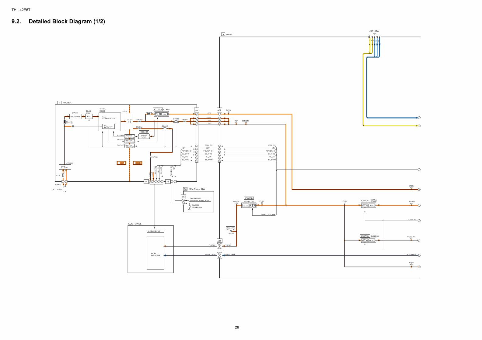
9.2. Detailed Block Diagram (1/2)
NO
HO
LD
ER
COLDHOT
BL_ON
BL_SOS
BL_PWM
KE
Y
PO
WE
R_
ON
POWER_ON
BL_ON
POWER_ON
BL_PWMB
L_S
OS
KEY
BL_O
N
SUB_ON
KEY
BL_P
WM
BL_SOS
PA7401
F7101
SW2857
D7401,2
D7408,9 P15VPA7402
PNL12V P15V P15V
5.8VS
**
P15V
PA7406
SUB3.3V
SUB5V
STB5V
DCDCIN
TP0001
12
5VSD7106
Y
10
+5V
SUB_ON
Q7403
L
13
BL_ON11
+24V
IC7201,T7201,Q7201
40
CF7102
IC7401
3
9
KEY
+5V
+24V
8
8
JK3101A
LINEFILTER
USB5V
LVDS_DATA
STB5VIC7301,Q7301,Q7302
11
IC5300
PHOTOCOUPLER
1
ACDETECT
PNL12V
11
BL_PWM
2
610
P
PHOTOCOUPLER
A16
2
P4
SW2851-2855
KEY,Power SW
2
IC87042
PNL12V
+16V2
P2
PC7302
3
8
A
DCDCEN2
3
PFC
LVDS_DATA
PANEL12VCONTROL PANEL KEY
6
+16V
IC8705 SUB3.3V
9
12
P5
PR
3
POWER ON
4
R
AV
Q7402
POWER
T7301
+3.3V
LF7103-5
AC CORD
SUB5V
1
POWER SW
ERRORDETCT
10
PHOTOCOUPLER
1
1
GK4
1
BL_SOS
PB
5
PANEL_VCC_ON
7
+16V
PC7301
+12V
LVDS_DATA
MAIN
2
A02
4
LCDDRIVER
7
1
IC7503
3
4
CF7101
LED DRIVE
LLCCONVERTER
11
RECTIFIER
PC7303
8
4
JK7101
LCD PANEL
GK 5
PNL12V
COLDHOT

TH-L42E6T
29
9.3. Detailed Block Diagram (2/2)
(LE
D:1
TIM
E)
(LE
D:9
TIM
ES
)
(LE
D:9
TIM
ES
)
VC
C
GN
D
OU
T
GR
R_LED_ON
BL_O
N RE
MO
TE
REMOTE
PW
M_E
N
KE
Y
PO
WE
R_O
N
AI_SENSOR
G_LE
D_O
N
BL_S
OS
SU
B_O
N
AI_
SE
NS
OR
G_LED_ON
R_LE
D_O
N
TV
_S
OS
P_P
WM
A
X8300
P15V
SN2800
D5178
SUB3.3V
SUB1.5V
SUB5VX6800
D5191
STB5V
SUB1.2V
RM2800
123
D5179
SUB3.3V
D5173
SUB3.3V
D5172
D2802
D5188
P15V
SUB5V
STB3.3V
SUB3.3V
AVDDH3.3V
STB5V
D5187
X6750
1
FE_XRST
KE
Y
27MHz
ON BOARD TUNER
RM
_IN
+1.2V
IC6800
HD
MI_
5V
_D
ET
3
IIC_2
HDMI1
8
SO
S
DMD_1.2V
OVP_DET
SO
UN
D_S
OS
_D
ET
IC8101
PW
M_E
N
COMPONENT INCVBS IN
IFD
1
ParagonResetCircuit
AGC
PO
WE
R_O
N
STB3.3V
PA
NE
L_V
CC
_O
N
R(+
)
3
IC8100
IC8706
A20
REMOTERECEIVER
US
B_I/F
FE_XRST
DD
R_I/F
+5V
IIC_2
TU
_1.8
V
FE
_X
RS
T
DD
C3
DTMB
G_LE
D_O
N
ST
B3.3
V
IC5720
CE
C
IFD
1
A
AG
C1
POWER LED
K10
41MHz
IC6705
4
+1.5V
15V
UART
IC8900
VB
US
1
11
JK8601
TU
_3.3
V
BL_PWM
TV
_S
OS
XR
ST
HD
MI3
.3V
1.2V
WiFi
PWM_A_OUT
AGC1
US
B_I/F
1
R_LE
D_O
N
DD
C IIC
3
NAND_IF
OVP
DIGITALAUDIO OUT
HD
MI_
CE
C
TV_SOS
A
POWER LED/REMOTE RECEIVER/C.A.T.S. SENSOR
SUB_ON
CA
TS
_E
YE
DDR3
USB1
IC5000
BL_S
OS
2
STB3.3V 5
6
DCDC_CTL
4
9
TV_SOS
IIC_2
SPEAKER_R
R(-
)
6
SU
B3.3
V
ANALOG-ASIC
AUDIO AMP
HDMI3
3
IC8201
SUB5V7
SD
IN
PO
WE
R_D
ET
DCDCEN2
L(+
)
4
TM
DS
DA
TA
/C
LO
CK
IC8
60
5
IFD
2
PA
NE
L_V
CC
_O
N
DEMODULATOR
D3201
AG
C2
A10
VB
US
2
PWM_A_IN
IIC_0
A12
Rx1
IIC_0
STB5V
DD
C1
FORFACTORYUSEETHERNET
R_LED_ON
2
SUB3.3V
JK8602
4
LATCHSUB_ON
IC4900
L(-
)
K
MAIN
5
SPEAKER_L
G_LED_ON
AI_SENSOR
IC8
60
2
JK8650A
10
Paragon
PWM_POWON
+1.8V
DD
C IIC
1
IC5704
US
B_I/F
SUB_AI_3.3V
DCDCEN
C.A.T.S.SENSOR
IIC_2
1
SUB1.2V
HD
MI_
5V
_D
ET
1
PA
NE
L_P
WM
VB
US
3
TS I/F
PWM_EN
JK4701 JK4703
+3.3V
LV
DS
_T
x
+5V
ET
HE
R_I/F
7
3
CN0100
MAIN
P15V
LVDS_DATA
Rx3
L/R IN
UART
REMOTE
IC8000
AU
DIO
_O
UT
TM
DS
DA
TA
/C
LO
CK
IEC
_O
UT
IIC_0IIC_2UART
7
BL_O
N
USB2
SU
B_O
N
IC8
60
3
IC8200
P_PWMA
NANDFLASH
SU
B1.5
V
HD
MI_
CE
C
5
RF IN
24MHz
JK6750
HD
MI_
CE
C
AR
C_O
UT
DD
C IIC
0D
DC
2
TM
DS
DA
TA
/C
LO
CK
Rx2
+5V
HD
MI_
5V
_D
ET
2
HDMI2JK4702
(LE
D:1
TIM
E)
(LE
D:9
TIM
ES
)
(LE
D:8
TIM
ES
)

TH-L42E6T
10 Wiring Connection Diagram
10.1. Wire Dressing1. Install wire.2. Install PET TAPE.3. Install AL+PET TAPE.
No. Item Description QTY UOM Remarks
01 TXJA02SHUA A02-P2 1 PC
02 T4FP1505J PET TAPE 0.28 PC 70mm 4pcs
03 TXJA12SHUA A12-SP WF 1 PC
30

TH-L42E6T
11 Schematic Diagram
Model No. : TH-L42E6T A-Board (1/13)
31

Model No. : TH-L42E6T A-Board (2/13)

Model No. : TH-L42E6T A-Board (3/13)

Model No. : TH-L42E6T A-Board (4/13)

Model No. : TH-L42E6T A-Board (5/13)

Model No. : TH-L42E6T A-Board (6/13)

Model No. : TH-L42E6T A-Board (7/13)

Model No. : TH-L42E6T A-Board (8/13)

Model No. : TH-L42E6T A-Board (9/13)

Model No. : TH-L42E6T A-Board (10/13)

Model No. : TH-L42E6T A-Board (11/13)

Model No. : TH-L42E6T A-Board (12/13)

Model No. : TH-L42E6T A-Board (13/13)
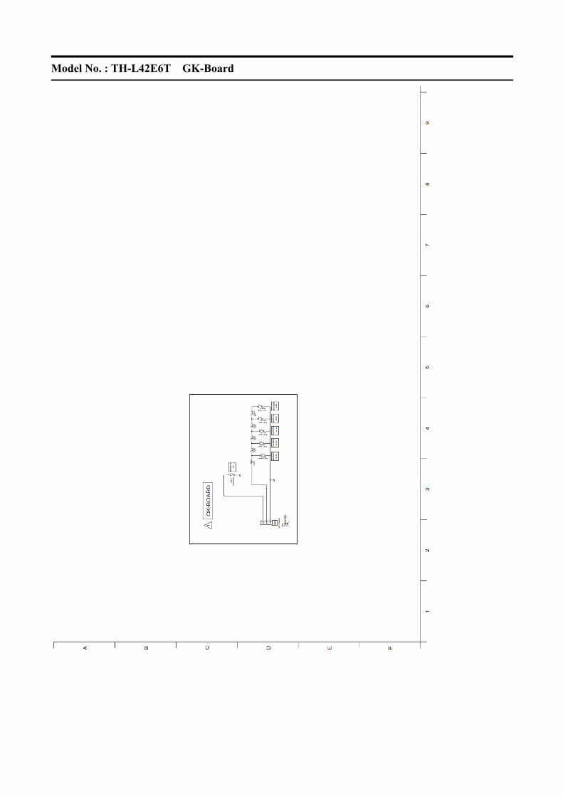
Model No. : TH-L42E6T GK-Board
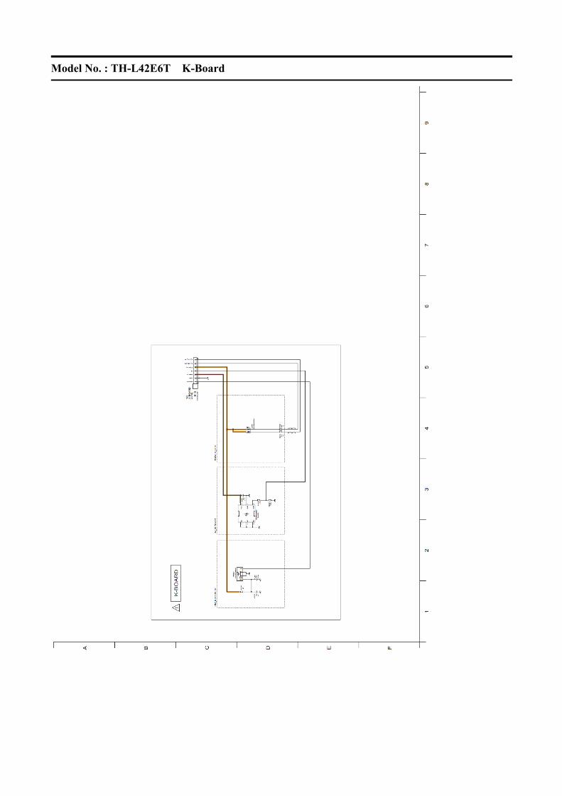
Model No. : TH-L42E6T K-Board
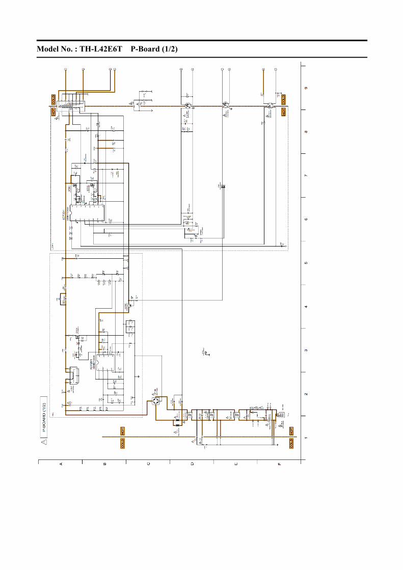
Model No. : TH-L42E6T P-Board (1/2)

Model No. : TH-L42E6T P-Board (2/2)

TH-L42E6T
12 Printed Circuit Board
Model No. : TH-L42E6T A-Board (Top Component Side)
48

Model No. : TH-L42E6T A-Board (Bottom Component Side)

Model No. : TH-L42E6T GK-Board

Model No. : TH-L42E6T K-Board

Model No. : TH-L42E6T P-Board (Top Component Side)

Model No. : TH-L42E6T P-Board (Bottom Component Side)

TH-L42E6T
13 Exploded View and Replacement Parts List
Model No. : TH-L42E6T Parts Location
54

Model No. : TH-L42E6T Packing Exploded View

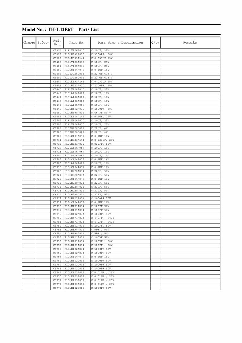
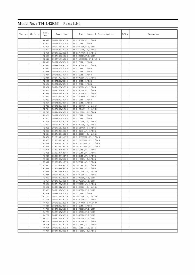
Model No. : TH-L42E6T Parts List
Change SafetyRef. No.
Part No. Part Name & Description Q'ty Remarks
CAPACITORS
C2000 F1G1A105A047 C 1UF 10V
C2009 F1G1H1020008 C 1000PF 50V
C2012 F1G1E103A059 C 0.01UF 25V
C2014 F1K1V106A010 C 10UF, 25V
C2017 F1G1H1020008 C 1000PF 50V
C2023 F1G1C104A077 C 0.1UF 16V
C2801 F1G1C1030008 C 0.01UF 16V
C2804 F1H1C104A178 C 0.1UF, 16V
C2807 F1J1A106A043 C 10UF, 10V
C3000 F1G1C104A077 C 0.1UF 16V
C3009 F1G1H100A834 C 10PF 50V
C3010 F1G1H100A834 C 10PF 50V
C3011 F1G1H100A834 C 10PF 50V
C3012 F1G1H152A830 C 1500PF, 50V
C3013 F1G1C1030008 C 0.01UF 16V
C3014 F1G1C1030008 C 0.01UF 16V
C3015 F1G1C1030008 C 0.01UF 16V
C3016 F1G1C1030008 C 0.01UF 16V
C3036 F1G1A105A047 C 1UF 10V
C3037 F1G1A105A047 C 1UF 10V
C3042 F1G1A473A069 C0.047UF, 10V
C3180 F1G1C104A077 C 0.1UF 16V
C3181 F1G1A105A047 C 1UF 10V
C3319 F1H1A225A102 C 2.2UF , 10V
C4000 F1K1E106A134 C 10UF, 25V
C4001 F1K1E106A134 C 10UF, 25V
C4002 F1H1H103B047 C 0.01UF, 50V
C4003 F1H1H103B047 C 0.01UF, 50V
C4701 F1G1A105A047 C 1UF 10V
C4902 F1J1E105A287 C 1UF, 25V
C4904 F1J1E105A287 C 1UF, 25V
C4907 F1K1V106A010 C 10UF, 25V
C4908 F1J1E105A287 C 1UF, 25V
C4910 F1H1E104A161 C 0.1UF, 25V
C4911 F1J1E105A287 C 1UF, 25V
C4916 F1H1E104A161 C 0.1UF, 25V
C4920 F1H1C105A167 C 1UF, 10V
C4924 F1H1E104A161 C 0.1UF, 25V
C4933 F1H1E104A161 C 0.1UF, 25V
C4937 F1J1E224A272 C 0.22UF, 25V
C4938 F1J1E224A272 C 0.22UF, 25V
C5000 F1G1A105A047 C 1UF 10V
C5002 F1G1A105A047 C 1UF 10V
C5004 F1G1A105A047 C 1UF 10V
C5006 F1J1E105A287 C 1UF, 25V
C5012 F1G1A105A047 C 1UF 10V
C5020 F1G1C104A077 C 0.1UF 16V
C5021 F1G1A105A047 C 1UF 10V
C5022 F1G1A105A047 C 1UF 10V
C5026 F1H1E105A153 C 1UF, 16V
C5171 F1G1C1030008 C 0.01UF 16V
C5181 F1G1H332A830 C 3300PF, 50V
C5182 F1G1C104A077 C 0.1UF 16V
C5183 F1G1H1020008 C 1000PF 50V
C5244 F1G1H1020008 C 1000PF 50V
C5318 F1G1C104A077 C 0.1UF 16V
C5319 F1K1V106A010 C 10UF, 25V
C5320 F1K1V106A010 C 10UF, 25V
C5321 F1K1V106A010 C 10UF, 25V
C5322 F1K1V106A010 C 10UF, 25V
C5323 F1K1V106A010 C 10UF, 25V
Model No. : TH-L42E6T Parts List
Change SafetyRef. No.
Part No. Part Name & Description Q'ty Remarks
C5324 F1K1V106A010 C 10UF, 25V
C5328 F1G1H332A830 C 3300PF, 50V
C5329 F1G1E333A144 C 0.033UF 25V
C5400 F1K1V106A010 C 10UF, 25V
C5401 F1K1V106A010 C 10UF, 25V
C5402 F1G1C104A077 C 0.1UF 16V
C5403 F1J0J2260004 C 22 UF 6.3 V
C5404 F1J0J2260004 C 22 UF 6.3 V
C5407 F1G1E333A144 C 0.033UF 25V
C5408 F1G1H222A830 C 2200PF, 50V
C5440 F1K1V106A010 C 10UF, 25V
C5443 F1J1A106A087 C 10UF, 10V
C5444 F1J1A106A087 C 10UF, 10V
C5445 F1J1A106A087 C 10UF, 10V
C5446 F1J1A106A087 C 10UF, 10V
C5449 F1G1H152A830 C 1500PF, 50V
C5450 F1G1H680A834 C 68 PF 50 V
C5453 F1G1E104A145 C 0.1UF, 25V
C5705 F1K1V106A010 C 10UF, 25V
C5706 F1K1V106A010 C 10UF, 25V
C5707 F1J0G2260001 C 22UF, 4V
C5708 F1J0G2260001 C 22UF, 4V
C5709 F1G1C104A077 C 0.1UF 16V
C5711 F1G1E333A144 C 0.033UF, 25V
C5713 F1G1H821A830 C 820PF, 50V
C5717 F1J1A106A087 C 10UF, 10V
C5718 F1J1A106A087 C 10UF, 10V
C6704 F1J1A106A087 C 10UF, 10V
C6707 F1G1C104A077 C 0.1UF 16V
C6708 F1J1A106A087 C 10UF, 10V
C6710 F1G1C104A077 C 0.1UF 16V
C6720 F1G1H220A834 C 22PF, 50V
C6721 F1G1H220A834 C 22PF, 50V
C6722 F1G1C104A077 C 0.1UF 16V
C6723 F1G1H220A834 C 22PF, 50V
C6724 F1G1H220A834 C 22PF, 50V
C6726 F1G1H220A834 C 22PF, 50V
C6727 F1G1H220A834 C 22PF, 50V
C6728 F1G1H102A834 C 1000PF 50V
C6732 F1G1C104A077 C 0.1UF 16V
C6736 F1G1H101A834 C 100PF 50V
C6737 F1G1H101A834 C 100PF 50V
C6745 F1G1H102A834 C 1000PF 50V
C6750 F1G1H471A834 C 470PF , 240V
C6751 F1G1H471A834 C 470PF , 240V
C6752 F1G1H101A834 C 100PF, 50V
C6753 F1G1H5R0A831 C 5PF , 50V
C6754 F1G1H5R0A831 C 5PF , 50V
C6757 F1G1H101A834 C 100PF 50V
C6758 F1G1H181A834 C 180PF , 50V
C6759 F1G1H181A834 C 180PF , 50V
C6760 F1G1H102A834 C 1000PF 50V
C6762 F1G1H102A834 C 1000PF 50V
C6764 F1G1C104A077 C 0.1UF 16V
C6766 F1G1H1020008 C 1000PF 50V
C6767 F1G1H1020008 C 1000PF 50V
C6768 F1G1H1020008 C 1000PF 50V
C6769 F1G1E103A059 C 0.01UF , 25V
C6770 F1G1E103A059 C 0.01UF , 25V
C6771 F1G1E103A059 C 0.01UF , 25V
C6772 F1G1E103A059 C 0.01UF , 25V
C6773 F1G1H1020008 C 1000PF 50V

Model No. : TH-L42E6T Parts List
Change SafetyRef. No.
Part No. Part Name & Description Q'ty Remarks
C6774 F1G1C104A077 C 0.1UF 16V
C6775 F1G1C104A077 C 0.1UF 16V
C6777 F1G0J105A049 C 1UF , 6.3V
C6804 F1G1C104A077 C 0.1UF 16V
C6805 F1J1A106A087 C 10UF, 10V
C6806 F1J1A106A087 C 10UF, 10V
C6809 F1G1C104A077 C 0.1UF 16V
C6820 F1G1C104A077 C 0.1UF 16V
C6822 F1G1C104A077 C 0.1UF 16V
C6830 F1G1C104A077 C 0.1UF 16V
C6832 F1J1A106A087 C 10UF, 10V
C6838 F1G1C104A077 C 0.1UF 16V
C6840 F1G1C104A077 C 0.1UF 16V
C6844 F1G1C104A077 C 0.1UF 16V
C6847 F1G1H8R0A833 C 8PF, 50V
C6848 F1G1H8R0A833 C 8PF, 50V
C6864 F1G1C104A077 C 0.1UF 16V
C6872 F1G1C104A077 C 0.1UF 16V
C6873 F1G1C104A077 C 0.1UF 16V
C7102 F1AAF471A019 C 470PF , 240V
C7103 F1AAF471A019 C 470PF , 240V
C7104 F0CAF2240010 C 0.22UF, 240V
C7105 F0CAF2240010 C 0.22UF, 240V
C7201 F1J1H102A909 C 1000pF, 50V
C7202 F1J1H222A911 C 2200pF, 50V
C7203 F1H1H104B047 C 0.1UF, 50V
C7204 F1H1H104B047 C 0.1UF, 50V
C7205 F1J1H102A909 C 1000pF, 50V
C7206 F1J1E475A257 C 4.7UF, 25V
C7207 F1A3A221A060 C 220PF 1KV
C7208 F1J1H104A902 C 0.1UF, 50V
C7209 ECWFD2W155KC C 1.5UF, 240V
C7213 F2A2W6800013 C 68UF, 450V
C7214 F1J1H103A900 C 0.01UF, 50V
C7220 F1J1H472A900 C 4700PF, 50V
C7302 F1J1H473A900 C 0.047UF, 16V
C7303 F1J1H104A902 C 0.1UF, 50V
C7304 F1A3A221A060 C 220PF 1KV
C7305 F1J1H104A902 C 0.1UF, 50V
C7306 F1J1H104A902 C 0.1UF, 50V
C7307 F1J1H101A906 C 100PF, 50V
C7310 F2A1E4710124 C 470UF, 25V
C7311 F1J1E105A287 C 1UF, 25V
C7312 F1H1C474A178 C 0.47UF, 16V
C7313 F1J1H102A909 C 1000pF, 50V
C7315 F1A3A221A060 C 220PF 1KV
C7316 F1A3A221A060 C 220PF 1KV
C7317 ECWH8223HAC C 0.022UF, Z, 800V
C7318 F1AAF471A019 C 470PF , 240V
C7416 F1J1C475A225 C 4.7UF, 10V
C7417 F1J1E474A272 C 0.47UF, 25V
C7418 F1H1H104B047 C 0.1UF, 50V
C7421 F1H1H104B047 C 0.1UF, 50V
C7422 F2A1V2710019 C 270UF, 35V
C7423 F2A1E222B927 C 2200UF, 25V
C7429 F1K1V106A010 C 10UF, 25V
C7434 F1J1C475A225 C 4.7UF, 10V
C7520 F1J1E105A287 C 1UF, 25V
C7521 F1J1E105A287 C 1UF, 25V
C7522 F1K1V106A010 C 10UF, 25V
C7523 F1K1V106A010 C 10UF, 25V
C7524 F1J1H472A900 C 4700PF, 50V

Model No. : TH-L42E6T Parts List
Change SafetyRef. No.
Part No. Part Name & Description Q'ty Remarks
C7525 F1J1H223A900 C 0.022UF, 50V
C7526 F1K1V106A010 C 10UF, 25V
C7527 F1K1V106A010 C 10UF, 25V
C7529 F1J1H103A900 C 0.01UF, 50V
C8002 F1G1C104A077 C 0.1UF 16V
C8007 F1J0G2260001 C 22 UF 4 V
C8008 F1G1C104A077 C 0.1UF 16V
C8012 F1G1C104A077 C 0.1UF 16V
C8013 F1G1C104A077 C 0.1UF 16V
C8014 F1J1A106A087 C 10UF, 10V
C8015 F1G1A105A047 C 1UF 10V
C8016 F1G1C104A077 C 0.1UF 16V
C8018 F1G1C104A077 C 0.1UF 16V
C8019 F1J0G2260001 C 22 UF 4 V
C8021 F1G1A105A047 C 1UF 10V
C8022 F1G1C104A077 C 0.1UF 16V
C8023 F1G1C104A077 C 0.1UF 16V
C8024 F1G1C104A077 C 0.1UF 16V
C8025 F1G1C104A077 C 0.1UF 16V
C8027 F1G1C104A077 C 0.1UF 16V
C8030 F1G1C104A077 C 0.1UF 16V
C8031 F1G1C104A077 C 0.1UF 16V
C8032 F1G1A105A047 C 1UF 10V
C8033 F1H0J4750004 C 4.7UF, 16V
C8034 F1G1C104A077 C 0.1UF 16V
C8036 F1G1C104A077 C 0.1UF 16V
C8038 F1G1C104A077 C 0.1UF 16V
C8039 F1G1A105A047 C 1UF 10V
C8040 F1G1A105A047 C 1UF 10V
C8041 F1J0G2260001 C 22 UF 4 V
C8042 F1G1C104A077 C 0.1UF 16V
C8044 F1G1C104A077 C 0.1UF 16V
C8046 F1G1C104A077 C 0.1UF 16V
C8048 F1J0G2260001 C 22 UF 4 V
C8049 F1G1C104A077 C 0.1UF 16V
C8050 F1G1C104A077 C 0.1UF 16V
C8051 F1G1C104A077 C 0.1UF 16V
C8052 F1J0G2260001 C 22 UF 4 V
C8100 F1K1V106A010 C 10UF, 25V
C8102 F1G1C104A077 C 0.1UF 16V
C8103 F1G1C473A048 C 0.047UF, 16V
C8105 F1G1E332A144 C 3300PF, 25V
C8107 F1J0G2260001 C 22 UF 4 V
C8108 F1J0G2260001 C 22 UF 4 V
C8109 F1H1E105A153 C 1UF, 16V
C8110 F1G1C183A146 C 0.018UF, 16V
C8111 F1G1C104A077 C 0.1UF 16V
C8112 F1K1V106A010 C 10UF, 25V
C8114 F1J0G2260001 C 22 UF 4 V
C8116 F1J0G2260001 C 22 UF 4 V
C8117 F1H1E104A161 C 0.1UF, 25V
C8200 F1G1C104A077 C 0.1UF 16V
C8201 F1G1C104A077 C 0.1UF 16V
C8202 F1G1C104A077 C 0.1UF 16V
C8203 F1G1C104A077 C 0.1UF 16V
C8204 F1G1C104A077 C 0.1UF 16V
C8205 F1G1C104A077 C 0.1UF 16V
C8206 F1G1C104A077 C 0.1UF 16V
C8207 F1J1A106A087 C 10UF, 10V
C8208 F1G1C104A077 C 0.1UF 16V
C8213 F1G1C104A077 C 0.1UF 16V
C8215 F1G1C104A077 C 0.1UF 16V

Model No. : TH-L42E6T Parts List
Change SafetyRef. No.
Part No. Part Name & Description Q'ty Remarks
C8216 F1J1A106A087 C 10UF, 10V
C8217 F1G1C104A077 C 0.1UF 16V
C8218 F1G1C104A077 C 0.1UF 16V
C8219 F1G1C104A077 C 0.1UF 16V
C8220 F1G1C104A077 C 0.1UF 16V
C8222 F1G1C104A077 C 0.1UF 16V
C8225 F1G1C104A077 C 0.1UF 16V
C8230 F1G1C104A077 C 0.1UF 16V
C8232 F1G1C104A077 C 0.1UF 16V
C8255 F1J0G2260001 C 22 UF 4 V
C8300 F1G1H8R0A831 C 8 PF, 50V
C8301 F1G1H8R0A831 C 8 PF, 50V
C8601 F1G1C1030008 C 0.01UF 16V
C8602 F1G1C1030008 C 0.01UF 16V
C8613 F1J1A106A087 C 10UF, 10V
C8615 F1G1C104A077 C 0.1UF 16V
C8642 F1J1A106A087 C 10UF, 10V
C8643 F1G1C104A077 C 0.1UF 16V
C8680 EEEHB0J221UP E 220UF, 6.3V
C8681 EEEHB0J221UP E 220UF, 6.3V
C8682 F1J1A106A087 C 10UF, 10V
C8683 F1G1C104A077 C 0.1UF 16V
C8687 F1J1A106A087 C 10UF, 10V
C8688 F1G1C104A077 C 0.1UF 16V
C8689 F1J1A106A087 C 10UF, 10V
C8690 F1G1C104A077 C 0.1UF 16V
C8692 F1J1A106A087 C 10UF, 10V
C8693 F1G1C104A077 C 0.1UF 16V
C8760 F1G1C104A077 C 0.1UF 16V
C8764 F1G1A105A047 C 1UF 10V
C8765 F1H0J4750004 C 4.7UF, 16V
C8850 F1H0J4750004 C 4.7UF, 16V
C8851 F1H0J4750004 C 4.7UF, 16V
C8902 F1G1C104A077 C 0.1UF 16V
C8903 F1G1C104A077 C 0.1UF 16V
DIODES
D2802 B3AGB0000060 LED
D3021 DZ2J140M0L DIODE
D3022 DZ2J140M0L DIODE
D3023 DZ2J140M0L DIODE
D3024 DZ2J140M0L DIODE
D3025 DZ2J140M0L DIODE
D3026 DZ2J140M0L DIODE
D3201 K7AAAY000016 DIODE
D5172 DZ2J220M0L DIODE
D5173 DA2J10100L DIODE
D5178 DZ2J068M0L DIODE
D5179 B0ADCK000001 DIODE
D5180 DZ2J033M0L DIODE
D5187 DZ2J047M0L DIODE
D5188 B0ADCK000001 DIODE
D5191 B0ADCK000001 DIODE
D5208 B0ADCK000001 DIODE
D6750 J0ZZB0000175 DIODE
D6751 B0ZBZ0000203 DIODE
D7101 ERZE08C621CD SURGE ABSORBER
D7104 B0EAKR000022 DIODE
D7105 B0EAKR000022 DIODE
D7106 B0EBNT000028 DIODE
D7211 B0JCME000093 DIODE
D7215 B0HAPR000013 DIODE
D7221 B0JCDE000006 DIODE

Model No. : TH-L42E6T Parts List
Change SafetyRef. No.
Part No. Part Name & Description Q'ty Remarks
D7301 DZ2J039M0L DIODE
D7302 B0HAGQ000001 DIODE
D7303 DZ2J039M0L DIODE
D7304 DA2JF2300L DIODE
D7305 B0ADCK000001 DIODE
D7306 B0BC027A0336 DIODE
D7307 B0BC027A0336 DIODE
D7308 B0BC027A0336 DIODE
D7309 B0JCME000093 DIODE
D7310 B0JCME000093 DIODE
D7311 B0BC027A0336 DIODE
D7401 B0JDRK000003 DIODE
D7402 B0JDRK000003 DIODE
D7404 DA2J10100L DIODE
D7405 DA2J10100L DIODE
D7408 B0JDSG000010 DIODE
D7409 B0JDSG000010 DIODE
D7411 DA2J10100L DIODE
D7502 DB2J41100L DIODE
D8716 B0ACGM000001 DIODEINTEGRATED CIRCUITS
IC4900 C1AB00003984 IC
IC5000 AN34043AAVF IC
IC5203 C0EBD0000300 IC
IC5300 C0DBAYY01648 IC
IC5702 C0DBAYY01656 IC
IC5704 C0DBEYY00102 IC
IC6750 C1AB00004053 IC
IC6800 C1AB00004028 IC
IC7201 C0DBBYY00058 IC
IC7301 C0DBAYY01329 IC
IC7401 C0DBZYY00614 IC
IC7503 C0DBAYY01599 IC
IC8000 C1AB00004073 IC
IC8100 C0DBAYY01644 IC
IC8101 C0DBAYY01692 IC
IC8200 C3ABUY000020 IC
IC8201 C3ABUY000020 IC
IC8602 C0DBZYY00541 IC
IC8603 C0DBZYY00541 IC
IC8605 C0DBZYY00541 IC
IC8704 C0DBAYY01647 IC
IC8705 C0DBAYY01299 IC
IC8706 C0DBGYY01682 IC
IC8900 TVRT271 ROM IC (C3FBVY000034)
COILS
L2000 J0JHC0000042 COIL
L4006 J0ZZB0000147 COIL
L4007 J0ZZB0000147 COIL
L4008 J0ZZB0000147 COIL
L4009 J0ZZB0000147 COIL
L4010 J0ZZB0000147 COIL
L4011 J0ZZB0000147 COIL
L4901 G1C220MA0533 INDUCTOR
L4902 G1C220MA0533 INDUCTOR
L4903 G1C220MA0533 INDUCTOR
L4904 G1C220MA0533 INDUCTOR
L5201 J0JYC0000464 BEAD CORE
L5300 G1C220MA0445 INDUCTOR
L5400 G1C4R7ZA0311 INDUCTOR
L5440 G1C4R7MA0445 INDUCTOR
L5700 G1C2R2MA0464 INDUCTOR

Model No. : TH-L42E6T Parts List
Change SafetyRef. No.
Part No. Part Name & Description Q'ty Remarks
L5701 J0JYC0000464 BEAD CORE
L6704 J0JYC0000464 BEAD CORE
L6706 J0JYC0000464 BEAD CORE
L6761 J0JYC0000464 BEAD CORE
L6762 J0JYC0000464 BEAD CORE
L6763 G1CR27JA0097 COIL
L6765 G1C82NJ00010 COIL
L6772 G1CR27JA0097 COIL
L6773 G1CR27JA0097 COIL
L6774 G1CR27JA0097 COIL
L6775 G1CR22JA0097 COIL
L6776 G1CR27JA0097 COIL
L6777 G1CR22JA0097 COIL
L6778 G1CR22JA0097 COIL
L6779 G1CR22JA0097 COIL
L6800 J0JYC0000464 BEAD CORE
L6801 J0JYC0000464 BEAD CORE
L6802 J0JYC0000464 BEAD CORE
L7202 J0JKB0000034 EMI FILTER
L7207 J0JHC0000075 BEAD COIL
L7502 G0C270MA0049 INDUCTOR
L8100 G1C3R3MA0464 INDUCTOR
L8101 G1C1R5ZA0311 COIL
L8605 J0JYC0000464 BEAD CORE
L8617 J0JYC0000464 BEAD CORE
L8618 J0JYC0000464 BEAD CORE
TRANSISTORS
Q2012 B1ABCE000015 TRANSISTOR
Q2013 B1ABCE000015 TRANSISTOR
Q4700 B1ABCF000231 TRANSISTOR
Q4701 B1ABCF000231 TRANSISTOR
Q4750 B1ABCF000231 TRANSISTOR
Q5140 B1ABCE000015 TRANSISTOR
Q5141 B1ABCE000015 TRANSISTOR
Q5142 B1ADCE000022 TRANSISTOR
Q5143 B1ABCE000015 TRANSISTOR
Q7201 B1CERR000057 TRANSISTOR
Q7202 B1ADCE000022 TRANSISTOR
Q7301 B1CFRR000016 TRANSISTOR
Q7302 B1CFRR000016 TRANSISTOR
Q7303 B1ADCE000022 TRANSISTOR
Q7401 B1ABCF000231 TRANSISTOR
Q7402 B1CHRE000015 TRANSISTOR
Q7403 B1CHRE000015 TRANSISTOR
Q7407 B1CBGD000001 TRANSISTOR
Q7501 B1ABGE000015 TRANSISTOR
Q8750 B1ABBE000003 TRANSISTOR
Q8751 B1ABBE000003 TRANSISTORRESISTORS
R0900 D0GA473JA039 M 47KOHM J. 1/10W
R0901 D0GA332JA023 M 3.3KOHM, J,1/16W
R0902 D0GA332JA023 M 3.3KOHM, J,1/16W
R0903 D0GA332JA023 M 3.3KOHM, J,1/16W
R0904 D0GA332JA023 M 3.3KOHM, J,1/16W
R0905 D0GA330JA023 M 33 OHM, J,1/16W
R0906 D0GA330JA023 M 33 OHM, J,1/16W
R0908 D0GA272JA023 M 2.7KOHM, J.1/16W
R0911 D0GA272JA023 M 2.7KOHM, J.1/16W
R0926 D0GA473JA039 M 47KOHM J. 1/10W
R0927 D0GA473JA039 M 47KOHM J. 1/10W
R0928 D0GA332JA023 M 3.3KOHM, J,1/16W
R0929 D0GA332JA023 M 3.3KOHM, J,1/16W
Model No. : TH-L42E6T Parts List
Change SafetyRef. No.
Part No. Part Name & Description Q'ty Remarks
R0935 D0GA473JA039 M 47KOHM J. 1/10W
R2003 D0GAR00J0005 M 0 OHM, 1/16W
R2004 D0GA103JA039 M 10KOHM,F,1/16W
R2007 D0GA680JA023 M 68 OHM, J,1/16W
R2008 D0GA153JA023 M 15K OHM J 1/16W
R2009 D1BA1002A023 M 10KOHM,F,1/16W
R2010 D1BA7151A023 M 7.15KOHM, F 1/16 W
R2011 D0GAR00J0005 M 0 OHM, 1/16W
R2012 D0GA473JA039 M 47KOHM J. 1/10W
R2013 D0GAR00J0005 M 0 OHM, 1/16W
R2016 D0GAR00J0005 M 0 OHM, 1/16W
R2034 D0GAR00J0005 M 0 OHM, 1/16W
R2040 D0GA473JA039 M 47KOHM J. 1/10W
R2051 D0GAR00J0005 M 0 OHM, 1/16W
R2056 D0GAR00J0005 M 0 OHM, 1/16W
R2058 D0GA473JA039 M 47KOHM J. 1/10W
R2059 D0GA103JA039 M 47KOHM J. 1/10W
R2060 D0GA473JA039 M 47KOHM J. 1/10W
R2061 D0GA223JA023 M 22K OHM J 1/16W
R2062 D0GAR00J0005 M 0 OHM, 1/16W
R2067 D0GAR00J0005 M 0 OHM, 1/16W
R2713 D0GA222JA023 M 2.2KOHM, J,1/16W
R2714 D0GA222JA023 M 2.2KOHM, J,1/16W
R2715 D0GA680JA023 M 68 OHM, J,1/16W
R2802 D0GAR00J0005 M 0 OHM, 1/16W
R2807 D0GAR00J0005 M 0 OHM, 1/16W
R2820 D0GA470JA023 M 47 OHM, J,1/16W
R2821 D0GA473JA023 M 47KOHM, J,1/16W
R2822 D0GA154JA023 M 150KOHM J 1/16W
R2823 D1BA1821A023 M 1.82K ,J, 1/16W
R2824 D1BA6800A023 M 680OHM ,J, 1/16W
R2852 D1BD1911A177 M 1.91KOHM ,F, 1/16W
R2853 D1BD3091A177 M 3.09KOHM ,F, 1/16W
R2854 D1BD6041A076 M 6.04KOHM ,F, 1/16W
R2855 D1BD1692A177 M 16.9KOHM ,F, 1/16W
R3008 D1BD18R0A179 M 18OHM ,F, 1/10W
R3009 D1BD18R0A179 M 18OHM ,F, 1/10W
R3010 D1BD18R0A179 M 18OHM ,F, 1/10W
R3011 D0GA100JA023 M 10 OHM, J,1/16W
R3012 D1BD56R0A179 M 56OHM ,J, 1/10W
R3013 D1BD56R0A179 M 56OHM ,J, 1/10W
R3014 D1BD56R0A179 M 56OHM ,J, 1/10W
R3015 D1H81014A042 M 100OHM ,J, 1/10W
R3038 D0GA473JA039 M 47KOHM J. 1/10W
R3053 D0GA333JA023 M 33KOHM,J,1/16W
R3054 D0GA333JA023 M 33KOHM,J,1/16W
R3056 D0GA473JA039 M 47KOHM J. 1/10W
R3058 D0GA101JA039 M 100OHM ,J, 1/10W
R3063 D0GA103JA039 M 10KOHM,F,1/16W
R3064 D0GAR00J0005 M 0 OHM, 1/16W
R3121 D0GA101JA039 M 100OHM ,J, 1/10W
R3325 D0GA473JA039 M 47KOHM J. 1/10W
R4004 D0GA243JA023 M 24K OHM J 0.063W
R4010 D0GAR00J0005 M 0 OHM, 1/16W
R4700 D0GA103JA039 M 10KOHM,F,1/16W
R4701 D0GA103JA039 M 10KOHM,F,1/16W
R4702 D0GA103JA039 M 10KOHM,F,1/16W
R4703 D0GA103JA039 M 10KOHM,F,1/16W
R4704 D0GA473JA039 M 47KOHM J. 1/10W
R4705 D0GA102JA039 M 1KOHM ,J, 1/10W
R4706 D0GA220JA023 M22 OHM, J.1/16 W
R4707 D0GA680JA023 M 68 OHM, J,1/16W

Model No. : TH-L42E6T Parts List
Change SafetyRef. No.
Part No. Part Name & Description Q'ty Remarks
R4708 D0GA680JA023 M 68 OHM, J,1/16W
R4709 D0GA680JA023 M 68 OHM, J,1/16W
R4710 D0GA680JA023 M 68 OHM, J,1/16W
R4711 D0GA103JA039 M 10KOHM,F,1/16W
R4712 D0GA103JA039 M 10KOHM,F,1/16W
R4713 D0GA103JA039 M 10KOHM,F,1/16W
R4714 D0GA473JA039 M 47KOHM J. 1/10W
R4715 D0GA102JA039 M 1KOHM ,J, 1/10W
R4717 D0GA473JA039 M 47KOHM J. 1/10W
R4718 D0GA473JA039 M 47KOHM J. 1/10W
R4720 D0GA473JA039 M 47KOHM J. 1/10W
R4721 D0GA473JA039 M 47KOHM J. 1/10W
R4722 D1BA1800A023 M 180OHM ,F, 1/10W
R4723 D1BA82R0A023 M 82OHM ,F, 1/10W
R4725 D0GA680JA023 M 68 OHM, J,1/16W
R4726 D0GA680JA023 M 68 OHM, J,1/16W
R4751 D0GA103JA039 M 10KOHM,F,1/16W
R4752 D0GA103JA039 M 10KOHM,F,1/16W
R4753 D0GA103JA039 M 10KOHM,F,1/16W
R4754 D0GA473JA039 M 47KOHM J. 1/10W
R4755 D0GA102JA039 M 1KOHM ,J, 1/10W
R4757 D0GA473JA039 M 47KOHM J. 1/10W
R4758 D0GA473JA039 M 47KOHM J. 1/10W
R4900 D0GA103JA039 M 10KOHM,F,1/16W
R4901 D0GFR00J0005 M 0 OHM,J,1/3W
R4902 D1H86804A042 M 68OHM ,F, 1/10W
R4903 D0GA102JA039 M 1KOHM ,J, 1/10W
R4904 D0GA102JA039 M 1KOHM ,J, 1/10W
R4910 D0GA473JA039 M 47KOHM J. 1/10W
R5002 D0GA683JA023 M 68KOHM, J,1/16W
R5003 D0GA103JA039 M 10KOHM,F,1/16W
R5006 D0GA223JA023 M 22K OHM J 1/16W
R5007 D0GA223JA023 M 22K OHM J 1/16W
R5009 D1BA5602A023 M 56KOHM,F. 1/16 W
R5012 D1BA2202A023 M 22KOHM,F. 1/16 W
R5140 D0GA102JA039 M 1KOHM ,J, 1/10W
R5141 D0GA333JA023 M 33KOHM,J,1/16W
R5143 D0GA102JA039 M 1KOHM ,J, 1/10W
R5144 D0GA103JA039 M 10KOHM,F,1/16W
R5171 D0GA103JA039 M 10KOHM,F,1/16W
R5172 D0GA102JA039 M 1KOHM ,J, 1/10W
R5175 D0GA680JA023 M 68 OHM, J,1/16W
R5176 D0GA333JA023 M 33KOHM,J,1/16W
R5177 D0GA473JA039 M 47KOHM J. 1/10W
R5178 D0GA473JA039 M 47KOHM J. 1/10W
R5179 D0GA102JA039 M 1KOHM ,J, 1/10W
R5203 D0GA473JA039 M 47KOHM J. 1/10W
R5204 D0GA822JA023 M8.2KOHM, J,1/16W
R5207 D0GA333JA023 M 33KOHM,J,1/16W
R5215 D0GA472JA023 M 4.7KOHM, J,1/16W
R5312 D0GA220JA023 M22 OHM, J.1/16 W
R5315 D1BA1402A023 M 14KOHM,F. 1/16 W
R5316 D1BA1001A023 M 1 KOHM,F.1/16 W
R5317 D0GA103JA039 M 10KOHM,F,1/16W
R5318 D1BA3902A023 M 39KOHM ,F, 1/10W
R5400 D0GA220JA023 M22 OHM, J.1/16 W
R5401 D1BA2202A023 M 22KOHM,F. 1/16 W
R5402 D0GB911ZA037 M 910 OHM,1/10W
R5403 D1BB2871A106 M 2.87 KOHM,F.1/10 W
R5442 D1BB1241A196 M 1.24KOHM ,F, 1/10W
R5443 D1BB6801A195 M 6.8KOHM ,F, 1/10W
R5446 D0GDR00J0004 M 0 OHM, 1/8W

Model No. : TH-L42E6T Parts List
Change SafetyRef. No.
Part No. Part Name & Description Q'ty Remarks
R5447 D1BA1502A023 M 15KOHM ,F, 1/10W
R5713 D0GA220JA023 M 22OHM J 1/16W
R5715 D1BA3242A023 M 32.4KOHM ,F, 1/16W
R5716 D1BA1502A023 M 15KOHM ,F, 1/10W
R5717 D0GA123JA023 M 120KOHM,F.1/16 W
R5731 D1BA1200A023 M 120 OHM,F.1/16 W
R5732 D1BA56R0A023 M 56 OHM,F.1/16 W
R5736 D0GA103JA039 M 10KOHM,F,1/16W
R6717 D0GBR00J0004 M 0 OHM, 1/8W
R6725 D0GAR00J0005 M 0 OHM,J,1/3W
R6726 D0GAR00J0005 M 0 OHM,J,1/3W
R6727 D0GAR00J0005 M 0 OHM,J,1/3W
R6730 D0GA103JA039 M 10KOHM,F,1/16W
R6743 D0GA681JA023 680OHM ,J, 1/16W
R6744 D0GA681JA023 680OHM ,J, 1/16W
R6750 D0GA101JA039 M 100OHM ,J, 1/10W
R6751 D0GA103JA039 M 10KOHM,F,1/16W
R6752 D0GAR00J0005 M 0 OHM,J,1/3W
R6753 D0GA101JA039 M 100OHM ,J, 1/10W
R6754 D0GA102JA039 M 1KOHM ,J, 1/10W
R6755 D0GA101JA039 M 100OHM ,J, 1/10W
R6756 D0GA101JA039 M 100OHM ,J, 1/10W
R6757 D0GA101JA039 M 100OHM ,J, 1/10W
R6758 D0GA101JA039 M 100OHM ,J, 1/10W
R6759 D0GA102JA039 M 1KOHM ,J, 1/10W
R6760 D0GA332JA023 3.3KOHM ,J, 1/16W
R6761 D0GA332JA023 3.3KOHM ,J, 1/16W
R6804 D0GA681JA023 680OHM ,J, 1/16W
R6805 D0GA681JA023 680OHM ,J, 1/16W
R6810 D0GA332JA023 3.3KOHM ,J, 1/16W
R6812 D0GA680JA023 M 68 OHM, J,1/16W
R6813 D0GA680JA023 M 68 OHM, J,1/16W
R6818 D0GA680JA023 M 68 OHM, J,1/16W
R6819 D0GAR00J0005 M 0 OHM,J,1/3W
R6820 D0GAR00J0005 M 0 OHM,J,1/3W
R6821 D0GAR00J0005 M 0 OHM,J,1/3W
R6840 D0GA471JA023 C 470OHM ,J, 1/16W
R6846 D0GA680JA023 M 68 OHM, J,1/16W
R6847 D0GA680JA023 M 68 OHM, J,1/16W
R6848 D0GA680JA023 M 68 OHM, J,1/16W
R6849 D0GA680JA023 M 68 OHM, J,1/16W
R6850 D0GA680JA023 M 68 OHM, J,1/16W
R6861 D0GA680JA023 M 68 OHM, J,1/16W
R6862 D0GA680JA023 M 68 OHM, J,1/16W
R6863 D0GA680JA023 M 68 OHM, J,1/16W
R6871 D0GA332JA023 3.3KOHM ,J, 1/16W
R6872 D0GA332JA023 3.3KOHM ,J, 1/16W
R6880 D0GAR00J0005 M 0 OHM,J,1/3W
R6881 D0GAR00J0005 M 0 OHM,J,1/3W
R6882 D0GBR00J0004 M 0 OHM, 1/8W
R6884 D0GA103JA039 M 10KOHM,F,1/16W
R7101 D0GF105JA048 C 1MOHM ,J, 1/16W
R7102 D0GF105JA048 C 1MOHM ,J, 1/16W
R7103 D0GF105JA048 C 1MOHM ,J, 1/16W
R7201 ERX1SJR22 0.22OHM ,J, 1W
R7202 ERX1SJR22 0.22OHM ,J, 1W
R7203 D0GD513JA052 C 51KOHM ,J, 1/16W
R7204 D0GF101JA048 C 100OHM ,J, 1/16W
R7205 D0GD470JA052 47OHM ,J, 1/16W
R7206 D0GD4R7JA059 C 4.7OHM ,J, 1/16W
R7207 D0GB104JA065 C 100KOHM ,J, 1/16W
R7208 ERX1SJR22 0.22OHM ,J, 1W

Model No. : TH-L42E6T Parts List
Change SafetyRef. No.
Part No. Part Name & Description Q'ty Remarks
R7209 D0AF2R2JA112 2.2OHM .J. 1/2W
R7211 D0GD104JA052 C 100KOHM ,J, 1/16W
R7212 D0GB683JA065 C 68KOHM ,J, 1/16W
R7219 D0GB513JA065 C 51KOHM ,J, 1/16W
R7220 D0GB223JA065 C 22KOHM ,F, 1/16W
R7224 D1BD8203A177 C 820KOHM ,F, 1/16W
R7225 D1BF1504A073 1.5MOHM ,F, 1/16W
R7226 D1BF1504A073 1.5MOHM ,F, 1/16W
R7227 D1BF1504A073 1.5MOHM ,F, 1/16W
R7228 D1BF1504A073 1.5MOHM ,F, 1/16W
R7229 D1BD2003A076 C 200KOHM ,F, 1/16W
R7230 D1BD4422A177 C 44.2KOHM ,F, 1/16W
R7231 D1BD4303A177 C 430KOHM ,F, 1/16W
R7232 D1BD3603A177 C 360KOHM ,F, 1/16W
R7234 D1BD8203A177 C 820KOHM ,F, 1/16W
R7240 D0GF225JA048 2.2MOHM ,J, 1/16W
R7241 D0GF225JA048 2.2MOHM ,J, 1/16W
R7242 D0GF225JA048 2.2MOHM ,J, 1/16W
R7243 D0GF225JA048 2.2MOHM ,J, 1/16W
R7244 D0GD124JA052 C 120KOHM ,J, 1/16W
R7302 D0GD101JA059 C 100OHM ,J, 1/16W
R7303 D0GD101JA059 C 100OHM ,J, 1/16W
R7304 D0AF2R2JA112 2.2OHM .J. 1/2W
R7305 D0AF151JA112 150OHM ,J, 1/16W
R7306 D0GD222JA052 C 2.2KOHM ,J, 1/16W
R7307 D0GD561JA052 C 560OHM ,J, 1/16W
R7308 D0GD561JA052 C 560OHM ,J, 1/16W
R7312 D0AF153JA112 15KOHM ,J, 1/16W
R7314 D0GD333JA052 33KOHM ,J, 1/16W
R7315 D0GB222JA065 C 2.2KOHM ,J, 1/16W
R7317 D0GD223JA052 C 22KOHM ,F, 1/16W
R7318 D0GD473JA052 C 47KOHM ,J, 1/16W
R7319 D0GD473JA052 C 47KOHM ,J, 1/16W
R7320 D0GD333JA052 33KOHM ,J, 1/16W
R7321 D0GD100JA059 C 10OHM ,J, 1/16W
R7322 D0GD100JA059 C 10OHM ,J, 1/16W
R7323 D0GD223JA052 C 22KOHM ,F, 1/16W
R7324 D0GD223JA052 C 22KOHM ,F, 1/16W
R7325 ERX1SJ1R0V 1OHM ,J, 1W
R7326 D0B1106JA033 10MOHM ,J, 1/16W
R7401 D0GD472JA052 C 4.7OHM ,J, 1/16W
R7402 D0GB103JA065 C 10KOHM ,J, 1/16W
R7403 D0GB102JA065 C 1KOHM ,J, 1/16W
R7404 D0GB104JA065 C 100KOHM ,J, 1/16W
R7405 D0GB222JA065 C 2.2KOHM ,J, 1/16W
R7406 D1BD3301A180 C 3.3KOHM ,F, 1/16W
R7407 D0GB223JA065 C 22KOHM ,F, 1/16W
R7408 D1BD4302A180 43KOHM ,F, 1/16W
R7409 D0GB224JA065 C 220KOHM ,J, 1/16W
R7410 D0GD153JA052 15KOHM ,J, 1/16W
R7411 D0GD334JA052 C 330KOHM ,J, 1/16W
R7412 D0GB153JA065 C 15KOHM ,J, 1/16W
R7413 D1BD5603A066 560KOHM ,F, 1/16W
R7415 D0GD472JA052 C 4.7OHM ,J, 1/16W
R7416 D0GD103JA052 C 10KOHM ,J, 1/16W
R7417 D0GD103JA052 C 10KOHM ,J, 1/16W
R7420 D0GB473JA065 C 47KOHM ,J, 1/16W
R7421 D0GD124JA052 C 120KOHM ,J, 1/16W
R7505 D0GD473JA052 C 36.50KOHM ,F, 1/16W
R7506 D1BD1203A076 120KOHM ,F, 1/16W
R7507 D1BD3652A177 C 36.5KOHM ,F, 1/16W
R7508 D0GD334JA052 C 330KOHM ,J, 1/16W

Model No. : TH-L42E6T Parts List
Change SafetyRef. No.
Part No. Part Name & Description Q'ty Remarks
R8005 D0GBR00J0004 M 0 OHM, 1/8W
R8101 D1BA4701A023 4.7KOHM ,F, 1/16W
R8102 D1BB2002A195 20KOHM ,F, 1/16W
R8103 D1BB1802A195 18KOHM ,F, 1/16W
R8104 D1BB1801A195 C 1.8KOHM ,F, 1/16W
R8105 D1BB1051A196 C 1.05KOHM ,F, 1/6W
R8203 D1BA1001A023 C 1KOHM ,J, 1/16W
R8204 D1BA1001A023 C 1KOHM ,J, 1/16W
R8206 D1BA1001A023 C 1KOHM ,J, 1/16W
R8207 D1BA1001A023 C 1KOHM ,J, 1/16W
R8217 D0GA101JA039 M 1KOHM ,J, 1/10W
R8218 D0GA101JA039 M 1KOHM ,J, 1/10W
R8219 D1BA2400A023 C 240OHM ,J, 1/16W
R8220 D1BA2400A023 C 240OHM ,J, 1/16W
R8230 D1BA1001A023 C 1KOHM ,J, 1/16W
R8231 D1BA1001A023 C 1KOHM ,J, 1/16W
R8232 D1BA1001A023 C 1KOHM ,J, 1/16W
R8233 D1BA1001A023 C 1KOHM ,J, 1/16W
R8234 D1BA1001A023 C 1KOHM ,J, 1/16W
R8235 D1BA1001A023 C 1KOHM ,J, 1/16W
R8236 D1BA1001A023 C 1KOHM ,J, 1/16W
R8237 D1BA1001A023 C 1KOHM ,J, 1/16W
R8300 D0GA221JA023 C 220OHM ,J, 1/16W
R8411 D0GA103JA039 M 10KOHM,F,1/16W
R8605 D1BA2402A023 24KOHM ,F, 1/16W
R8608 D0GA103JA039 M 10KOHM,F,1/16W
R8609 D0GA103JA039 M 10KOHM,F,1/16W
R8610 D0GA103JA039 M 10KOHM,F,1/16W
R8611 D0GA103JA039 M 10KOHM,F,1/16W
R8612 D0GA103JA039 M 10KOHM,F,1/16W
R8613 D0GA103JA039 M 10KOHM,F,1/16W
R8614 D0GA272JA023 C 2.7KOHM ,J, 1/16W
R8615 D0GA272JA023 C 2.7KOHM ,J, 1/16W
R8616 D1H8R0040016 RESISTOR
R8617 D1H8R0040016 RESISTOR
R8618 D1BA3742A023 C 37.4KOHM ,F, 1/16W
R8619 D1BA1822A023 C 18.2KOHM ,F, 1/16W
R8623 D0GA272JA023 C 2.7KOHM ,J, 1/16W
R8632 D1BA3742A023 C 37.4KOHM ,F, 1/16W
R8647 D1H8R0040016 RESISTOR
R8666 D1HY1038A012 NETWORK RESISTOR
R8760 D0GA333JA023 C 33KOHM ,J, 1/16W
R8761 D0GA473JA039 M 47KOHM J. 1/10W
R8762 D0GA153JA023 C 15KOHM ,J, 1/16W
R8763 D0GA473JA039 M 47KOHM J. 1/10W
R8801 D0GA473JA039 M 47KOHM J. 1/10W
R8802 D0GA103JA039 M 10KOHM,F,1/16W
R8805 D0GA103JA039 M 10KOHM,F,1/16W
R8806 D0GA473JA039 M 47KOHM J. 1/10W
R8808 D0GA473JA039 M 47KOHM J. 1/10W
R8809 D0GA473JA039 M 47KOHM J. 1/10W
R8812 D0GA473JA039 M 47KOHM J. 1/10W
R8814 D0GA472JA023 M 4.7KOHM, J,1/16W
R8815 D0GA473JA039 M 47KOHM J. 1/10W
R8817 D0GA473JA039 M 47KOHM J. 1/10W
R8818 D0GA473JA039 M 47KOHM J. 1/10W
R8819 D0GA473JA039 M 47KOHM J. 1/10W
R8823 D0GA473JA039 M 47KOHM J. 1/10W
R8854 D0GA102JA039 M 1KOHM ,J, 1/10W
R8870 D0GA473JA039 M 47KOHM J. 1/10W
R8901 D1HY1034A012 NETWORK RESISTOR
R8902 D0GA103JA039 M 10KOHM,F,1/16W

Model No. : TH-L42E6T Parts List
Change SafetyRef. No.
Part No. Part Name & Description Q'ty Remarks
R8905 D0GA222JA023 C 2.2KOHM ,J, 1/16W
R8906 D0GA472JA023 M 4.7KOHM, J,1/16W
R8910 D0GA103JA039 M 10KOHM,F,1/16W
R8913 D0GA472JA023 M 4.7KOHM, J,1/16W
R8914 D0GA472JA023 M 4.7KOHM, J,1/16W
R8915 D0GA472JA023 M 4.7KOHM, J,1/16W
R8942 D0GA473JA039 M 47KOHM J. 1/10W
R8943 D0GA473JA039 M 47KOHM J. 1/10W
R8944 D0GA101JA039 M 100OHM ,J, 1/10W
R9005 D0GA153JA023 C 15KOHM ,J, 1/16W
R9006 D0GA472JA023 M 4.7KOHM, J,1/16WTRANSFORMERS
T7201 G4DYA0000443 TRANSFORMER
T7301 G4DYA0000448 TRANSFORMEROTHERS
A02 K1KY14BA0484 CONNECTOR
A10 K1KY07BA0483 CONNECTOR
A12 K1KY04BA0387 CONNECTOR
A16 K1MY51BA0526 CONNECTOR
A20 K1FY105E0017 CONNECTOR
CF7101 D4CAY4R7A096 THERMISTOR RESISTOR
CF7102 D4CAY4R7A096 THERMISTOR RESISTOR
CN0100 K1KA14A00248 CONNECTOR
F7101 K5E502YYA162 FUSE
GK4 K1KY03BA0402 CONNECTOR
JA1 D0GDR00J0004 CHIP RESISTOR
JA2 D0GDR00J0004 CHIP RESISTOR
JA3 D0GDR00J0004 CHIP RESISTOR
JA5 D0GDR00J0004 CHIP RESISTOR
JA51 D0GFR00J0005 CHIP RESISTOR
JK3101A K1U510D00002 TERMINAL
JK4701 K1FY119D0028 HDMI TERMINAL
JK4702 K1FY119D0028 HDMI TERMINAL
JK4703 K1FY119D0028 HDMI TERMINAL
JK6750 K1ZZ00001551 TUNER SHIELD
JK7101 K2AAYB000010 AC INLET
JK8601 K1FY104B0093 USB TERMINAL
JK8602 K1FY104B0093 USB TERMINAL
JK8650A K2LC1YYA0020 LAN TERMINAL
JS0048 D0GAR00J0005 CHIP RESISTOR
JS0066 D0GAR00J0005 CHIP RESISTOR
JS7406 D0GDR00J0004 CHIP RESISTOR
K10 K1KY07AA1311 CONNECTOR
LF7103 G0B183G00006 LINE FILTER
LF7104 G0B183G00006 LINE FILTER
LF7105 G0B350HA0036 LINE FILTER
P2 K1KY14BA0386 CONNECTOR
P4 K1KY08BA0402 CONNECTOR
P5 K1KY03BA0402 CONNECTOR
PA7401 ERBRE5R00V FUSE RESISTOR
PA7402 ERBRE5R00V FUSE RESISTOR
PA7406 ERBRE5R00V FUSE RESISTOR
PC7301 B3PAA0000629 PHOTO COUPLER
PC7302 B3PAA0000629 PHOTO COUPLER
PC7303 B3PAA0000629 PHOTO COUPLER
RM2800 B3RBB0000018 PHOTO DETECTOR
SN2800 B3JB00000208 IC
SW2851 EVQ11G05R SWITCH
SW2852 EVQ11G05R SWITCH
SW2853 EVQ11G05R SWITCH
SW2854 EVQ11G05R SWITCH
SW2855 EVQ11G05R SWITCH

Model No. : TH-L42E6T Parts List
Change SafetyRef. No.
Part No. Part Name & Description Q'ty Remarks
SW2857 EVQ11G05R SWITCH
X6750 H0J240500067 CRYSTAL OSCILLATOR
X6800 H0J410500001 CRYSTAL
X8300 H0J270500166 CRYSTAL RESONATOR
ZA7102 K4AD01A00004 RUG TERMINAL

Model No. : TH-L42E6T Parts List
Change SafetyRef. No.
Part No. Part Name & Description Q'ty Remarks
Exploded View1 K2CP2YY00057 AC CORD
2 L0EYAA000022 SPEAKER UNIT L
3 L0EYAA000023 SPEAKER UNIT R
4 L5EDDYY00481 LCD PANEL
5 N2QAYB000832 REMOTE TRANSMITTER
N5HBZ0000101 WI FI DONGLE
6 TBL5ZX06051 PEDESTAL ASSY
7 TBL5ZX06561 STAND METAL ASSY
TBM4GD0211 MODEL NAME PLATE
TBX5ZA02501B KEY BUTTON BRACKET
8 TKK5ZC50381 LED PANEL
9 TKP5ZA29402 SIDE AV BRACKET
10 TPD4GA04251 TOP CUSHION
11 TPD4GA04261 BOTTOM CUSHION
12 TPD4GA04271 TOP CUSHION CENTER
13 TPD4GA04281 BOTTOM CENTER CUSHION
14 TPE4GH015-1 SET COVER
15 TQZ4GB678 FAN BAG ASSY
TSCKF0170005 LVDS FFC
16 TTU4GA0865 BACK COVER ASSY
17 TXFKP5Z0102 REAR PANEL TOP ASSY
18 TXFKP5Z0115 REAR PANEL L ASSY
19 TXFKP5Z0129 REAR PANEL R ASSY
TXFKP5Z0194 REAR PANEL BOTTOM
20 TXFPC01QKUT PACKING CASE ASSY
XSS5+16FJK STAND BRAC SCREW
XYN4+F25FJK SCREW
Electrical Replacement Part ListRTL TXN/K1YLUE K PRINT
RTL TXN/P1QQUS P PRINT
RTL TXNGK1YLUE GK PRINT
TZT/A1RAUK A PRINT ASSY