Lecture142 Transmission Line€¦ · Transmission Line -Dr. Ray Kwok Common transmission lines most...
42
Transmission Line Theory EE142 Dr. Ray Kwok
Transcript of Lecture142 Transmission Line€¦ · Transmission Line -Dr. Ray Kwok Common transmission lines most...
Transmission Line
Theory
EE142Dr. Ray Kwok
Transmission Line - Dr. Ray Kwok
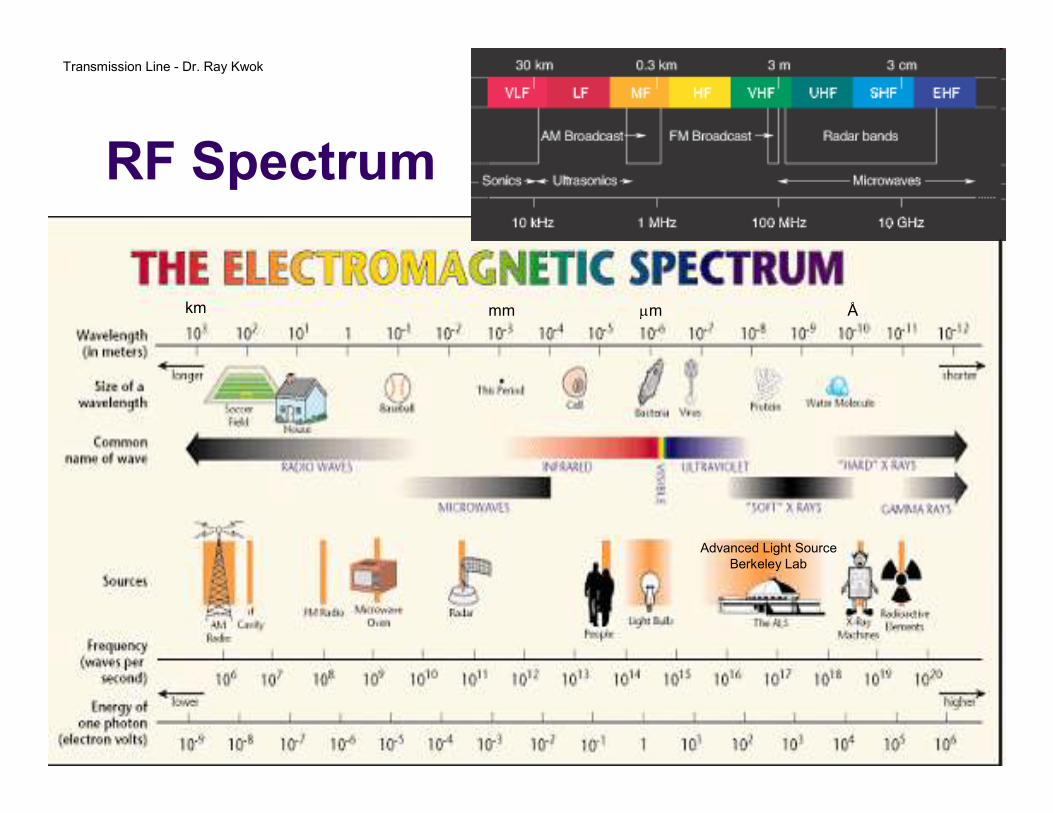
RF Spectrum
Advanced Light SourceBerkeley Lab
km mm µm Å
Transmission Line - Dr. Ray Kwok
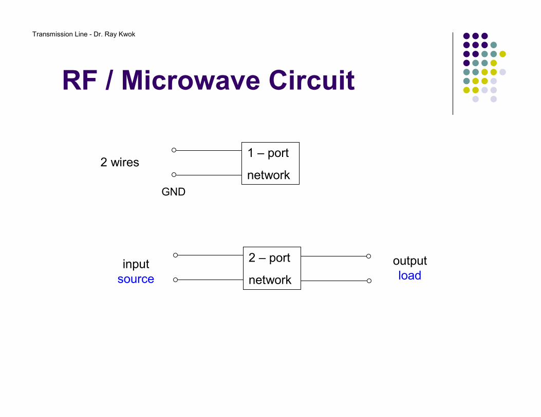
RF / Microwave Circuit
1 – port
network2 wires
GND
2 – port
networkinput
source
outputload
Transmission Line - Dr. Ray Kwok
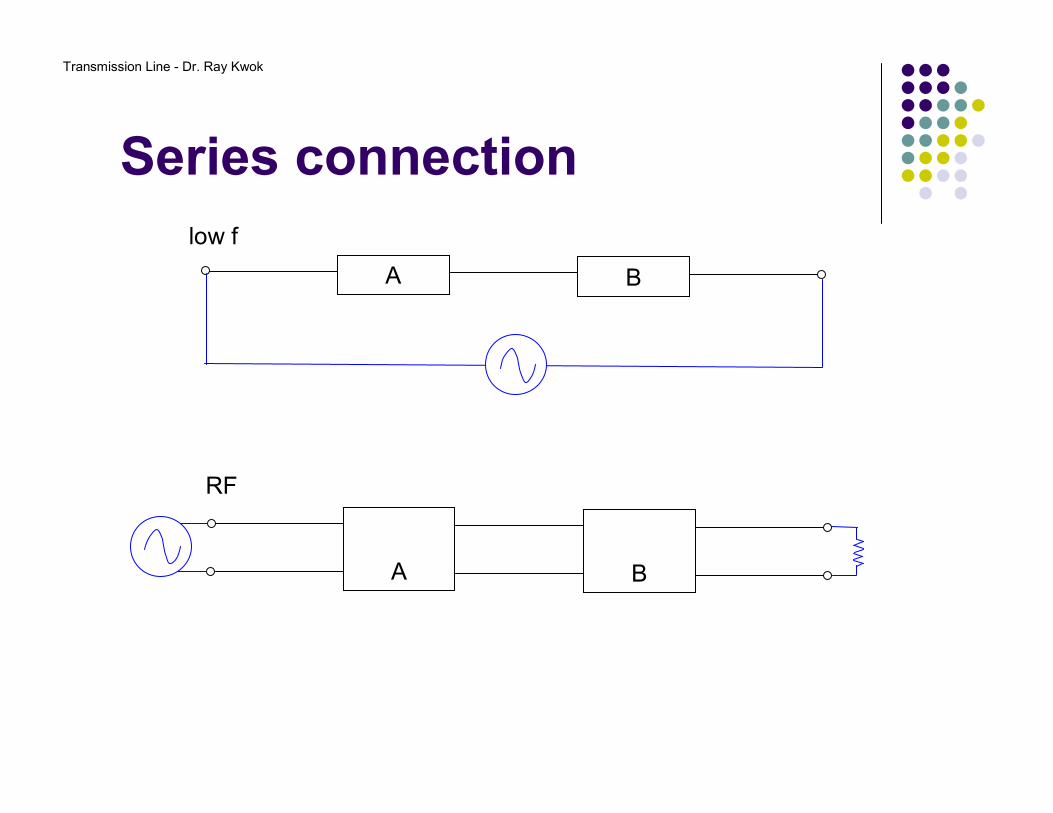
Series connection
A B
A B
RF
low f
Transmission Line - Dr. Ray Kwok
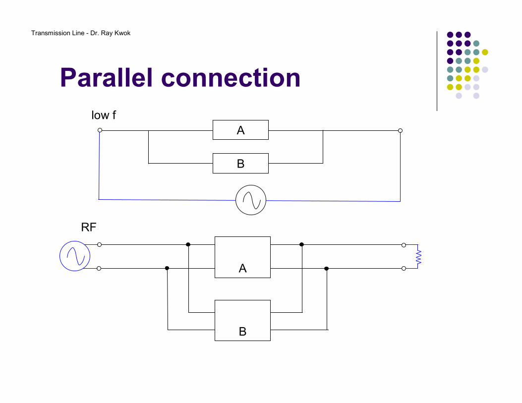
Parallel connection
Alow f
B
RF
A
B
Transmission Line - Dr. Ray Kwok
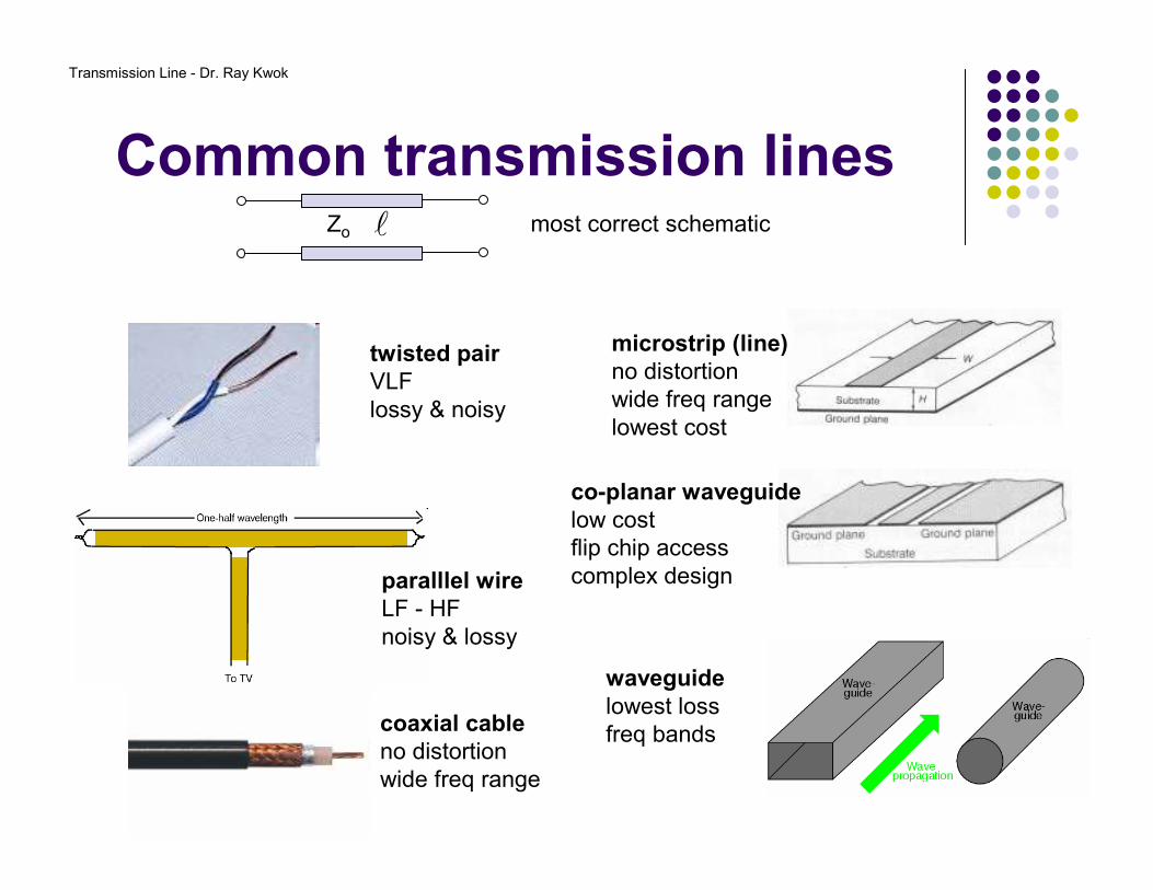
Common transmission linesmost correct schematic
twisted pair
VLFlossy & noisy
paralllel wire
LF - HFnoisy & lossy
coaxial cable
no distortionwide freq range
microstrip (line)
no distortionwide freq rangelowest cost
co-planar waveguide
low costflip chip accesscomplex design
waveguide
lowest lossfreq bands
lZo
Transmission Line - Dr. Ray Kwok
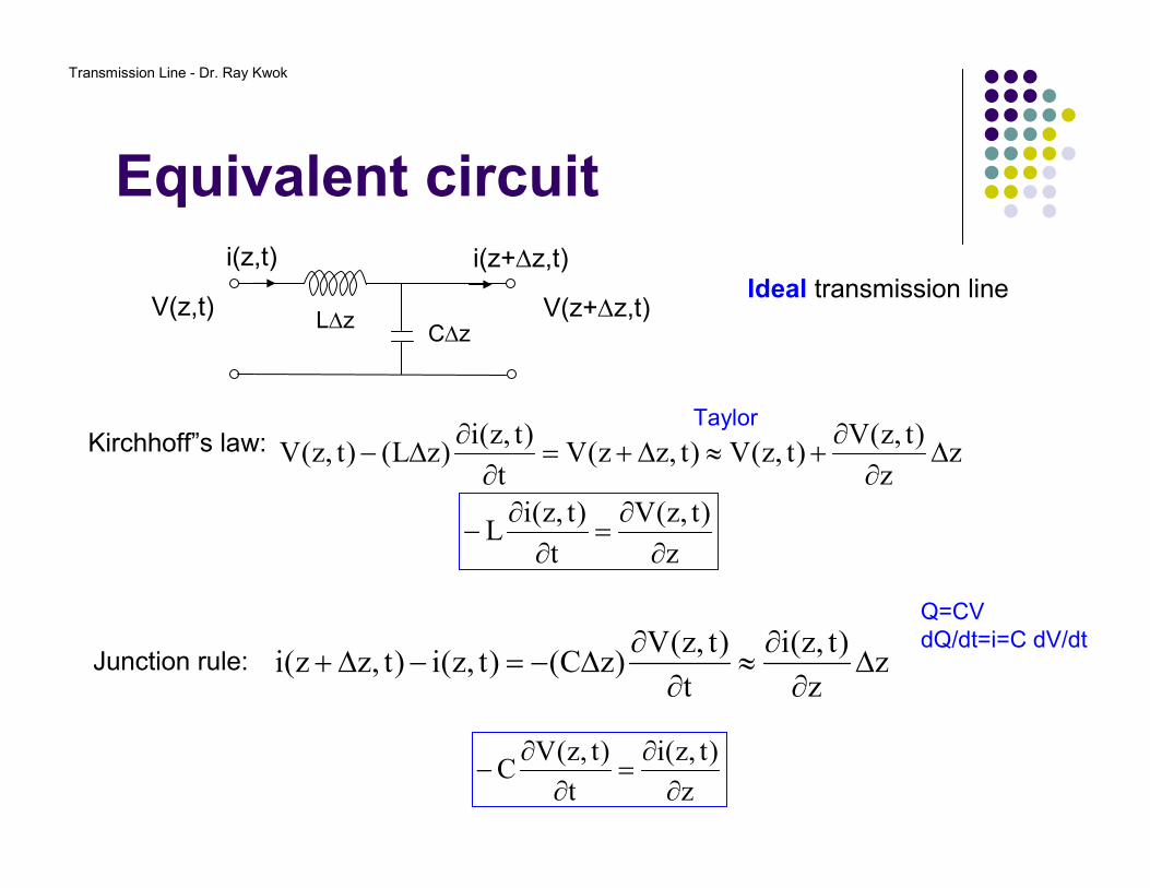
Equivalent circuit
zz
)t,z(V)t,z(V)t,zz(V
t
)t,z(i)zL()t,z(V ∆
∂∂
+≈∆+=∂
∂∆−
z
)t,z(V
t
)t,z(iL
∂∂
=∂
∂−
zz
)t,z(i
t
)t,z(V)zC()t,z(i)t,zz(i ∆
∂∂
≈∂
∂∆−=−∆+
L∆zC∆z
V(z,t) V(z+∆z,t)
i(z+∆z,t)i(z,t)
Kirchhoff”s law:Taylor
Junction rule:
z
)t,z(i
t
)t,z(VC
∂∂
=∂
∂−
Q=CVdQ/dt=i=C dV/dt
Ideal transmission line
Transmission Line - Dr. Ray Kwok
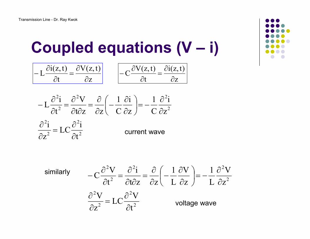
Coupled equations (V – i)
z
)t,z(V
t
)t,z(iL
∂∂
=∂
∂−
z
)t,z(i
t
)t,z(VC
∂∂
=∂
∂−
2
2
2
2
2
22
2
2
t
iLC
z
i
z
i
C
1
z
i
C
1
zzt
V
t
iL
∂∂
=∂∂
∂∂
−=
∂∂
−∂∂
=∂∂
∂=
∂∂
−
current wave
2
2
2
2
2
22
2
2
t
VLC
z
V
z
V
L
1
z
V
L
1
zzt
i
t
VC
∂∂
=∂∂
∂∂
−=
∂∂
−∂∂
=∂∂
∂=
∂∂
−similarly
voltage wave
Transmission Line - Dr. Ray Kwok
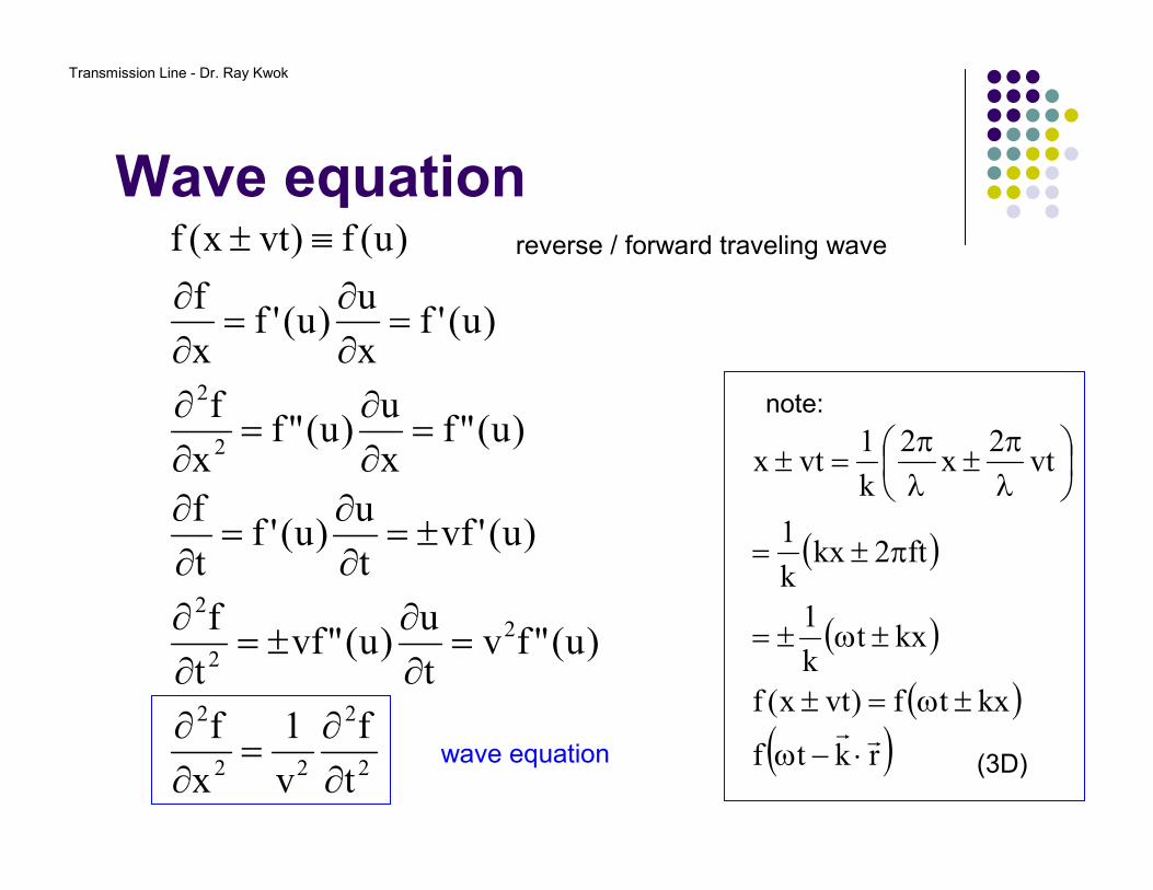
Wave equation
2
2
22
2
2
2
2
2
2
t
f
v
1
x
f
)u("fvt
u)u("vf
t
f
)u('vft
u)u('f
t
f
)u("fx
u)u("f
x
f
)u('fx
u)u('f
x
f
)u(f)vtx(f
∂∂
=∂∂
=∂∂
±=∂∂
±=∂∂
=∂∂
=∂∂
=∂∂
=∂∂
=∂∂
≡± reverse / forward traveling wave
wave equation
( )
( )
( )( )rktf
kxtf)vtx(f
kxtk
1
ft2kxk
1
vt2
x2
k
1vtx
rr⋅−ω
±ω=±
±ω±=
π±=
λπ
±λπ
=±
note:
(3D)
Transmission Line - Dr. Ray Kwok
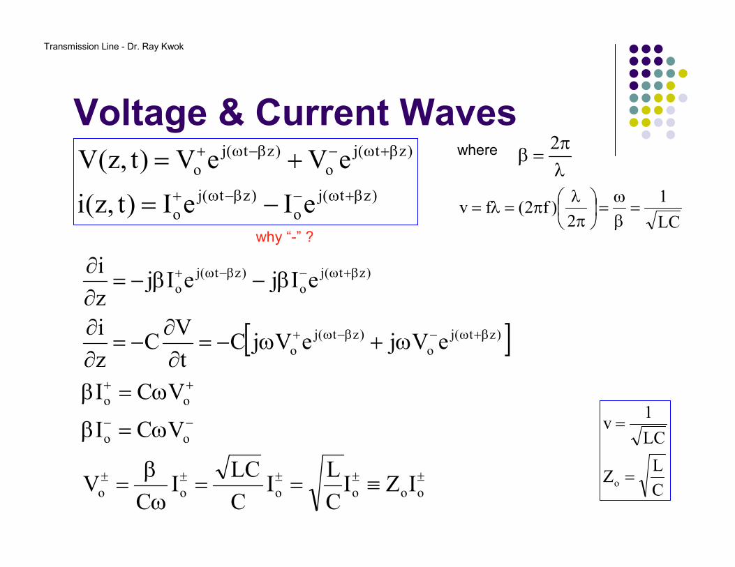
Voltage & Current Waves
)zt(j
o
)zt(j
o
)zt(j
o
)zt(j
o
eIeI)t,z(i
eVeV)t,z(V
β+ω−β−ω+
β+ω−β−ω+
−=
+= λπ
=β2
[ ]
±±±±±
−−
++
β+ω−β−ω+
β+ω−β−ω+
≡==ω
β=
ω=β
ω=β
ω+ω−=∂∂
−=∂∂
β−β−=∂∂
oooooo
oo
oo
)zt(j
o
)zt(j
o
)zt(j
o
)zt(j
o
IZIC
LI
C
LCI
CV
VCI
VCI
eVjeVjCt
VC
z
i
eIjeIjz
i
where
LC
1
2)f2(fv =
βω
=
π
λπ=λ=
C
LZ
LC
1v
o =
=
why “-” ?
Transmission Line - Dr. Ray Kwok
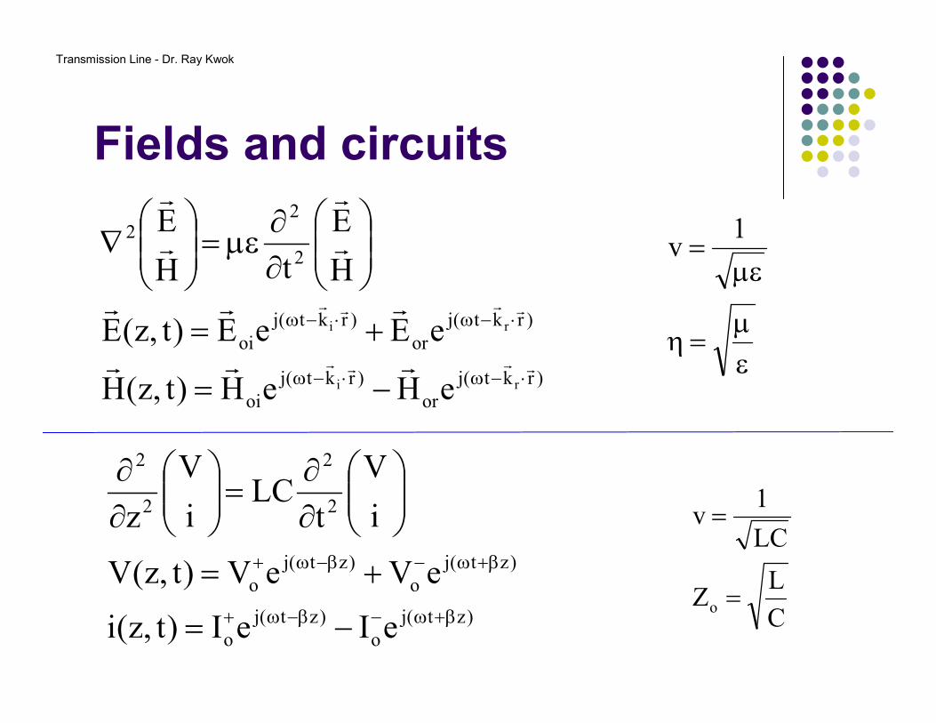
Fields and circuits
)rkt(j
or
)rkt(j
oi
)rkt(j
or
)rkt(j
oi
2
22
ri
ri
eHeH)t,z(H
eEeE)t,z(E
H
E
tH
E
rrrr
rrrr
rrr
rrr
r
r
r
r
⋅−ω⋅−ω
⋅−ω⋅−ω
−=
+=
∂∂
µε=
∇
)zt(j
o
)zt(j
o
)zt(j
o
)zt(j
o
2
2
2
2
eIeI)t,z(i
eVeV)t,z(V
i
V
tLC
i
V
z
β+ω−β−ω+
β+ω−β−ω+
−=
+=
∂∂
=
∂∂
εµ
=η
µε=
1v
C
LZ
LC
1v
o =
=
Transmission Line - Dr. Ray Kwok
What is Zo?
• Characteristic Impedance.• 50 ohms for most communications system,• 75 ohms for TV cable.• Measure 75 ohms with a ohmmeter?• Two 75Ω cables together (in series) makes a 150Ω cable?• 75 + 75 = 75 !!!!• What does Zo represent?
Transmission Line - Dr. Ray Kwok
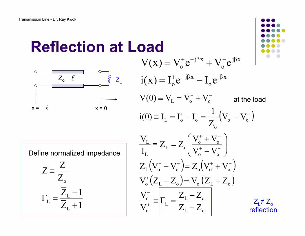
Reflection at Load
xj
o
xj
o
xj
o
xj
o
eIeI)x(i
eVeV)x(V
β−β−+
β−β−+
−=
+=
( )
( ) ( )( ) ( )
oL
oLL
o
o
oLooLo
oooooL
oo
oooL
L
L
oo
o
ooL
ooL
ZZ
ZZ
V
V
ZZVZZV
VVZVVZ
VV
VVZZ
I
V
VVZ
1III)0(i
VVV)0(V
+−
=Γ≡
+=−
+=−
−+
=≡
−=−=≡
+=≡
+
−
−+
−+−+
−+
−+
−+−+
−+
lZo
l−
ZL
x = 0x =
at the load
Define normalized impedance
1Z
1Z
Z
ZZ
L
LL
o
+−
=Γ
≡
ZL≠ Zo
reflection
Transmission Line - Dr. Ray Kwok
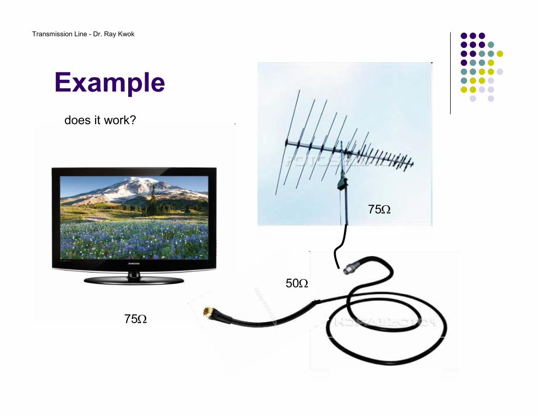
Example
75Ω
75Ω
50Ω
does it work?
Transmission Line - Dr. Ray Kwok
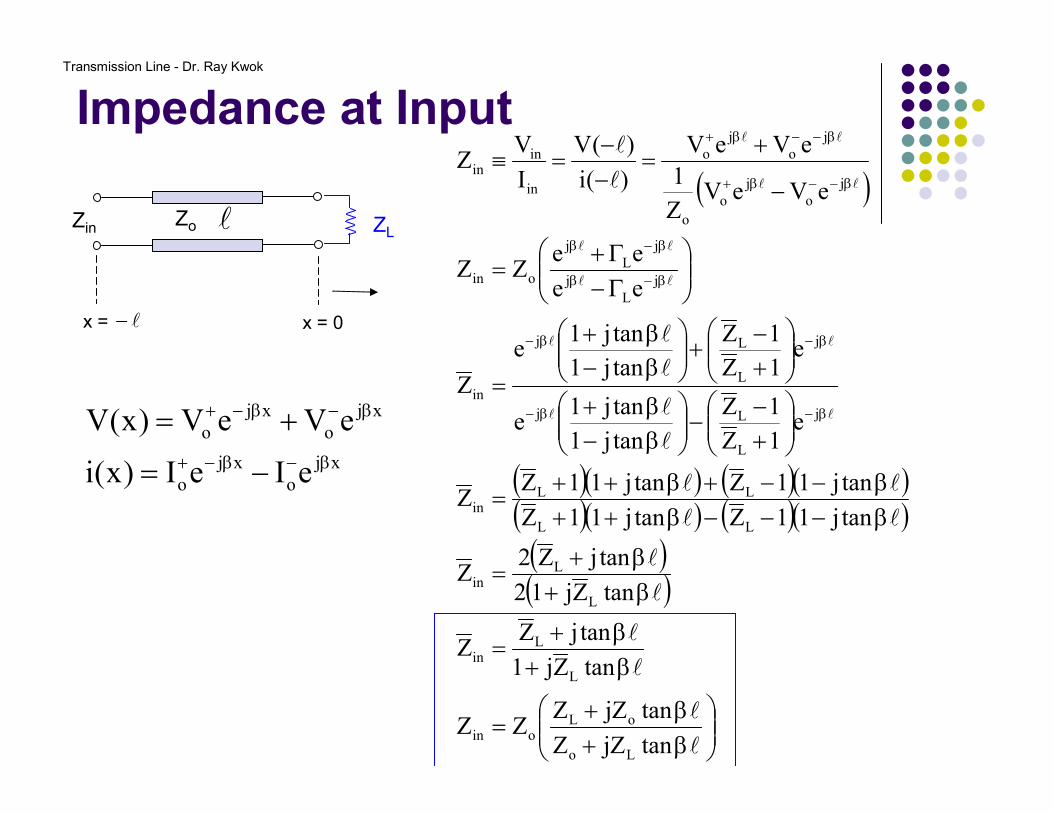
Impedance at Input
xj
o
xj
o
xj
o
xj
o
eIeI)x(i
eVeV)x(V
β−β−+
β−β−+
−=
+=
lZo
l−
ZL
x = 0x =
( )
( )( ) ( )( )( )( ) ( )( )
( )( )
β+β+
=
β+β+
=
β+β+
=
β−−−β++β−−+β++
=
+−
−
β−β+
+−
+
β−β+
=
Γ−Γ+
=
−
+=
−−
=≡
β−β−
β−β−
β−β
β−β
β−−β+
β−−β+
l
l
l
l
l
l
ll
ll
l
l
l
l
l
l
ll
ll
ll
ll
ll
ll
tanjZZ
tanjZZZZ
tanZj1
tanjZZ
tanZj12
tanjZ2Z
tanj11Ztanj11Z
tanj11Ztanj11ZZ
e1Z
1Z
tanj1
tanj1e
e1Z
1Z
tanj1
tanj1e
Z
ee
eeZZ
eVeVZ
1
eVeV
)(i
)(V
I
VZ
Lo
oLoin
L
Lin
L
Lin
LL
LLin
j
L
Lj
j
L
Lj
in
j
L
j
j
L
j
oin
j
o
j
o
o
j
o
j
o
in
inin
Zin

Transmission Line - Dr. Ray Kwok
Exercise
lZo
l−
ZL
x = 0x =
Zin
Zo = 50 ΩZL = 100ΩZin = ?
For length = λ/8? λ/4? λ/2?
What if Zo = ZL = 50Ω? Would the length make any difference?
β+β+
=
β+β+
=
l
l
l
l
tanjZZ
tanjZZZZ
tanZj1
tanjZZ
Lo
oLoin
L
Lin
50Ω (-37o)
25Ω
100Ω
Zin=Zo=ZL
Transmission Line - Dr. Ray Kwok
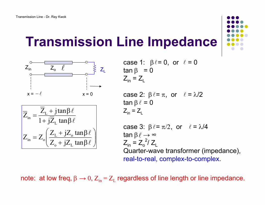
Transmission Line Impedance
β+β+
=
β+β+
=
l
l
l
l
tanjZZ
tanjZZZZ
tanZj1
tanjZZ
Lo
oLoin
L
Lin
case 1: β = 0, or = 0tan β = 0Zin = ZL
case 2: β = π, or = λ/2tan β = 0 Zin = ZL
case 3: β = π/2, or = λ/4tan β → ∞Zin = Zo
2/ ZL
Quarter-wave transformer (impedance),real-to-real, complex-to-complex.
l l
l l
l
l l
l
lZo
l−
ZL
x = 0x =
Zin
note: at low freq, β → 0, Zin = ZL regardless of line length or line impedance.
Transmission Line - Dr. Ray Kwok
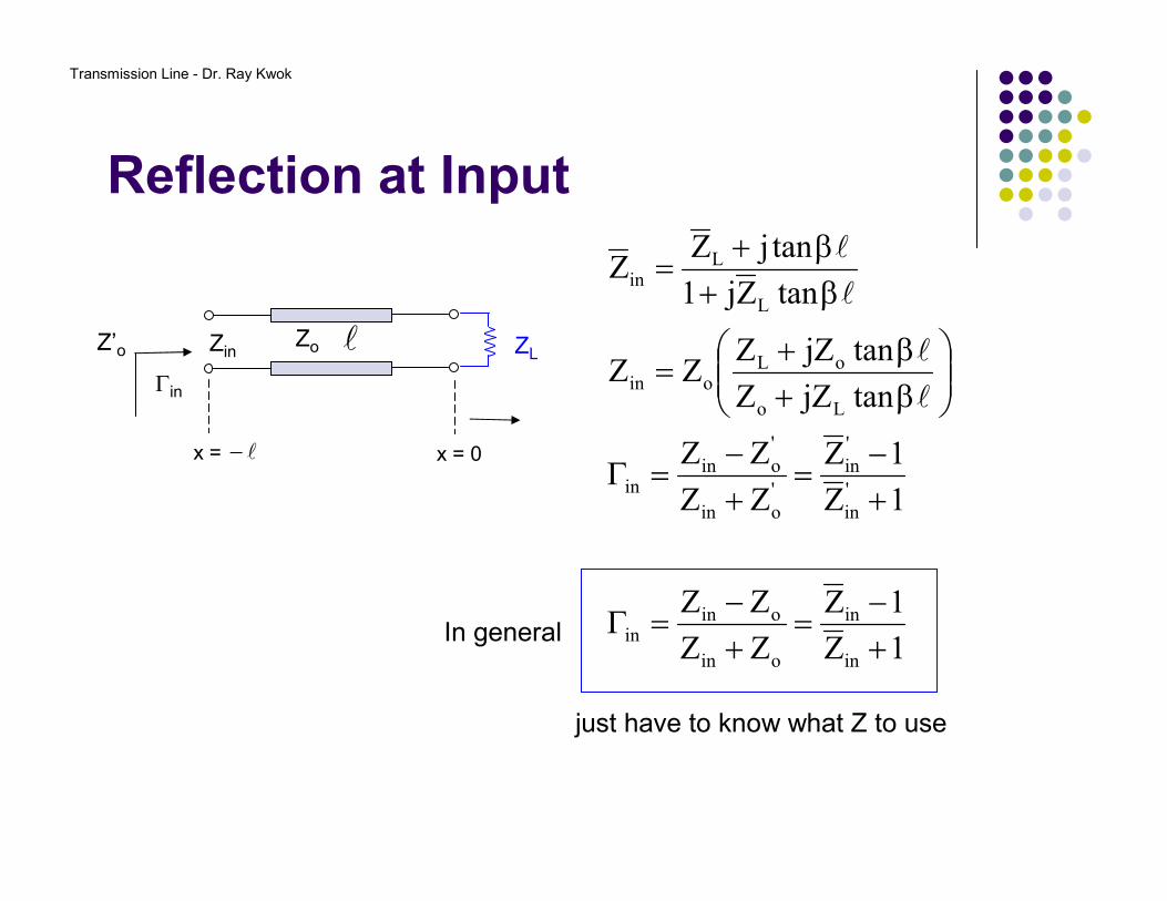
Reflection at Input
lZo
l−
ZL
x = 0x =
Zin
Γin
Z’o
1Z
1Z
ZZ
ZZ
1Z
1Z
ZZ
ZZ
tanjZZ
tanjZZZZ
tanZj1
tanjZZ
in
in
oin
oinin
'
in
'
in
'
oin
'
oinin
Lo
oLoin
L
Lin
+−
=+−
=Γ
+−
=+−
=Γ
β+β+
=
β+β+
=
l
l
l
l
In general
just have to know what Z to use
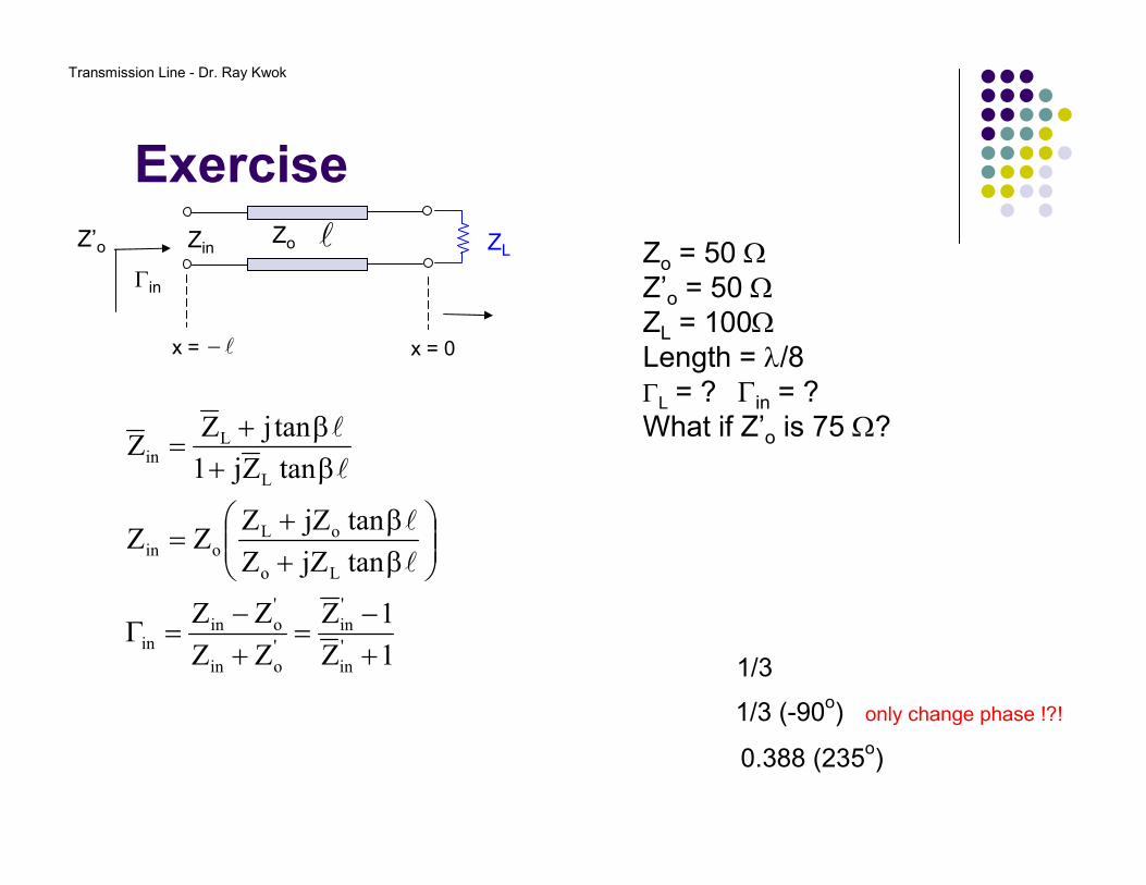
Transmission Line - Dr. Ray Kwok
Exercise
1Z
1Z
ZZ
ZZ
tanjZZ
tanjZZZZ
tanZj1
tanjZZ
'
in
'
in
'
oin
'
oinin
Lo
oLoin
L
Lin
+−
=+−
=Γ
β+β+
=
β+β+
=
l
l
l
l
lZo
l−
ZL
x = 0x =
Zin
Γin
Z’o Zo = 50 ΩZ’o = 50 ΩZL = 100ΩLength = λ/8ΓL = ? Γin = ?What if Z’o is 75 Ω?
1/3
1/3 (-90o) only change phase !?!
0.388 (235o)
Transmission Line - Dr. Ray Kwok
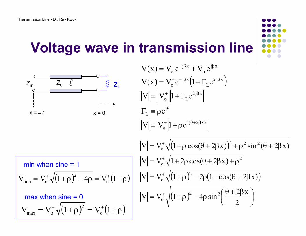
Voltage wave in transmission line
( )
)x2(j
o
j
L
xj2
Lo
xj2
L
xj
o
xj
o
xj
o
e1VV
e
e1VV
e1eV)x(V
eVeV)x(V
β+θ+
θ
β+
ββ−+
β−β−+
ρ+=
ρ≡Γ
Γ+=
Γ+=
+=
l−
lZo ZL
x = 0x =
Zin
( )
( ) ( )
( )
β+θρ−ρ+=
β+θ−ρ−ρ+=
ρ+β+θρ+=
β+θρ+β+θρ+=
+
+
+
+
2
x2sin41VV
)x2cos(121VV
)x2cos(21VV
)x2(sin)x2cos(1VV
22
o
2
o
2
o
222
o
max when sine = 0
( ) ( )ρ+=ρ+= ++ 1V1VV o
2
omax
( ) ( )ρ−=ρ−ρ+= ++ 1V41VV o
2
omin
min when sine = 1
Transmission Line - Dr. Ray Kwok
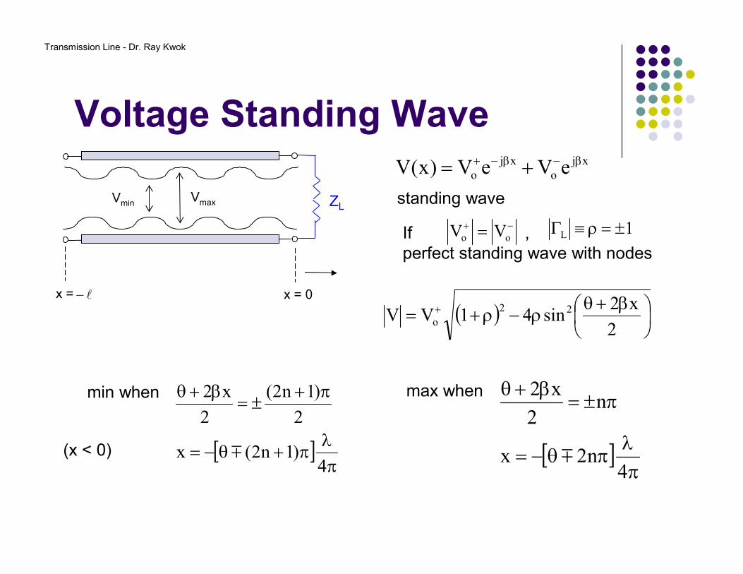
Voltage Standing Wave
( )
β+θρ−ρ+= +
2
x2sin41VV 22
o
l−
ZL
x = 0x =
Vmin Vmax
max when
[ ]π
λπθ−=
π±=β+θ
4n2x
n2
x2
m
min when
[ ]π
λπ+θ−=
π+±=
β+θ
4)1n2(x
2
)1n2(
2
x2
m(x < 0)
xj
o
xj
o eVeV)x(V β−β−+ +=
standing wave
−+ = oo VVIf ,perfect standing wave with nodes
1L ±=ρ≡Γ
Transmission Line - Dr. Ray Kwok
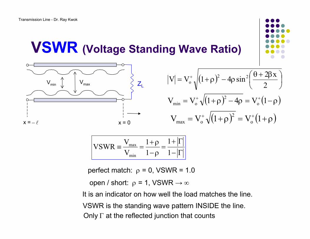
VSWR (Voltage Standing Wave Ratio)
l−
ZL
x = 0x =
( ) ( )ρ−=ρ−ρ+= ++ 1V41VV o
2
omin
( )
β+θρ−ρ+= +
2
x2sin41VV 22
o
( ) ( )ρ+=ρ+= ++ 1V1VV o
2
omax
Vmin Vmax
Γ−
Γ+=
ρ−ρ+
=≡1
1
1
1
V
VVSWR
min
max
perfect match: ρ = 0, VSWR = 1.0
open / short: ρ = 1, VSWR → ∞
It is an indicator on how well the load matches the line.
VSWR is the standing wave pattern INSIDE the line.
Only Γ at the reflected junction that counts
Transmission Line - Dr. Ray Kwok
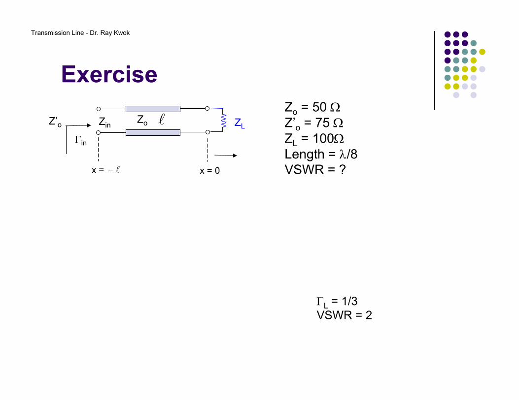
Exercise
lZo
l−
ZL
x = 0x =
Zin
Γin
Z’o
Zo = 50 ΩZ’o = 75 ΩZL = 100ΩLength = λ/8VSWR = ?
ΓL = 1/3VSWR = 2
Transmission Line - Dr. Ray Kwok
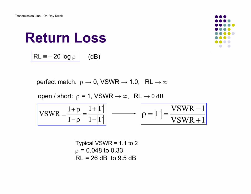
Return Loss
Γ−
Γ+=
ρ−ρ+
≡1
1
1
1VSWR
perfect match: ρ → 0, VSWR → 1.0, RL → ∞
open / short: ρ = 1, VSWR → ∞, RL → 0 dB
RL ≡ − 20 log ρ (dB)
Typical VSWR = 1.1 to 2ρ = 0.048 to 0.33RL = 26 dB to 9.5 dB
1VSWR
1VSWR
+−
=Γ=ρ
Transmission Line - Dr. Ray Kwok
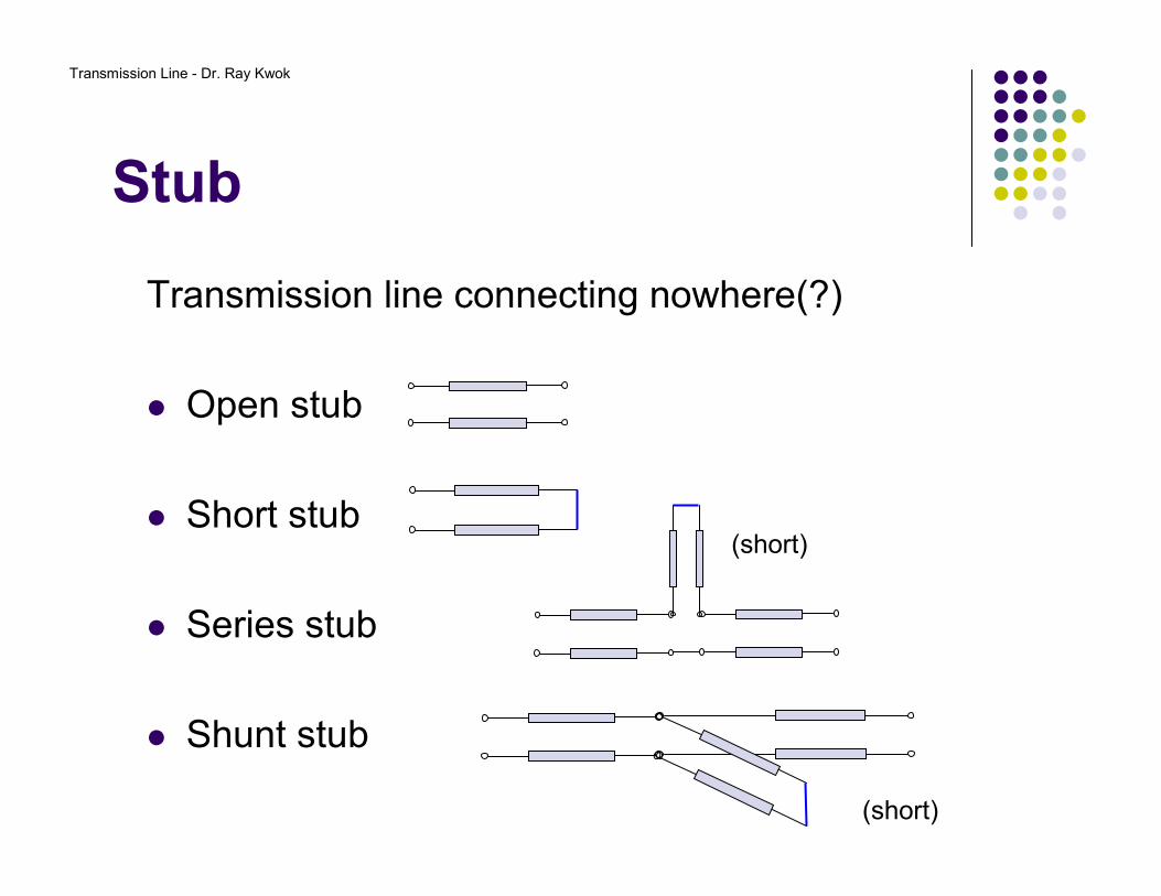
Transmission line connecting nowhere(?)
Open stub
Short stub
Series stub
Shunt stub
Stub
(short)
(short)
Transmission Line - Dr. Ray Kwok
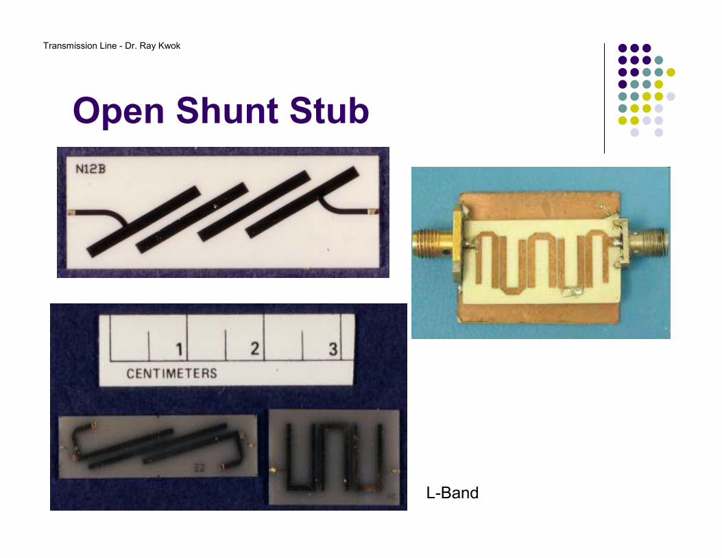
Open Shunt Stub
L-Band
Transmission Line - Dr. Ray Kwok
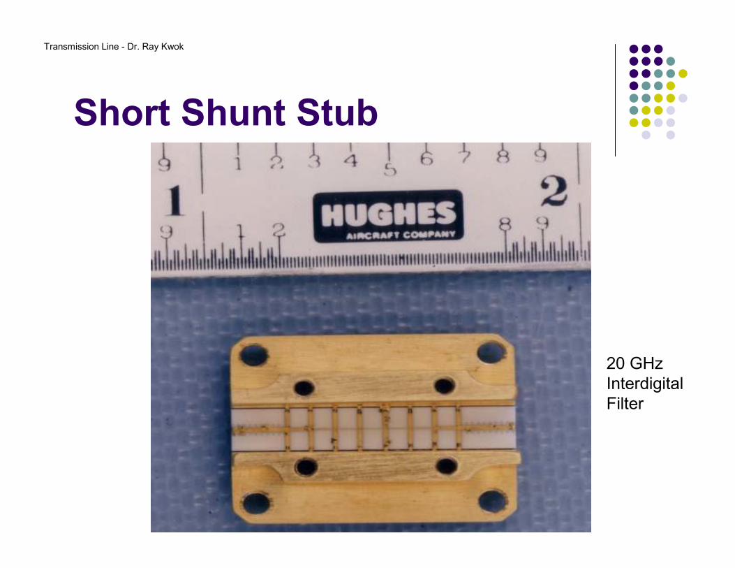
Short Shunt Stub
20 GHzInterdigitalFilter
Transmission Line - Dr. Ray Kwok
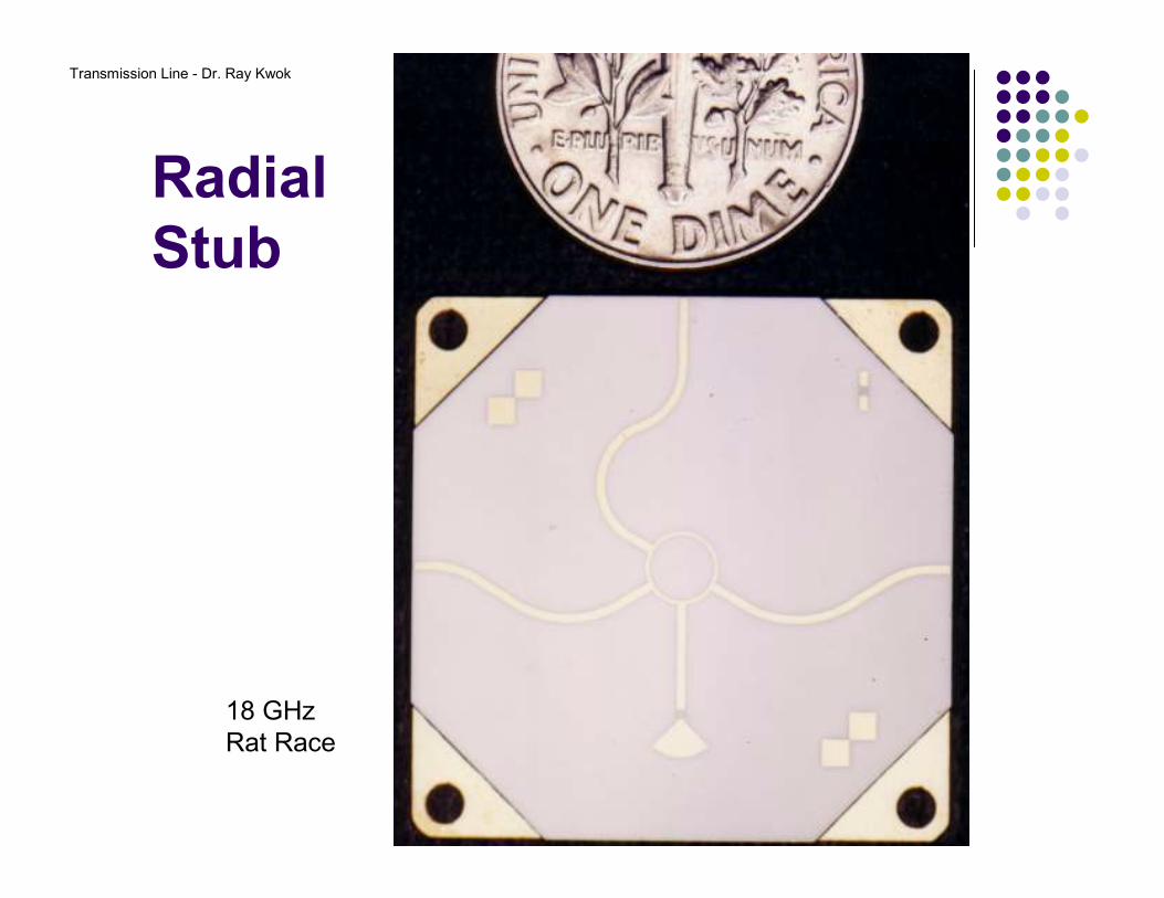
Radial
Stub
18 GHzRat Race
Transmission Line - Dr. Ray Kwok
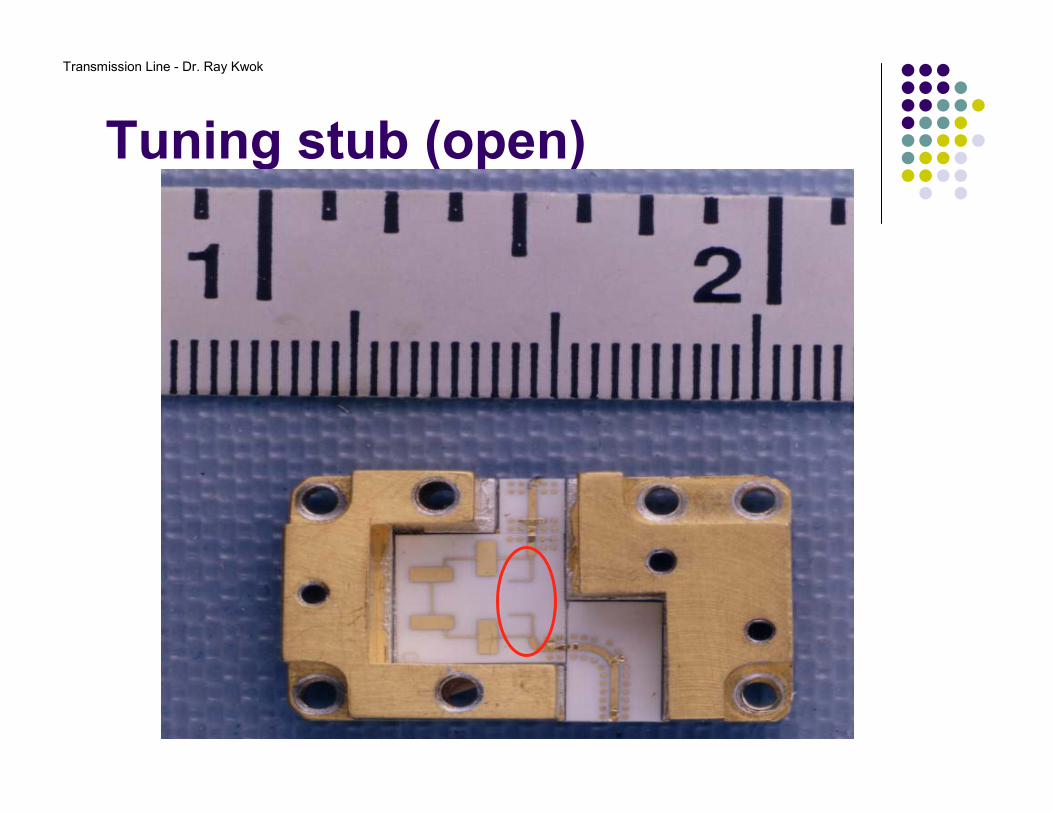
Tuning stub (open)
Transmission Line - Dr. Ray Kwok
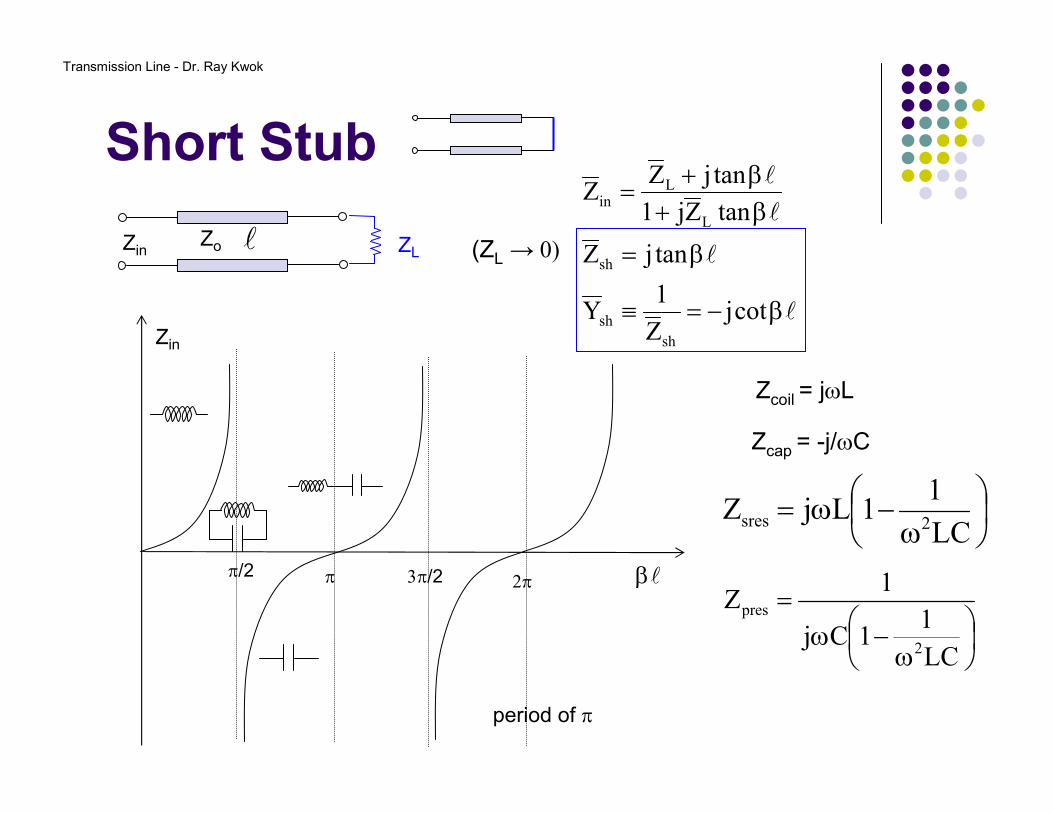
Short Stub
l
l
l
l
β−=≡
β=
β+β+
=
cotjZ
1Y
tanjZ
tanZj1
tanjZZ
sh
sh
sh
L
Lin
lZo ZLZin (ZL → 0)
Zin
lβπ/2 π 3π/2 2π
Zcoil = jωL
Zcap = -j/ωC
ω
−ω=LC
11LjZ
2sres
ω
−ω=
LC
11Cj
1Z
2
pres
period of π

Transmission Line - Dr. Ray Kwok
Open Stub
l
l
l
l
β=
β−=
β+β+
=
tanjY
cotjZ
tanZj1
tanjZZ
op
op
L
Lin
lZo ZLZin
(ZL → ∞)
Zin
lβπ/2 π 3π/2 2π
Zcoil = jωL
Zcap = -j/ωC
ω
−ω=LC
11LjZ
2sres
ω
−ω=
LC
11Cj
1Z
2
pres
period of π
Transmission Line - Dr. Ray Kwok
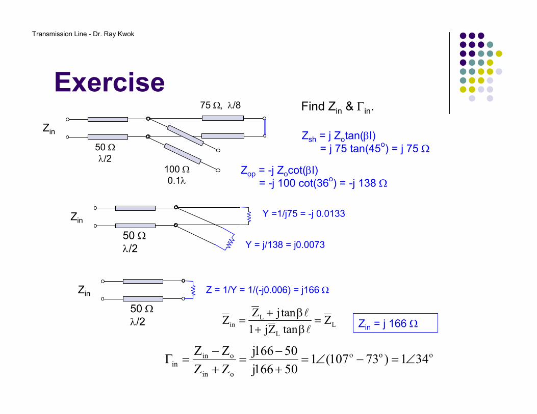
Exercise
L
L
Lin Z
tanZj1
tanjZZ =
β+β+
=l
l
50 Ωλ/2
75 Ω, λ/8
100 Ω0.1λ
Zin
50 Ωλ/2
Zin
Zsh = j Zotan(βl)= j 75 tan(45o) = j 75 Ω
Zop = -j Zocot(βl)= -j 100 cot(36o) = -j 138 Ω
Y =1/j75 = -j 0.0133
Y = j/138 = j0.0073
50 Ωλ/2
Zin Z = 1/Y = 1/(-j0.006) = j166 Ω
Zin = j 166 Ω
Find Zin & Γin.
ooo
oin
oinin 341)73107(1
50166j
50166j
ZZ
ZZ∠=−∠=
+−
=+−
=Γ
Transmission Line - Dr. Ray Kwok
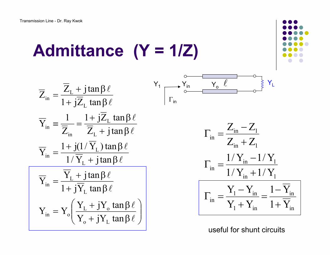
β+β+
=
β+β+
=
β+β+
=
β+β+
=≡
β+β+
=
l
l
l
l
l
l
l
l
l
l
tanjYY
tanjYYYY
tanYj1
tanjYY
tanjY/1
tan)Y/1(j1Y
tanjZ
tanZj1
Z
1Y
tanZj1
tanjZZ
Lo
oLoin
L
Lin
L
Lin
L
L
in
in
L
Lin
in
in
in1
in1in
1in
1inin
1in
1inin
Y1
Y1
YY
YY
Y/1Y/1
Y/1Y/1
ZZ
ZZ
+−
=+−
=Γ
+−
=Γ
+−
=Γ
l YLY1 Yo
Γin
Yin
useful for shunt circuits
Admittance (Y = 1/Z)
Transmission Line - Dr. Ray Kwok
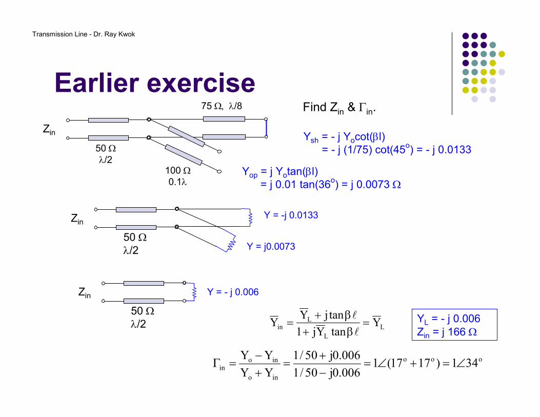
Earlier exercise
L
L
Lin Y
tanYj1
tanjYY =
β+β+
=l
l
50 Ωλ/2
75 Ω, λ/8
100 Ω0.1λ
Zin
50 Ωλ/2
Zin
Ysh = - j Yocot(βl)= - j (1/75) cot(45o) = - j 0.0133
Yop = j Yotan(βl)= j 0.01 tan(36o) = j 0.0073 Ω
Y = -j 0.0133
Y = j0.0073
50 Ωλ/2
Zin Y = - j 0.006
YL = - j 0.006Zin = j 166 Ω
Find Zin & Γin.
ooo
ino
inoin 341)1717(1
006.0j50/1
006.0j50/1
YY
YY∠=+∠=
−+
=+−
=Γ
Transmission Line - Dr. Ray Kwok
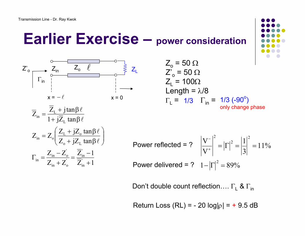
Earlier Exercise – power consideration
1Z
1Z
ZZ
ZZ
tanjZZ
tanjZZZZ
tanZj1
tanjZZ
'
in
'
in
'
oin
'
oinin
Lo
oLoin
L
Lin
+−
=+−
=Γ
β+β+
=
β+β+
=
l
l
l
l
Zo = 50 ΩZ’o = 50 ΩZL = 100ΩLength = λ/8ΓL = ? Γin = ? 1/3 1/3 (-90o)
only change phase
Power reflected = ?
%891
%113
1
V
V
2
22
2
=Γ−
==Γ=+
−
Power delivered = ?
Don’t double count reflection…. ΓL & Γin
Return Loss (RL) = - 20 log|ρ| = + 9.5 dB
lZo
l−
ZL
x = 0x =
Zin
Γin
Z’o
Transmission Line - Dr. Ray Kwok
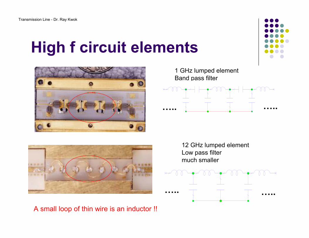
High f circuit elements
1 GHz lumped elementBand pass filter
CAP
C=ID=
1 pFC1
CAP
C=ID=
1 pFC3 IND
L=ID=
1 nHL3 IND
L=ID=
1 nHL4
CAP
C=ID=
1 pFC4
CAP
C=ID=
1 pFC5
CAP
C=ID=
1 pFC6 IND
L=ID=
1 nHL7
CAP
C=ID=
1 pFC2
….. …..
CAP
C=ID=
1 pFC1
IND
L=ID=
1 nHL3
IND
L=ID=
1 nHL4
CAP
C=ID=
1 pFC6
IND
L=ID=
1 nHL7
CAP
C=ID=
1 pFC4
IND
L=ID=
1 nHL1 ….. …..
12 GHz lumped elementLow pass filtermuch smaller
A small loop of thin wire is an inductor !!
Transmission Line - Dr. Ray Kwok
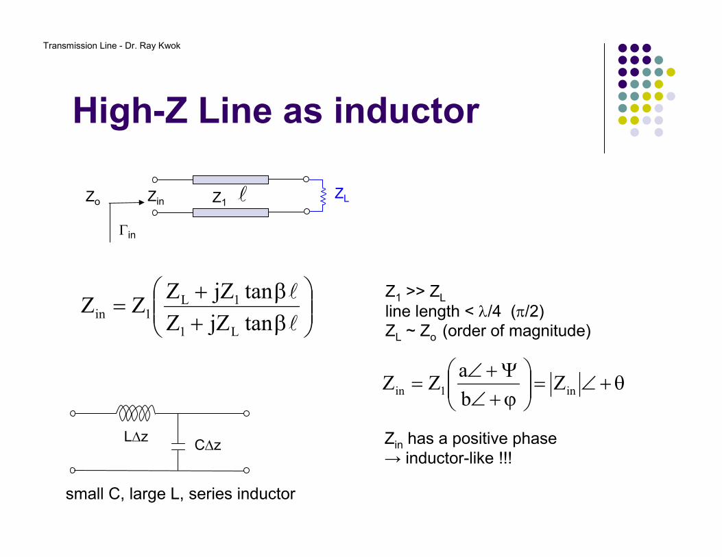
High-Z Line as inductor
β+β+
=l
l
tanjZZ
tanjZZZZ
L1
1L1in
l ZLZo Z1
Γin
Zin
Z1 >> ZL
line length < λ/4 (π/2)ZL ~ Zo (order of magnitude)
θ+∠=
ϕ+∠Ψ+∠
= in1in Zb
aZZ
Zin has a positive phase → inductor-like !!!
L∆zC∆z
small C, large L, series inductor
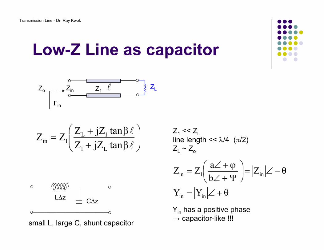
Transmission Line - Dr. Ray Kwok
Low-Z Line as capacitor
β+β+
=l
l
tanjZZ
tanjZZZZ
L1
1L1in
l ZLZo Z1
Γin
Zin
Z1 << ZL
line length << λ/4 (π/2)ZL ~ Zo
θ+∠=
θ−∠=
Ψ+∠ϕ+∠
=
inin
in1in
YY
Zb
aZZ
Yin has a positive phase → capacitor-like !!!
L∆zC∆z
small L, large C, shunt capacitor
Transmission Line - Dr. Ray Kwok
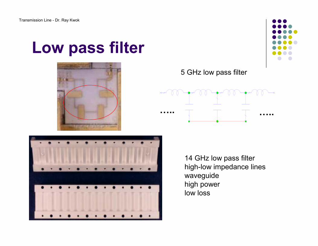
Low pass filter
5 GHz low pass filter
CAP
C=ID=
1 pFC1
IND
L=ID=
1 nHL3
IND
L=ID=
1 nHL4
CAP
C=ID=
1 pFC6
IND
L=ID=
1 nHL7
CAP
C=ID=
1 pFC4
IND
L=ID=
1 nHL1 ….. …..
14 GHz low pass filterhigh-low impedance lineswaveguidehigh powerlow loss
Transmission Line - Dr. Ray Kwok
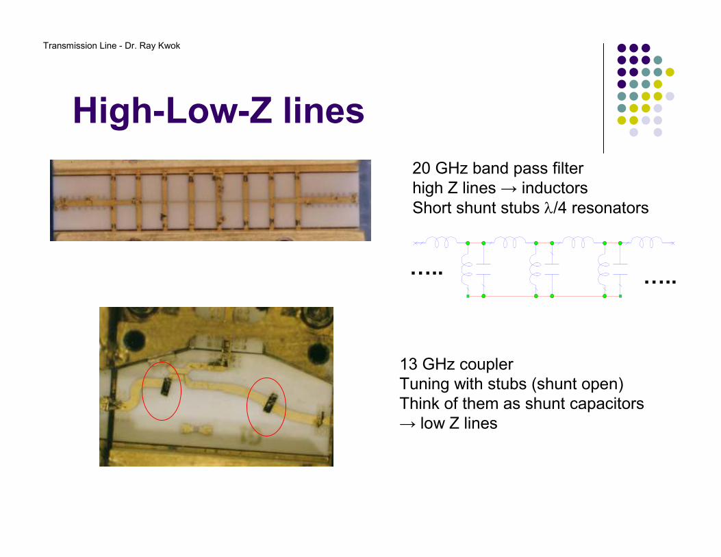
High-Low-Z lines
CAP
C=ID=
1 pFC1
IND
L=ID=
1 nHL3
IND
L=ID=
1 nHL4
CAP
C=ID=
1 pFC6 IND
L=ID=
1 nHL7
CAP
C=ID=
1 pFC4 IND
L=ID=
1 nHL1
IND
L=ID=
1 nHL2 IND
L=ID=
1 nHL5
IND
L=ID=
1 nHL6
20 GHz band pass filterhigh Z lines → inductorsShort shunt stubs λ/4 resonators
….. …..
13 GHz couplerTuning with stubs (shunt open)Think of them as shunt capacitors→ low Z lines
Transmission Line - Dr. Ray Kwok
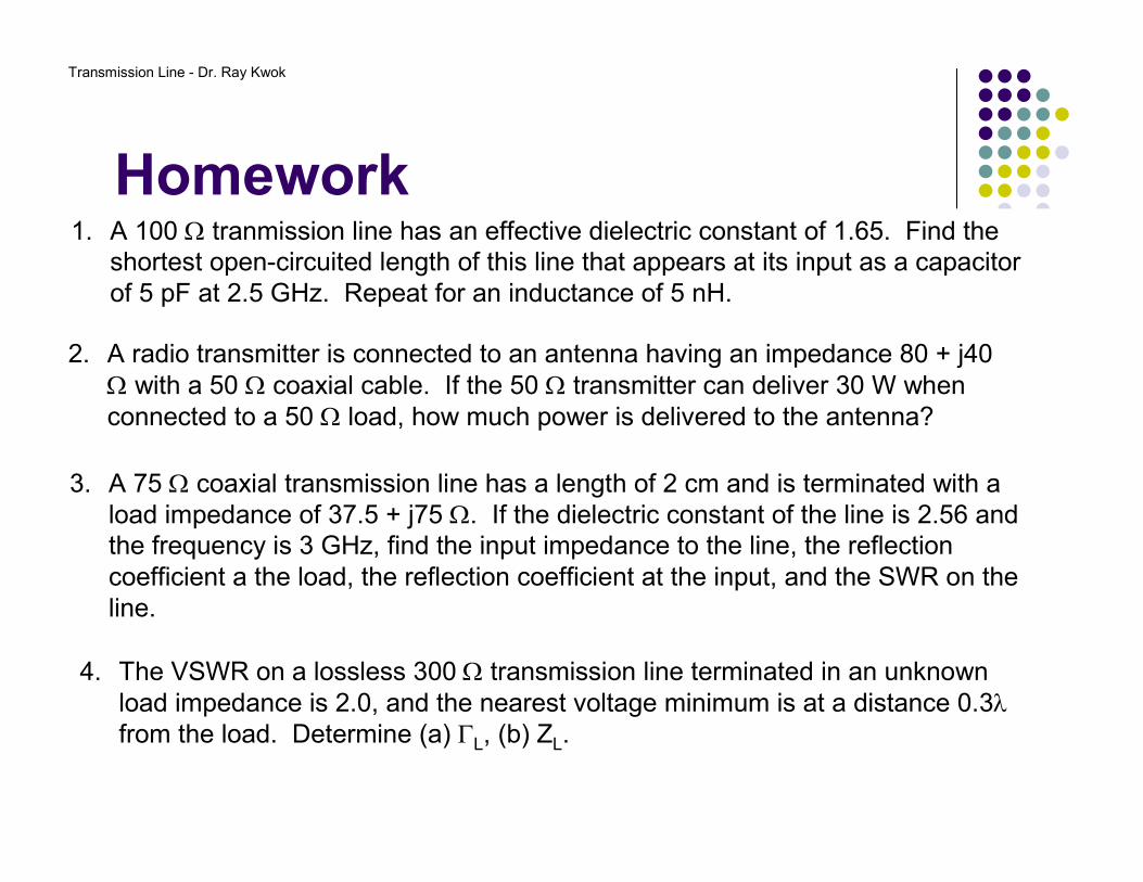
Homework1. A 100 Ω tranmission line has an effective dielectric constant of 1.65. Find the
shortest open-circuited length of this line that appears at its input as a capacitor of 5 pF at 2.5 GHz. Repeat for an inductance of 5 nH.
2. A radio transmitter is connected to an antenna having an impedance 80 + j40 Ω with a 50 Ω coaxial cable. If the 50 Ω transmitter can deliver 30 W when connected to a 50 Ω load, how much power is delivered to the antenna?
3. A 75 Ω coaxial transmission line has a length of 2 cm and is terminated with a load impedance of 37.5 + j75 Ω. If the dielectric constant of the line is 2.56 and the frequency is 3 GHz, find the input impedance to the line, the reflection coefficient a the load, the reflection coefficient at the input, and the SWR on the line.
4. The VSWR on a lossless 300 Ω transmission line terminated in an unknown load impedance is 2.0, and the nearest voltage minimum is at a distance 0.3λfrom the load. Determine (a) ΓL, (b) ZL.
Transmission Line - Dr. Ray Kwok
2.50
2.00
10
1.50
0.10
1.20
1.10
30
321.05
0.01
1.01
∞0.001.00
RL (dB)ρρρρVSWR
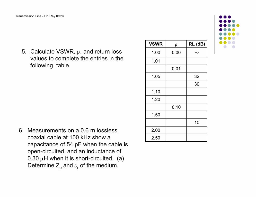
5. Calculate VSWR, ρ, and return loss values to complete the entries in the following table.
6. Measurements on a 0.6 m losslesscoaxial cable at 100 kHz show a capacitance of 54 pF when the cable is open-circuited, and an inductance of 0.30 µH when it is short-circuited. (a) Determine Zo and εr of the medium.