Lecture VI Antennas & Propagation -1- Antennas & Propagation Mischa Dohler King’s College London...
43
Lecture VI Antennas & Propagation -1- Antennas & Propagation Mischa Dohler Mischa Dohler King’s College London King’s College London Centre for Telecommunications Centre for Telecommunications Research Research
-
Upload
opal-leonard -
Category
Documents
-
view
240 -
download
0
Transcript of Lecture VI Antennas & Propagation -1- Antennas & Propagation Mischa Dohler King’s College London...
Lect
ure
VI
Ant
enna
s &
P
ropa
gatio
nA
nten
nas
&
Pro
paga
tion
-1-
Antennas
&
Propagation
Mischa DohlerMischa Dohler
King’s College LondonKing’s College London
Centre for Telecommunications ResearchCentre for Telecommunications Research
Lect
ure
VI
Ant
enna
s &
P
ropa
gatio
nA
nten
nas
&
Pro
paga
tion
-2-
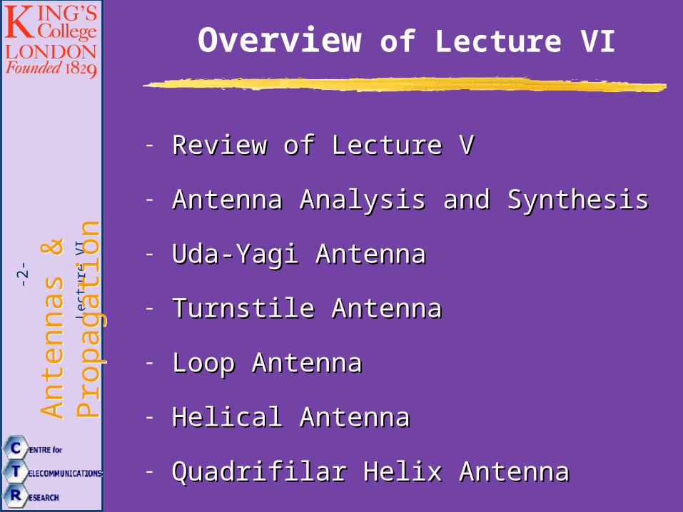
Overview of Lecture VI
- Review of Lecture VReview of Lecture V
- Antenna Analysis and SynthesisAntenna Analysis and Synthesis
- Uda-Yagi AntennaUda-Yagi Antenna
- Turnstile AntennaTurnstile Antenna
- Loop AntennaLoop Antenna
- Helical AntennaHelical Antenna
- Quadrifilar Helix AntennaQuadrifilar Helix Antenna

Lect
ure
VI
Ant
enna
s &
P
ropa
gatio
nA
nten
nas
&
Pro
paga
tion
-3- Review
Lect
ure
VI
Ant
enna
s &
P
ropa
gatio
nA
nten
nas
&
Pro
paga
tion
-4-
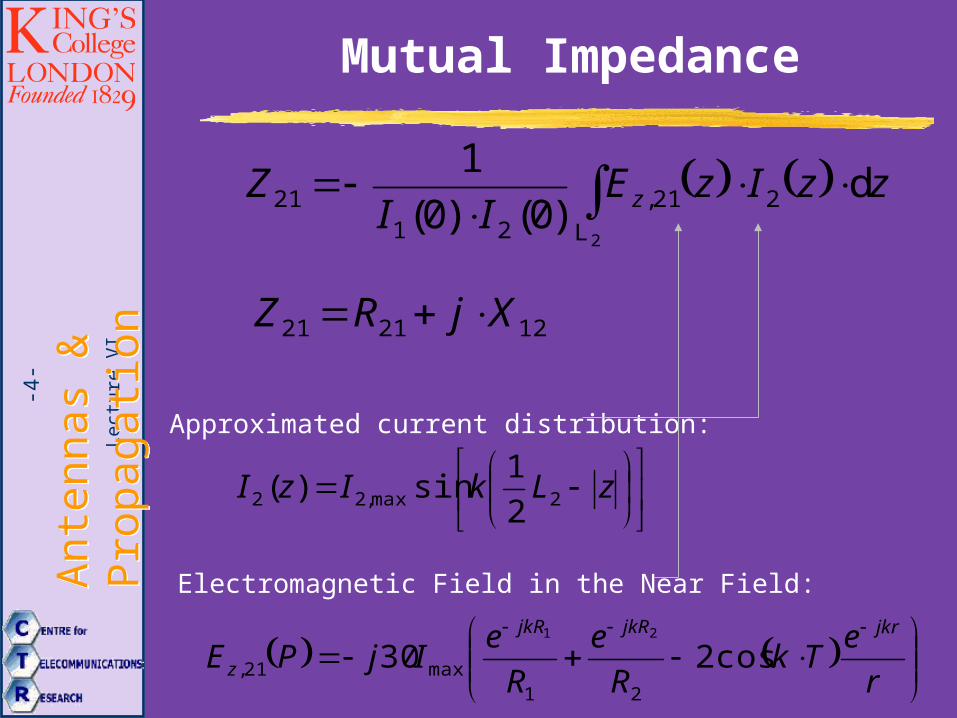
Mutual Impedance
2L
221,21
21 d)0()0(
1zzIzE
IIZ z
Approximated current distribution:
zLkIzI 2max,22 2
1sin)(
Electromagnetic Field in the Near Field:
r
eTk
R
e
R
eIjPE
jkrjkRjkR
z cos23021
max21,
21
122121 XjRZ
Lect
ure
VI
Ant
enna
s &
P
ropa
gatio
nA
nten
nas
&
Pro
paga
tion
-5-
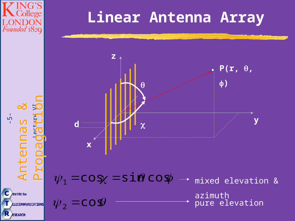
Linear Antenna Array
x
y
z
P(r, , )
cossincos1
cos2
mixed elevation & azimuth
pure elevation
d
Lect
ure
VI
Ant
enna
s &
P
ropa
gatio
nA
nten
nas
&
Pro
paga
tion
-6-
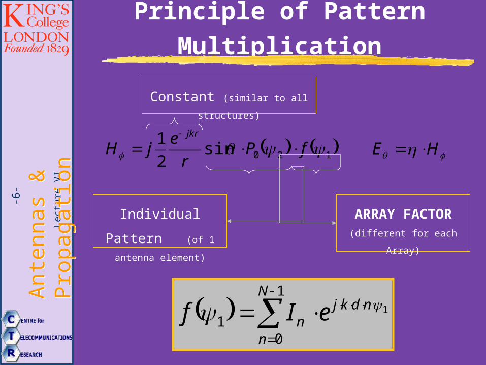
Principle of Pattern Multiplication
Individual Pattern (of 1 antenna element)
120sin2
1 fPr
ejH
jkr
HE
ARRAY FACTOR (different for each Array)
1
1
01
ndkjN
nn eIf
Constant (similar to all structures)
Lect
ure
VI
Ant
enna
s &
P
ropa
gatio
nA
nten
nas
&
Pro
paga
tion
-7-
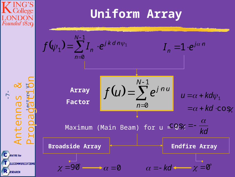
Uniform Array
1
0
N
n
unjeufArray
Factor1 kdu
1
1
01
ndkjN
nn eIf nj
n eI 1
cos kd
Maximum (Main Beam) for u = 0 :
Broadside Array Endfire Array
kd
cos
90 0 0kd
Lect
ure
VI
Ant
enna
s &
P
ropa
gatio
nA
nten
nas
&
Pro
paga
tion
-8-
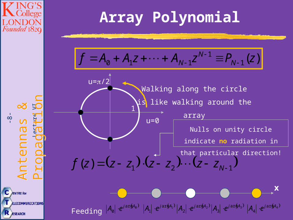
Array Polynomial
Nulls on unity circle indicate no
radiation in that particular direction!
)(11
110 zPzAzAAf NN
N
121)( Nzzzzzzzf
u=0
u=/2
1
Walking along the circle is like
walking around the array
Feeding Current:
x
0arg0
AjeA 1arg1
AjeA 2arg2
AjeA 3arg3
AjeA 4arg4
AjeA
Lect
ure
VI
Ant
enna
s &
P
ropa
gatio
nA
nten
nas
&
Pro
paga
tion
-9- Pattern Synthesis
Lect
ure
VI
Ant
enna
s &
P
ropa
gatio
nA
nten
nas
&
Pro
paga
tion
-10-
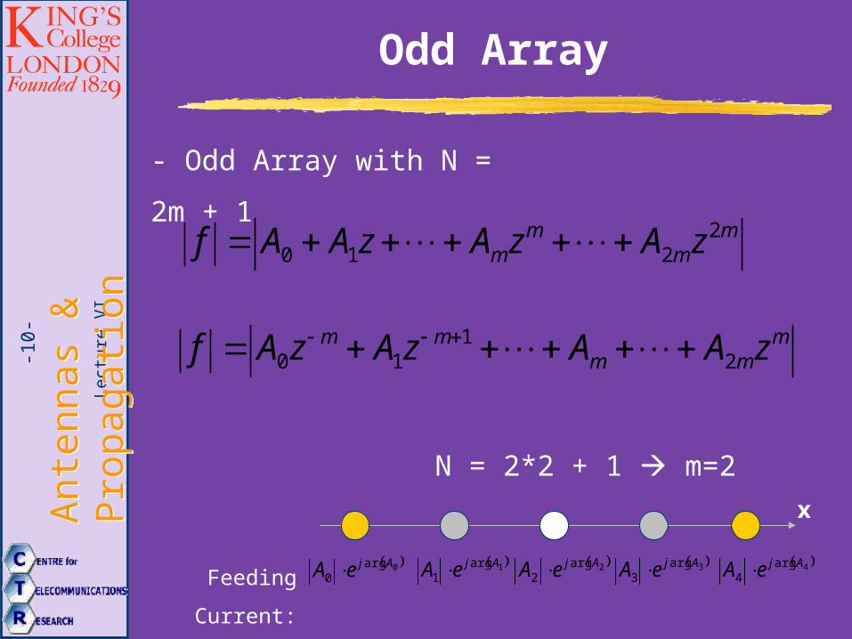
Odd Array
- Odd Array with N = 2m + 1
mm
mm zAzAzAAf 2
210
mmm
mm zAAzAzAf 21
10
Feeding Current:
x
0arg0
AjeA 1arg1
AjeA 2arg2
AjeA 3arg3
AjeA 4arg4
AjeA
N = 2*2 + 1 m=2
Lect
ure
VI
Ant
enna
s &
P
ropa
gatio
nA
nten
nas
&
Pro
paga
tion
-11-
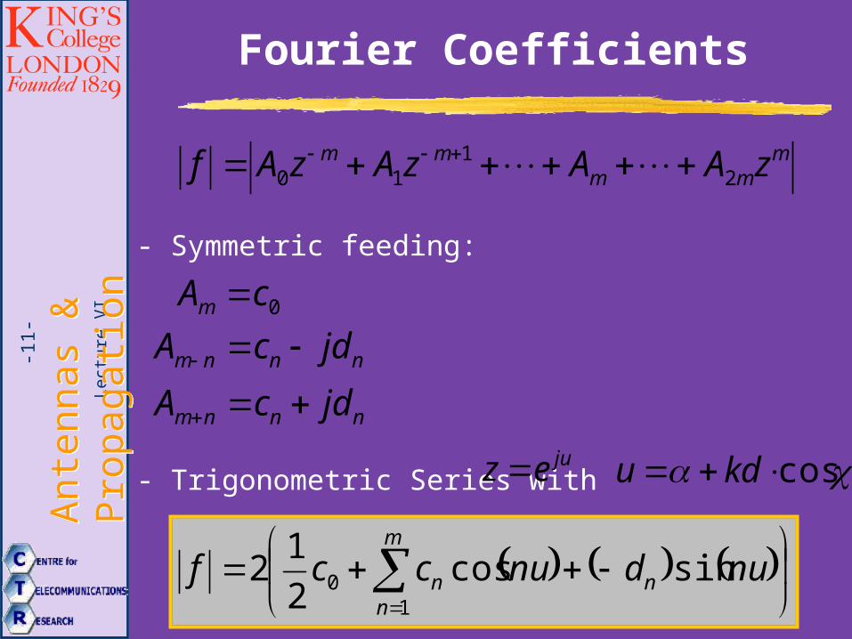
Fourier Coefficients
mmm
mm zAAzAzAf 21
10
- Symmetric feeding:
0cAm
nnnm jdcA
nnnm jdcA
- Trigonometric Series with &
m
nnn nudnuccf
10 sincos
2
12
cos kdujuez
Lect
ure
VI
Ant
enna
s &
P
ropa
gatio
nA
nten
nas
&
Pro
paga
tion
-12-
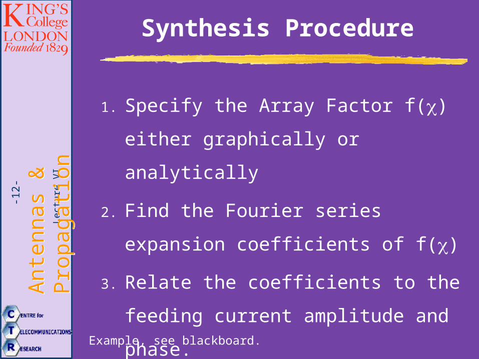
Synthesis Procedure
1. Specify the Array Factor f() either
graphically or analytically
2. Find the Fourier series expansion
coefficients of f()
3. Relate the coefficients to the feeding
current amplitude and phase.
Example, see blackboard.
Lect
ure
VI
Ant
enna
s &
P
ropa
gatio
nA
nten
nas
&
Pro
paga
tion
-13- Uda-Yagi Antenna
Lect
ure
VI
Ant
enna
s &
P
ropa
gatio
nA
nten
nas
&
Pro
paga
tion
-14-
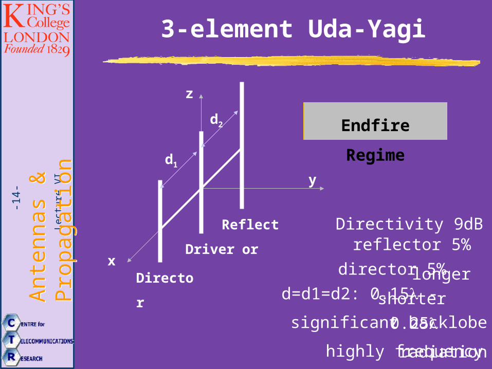
3-element Uda-Yagi
x
y
z
Driver
Endfire Regime
reflector 5% longerReflector
Director
d2
d1
director 5% shorter
d=d1=d2: 0.15 - 0.25
Directivity 9dB
highly frequency sensitive
significant backlobe radiation
Lect
ure
VI
Ant
enna
s &
P
ropa
gatio
nA
nten
nas
&
Pro
paga
tion
-15-
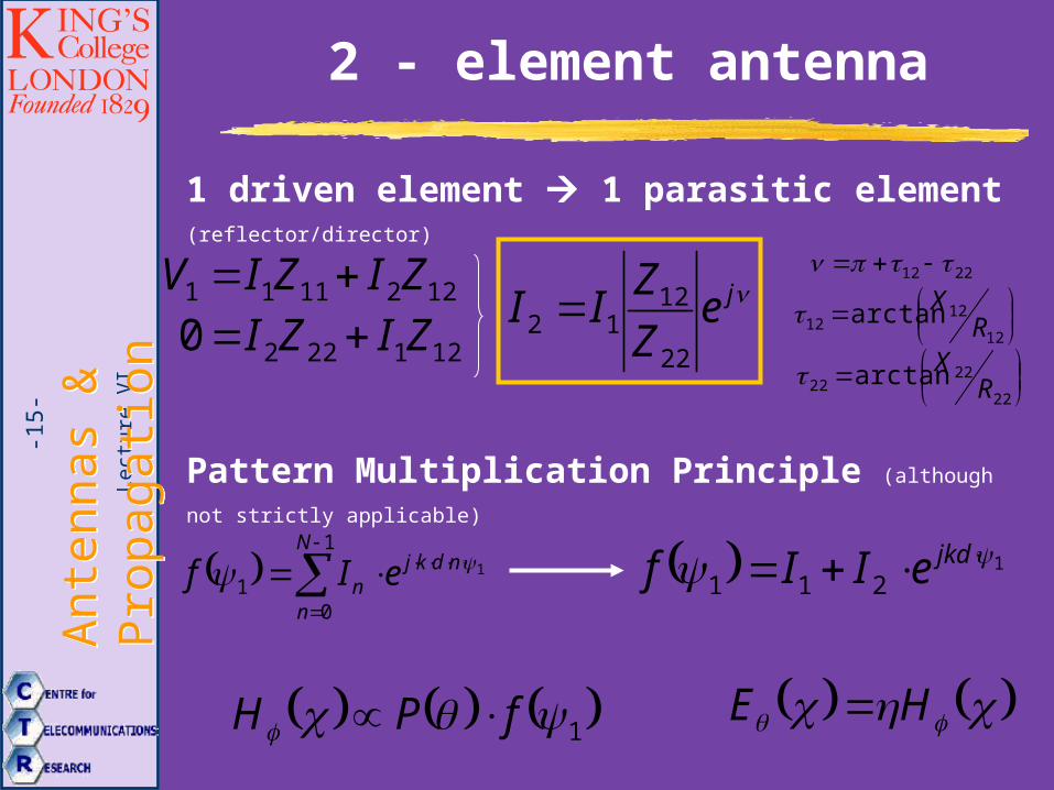
2 - element antenna
1 driven element 1 parasitic element (reflector/director)
1221111 ZIZIV
1212220 ZIZI je
Z
ZII
22
1212
2212
12
1212 arctan R
X
22
2222 arctan R
X
Pattern Multiplication Principle (although not strictly applicable)
1
1
01
ndkjN
nn eIf 1
211 jkdeIIf
1 fPH HE
Lect
ure
VI
Ant
enna
s &
P
ropa
gatio
nA
nten
nas
&
Pro
paga
tion
-16-
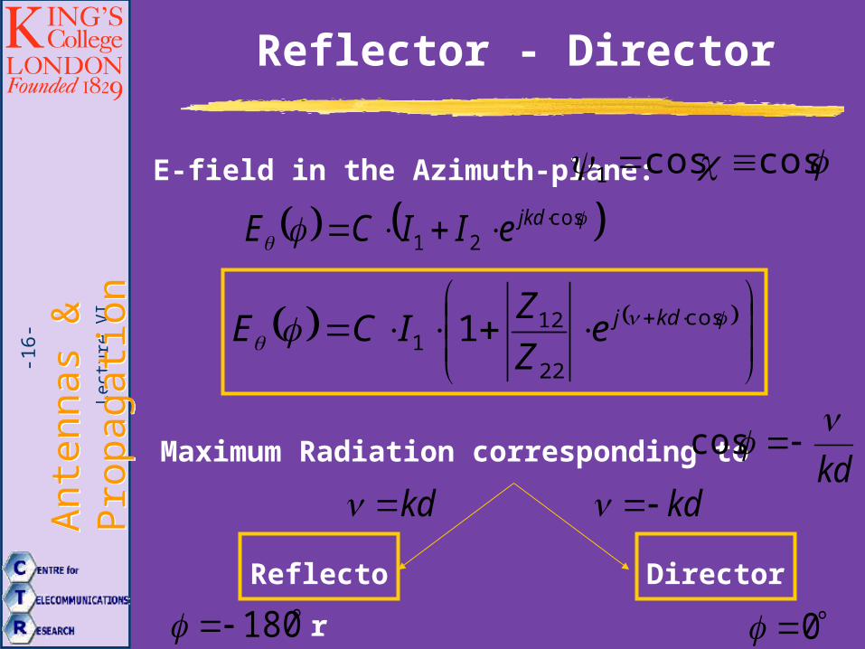
E-field in the Azimuth-plane: coscos1
cos
21 jkdeIICE
cos
22
121 1 kdje
Z
ZICE
Maximum Radiation corresponding tokd
cos
kd
Reflector
180
kd
Director
0
Reflector - Director
Lect
ure
VI
Ant
enna
s &
P
ropa
gatio
nA
nten
nas
&
Pro
paga
tion
-17-
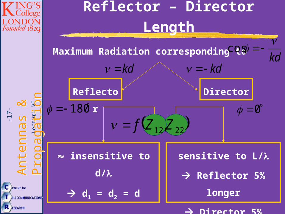
Maximum Radiation corresponding tokd
cos
kd
Reflector
180
kd
Director
0
Reflector – Director Length
2212,ZZf
insensitive to d/
d1 = d2 = d
sensitive to L/
Reflector 5% longer
Director 5% shorter
Lect
ure
VI
Ant
enna
s &
P
ropa
gatio
nA
nten
nas
&
Pro
paga
tion
-18-
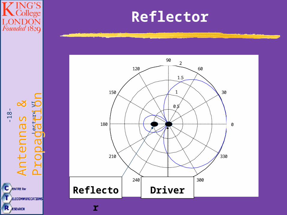
Reflector
0.5
1
1.5
2
30
210
60
240
90
270
120
300
150
330
180 0
Reflector Driver
Lect
ure
VI
Ant
enna
s &
P
ropa
gatio
nA
nten
nas
&
Pro
paga
tion
-19-
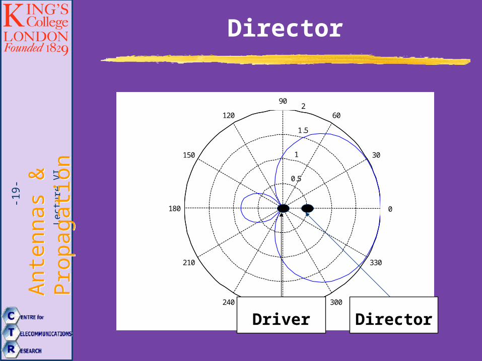
Director
0.5
1
1.5
2
30
210
60
240
90
270
120
300
150
330
180 0
DirectorDriver
Lect
ure
VI
Ant
enna
s &
P
ropa
gatio
nA
nten
nas
&
Pro
paga
tion
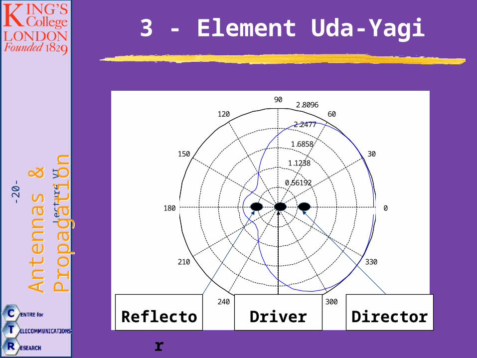
-20-
0.56192
1.1238
1.6858
2.2477
2.8096
30
210
60
240
90
270
120
300
150
330
180 0
3 - Element Uda-Yagi
DirectorDriverReflector
Lect
ure
VI
Ant
enna
s &
P
ropa
gatio
nA
nten
nas
&
Pro
paga
tion
-21-
Application of Uda-Yagi
The Uda-Yagi is the most popular receiving
antenna in VHF-UHF due to:
1. Simple feeding system design
2. Low cost
3. Light weight
4. Relatively high gain
Lect
ure
VI
Ant
enna
s &
P
ropa
gatio
nA
nten
nas
&
Pro
paga
tion
-22-
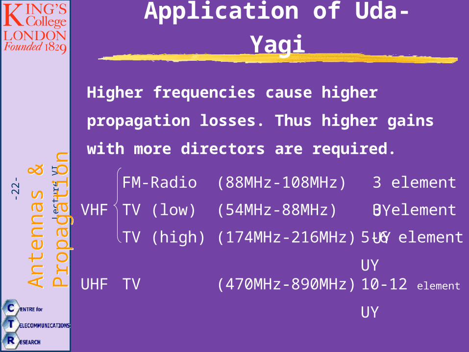
Application of Uda-Yagi
Higher frequencies cause higher propagation
losses. Thus higher gains with more directors are
required.
FM-Radio (88MHz-108MHz) 3 element UY
TV (low) (54MHz-88MHz) 3 element UY
TV (high) (174MHz-216MHz) 5-6 element UY
TV (470MHz-890MHz) 10-12 element UY
VHF
UHF
Lect
ure
VI
Ant
enna
s &
P
ropa
gatio
nA
nten
nas
&
Pro
paga
tion
-23-
Practical Design Criteria
1. Closer spacing between elements results in higher
front-to-back ratio with a broader main beam.
2. Wider spacing yields the opposite.
3. Wider spacing has a greater bandwidth.
4. Uda-Yagi has broader bandwidth if reflector is longer
than optimum and director shorter.
5. Folded dipole as driven element to gain more radiation
power and broader bandwidth.
6. To broaden bandwidth reflector should be replaced by
flat sheet (or wire grid).
7. Tilted fan dipole for broader bandwidth.
Lect
ure
VI
Ant
enna
s &
P
ropa
gatio
nA
nten
nas
&
Pro
paga
tion
-24-
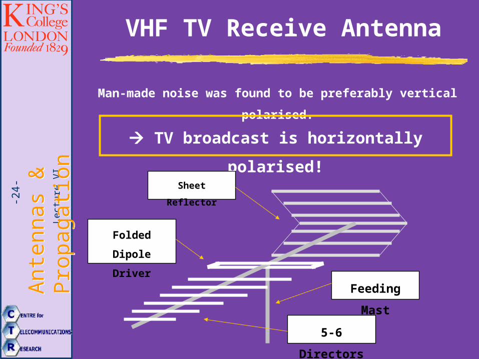
VHF TV Receive Antenna
Man-made noise was found to be preferably vertical polarised.
TV broadcast is horizontally polarised!
5-6 Directors
Folded Dipole
Driver
Sheet Reflector
Feeding Mast

Lect
ure
VI
Ant
enna
s &
P
ropa
gatio
nA
nten
nas
&
Pro
paga
tion
-25- Corner Reflector
Lect
ure
VI
Ant
enna
s &
P
ropa
gatio
nA
nten
nas
&
Pro
paga
tion
-26-
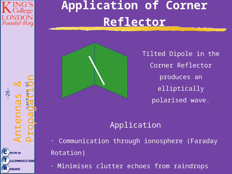
Application of Corner Reflector
Tilted Dipole in the Corner
Reflector produces an
elliptically polarised wave.
Application
- Communication through ionosphere (Faraday Rotation)
- Minimises clutter echoes from raindrops
Lect
ure
VI
Ant
enna
s &
P
ropa
gatio
nA
nten
nas
&
Pro
paga
tion
-27- Turnstile Antenna
Lect
ure
VI
Ant
enna
s &
P
ropa
gatio
nA
nten
nas
&
Pro
paga
tion
-28-
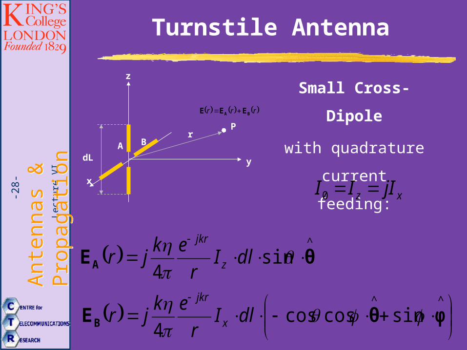
Turnstile Antenna
Small Cross-Dipole
with quadrature
current feeding:
x
r
y
z
P
dLA B
^
sin4
θEA
dlIr
ekjr z
jkr
^^
sincoscos4
φθEB
dlIr
ekjr x
jkr
xz jIII 0
rrr BA EEE
Lect
ure
VI
Ant
enna
s &
P
ropa
gatio
nA
nten
nas
&
Pro
paga
tion
-29-
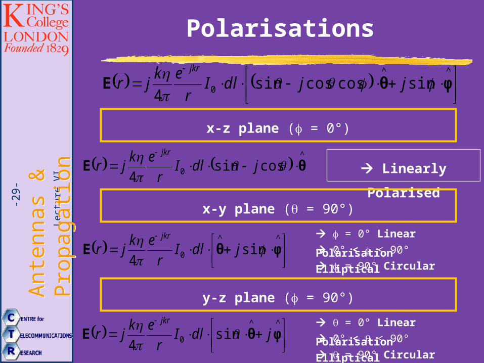
Polarisations
^^
0 sincoscossin4
φθE
jjdlIr
ekjr
jkr
x-z plane ( = 0°)
^
0 cossin4
θE
jdlIr
ekjr
jkr
Linearly Polarised
x-y plane ( = 90°)
^^
0 sin4
φθE
jdlIr
ekjr
jkr = 0° Linear Polarisation
0° < < 90° Elliptical
= 90° Circular
y-z plane ( = 90°)
^^
0 sin4
φθE jdlIr
ekjr
jkr
= 0° Linear Polarisation
0° < < 90° Elliptical
= 90° Circular
Lect
ure
VI
Ant
enna
s &
P
ropa
gatio
nA
nten
nas
&
Pro
paga
tion
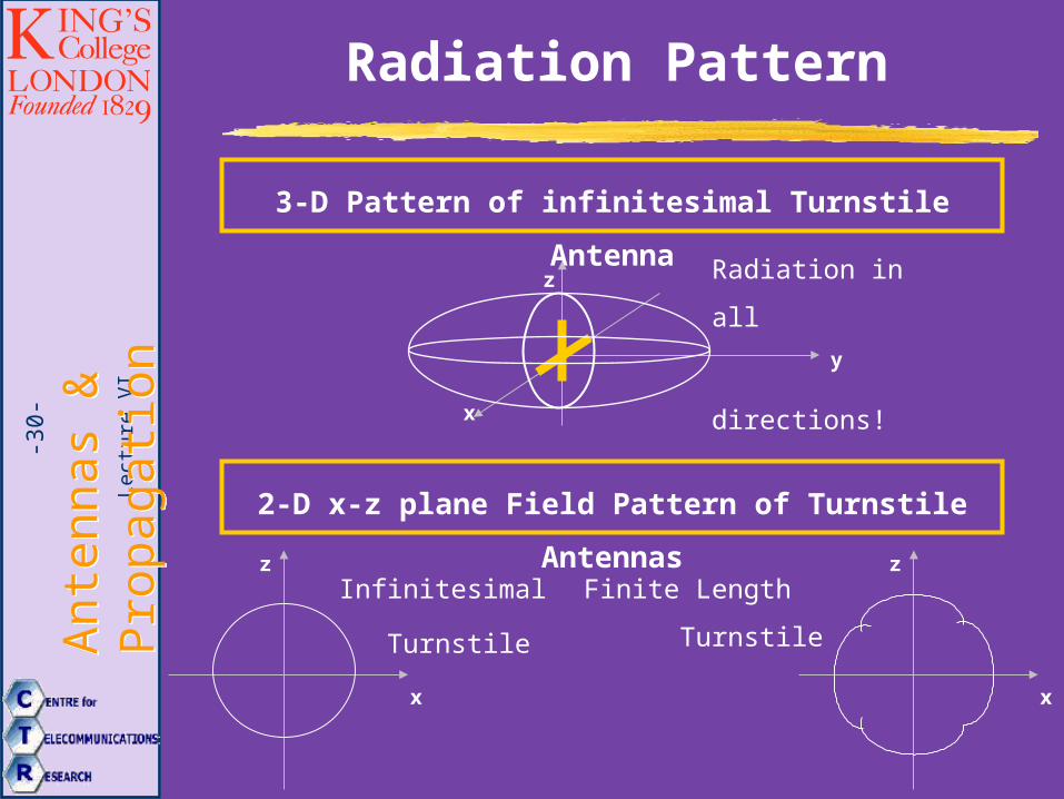
-30-
Radiation Pattern
3-D Pattern of infinitesimal Turnstile Antenna
x
y
z
2-D x-z plane Field Pattern of Turnstile Antennas
x
z
x
zInfinitesimal
Turnstile
Finite Length
Turnstile
Radiation in all
directions!
Lect
ure
VI
Ant
enna
s &
P
ropa
gatio
nA
nten
nas
&
Pro
paga
tion
-31-
Application
1. Circular polarisation in Broadside direction:
Satellite Communication
Radar Application
2. Communication of unstabilised space-crafts
due to radiation property in all directions.
3. In x-z plane almost circular radiation pattern:
TV-broadcast transmit antenna
Lect
ure
VI
Ant
enna
s &
P
ropa
gatio
nA
nten
nas
&
Pro
paga
tion
-32- Loop Antenna
Lect
ure
VI
Ant
enna
s &
P
ropa
gatio
nA
nten
nas
&
Pro
paga
tion
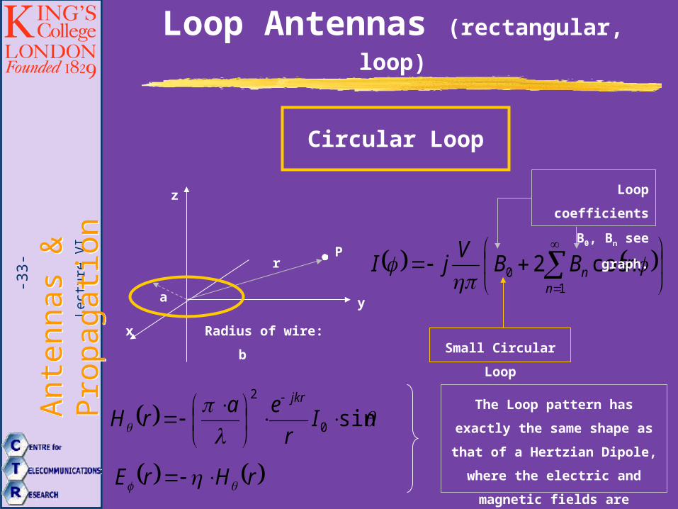
-33-
Loop Antennas (rectangular, loop)
Circular Loop
x
r
y
z
P
a
10 cos2
nn nBB
VjI
Radius of wire: b
Loop coefficients
B0, Bn see graph.
Small Circular Loop
sin0
2
Ir
earH
jkr
rHrE
The Loop pattern has exactly the
same shape as that of a Hertzian
Dipole, where the electric and
magnetic fields are interchanged.
Lect
ure
VI
Ant
enna
s &
P
ropa
gatio
nA
nten
nas
&
Pro
paga
tion
-34-
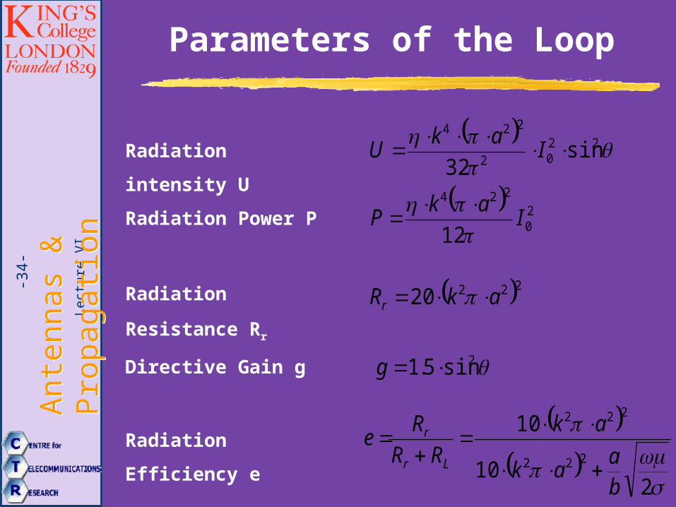
Parameters of the Loop
22
02
224
sin32
Iak
URadiation intensity U
20
224
12I
akP
Radiation Power P
22220 akRr Radiation Resistance Rr
2sin5.1 gDirective Gain g
210
10
222
222
ba
ak
ak
RR
Re
Lr
r
Radiation Efficiency e
Lect
ure
VI
Ant
enna
s &
P
ropa
gatio
nA
nten
nas
&
Pro
paga
tion
-35-
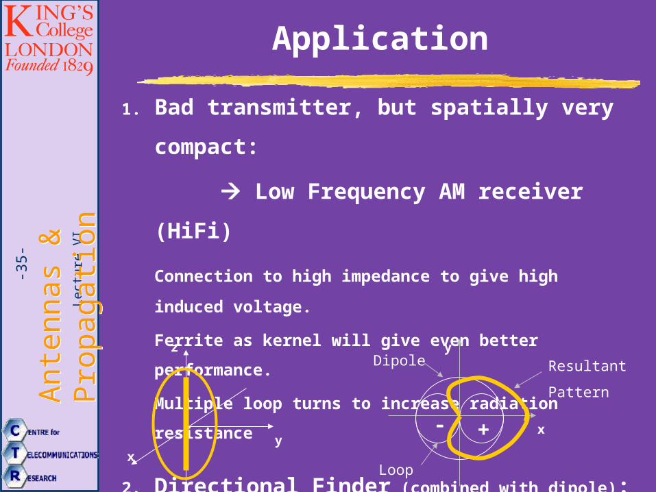
Application
1. Bad transmitter, but spatially very compact:
Low Frequency AM receiver (HiFi)
Connection to high impedance to give high induced voltage.
Ferrite as kernel will give even better performance.
Multiple loop turns to increase radiation resistance
2. Directional Finder (combined with dipole):
xy
z
x
y
- +
Dipole
Loop
Resultant
Pattern
Lect
ure
VI
Ant
enna
s &
P
ropa
gatio
nA
nten
nas
&
Pro
paga
tion
-36- Helical Antenna
Lect
ure
VI
Ant
enna
s &
P
ropa
gatio
nA
nten
nas
&
Pro
paga
tion
-37-
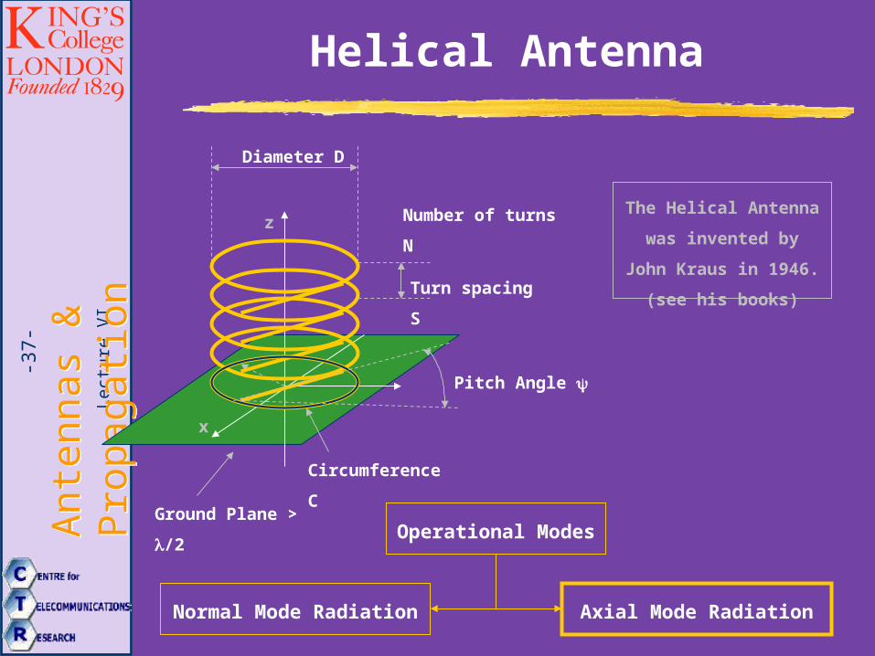
Helical Antenna
x
zThe Helical Antenna was
invented by John Kraus
in 1946. (see his books)
Diameter D
Turn spacing S
Circumference C
Pitch Angle
Operational Modes
Normal Mode Radiation Axial Mode Radiation
Ground Plane > /2
Number of turns N
Lect
ure
VI
Ant
enna
s &
P
ropa
gatio
nA
nten
nas
&
Pro
paga
tion
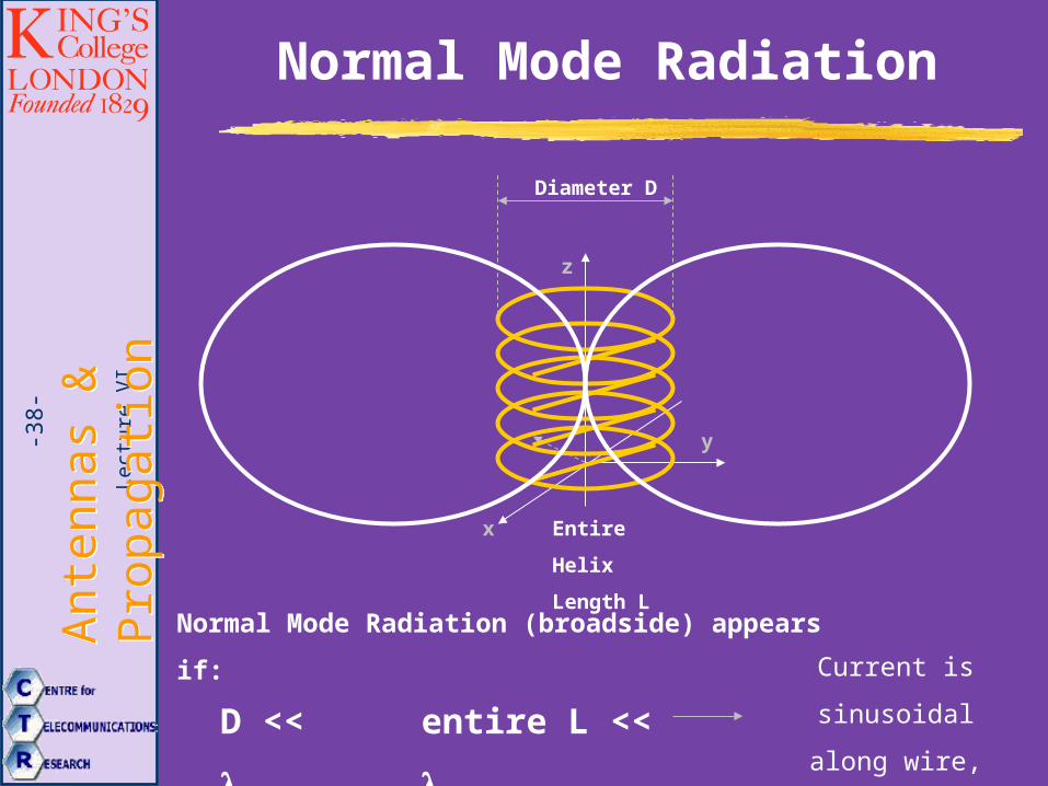
-38-
Normal Mode Radiation
x
z
Diameter D
Entire Helix
Length L
y
Normal Mode Radiation (broadside) appears if:
D << entire L <<
Current is sinusoidal
along wire, thus
radiation from a loop
Lect
ure
VI
Ant
enna
s &
P
ropa
gatio
nA
nten
nas
&
Pro
paga
tion
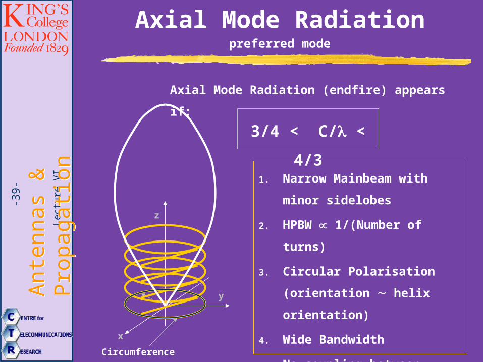
-39-
Axial Mode Radiation preferred mode
x
z
y
Circumference C
Axial Mode Radiation (endfire) appears if:
3/4 < C/ < 4/3
1. Narrow Mainbeam with minor
sidelobes
2. HPBW 1/(Number of turns)
3. Circular Polarisation
(orientation helix
orientation)
4. Wide Bandwidth
5. No coupling between elements
6. Supergain Endfire Array
Lect
ure
VI
Ant
enna
s &
P
ropa
gatio
nA
nten
nas
&
Pro
paga
tion
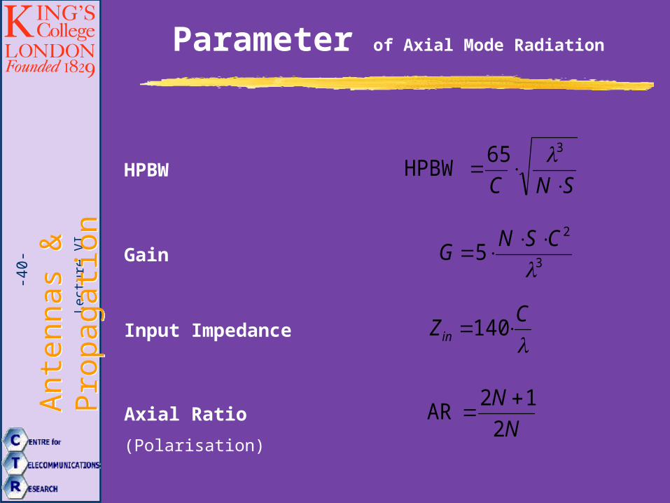
-40-
Parameter of Axial Mode Radiation
SNC
365HPBW
HPBW
3
2
5
CSNG
Gain
C
Zin 140Input Impedance
N
N
2
12AR
Axial Ratio (Polarisation)
Lect
ure
VI
Ant
enna
s &
P
ropa
gatio
nA
nten
nas
&
Pro
paga
tion
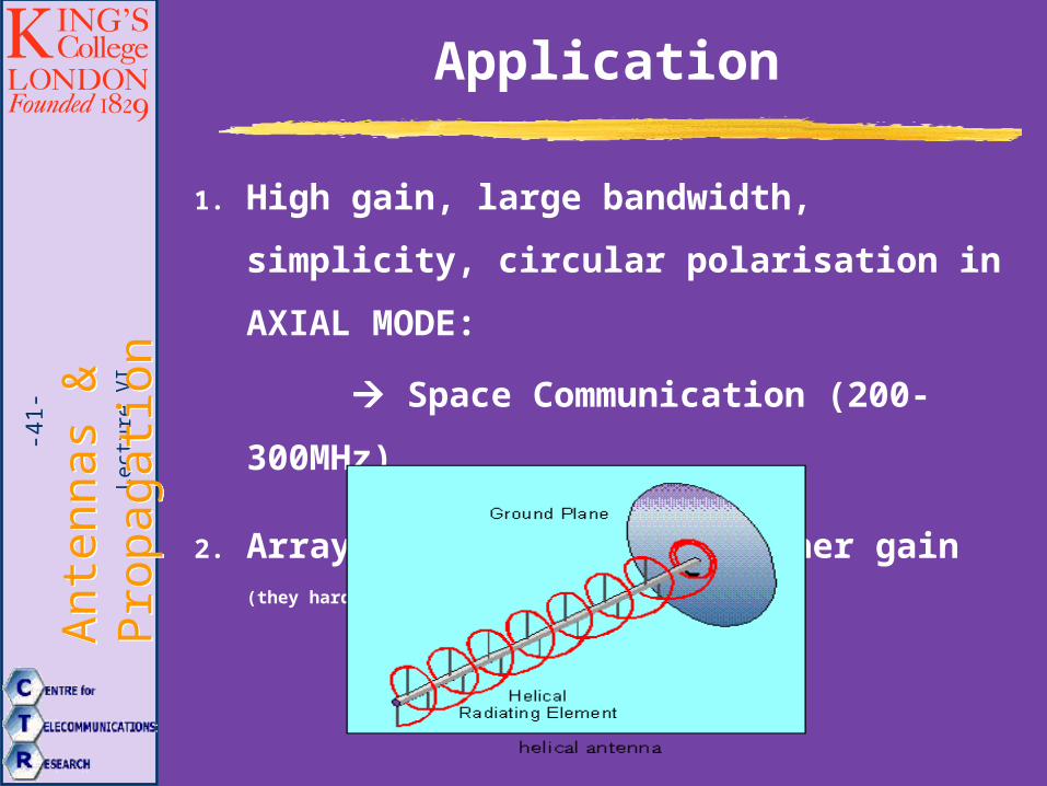
-41-
Application
1. High gain, large bandwidth, simplicity,
circular polarisation in AXIAL MODE:
Space Communication (200-300MHz)
2. Arrays of Helixes with higher gain (they hardly couple!)
Lect
ure
VI
Ant
enna
s &
P
ropa
gatio
nA
nten
nas
&
Pro
paga
tion
-42-
Quadrifilar Helix
Antenna
Lect
ure
VI
Ant
enna
s &
P
ropa
gatio
nA
nten
nas
&
Pro
paga
tion
-43-
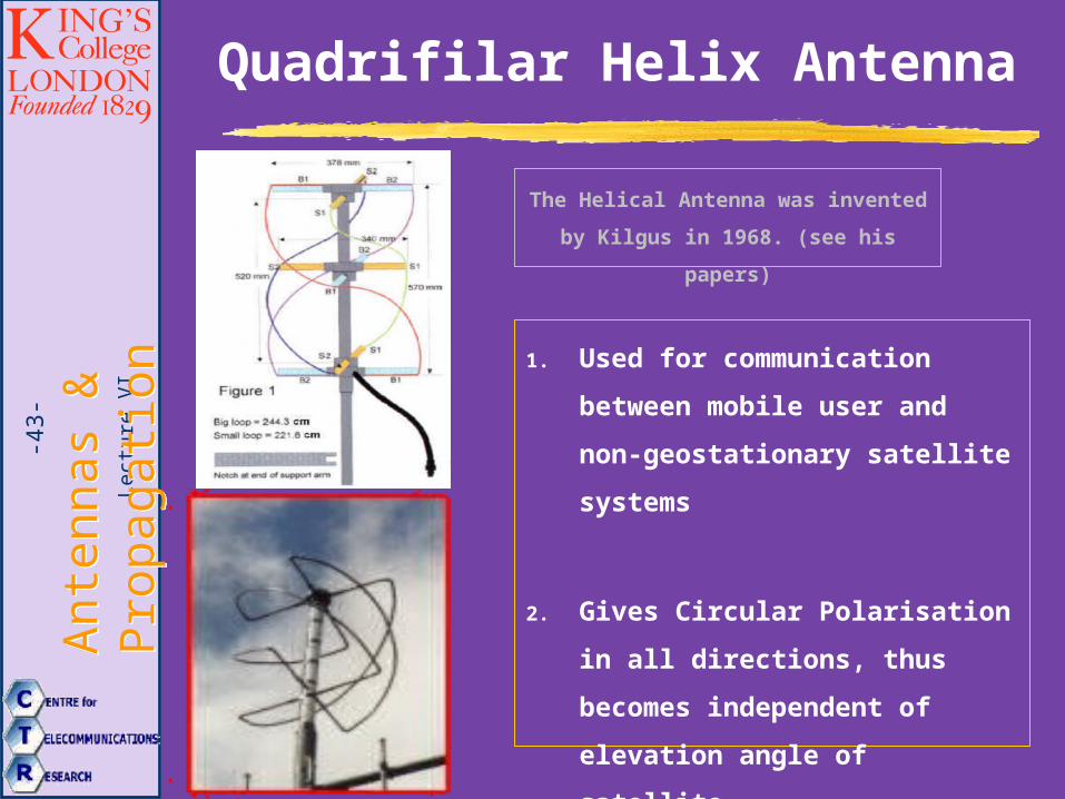
Quadrifilar Helix Antenna
The Helical Antenna was invented by
Kilgus in 1968. (see his papers)
1. Used for communication between
mobile user and non-
geostationary satellite systems
2. Gives Circular Polarisation in all
directions, thus becomes
independent of elevation angle of
satellite.