Lecture 24
22
1 CSE370, Lecture 24 Lecture 24 Logistics HW7 back today Midterm2 back today (Average 80/100) Solution on-line this PM HW8 due Wednesday Ant extra credit due Friday Final exam, Wednesday March 18, 2:30-4:20 pm here Review session Monday, March 16, 4:30 pm, here Last lecture State encoding One-hot encoding Output encoding State partitioning Today Encoding & Partitioning examples
-
Upload
giacomo-chapman -
Category
Documents
-
view
28 -
download
2
description
Lecture 24. Logistics HW7 back today Midterm2 back today (Average 80/100) Solution on-line this PM HW8 due Wednesday Ant extra credit due Friday Final exam, Wednesday March 18, 2:30-4:20 pm here Review session Monday, March 16, 4:30 pm, here Last lecture State encoding - PowerPoint PPT Presentation
Transcript of Lecture 24
1CSE370, Lecture 24
Lecture 24
Logistics HW7 back today Midterm2 back today (Average 80/100)
Solution on-line this PM HW8 due Wednesday Ant extra credit due Friday Final exam, Wednesday March 18, 2:30-4:20 pm here
Review session Monday, March 16, 4:30 pm, here
Last lecture State encoding
One-hot encoding Output encoding
State partitioning
Today Encoding & Partitioning examples
2CSE370, Lecture 24
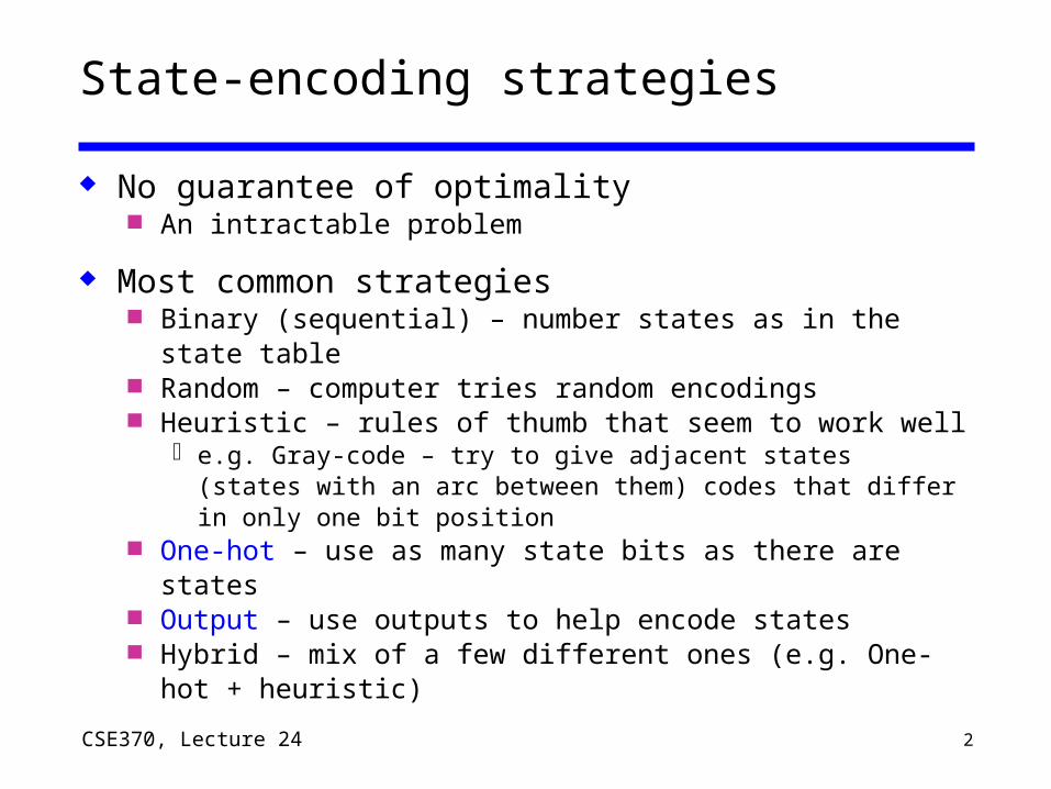
State-encoding strategies
No guarantee of optimality An intractable problem
Most common strategies Binary (sequential) – number states as in the state
table Random – computer tries random encodings Heuristic – rules of thumb that seem to work well
e.g. Gray-code – try to give adjacent states (states with an arc between them) codes that differ in only one bit position
One-hot – use as many state bits as there are states Output – use outputs to help encode states Hybrid – mix of a few different ones (e.g. One-hot +
heuristic)
3CSE370, Lecture 24
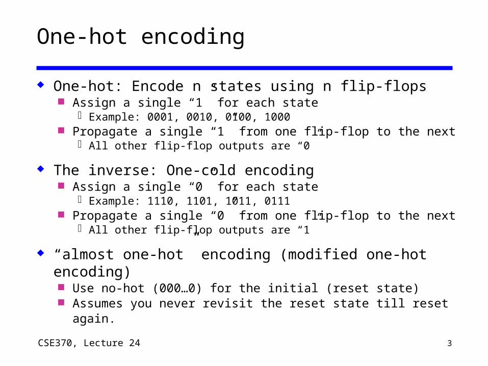
One-hot encoding
One-hot: Encode n states using n flip-flops Assign a single “1” for each state
Example: 0001, 0010, 0100, 1000 Propagate a single “1” from one flip-flop to the next
All other flip-flop outputs are “0”
The inverse: One-cold encoding Assign a single “0” for each state
Example: 1110, 1101, 1011, 0111 Propagate a single “0” from one flip-flop to the next
All other flip-flop outputs are “1”
“almost one-hot” encoding (modified one-hot encoding) Use no-hot (000…0) for the initial (reset state) Assumes you never revisit the reset state till reset again.

4CSE370, Lecture 24
Another Encoding Example: Digital combination lock
An output-encoded FSM Punch in 3 values in sequence and the door opens If there is an error the lock must be reset After the door opens the lock must be reset Inputs: sequence of number values, reset Outputs: door open/close
resetvalue
open/closed
new
clock

5CSE370, Lecture 24
Separate data path and control
Design datapath first After the state diagram Before the state
encoding
Control has 2 outputs Mux control to datapath Lock open/closed
reset
open/closed
newC1 C2 C3
comparatorvalueequal
multiplexer
controller
mux control
clock4
4 4 4
4
6CSE370, Lecture 24
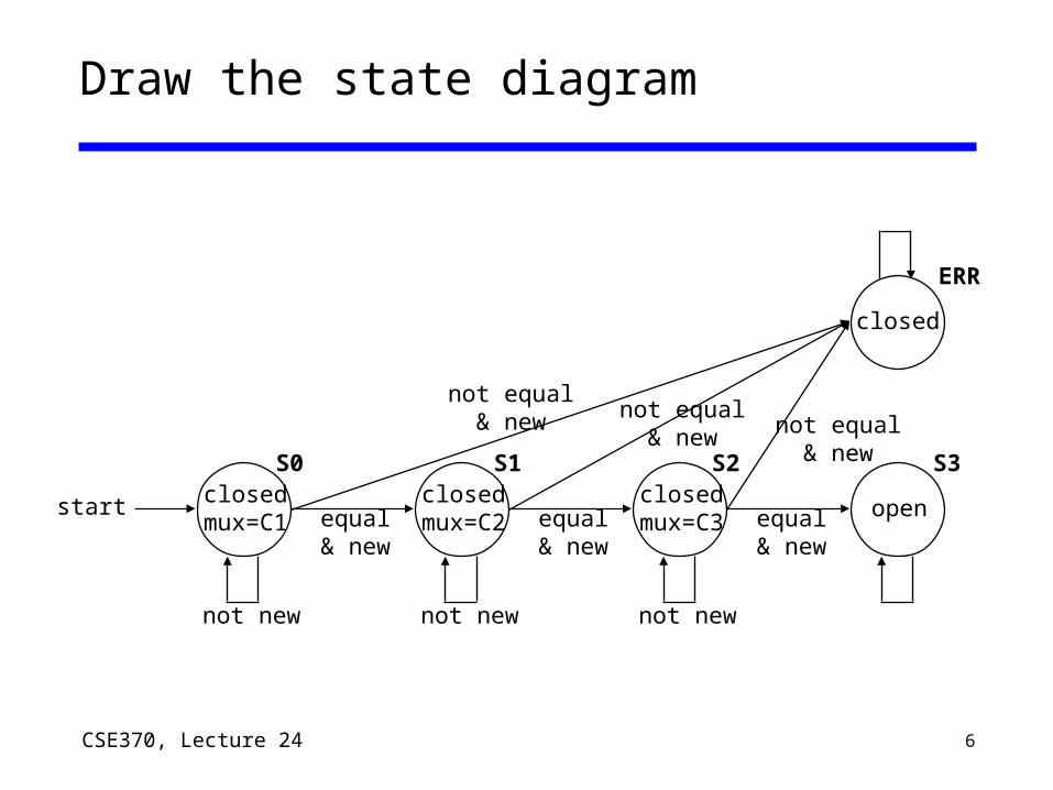
Draw the state diagram
closed
closedmux=C1
start equal& new
not equal& new not equal
& new not equal& new
not newnot newnot new
S0 S1 S2 S3
ERR
closedmux=C2 equal
& new
closedmux=C3 equal
& new
open
7CSE370, Lecture 24
C1 C2 C3
comparatorequal
multiplexer
mux control
4
4 4 4
4value
C1i C2i C3i
mux control
valuei
equal
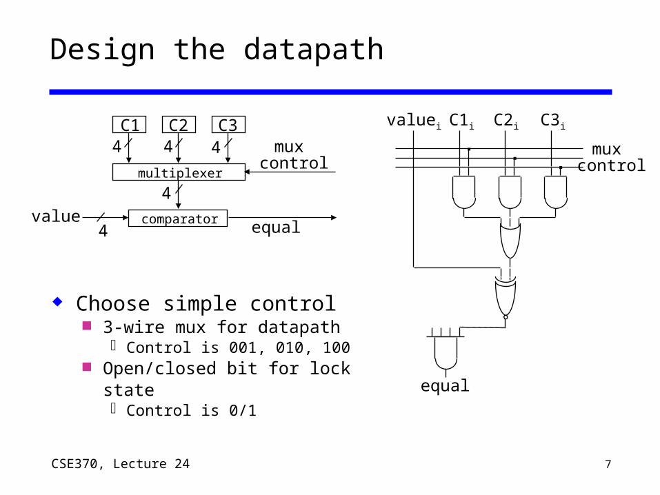
Design the datapath
Choose simple control 3-wire mux for datapath
Control is 001, 010, 100 Open/closed bit for lock
state Control is 0/1
8CSE370, Lecture 24
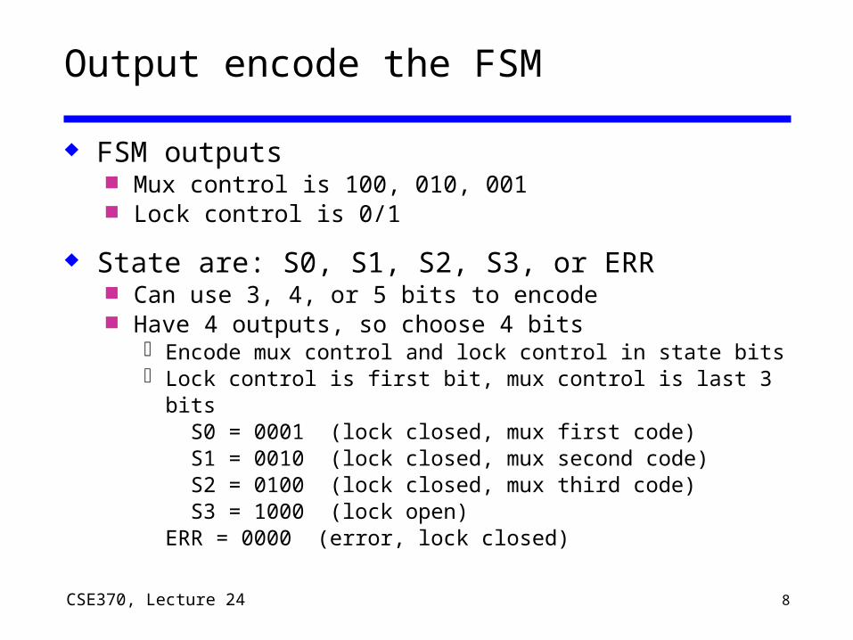
Output encode the FSM
FSM outputs Mux control is 100, 010, 001 Lock control is 0/1
State are: S0, S1, S2, S3, or ERR Can use 3, 4, or 5 bits to encode Have 4 outputs, so choose 4 bits
Encode mux control and lock control in state bits Lock control is first bit, mux control is last 3 bits
S0 = 0001 (lock closed, mux first code) S1 = 0010 (lock closed, mux second code) S2 = 0100 (lock closed, mux third code) S3 = 1000 (lock open)ERR = 0000 (error, lock closed)
9CSE370, Lecture 24
FSM has 4 state bits and 2 inputs...
Output encoded! Outputs and state bits are the same
How do we minimize the logic? FSM has 4 state bits and 2 inputs (equal, new) 6-variable K-map for all five states?
Way too complicated
Notice the state assignment is close to one-hot ERR state (0000) is only deviation Is there a clever design we can use?
10CSE370, Lecture 24
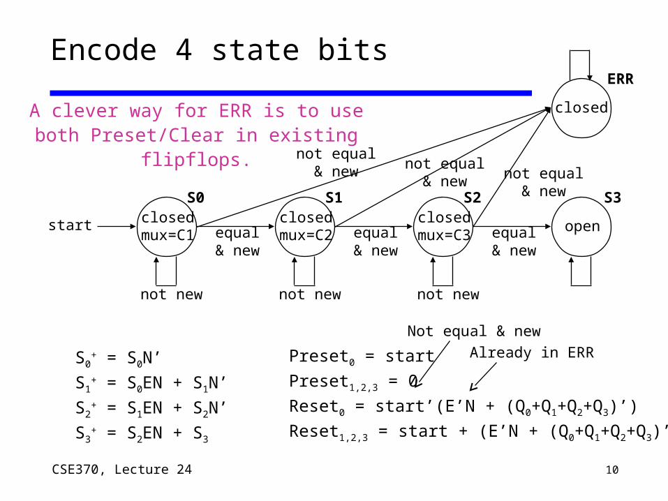
Encode 4 state bits
closed
closedmux=C1
start equal& new
not equal& new not equal
& new not equal& new
not newnot newnot new
S0 S1 S2 S3
ERR
closedmux=C2 equal
& new
closedmux=C3 equal
& new
open
S0+ = S0N’
S1+ = S0EN + S1N’
S2+ = S1EN + S2N’
S3+ = S2EN + S3
A clever way for ERR is to use both Preset/Clear in existing flipflops.
Preset0 = start
Preset1,2,3 = 0
Reset0 = start’(E’N + (Q0+Q1+Q2+Q3)’)
Reset1,2,3 = start + (E’N + (Q0+Q1+Q2+Q3)’)
Not equal & newAlready in ERR
11CSE370, Lecture 24
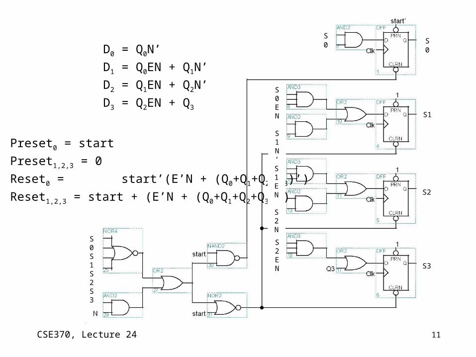
D0 = Q0N’
D1 = Q0EN + Q1N’
D2 = Q1EN + Q2N’
D3 = Q2EN + Q3
Preset0 = start
Preset1,2,3 = 0
Reset0 = start’(E’N + (Q0+Q1+Q2+Q3)’)
Reset1,2,3 = start + (E’N + (Q0+Q1+Q2+Q3)’)
S0
S2
S1
S3
S0
S0 E N
S1N’
S1 E N
S2N’
S2 E N
S0 S1S2S3

12CSE370, Lecture 24
C1
C2
C5•S2
S6
S4
S5SB
C1•S1
C3•S2+C4•S3
(C1•S1+C3•S2+C4•S3+C5•S2)’
C4
S1
S3
S2 SA
C2•S6
C3+C5
(C2•S6)’
State Partitioning
Add idles states to handoff control between machines
C1
C2
C3
C4 C5
S1
S3
S2
S6
S4
S5

13CSE370, Lecture 24
highway
farm road
car sensors
Example: Traffic light controller
Highway/farm road intersection
14CSE370, Lecture 24
Example: traffic light controller
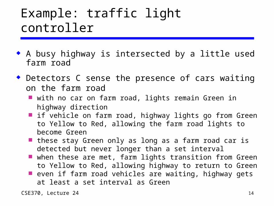
A busy highway is intersected by a little used farm road
Detectors C sense the presence of cars waiting on the farm road with no car on farm road, lights remain Green in highway
direction if vehicle on farm road, highway lights go from Green to
Yellow to Red, allowing the farm road lights to become Green these stay Green only as long as a farm road car is detected
but never longer than a set interval when these are met, farm lights transition from Green to
Yellow to Red, allowing highway to return to Green even if farm road vehicles are waiting, highway gets at least a
set interval as Green

15CSE370, Lecture 24
Example: traffic light controller
Assume you have an interval timer that in response to a set (ST) signal generates both: a short time pulse (TS) and a long time pulse (TL)
TS is to be used for timing yellow lights and TL for green lights
Interval Timer
Traffic Light Controller
ST
TL
TS
ST
TS
TL
short
long

16CSE370, Lecture 24
Example: traffic light controller
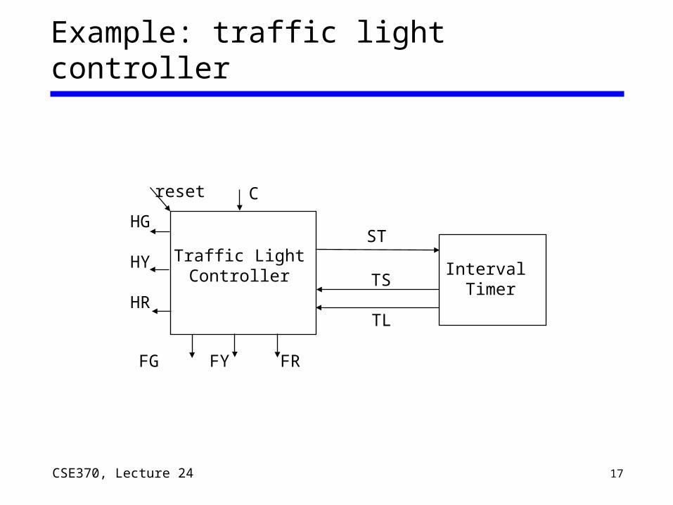
InputsDescription reset place FSM in initial state C detect vehicle on the farm road TS short time interval expiredTL long time interval expired
Outputs DescriptionHG, HY, HR assert green/yellow/red highway lights
FG, FY, FR assert green/yellow/red farm road lightsST start timing a short or long interval
States – some light configurations imply others
State DescriptionHG highway green (farm road red)HY highway yellow (farm road red)FG farm road green (highway red)FY farm road yellow (highway red)
17CSE370, Lecture 24
HG
HY
HR
Example: traffic light controller
Interval Timer
Traffic Light Controller
ST
TL
TS
Creset
FG FY FR

18CSE370, Lecture 24
Example: traffic light controller
State diagram
Reset
TS'
TS / ST
(TL•C)'
TL•C / ST
TS'
TS / ST
(TL+C')'
TL+C' / ST
HG
FG
FYHY
Outputs not shown: FR=HG+HY HR=FG+FY

19CSE370, Lecture 24
Example: State Partitioning
TS / ST
Reset
TL•C / ST
TS' HY
(TL•C)'
HG
TS / ST
(TL+C')'
TL+C' / STFG
FY TS'

20CSE370, Lecture 24
State partitioning for traffic light controller
Reset
(TL+C')'
TL+C' / STFG
FY
TL•C / ST
TS' HY
(TL•C)'
HG
TS / ST
TS / STHR
TS•FY
TS•HY
(TS•HY)’
(TS•FY)’
FR
Reset
Add idle statesAdd return arcs
Label idle wait loops
TS'
21CSE370, Lecture 24
Minimize communication between partitions
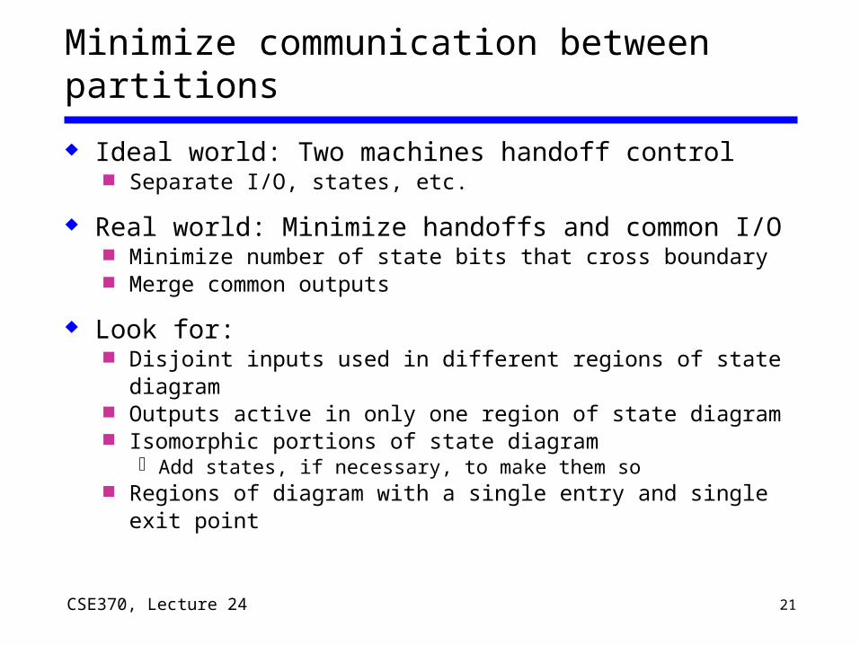
Ideal world: Two machines handoff control Separate I/O, states, etc.
Real world: Minimize handoffs and common I/O Minimize number of state bits that cross boundary Merge common outputs
Look for: Disjoint inputs used in different regions of state
diagram Outputs active in only one region of state diagram Isomorphic portions of state diagram
Add states, if necessary, to make them so Regions of diagram with a single entry and single exit
point

22CSE370, Lecture 24
FSM design: A multi-step process
1. Understand the problem– State diagram and state-transition table
2. Determine the machine’s states– Consider missing transitions: Will the machine start?– Minimize the state diagram: Reuse states where possible
3. Encode the states – Encode states, outputs with a reasonable encoding choice– Consider the implementation target
4. Design the next-state logic– Minimize the combinational logic– Choices made in steps 2 & 3 affect the logic complexity
5. Implement the FSM