Lecture 23: 3-D Pose Object Recognition
36
Lecture 23: 3-D Pose Object Recognition
Transcript of Lecture 23: 3-D Pose Object Recognition
Lecture 23: 3-D PoseObject Recognition
The 3-D Pose problem• We know an object’s model• We see a single image of this object• Goal: Find the camera position that resulted in this pose.• Subsequent goal: Use this for object recognition

How Do We See Objects in Depth?
• Stereo– Use differences between images in our left and right
eye– How much is this difference for a car at 100 m?
• Move our head sideways– Or, the scene is moving– Or we are moving in a car
• We know the size and shape of objects– Traffic lights, car headlights and taillights
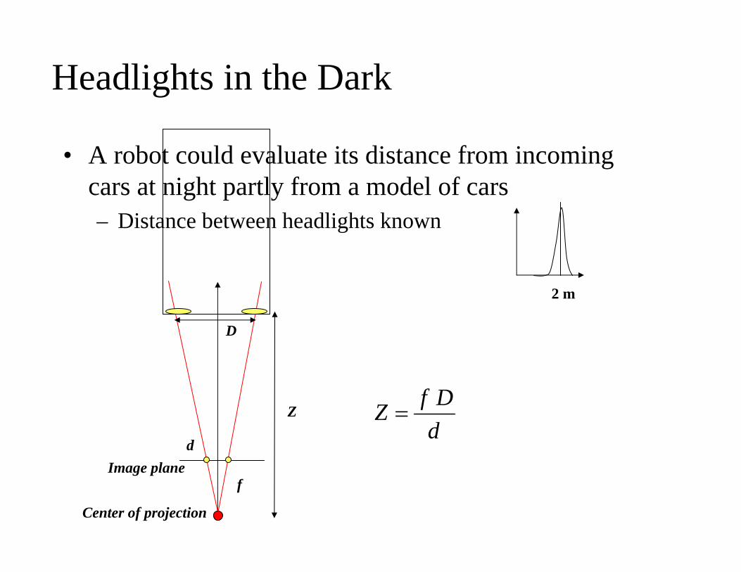
Headlights in the Dark
• A robot could evaluate its distance from incoming cars at night partly from a model of cars– Distance between headlights known
Image plane
Center of projection
D
f
Z
ddDfZ =
2 m
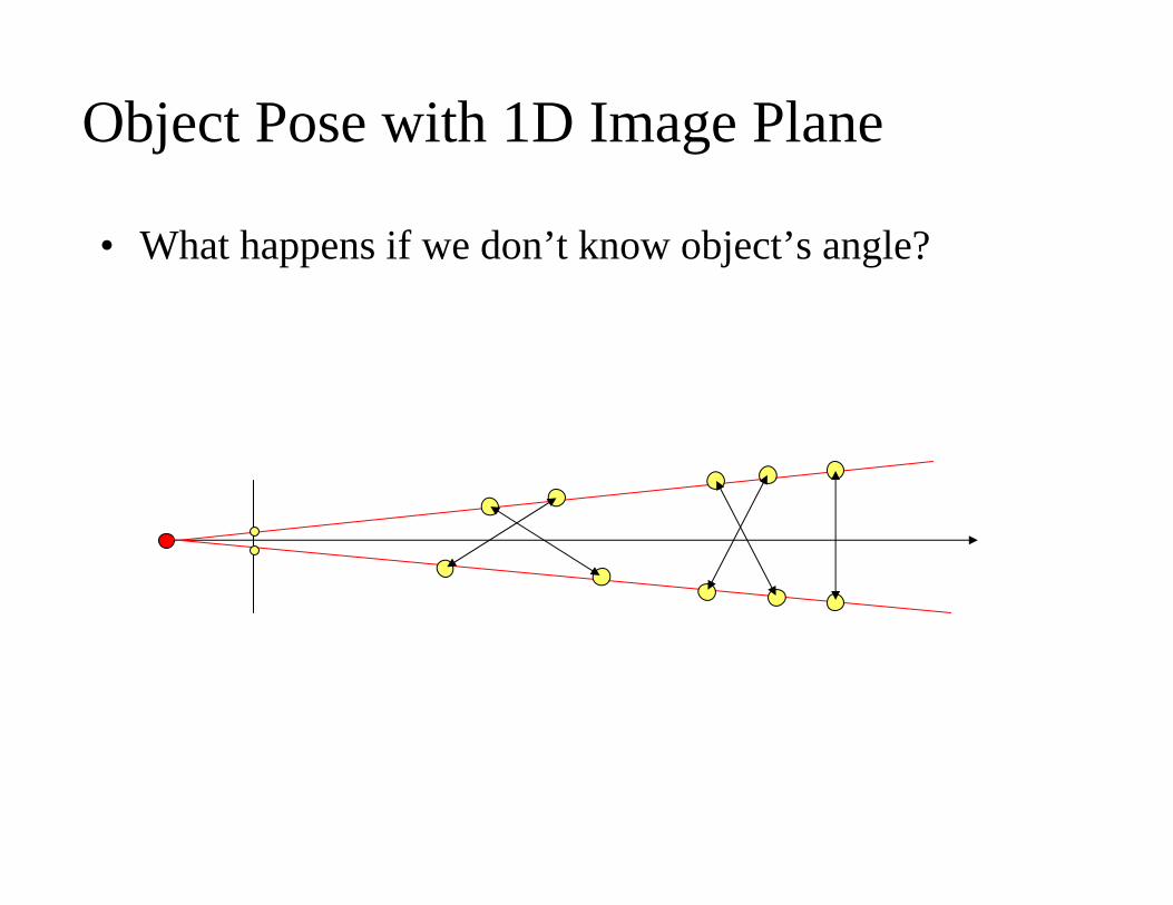
Object Pose with 1D Image Plane
• What happens if we don’t know object’s angle?
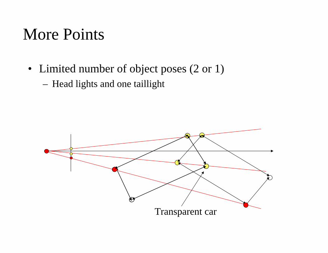
More Points
• Limited number of object poses (2 or 1)– Head lights and one taillight
Transparent car
Correspondence Problem• When we know correspondences (i.e. matchings), pose is
easier to find• When we know the pose, correspondences are easier to
find.• But we need to find both at the same time• We follow the usual E-M strategy that we know
correspondences and describe how to solve the pose given n corresponding points in image and object– Perspective n-Point Problem
• Then we explore what to do when we don’t know correspondences
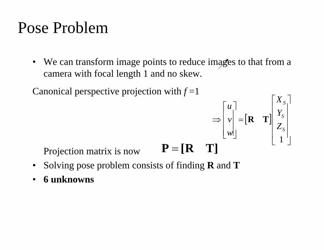
Pose Problem
• We can transform image points to reduce images to that from a camera with focal length 1 and no skew.
Projection matrix is now• Solving pose problem consists of finding R and T• 6 unknowns
[ ]⎥⎥⎥⎥
⎦
⎤
⎢⎢⎢⎢
⎣
⎡
=⎥⎥⎥
⎦
⎤
⎢⎢⎢
⎣
⎡⇒
1S
S
S
ZYX
wvu
TR
]TR[P =
Canonical perspective projection with f =1
Pose solution• Can solve it using least-squares and over determined
systems• However model is nonlinear, and a bit complicated to
solve• Next few slides we introduce the iterative POSIT
algorithm invented at UMD (DeMenthon and Davis, 1995)
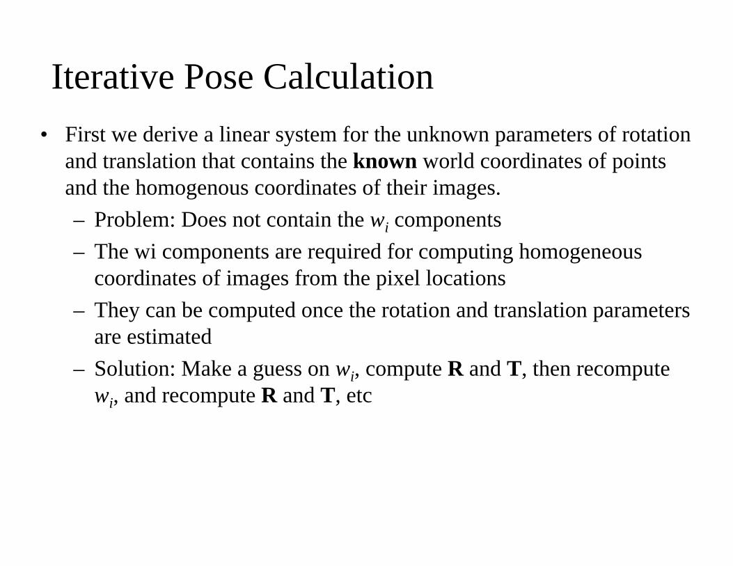
Iterative Pose Calculation• First we derive a linear system for the unknown parameters of rotation
and translation that contains the known world coordinates of points and the homogenous coordinates of their images.– Problem: Does not contain the wi components– The wi components are required for computing homogeneous
coordinates of images from the pixel locations– They can be computed once the rotation and translation parameters
are estimated– Solution: Make a guess on wi, compute R and T, then recompute
wi, and recompute R and T, etc
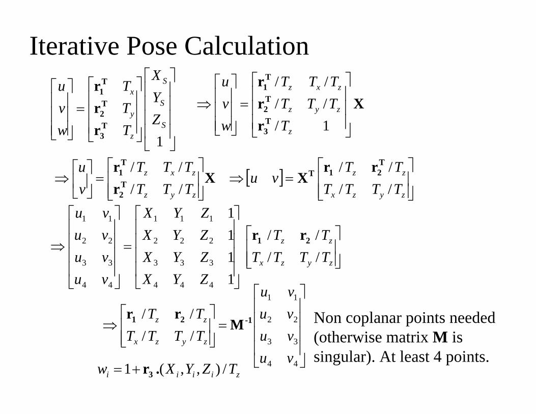
Iterative Pose Calculation
⎥⎥⎥⎥
⎦
⎤
⎢⎢⎢⎢
⎣
⎡
⎥⎥⎥
⎦
⎤
⎢⎢⎢
⎣
⎡
=⎥⎥⎥
⎦
⎤
⎢⎢⎢
⎣
⎡
1S
S
S
z
y
x
ZYX
TTT
wvu
T3
T2
T1
rrr
Xrrr
T3
T2
T1
⎥⎥⎥
⎦
⎤
⎢⎢⎢
⎣
⎡
=⎥⎥⎥
⎦
⎤
⎢⎢⎢
⎣
⎡⇒
1/////
z
zyz
zxz
TTTTTTT
wvu
ziiii TZYXw /),,(1 .r3+=
Xrr
T2
T1
⎥⎥⎦
⎤
⎢⎢⎣
⎡=⎥
⎦
⎤⎢⎣
⎡⇒
zyz
zxz
TTTTTT
vu
//// [ ]
⎥⎥⎦
⎤
⎢⎢⎣
⎡=⇒
zyzx
zz
TTTTTT
vu//// T
21T rrX
⎥⎥⎦
⎤
⎢⎢⎣
⎡
⎥⎥⎥⎥
⎦
⎤
⎢⎢⎢⎢
⎣
⎡
=
⎥⎥⎥⎥
⎦
⎤
⎢⎢⎢⎢
⎣
⎡
⇒zyzx
zz
TTTTTT
ZYXZYXZYXZYX
vuvuvuvu
////
1111
444
333
222
111
44
33
22
11
21 rr
⎥⎥⎥⎥
⎦
⎤
⎢⎢⎢⎢
⎣
⎡
=⎥⎥⎦
⎤
⎢⎢⎣
⎡⇒
44
33
22
11
////
vuvuvuvu
TTTTTT
zyzx
zz -121 Mrr Non coplanar points needed
(otherwise matrix M is singular). At least 4 points.
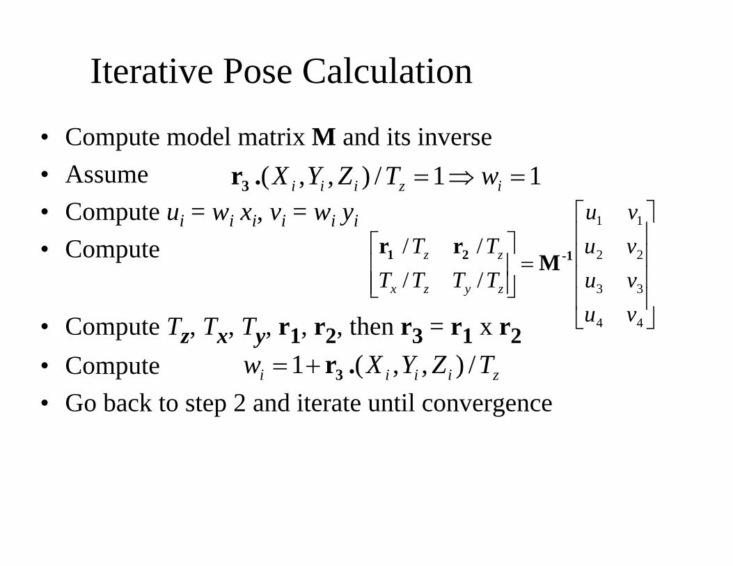
Iterative Pose Calculation
• Compute model matrix M and its inverse• Assume• Compute ui = wi xi, vi = wi yi
• Compute
• Compute Tz, Tx, Ty, r1, r2, then r3 = r1 x r2• Compute• Go back to step 2 and iterate until convergence
ziiii TZYXw /),,(1 .r3+=
⎥⎥⎥⎥
⎦
⎤
⎢⎢⎢⎢
⎣
⎡
=⎥⎥⎦
⎤
⎢⎢⎣
⎡
44
33
22
11
////
vuvuvuvu
TTTTTT
zyzx
zz -121 Mrr
11/),,( =⇒= iziii wTZYX.r3
Iterative Pose Calculation
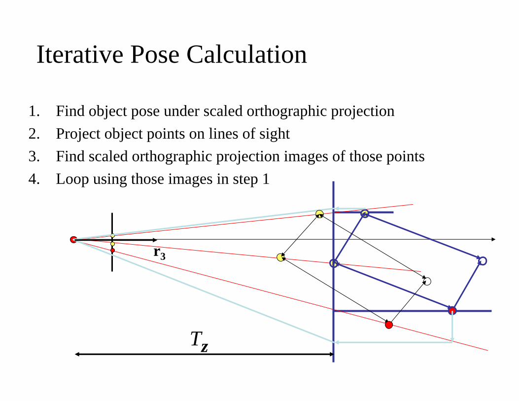
1. Find object pose under scaled orthographic projection2. Project object points on lines of sight3. Find scaled orthographic projection images of those points4. Loop using those images in step 1
r3
Tz
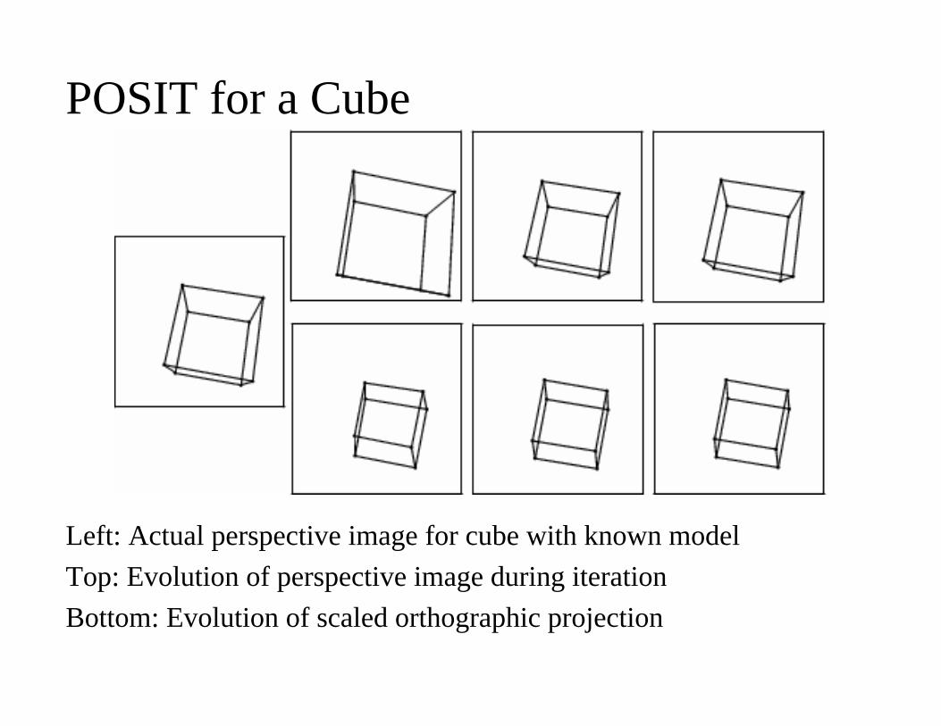
POSIT for a Cube
Left: Actual perspective image for cube with known modelTop: Evolution of perspective image during iterationBottom: Evolution of scaled orthographic projection
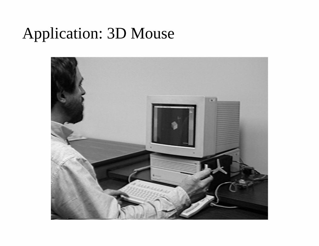
Application: 3D Mouse
3 Points
• Each correspondence between scene point and image point determines 2 equations
• Since there are 6 degrees of freedom in the pose problems, the correspondences between 3 scene points in a known configuration and 3 image points should provide enough equations for computing the pose of the 3 scene points
• the pose of a triangle of known dimension is defined from a single image of the triangle– But nonlinear method, 2 to 4 solutions
Triangle Pose Problem• There are two basic approaches
– Analytically solving for unknown pose parameters• Solving a 4th degree equation in one pose parameter, and then using
the 4 solutions to the equation to solve for remaining pose parameters• problem: errors in estimating location of image features can lead to
either large pose errors or failure to solve the 4th degree equation
– Approximate numerical algorithms • find solutions when exact methods fail due to image measurement error• more computation
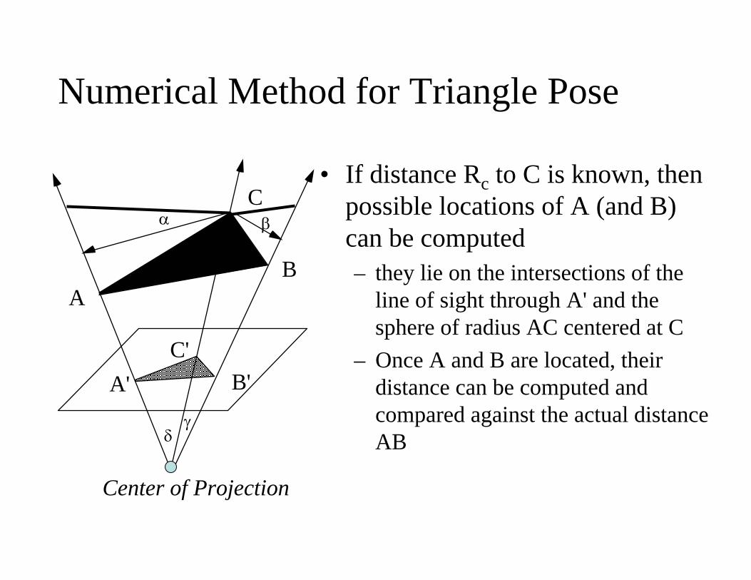
Numerical Method for Triangle Pose
α β
δ
A' B'C'
AB
C• If distance Rc to C is known, then
possible locations of A (and B) can be computed– they lie on the intersections of the
line of sight through A' and the sphere of radius AC centered at C
– Once A and B are located, their distance can be computed and compared against the actual distance AB
γ
Center of Projection
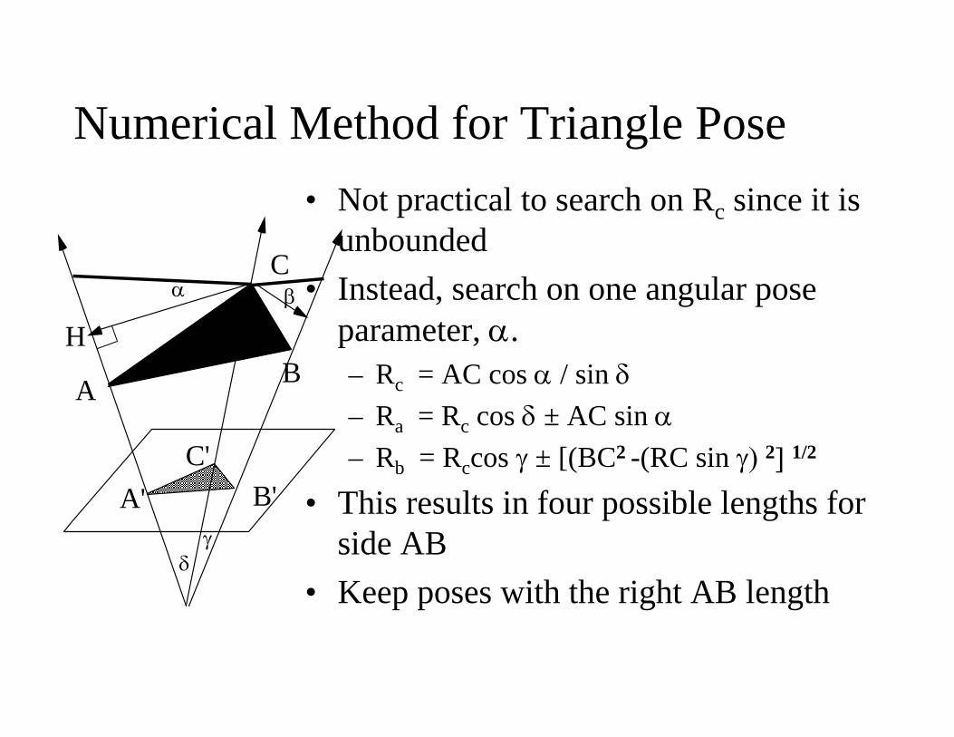
• Not practical to search on Rc since it is unbounded
• Instead, search on one angular pose parameter, α.– Rc = AC cos α / sin δ– Ra = Rc cos δ ± AC sin α– Rb = Rccos γ ± [(BC2 -(RC sin γ) 2] 1/2
• This results in four possible lengths for side AB
• Keep poses with the right AB length
Numerical Method for Triangle Pose
α β
δγ
A' B'C'
A B
C
H
Choosing Points on Objects
• Given a 3-D object, how do we decide which points from its surface to choose for its model?– Choose points that will give rise to detectable features in
images– For polyhedra, the images of its vertices will be points
in the images where two or more long lines meet• These can be detected by edge detection methods
– Points on the interiors of regions, or along straight lines are not easily identified in images.
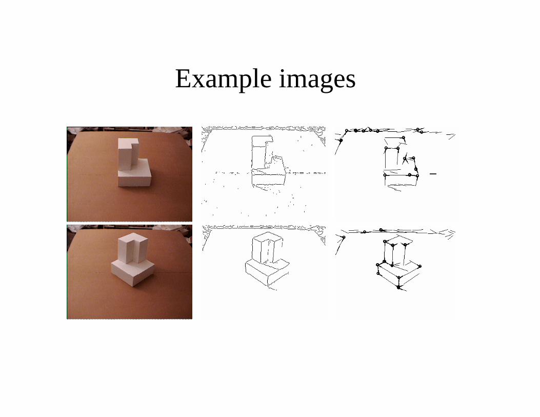
Example images
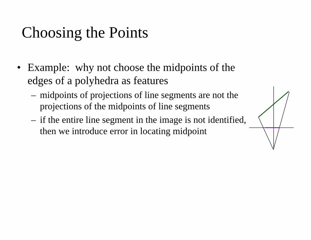
Choosing the Points
• Example: why not choose the midpoints of the edges of a polyhedra as features– midpoints of projections of line segments are not the
projections of the midpoints of line segments– if the entire line segment in the image is not identified,
then we introduce error in locating midpoint
Objects and Unknown Correspondences• Strategy:
– Pick up a small group of points (3 or 4) on object, and candidate image points in image
– Find object pose for these correspondences– Check or accumulate evidence by one of following techniques:
• Clustering in pose space• Image-Model Alignment and RANSAC
4-3-2-?• 4 - point perspective solution
– Unique solution for 6 pose parameters
• 3 - point perspective solution– Generally two solutions per triangle pair, but sometimes
four.
• 2 as we saw in the beginning of class many solutions
Reducing the Combinatorics of Pose Estimation• How can we reduce the number of matches
– Consider only quadruples of object features that are simultaneously visible
• extensive preprocessing
Reducing the Combinatorics of Pose Estimation
• Reducing the number of matches– Consider only quadruples of image features that
• Are connected by edges• Are “close” to one another
– But not too close or the inevitable errors in estimating the position of an image vertex will lead to large errors in pose estimation
– Generally, try to group the image features into sets that are probably from a single object, and then only construct quadruples from within a single group
Image-Model Alignment• Given:
– A 3-D object modeled as a collection of points– Image of a scene suspected to include an instance of the object, segmented
into feature points• Goal
– Hypothesize the pose of the object in the scene by matching (collections of)n model points against n feature points, enabling us to solve for the rigid body transformation from the object to world coordinate systems, and
– Verify that hypothesis by projecting the remainder of the model into the image and matching
• Look for edges connecting predicted vertex locations• Surface markings
RANSAC
• RANdom SAmple Consensus• Randomly select a set of 3 points in the image
and a select a set of 3 points in the model• Compute triangle pose and pose of model• Project model at computed pose onto image• Determine the set of projected model points that are within a
distance threshold t of image points, called the consensus set• After N trials, select pose with largest consensus set
Clustering in Pose Space• Each matching of n model points against n feature
points provides R and T• Each correct matching provides a similar rotation
and translation• Represent each pose by a point in a 6D space. Then
points from correct matchings should cluster• Or find clusters for points T and find the cluster
where the rotations are most consistent– “Generalized Hough transform” if bins are used
Pose and Recognition
• Solving the Pose Problem can be used to solve the Recognition Problem for 3D objects:– Try to find the pose of each item in the database of objects
we want to identify– Select the items whose projected points match the largest
amounts of image points in the verification stage, and label the corresponding image regions with the item names.
– But many alternative recognition techniques do not provide the pose of the recognized item.
Pose: Ransac• Match enough features in model to features in image to
determine pose. • Examples:
– match a point and determine translation.– match a corner and determine translation and rotation.– Points and translation, rotation, scaling?– Lines and rotation and translation?
Transforming the Object
1 21 2 3 4
1 21 2 3 4
1 21 1 1 1
. . .? ? ? ?? ? ?? ? ? ?? ? ?? ? ? ?? ? ?
1 1 1
n
n
n
x x xu u u u
y y yv v v v
z z zw w w w
⎛ ⎞⎛ ⎞ ⎛ ⎞ ⎜ ⎟⎜ ⎟ ⎜ ⎟ ⎜ ⎟=⎜ ⎟ ⎜ ⎟⎜ ⎟⎜ ⎟⎜ ⎟ ⎜ ⎟⎝ ⎠⎝ ⎠
⎝ ⎠
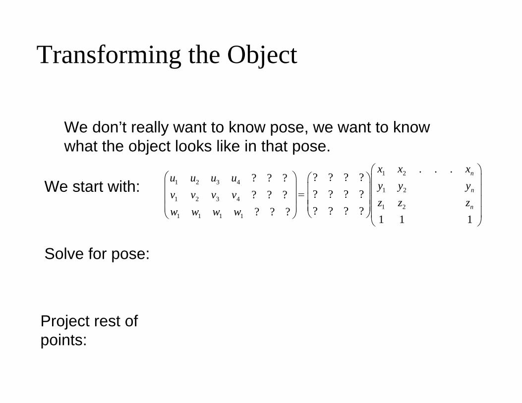
We don’t really want to know pose, we want to know what the object looks like in that pose.
We start with:
Solve for pose:
Project rest of points:
Transforming object with Linear Combinations
⎠
⎞
⎜⎜⎜⎜⎜
⎝
⎛
22
2
2
1
22
2
2
1
11
2
1
1
11
2
1
1...
n
n
n
n
vvvuuuvvvuuu
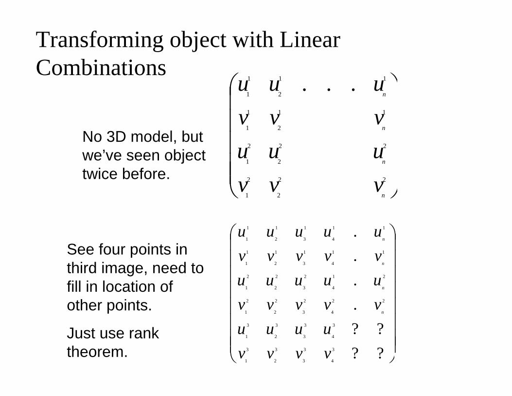
No 3D model, but we’ve seen object twice before.
⎟⎟⎟⎟⎟⎟⎟⎟
⎠
⎞
⎜⎜⎜⎜⎜⎜⎜⎜
⎝
⎛
????
.
.
.
.
3
4
3
3
3
2
3
1
3
4
3
3
3
2
3
1
22
4
2
3
2
2
2
1
21
4
2
3
2
2
2
1
11
4
1
3
1
2
1
1
11
4
1
3
1
2
1
1
vvvvuuuu
vvvvvuuuuuvvvvvuuuuu
n
n
n
n
See four points in third image, need to fill in location of other points.
Just use rank theorem.
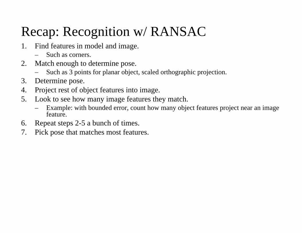
Recap: Recognition w/ RANSAC1. Find features in model and image.
– Such as corners.2. Match enough to determine pose.
– Such as 3 points for planar object, scaled orthographic projection.3. Determine pose.4. Project rest of object features into image.5. Look to see how many image features they match.
– Example: with bounded error, count how many object features project near an image feature.
6. Repeat steps 2-5 a bunch of times.7. Pick pose that matches most features.
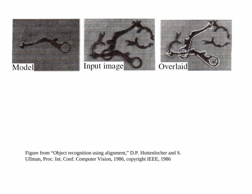
Figure from “Object recognition using alignment,” D.P. Huttenlocher and S. Ullman, Proc. Int. Conf. Computer Vision, 1986, copyright IEEE, 1986
Recognizing 3D Objects• Previous approach will work.• But slow. RANSAC considers n3m3 possible matches.
About m3 correct. • Solutions:
– Grouping. Find features coming from single object.– Viewpoint invariance. Match to small set of model features that
could produce them.