Lecture 2: Software Platforms Anish Arora CIS788.11J Introduction to Wireless Sensor Networks...
121
Lecture 2: Software Platforms Anish Arora CIS788.11J Introduction to Wireless Sensor Networks Lecture uses slides from tutorials prepared by authors of these
-
Upload
jennifer-glenn -
Category
Documents
-
view
225 -
download
3
Transcript of Lecture 2: Software Platforms Anish Arora CIS788.11J Introduction to Wireless Sensor Networks...

Lecture 2: Software Platforms
Anish Arora
CIS788.11J
Introduction to Wireless Sensor Networks
Lecture uses slides from tutorials prepared by authors of these platforms

2
Outline
• Discussion includes OS and also prog. methodology some environments focus more on one than the other
• Focus is on node centric platforms
(vs. distributed system centric platforms) composability, energy efficiency, robustness reconfigurability and pros/cons of interpreted approach
• Platforms TinyOS (applies to XSMs) slides from UCB EmStar (applies to XSSs) slides from UCLA SOS slides from UCLA Contiki slides from Upsaala Virtual machines (Maté) slides from UCB
3
• NesC, Programming Manual, The Emergence of Networking Abstractions and Techniques in TinyOS, TinyOS webpage
• EmStar: An Environment for Developing Wireless Embedded Systems Software, Sensys04 Paper, EmStar webpage
• SOS Mobisys paper, SOS webpage
• Contiki Emnets Paper, Sensys06 Paper, Contiki webpage
• Mate ASPLOS Paper, Mate webpage, (SUNSPOT)
References

4
Traditional Systems
• Well established layers of abstractions
• Strict boundaries• Ample resources• Independent
applications at endpoints communicate pt-pt through routers
• Well attended
User
System
Physical Layer
Data Link
Network
Transport
Network Stack
Threads
Address Space
Drivers
Files
Application
Application
Routers

5
Sensor Network Systems
• Highly constrained resources
processing, storage, bandwidth, power, limited hardware parallelism,
relatively simple interconnect
• Applications spread over many small nodes self-organizing collectives
highly integrated with changing environment and network
diversity in design and usage
• Concurrency intensive in bursts
streams of sensor data & network traffic
• Robust
inaccessible, critical operation
• Unclear where the boundaries belong
Need a framework for:
• Resource-constrained concurrency
• Defining boundaries
• Appl’n-specific processing
allow abstractions to emerge

6
Choice of Programming Primitives
• Traditional approaches
command processing loop (wait request, act, respond)
monolithic event processing
full thread/socket posix regime
• Alternative provide framework for concurrency and modularity
never poll, never block
interleaving flows, events

7
TinyOS
• Microthreaded OS (lightweight thread support) and
efficient network interfaces
• Two level scheduling structure
Long running tasks that can be interrupted by hardware
events
• Small, tightly integrated design that allows crossover of
software components into hardware

8
Tiny OS Concepts
• Scheduler + Graph of Components constrained two-level scheduling
model: threads + events
• Component: Commands Event Handlers Frame (storage) Tasks (concurrency)
• Constrained Storage Model frame per component, shared stack, no
heap
• Very lean multithreading
• Efficient Layering
Messaging Component
init
Po
we
r(m
od
e)
TX
_p
ack
et(
bu
f)
TX
_p
ack
et_
do
ne
(s
ucc
ess
)
RX
_p
ack
et_
do
ne
(b
uff
er)
Internal
State
init
po
we
r(m
od
e)
sen
d_
msg
(ad
dr,
ty
pe
, d
ata
)
msg
_re
c(ty
pe
, d
ata
)
msg
_se
nd
_d
on
e)
internal thread
Commands Events

9
Application = Graph of Components
RFM
Radio byte
Radio Packet
UART
Serial Packet
ADC
Temp Photo
Active Messages
clock
bit
by
tep
ac
ke
t
Route map Router Sensor Appln
ap
pli
ca
tio
n
HW
SW
Example: ad hoc, multi-hop routing of photo sensor readings
3450 B code 226 B data
Graph of cooperatingstate machines on shared stack
10
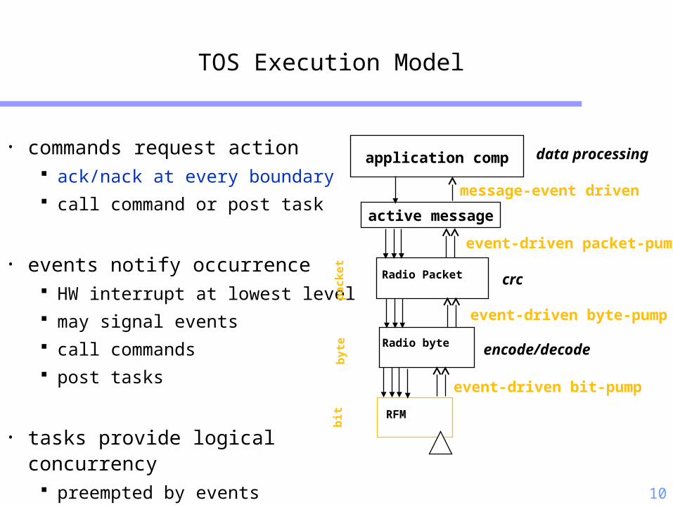
TOS Execution Model
• commands request action ack/nack at every boundary call command or post task
• events notify occurrence HW interrupt at lowest level may signal events call commands post tasks
• tasks provide logical concurrency preempted by events
RFM
Radio byte
Radio Packet
bit
by
tep
ac
ke
t
event-driven bit-pump
event-driven byte-pump
event-driven packet-pump
message-event driven
active message
application comp
encode/decode
crc
data processing

11
Event-Driven Sensor Access Pattern
• clock event handler initiates data collection• sensor signals data ready event• data event handler calls output command• device sleeps or handles other activity while waiting• conservative send/ack at component boundary
command result_t StdControl.start() {
return call Timer.start(TIMER_REPEAT, 200);
}
event result_t Timer.fired() {
return call sensor.getData();
}
event result_t sensor.dataReady(uint16_t data) {
display(data)
return SUCCESS;
}
SENSE
Timer Photo LED

12
TinyOS Commands and Events
{... status = call CmdName(args)...}
command CmdName(args) {...return status;}
{... status = signal EvtName(args) ...}
event EvtName(args) {...return status;}

13
TinyOS Execution Contexts
• Events generated by interrupts preempt tasks
• Tasks do not preempt tasks
• Both essentially process state transitions
Hardware
Interrupts
eve
nts
commands
Tasks
14
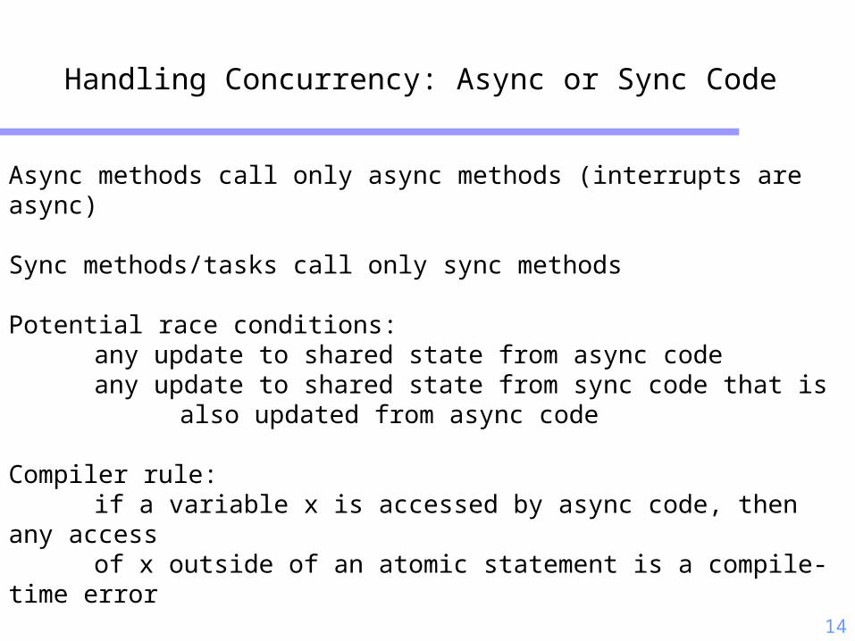
Handling Concurrency: Async or Sync Code
Async methods call only async methods (interrupts are async)
Sync methods/tasks call only sync methods
Potential race conditions:any update to shared state from async codeany update to shared state from sync code that is
also updated from async code
Compiler rule:if a variable x is accessed by async code, then any accessof x outside of an atomic statement is a compile-time error
Race-Free Invariant: any update to shared state is either not a potential racecondition (sync code only) or is within an atomic section

15
Tasks
• provide concurrency internal to a component longer running operations
• are preempted by events
• not preempted by tasks
• able to perform operations beyond event context
• may call commands
• may signal events
{...post TskName();...}
task void TskName {...}

16
Typical Application Use of Tasks
• event driven data acquisition• schedule task to do computational portion
event result_t sensor.dataReady(uint16_t data) {
putdata(data);
post processData();
return SUCCESS;
}
task void processData() {
int16_t i, sum=0;
for (i=0; i ‹ maxdata; i++)
sum += (rdata[i] ›› 7);
display(sum ›› shiftdata);
}
• 128 Hz sampling rate• simple FIR filter• dynamic software tuning for centering the magnetometer signal (1208 bytes)
• digital control of analog, not DSP• ADC (196 bytes)

17
Task Scheduling
• Typically simple FIFO scheduler
• Bound on number of pending tasks
• When idle, shuts down node except clock
• Uses non-blocking task queue data structure
• Simple event-driven structure + control over complete
application/system graph
instead of complex task priorities and IPC

18
Maintaining Scheduling Agility
• Need logical concurrency at many levels of the graph
• While meeting hard timing constraints
sample the radio in every bit window
Retain event-driven structure throughout application
Tasks extend processing outside event window
All operations are non-blocking

19
RadioTimingSecDedEncode
The Complete Application
RadioCRCPacket
UART
UARTnoCRCPacket
ADC
phototemp
AMStandard
ClockC
bit
by
tep
ac
ke
t
SenseToRfm
HW
SW
IntToRfm
MicaHighSpeedRadioM
RandomLFSRSPIByteFIFO
SlavePin
noCRCPacket
Timer photo
ChannelMon
generic comm
CRCfilter

20
Programming Syntax
• TinyOS 2.0 is written in an extension of C, called nesC
• Applications are too just additional components composed with OS components
• Provides syntax for TinyOS concurrency and storage model commands, events, tasks local frame variable
• Compositional support separation of definition and linkage
robustness through narrow interfaces and reuse
interpositioning
• Whole system analysis and optimization

21
Component Interface
• logically related set of commands and events
StdControl.nc
interface StdControl {
command result_t init();
command result_t start();
command result_t stop();
}
Clock.nc
interface Clock {
command result_t setRate(char interval, char scale);
event result_t fire();
}

22
Component Types
• Configuration
links together components to compose new component
configurations can be nested
complete “main” application is always a configuration
• Module
provides code that implements one or more interfaces and
internal behavior

23
Example of Top Level Configuration
configuration SenseToRfm {
// this module does not provide any interface
}
implementation
{
components Main, SenseToInt, IntToRfm, ClockC, Photo as Sensor;
Main.StdControl -> SenseToInt;
Main.StdControl -> IntToRfm;
SenseToInt.Clock -> ClockC;
SenseToInt.ADC -> Sensor;
SenseToInt.ADCControl -> Sensor;
SenseToInt.IntOutput -> IntToRfm;
}
SenseToInt
ClockC Photo
Main
StdControl
ADCControl IntOutputClock ADC
IntToRfm

24
Nested Configuration
includes IntMsg;
configuration IntToRfm{
provides {
interface IntOutput;
interface StdControl;
}
}
implementation
{
components IntToRfmM, GenericComm as Comm;
IntOutput = IntToRfmM;
StdControl = IntToRfmM;
IntToRfmM.Send -> Comm.SendMsg[AM_INTMSG];
IntToRfmM.SubControl -> Comm;
}
IntToRfmM
GenericComm
StdControl IntOutput
SubControl SendMsg[AM_INTMSG];

25
IntToRfm Module
includes IntMsg;
module IntToRfmM
{
uses {
interface StdControl as SubControl;
interface SendMsg as Send;
}
provides {
interface IntOutput;
interface StdControl;
}
}
implementation
{
bool pending;
struct TOS_Msg data;
command result_t StdControl.init() {
pending = FALSE;
return call SubControl.init();
}
command result_t StdControl.start()
{ return call SubControl.start(); }
command result_t StdControl.stop()
{ return call SubControl.stop(); }
command result_t IntOutput.output(uint16_t value)
{
...
if (call Send.send(TOS_BCAST_ADDR,sizeof(IntMsg), &data)
return SUCCESS;
...
}
event result_t Send.sendDone(TOS_MsgPtr msg, result_t success)
{
...
}
}

26
Atomicity Support in nesC
• Split phase operations require care to deal with pending operations
• Race conditions may occur when shared state is accessed by premptible executions, e.g. when an event accesses a shared state, or when a task updates state (premptible by an event which then uses that state)
• nesC supports atomic block implemented by turning of interrupts for efficiency, no calls are allowed in block access to shared variable outside atomic block is not allowed
27
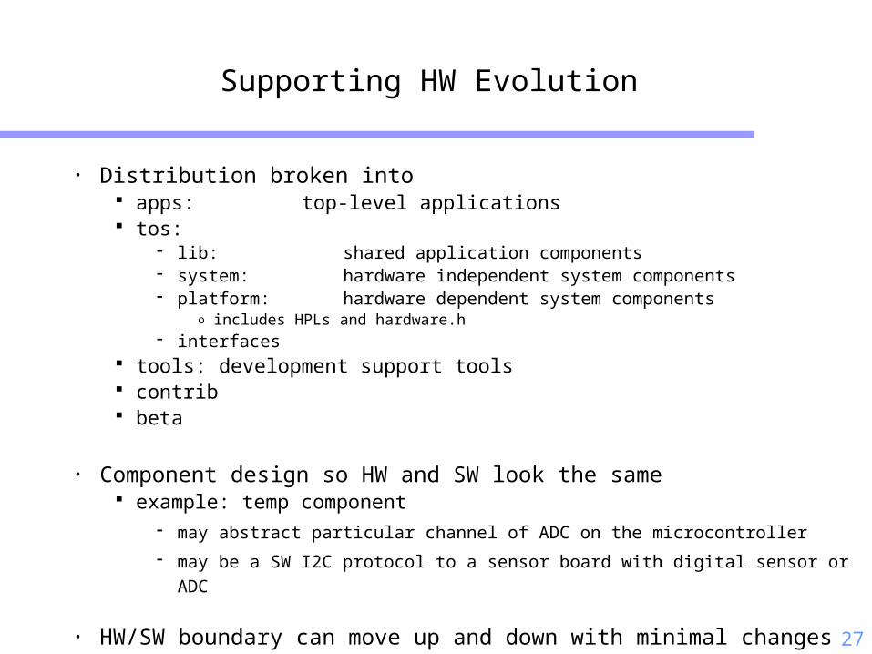
Supporting HW Evolution
• Distribution broken into apps: top-level applications tos:
lib: shared application components system: hardware independent system components platform: hardware dependent system components
o includes HPLs and hardware.h interfaces
tools: development support tools contrib beta
• Component design so HW and SW look the same example: temp component
may abstract particular channel of ADC on the microcontroller
may be a SW I2C protocol to a sensor board with digital sensor or ADC
• HW/SW boundary can move up and down with minimal changes
28
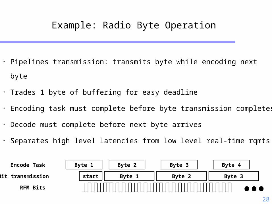
Example: Radio Byte Operation
• Pipelines transmission: transmits byte while encoding next byte
• Trades 1 byte of buffering for easy deadline
• Encoding task must complete before byte transmission completes
• Decode must complete before next byte arrives
• Separates high level latencies from low level real-time rqmts
Encode Task
Bit transmission Byte 1
Byte 2
RFM Bits
Byte 2
Byte 1 Byte 3
Byte 3
Byte 4
start …

29
Dynamics of Events and Threads
bit event filtered at byte layer
bit event => end of byte =>
end of packet => end of msg send
thread posted to start
send next message
radio takes clock events to detect recv

30
Sending a Message
bool pending;
struct TOS_Msg data;
command result_t IntOutput.output(uint16_t value) {
IntMsg *message = (IntMsg *)data.data;
if (!pending) {
pending = TRUE;
message->val = value;
message->src = TOS_LOCAL_ADDRESS;if (call Send.send(TOS_BCAST_ADDR, sizeof(IntMsg), &data))
return SUCCESS;
pending = FALSE;
}
return FAIL;
}destination length
• Refuses to accept command if buffer is still full or network refuses to accept send command
• User component provide structured msg storage

31
Send done Event
• Send done event fans out to all potential senders
• Originator determined by match
free buffer on success, retry or fail on failure
• Others use the event to schedule pending communication
event result_t IntOutput.sendDone(TOS_MsgPtr msg, result_t success)
{
if (pending && msg == &data) {
pending = FALSE;
signal IntOutput.outputComplete(success);
}
return SUCCESS;
}
}

32
Receive Event
• Active message automatically dispatched to associated handler knows format, no run-time parsing
performs action on message event
• Must return free buffer to the system typically the incoming buffer if processing complete
event TOS_MsgPtr ReceiveIntMsg.receive(TOS_MsgPtr m) {
IntMsg *message = (IntMsg *)m->data;
call IntOutput.output(message->val);
return m;
}

33
Tiny Active Messages
• Sending declare buffer storage in a frame request transmission name a handler handle completion signal
• Receiving declare a handler firing a handler: automatic
• Buffer management strict ownership exchange tx: send done event reuse rx: must return a buffer

34
Tasks in Low-level Operation
• transmit packet send command schedules task to calculate CRC task initiates byte-level data pump events keep the pump flowing
• receive packet receive event schedules task to check CRC task signals packet ready if OK
• byte-level tx/rx task scheduled to encode/decode each complete byte
must take less time that byte data transfer

35
TinyOS tools
• TOSSIM: a simulator for tinyos programs
• ListenRaw, SerialForwarder: java tools to receive raw packets on PC from base node
• Oscilloscope: java tool to visualize (sensor) data in real time
• Memory usage: breaks down memory usage per component (in contrib)
• Peacekeeper: detect RAM corruption due to stack overflows (in lib)
• Stopwatch: tool to measure execution time of code block by timestamping at entry and exit (in osu CVS server)
• Makedoc and graphviz: generate and visualize component hierarchy
• Surge, Deluge, SNMS, TinyDB

36
Scalable Simulation Environment
• target platform: TOSSIM whole application compiled for host native instruction set event-driven execution mapped into event-driven simulator
machinery storage model mapped to thousands of virtual nodes
• radio model and environmental model plugged in
bit-level fidelity
• Sockets = basestation
• Complete application including GUI

37
Simulation Scaling

38
TinyOS 2.0: basic changes
• Scheduler: improve robustness and flexibility Reserved tasks by default ( fault tolerance) Priority tasks
• New nesC 1.2 features: Network types enable link level cross-platform interoperability Generic (instantiable) components, attributes, etc.
• Platform definition: simplify porting Structure OS to leverage code reuse Decompose h/w devices into 3 layers: presentation, abstraction, device-independent Structure common chips for reuse across platforms
so platforms are a collection of chips: msp430 + CC2420 +
• Power mgmt architecture for devices controlled by resource reservation • Self-initialisation
• App-level notion of instantiable services

44
TinyOS Limitations
• Static allocation allows for compile-time analysis, but can make programming harder
• No support for heterogeneity Support for other platforms (e.g. stargate)
Support for high data rate apps (e.g. acoustic beamforming)
Interoperability with other software frameworks and languages
• Limited visibility
Debugging
Intra-node fault tolerance
• Robustness solved in the details of implementation nesC offers only some types of checking
45
Em*
• Software environment for sensor networks built from Linux-class devices
• Claimed features:
Simulation and emulation tools
Modular, but not strictly layered architecture
Robust, autonomous, remote operation
Fault tolerance within node and between nodes
Reactivity to dynamics in environment and task
High visibility into system: interactive access to all services

46
Contrasting Emstar and TinyOS
• Similar design choices programming framework
Component-based design “Wiring together” modules into an application
event-driven reactive to “sudden” sensor events or triggers
robustness Nodes/system components can fail
• Differences
hardware platform-dependent constraints Emstar: Develop without optimization TinyOS: Develop under severe resource-constraints
operating system and language choices Emstar: easy to use C language, tightly coupled to linux (devfs,redhat,…) TinyOS: an extended C-compiler (nesC), not wedded to any OS

47
Em* Transparently Trades-off Scale vs. Reality
Em* code runs transparently at many degrees of “reality”: high
visibility debugging before low-visibility deployment
Reality
Scale
Pure Simulation
Data Replay
Portable Array
Deployment
Ceiling Array

48
Em* Modularity
• Dependency DAG
• Each module (service) Manages a resource & resolves
contention
Has a well defined interface
Has a well scoped task
Encapsulates mechanism
Exposes control of policy
Minimizes work done by client library
• Application has same structure as “services”
Hardware Radio
Topology Discovery
Collaborative SensorProcessing Application
NeighborDiscovery
ReliableUnicast
Sensors
LeaderElection
3d Multi-Lateration
Audio
TimeSync
AcousticRanging
StateSync

49
Em* Robustness
• Fault isolation via multiple processes
• Active process management (EmRun)
• Auto-reconnect built into libraries
“Crashproofing” prevents cascading failure
• Soft state design style
Services periodically refresh clients
Avoid “diff protocols”
motor_x motor_y
scheduling
path_plandepth map
camera
EmRun

50
Em* Reactivity
• Event-driven software structure
React to asynchronous notification
e.g. reaction to change in neighbor list
• Notification through the layers
Events percolate up
Domain-specific filtering at every level
e.g.
neighbor list membership hysteresis
time synchronization linear fit and outlier rejection
motor_y
scheduling
path_plan
notifyfilter

51
• Tools EmRun
EmProxy/EmView
EmTOS
• Standard IPC FUSD
Device patterns
• Common Services NeighborDiscovery
TimeSync
Routing
EmStar Components

52
EmRun: Manages Services
• Designed to start, stop, and monitor services
• EmRun config file specifies service dependencies
• Starting and stopping the system Starts up services in correct order Can detect and restart unresponsive services Respawns services that die Notifies services before shutdown, enabling graceful
shutdown and persistent state
• Error/Debug Logging Per-process logging to in-memory ring buffers Configurable log levels, at run time

53
EmSim/EmCee
• Em* supports a variety of types of simulation and emulation, from simulated radio channel and sensors to emulated radio and sensor channels (ceiling array)
• In all cases, the code is identical
• Multiple emulated nodes run in their own spaces, on the same physical machine

54
EmView/EmProxy: Visualization
emviewEmulator
nodeNnodeNnodeN
Mote Mote … Mote
motenic
linkstat
neighbor
emproxy
…

55
Inter-module IPC : FUSD
• Creates device file interfaces
• Text/Binary on same file
• Standard interface Language independent No client library required
Client Server
kfusd.o
/dev/fusd/dev/servicename
Kernel
User

56
Device Patterns
• FUSD can support virtually any semantics What happens when client calls read()?
• But many interfaces fall into certain patterns
• Device Patterns
encapsulate specific semantics
take the form of a library:
objects, with method calls and callback functions
priority: ease of use

57
Status Device
• Designed to report current state no queuing: clients not guaranteed to see
every intermediate state
• Supports multiple clients
• Interactive and programmatic interface ASCII output via “cat” binary output to programs
• Supports client notification notification via select()
• Client configurable client can write command string server parses it to enable per-client
behavior
Status Device
Server
O I
Client1 Client2 Client3
ConfigHandler
State RequestHandler

58
Packet Device
• Designed for message streams
• Supports multiple clients
• Supports queuing Round-robin service of output
queues Delivery of messages to all/
specific clients
• Client-configurable: Input and output queue lengths Input filters Optional loopback of outputs to
other clients (for snooping)
Packet Device
Server
Client1
I O
F
Client2
I O
F
Client3
I O
F
O I

59
Device Files vs Regular Files
• Regular files: Require locking semantics to prevent race conditions between readers
and writers
Support “status” semantics but not queuing
No support for notification, polling only
• Device files: Leverage kernel for serialization: no locking needed
Arbitrary control of semantics: queuing, text/binary, per client configuration
Immediate action, like an function call: system call on device triggers immediate response from service, rather than
setting a request and waiting for service to poll

60
Interacting With em*
• Text/Binary on same device file Text mode enables interaction from
shell and scripts Binary mode enables easy
programmatic access to data as C structures, etc.
• EmStar device patterns support multiple concurrent clients IPC channels used internally can be
viewed concurrently for debugging “Live” state can be viewed in the shell
(“echocat –w”) or using emview
61
SOS: Motivation and Key Feature
• Post-deployment software updates are necessary to
• customize the system to the environment• upgrade features• remove bugs• re-task system
• Remote reprogramming is desirable
• Approach: Remotely insert binary modules into running kernel
software reconfiguration without interrupting system operation
no stop and re-boot unlike differential patching
• Performance should be superior to virtual machines
62
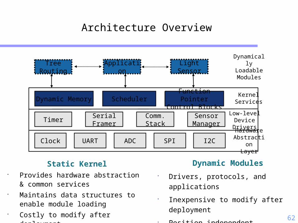
Architecture Overview
Clock
Timer
I2CADC SPIUART
SensorManager
Comm.Stack
SerialFramer
Dynamic Memory SchedulerFunction PointerControl Blocks
HardwareAbstraction
Layer
KernelServices
Low-levelDeviceDrivers
TreeRouting
LightSensor
ApplicationDynamically
LoadableModules
LightSensor
Static Kernel• Provides hardware abstraction &
common services• Maintains data structures to enable
module loading• Costly to modify after deployment
Dynamic Modules• Drivers, protocols, and applications
• Inexpensive to modify after deployment
• Position independent

63
SOS Kernel
• Hardware Abstraction Layer (HAL)• Clock, UART, ADC, SPI, etc.
• Low layer device drivers interface with HAL• Timer, serial framer, communications stack, etc.
• Kernel services• Dynamic memory management• Scheduling• Function control blocks

64
Kernel Services: Memory Management
• Fixed-partition dynamic memory allocation• Constant allocation time
• Low overhead
• Memory management features• Guard bytes for run-time memory overflow checks
• Ownership tracking
• Garbage collection on completion
• pkt = (uint8_t*)ker_malloc(hdr_size + sizeof(SurgeMsg), SURGE_MOD_PID);

65
Kernel Services: Scheduling
• SOS implements non-preemptive priority scheduling via priority queues
• Event served when there is no higher priority event • Low priority queue for scheduling most events
• High priority queue for time critical events, e.g., h/w interrupts &
sensitive timers
• Prevents execution in interrupt contexts
• post_long(TREE_ROUTING_PID, SURGE_MOD_PID, MSG_SEND_PACKET,
hdr_size + sizeof(SurgeMsg), (void*)packet, SOS_MSG_DYM_MANAGED);

66
Modules
• Each module is uniquely identified by its ID or pid
• Has private state
• Represented by a message handler & has prototype:
int8_t handler(void *private_state, Message *msg)
• Return value follows errno
SOS_OK for success. -EINVAL, -ENOMEM, etc. for failure

67
Kernel Services: Module Linking
• Orthogonal to module distribution protocol
• Kernel stores new module in free block located in program memory
and critical information about module in the module table
• Kernel calls initialization routine for module
• Publish functions for other parts of the system to usechar tmp_string = {'C', 'v', 'v', 0};
ker_register_fn(TREE_ROUTING_PID, MOD_GET_HDR_SIZE, tmp_string, (fn_ptr_t)tr_get_header_size);
• Subscribe to functions supplied by other moduleschar tmp_string = {'C', 'v', 'v', 0};
s->get_hdr_size = (func_u8_t*)ker_get_handle(TREE_ROUTING_PID, MOD_GET_HDR_SIZE, tmp_string);
• Set initial timers and schedule events
68
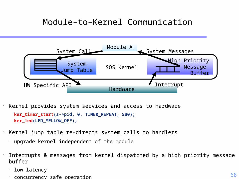
• Kernel provides system services and access to hardware
ker_timer_start(s->pid, 0, TIMER_REPEAT, 500);ker_led(LED_YELLOW_OFF);
• Kernel jump table re-directs system calls to handlers• upgrade kernel independent of the module
• Interrupts & messages from kernel dispatched by a high priority message buffer• low latency• concurrency safe operation
Module–to–Kernel Communication
Module A
SystemJump Table
Hardware
System Call
High PriorityMessage
Buffer
HW Specific API Interrupt
System Messages
SOS Kernel

69
Inter-Module Communication
Module A
Module FunctionPointer Table
Indirect Function Call
Module B
Inter-Module Message Passing
• Asynchronous communication
• Messages dispatched by a two-level priority scheduler
• Suited for services with long latency
• Type safe binding through publish / subscribe interface
Post
MessageBuffer
Module A Module B
Inter-Module Function Calls
• Synchronous communication
• Kernel stores pointers to functions registered by modules
• Blocking calls with low latency
• Type-safe runtime function binding

70
Synchronous Communication
• Module can register function for low latency blocking call (1)
• Modules which need such function can subscribe to it by getting function pointer pointer (i.e. **func) (2)
• When service is needed, module dereferences the function pointer pointer (3)
Module FunctionPointer Table
Module A Module B
3
12

71
Asynchronous Communication
• Module is active when it is handling the message (2)(4)
• Message handling runs to completion and can only be
interrupted by hardware interrupts
• Module can send message to another module (3) or send
message to the network (5)
• Message can come from both network (1) and local host (3)
Module A
Module BMsg Queue
2
3
Send Queue4 5
Network1
72
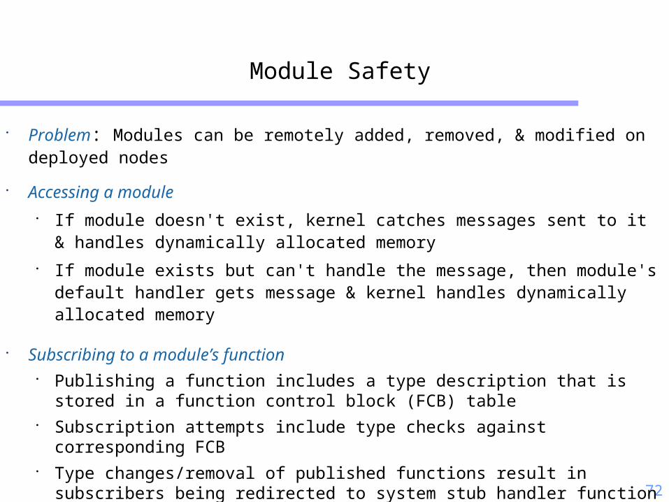
Module Safety
• Problem: Modules can be remotely added, removed, & modified on deployed nodes
• Accessing a module• If module doesn't exist, kernel catches messages sent to it & handles
dynamically allocated memory• If module exists but can't handle the message, then module's default
handler gets message & kernel handles dynamically allocated memory
• Subscribing to a module’s function• Publishing a function includes a type description that is stored in a
function control block (FCB) table• Subscription attempts include type checks against corresponding FCB• Type changes/removal of published functions result in subscribers being
redirected to system stub handler function specific to that type• Updates to functions w/ same type assumed to have same semantics

73
Module Library
SurgeMemoryDebug
PhotoSensor
TreeRouting
Surge Applicationwith Debugging
• Some applications created by combining already written and tested modules
• SOS kernel facilitates loosely coupled modules• Passing of memory ownership• Efficient function and messaging interfaces

74
Module Design
• Uses standard C
• Programs created by “wiring”
modules together
#include <module.h>
typedef struct { uint8_t pid; uint8_t led_on;} app_state;
DECL_MOD_STATE(app_state);DECL_MOD_ID(BLINK_ID);
int8_t module(void *state, Message *msg){ app_state *s = (app_state*)state; switch (msg->type){ case MSG_INIT: { s->pid = msg->did; s->led_on = 0; ker_timer_start(s->pid, 0, TIMER_REPEAT, 500); break; } case MSG_FINAL: { ker_timer_stop(s->pid, 0); break; } case MSG_TIMER_TIMEOUT: { if(s->led_on == 1){ ker_led(LED_YELLOW_ON); } else { ker_led(LED_YELLOW_OFF); } s->led_on++; if(s->led_on > 1) s->led_on = 0; break; } default: return -EINVAL; } return SOS_OK;}

75
Sensor Manager
• Enables sharing of sensor data between multiple modules
• Presents uniform data access API to diverse sensors
• Underlying device specific drivers register with the sensor manager
• Device specific sensor drivers control• Calibration• Data interpolation
• Sensor drivers are loadable: enables• post-deployment configuration of sensors• hot-swapping of sensors on a running node
PeriodicAccess
getData
Sensor Manager
Module A Module B
I2C
MagSensor
ADC
dataReady
SignalData Ready
PolledAccess

76
Application Level Performance
Comparison of application performance in SOS, TinyOS, and MateVM
Platform ROM RAMSOS Core 20464 B 1163 BDynamic Memory Pool - 1536 BTinyOS with Deluge 21132 B 597 BMate VM 39746 B 3196 B
Memory footprint for base operating system with the ability to distribute and update node programs.
SystemTinyOs 3.31 sec 5.22% NASOS 3.50 sec 5.84% 5.70%Mate VM 3.68 sec 6.13% 11.00%
Active Time(in 1 min)
Active Time (%)
Overhead relative to TOS (%)
CPU active time for surge application.
Surge Tree Formation Latency Surge Forwarding Delay Surge Packet Delivery Ratio

77
Reconfiguration Performance
• Energy trade offs SOS has slightly higher base operating cost TinyOS has significantly higher update cost SOS is more energy efficient when the system is updated
one or more times a week
Module Name Code Size (Bytes)sample_send 568tree_routing 2242photo_sensor 372Energy (mJ ) 2312.68Latency (sec) 46.6
SystemSOS 1316 0.31 1.86TinyOS 30988 1.34 164.02Mate VM NA NA NA
Code Size (Bytes)
Write Cost (mJ/page)
Write Energy (mJ)
SystemSOS 566 0.31 0.93TinyOS 31006 1.34 164.02Mate VM 17 0 0
Code Size (Bytes)
Write Cost (mJ/page)
Write Energy (mJ)
Energy cost of light sensor driver update
Energy cost of surge application update
Module size and energy profile for installing surge under SOS

78
Platform Support
Supported micro controllers
• Atmel Atmega128• 4 Kb RAM• 128 Kb FLASH
• Oki ARM• 32 Kb RAM• 256 Kb FLASH
Supported radio stacks
• Chipcon CC1000• BMAC
• Chipcon CC2420• IEEE 802.15.4 MAC
(NDA required)

79
Simulation Support
• Source code level network simulation• Pthread simulates hardware concurrency• UDP simulates perfect radio channel• Supports user defined topology & heterogeneous software configuration • Useful for verifying the functional correctness
• Instruction level simulation with Avrora• Instruction cycle accurate simulation• Simple perfect radio channel• Useful for verifying timing information• See http://compilers.cs.ucla.edu/avrora/
• EmStar integration under development

81
Contiki
Dynamic loading of programs (vs. static)
Multi-threaded concurrency managed execution (in addition to event driven)
Available on MSP430, AVR, HC12, Z80, 6502, x86, ...
Simulation environment available for BSD/Linux/Windows

82
Key ideas
• Dynamic loading of programs
Selective reprogramming
Static/pre-linking (early work: EmNets)
Dynamic linking (recent work: SENSYS)
Key difference from SOS:
no assumption of position independence
• Concurrency management mechanisms
Events and threads
Trade-offs: preemption, size

83
Loadable programs
• One-way dependencies
Core resident in memory Language run-time, communication
If programs “know” the core Can be statically linked And call core functions and
reference core variables freely
• Individual programs can be loaded/unloaded Need to register their variable and
function information with core
Core

84

85
Loadable programs (contd.)
Core
• Programs can be loaded from anywhere
Radio (multi-hop, single-hop), EEPROM, etc.
• During software development, usually change only one module

86
Core Symbol Table
• Registry of names and addresses of
all externally visible variables and functions
of core modules and run-time libraries
• Offers API to linker to search registry and to update registry
• Created when Contiki core binary image is compiled multiple pass process

87
Linking and relocating a module
1. Parse payload into code, data, symbol table, and list of “relocation entries” which
correspond to an instruction or address in code or data that needs to be updated with a new address
consist of o a pointer to a symbol, such as a variable name or a function name or a pointer to a
place in the code or datao address of the symbolo a relocation type which specifies how the data or code should be updated
2. Allocate memory for code & data is flash ROM and RAM
3. Link and relocate code and data segments— for each relocation entry, search core symbol table and module symbol table— if relocation is relative than calculate absolute address
4. Write code to flash ROM and data to RAM

88
Contiki size (bytes)
Module
Kernel
Program loader
Multi-threading library
Timer library
Memory manager
Event log replicator
µIP TCP/IP stack
Code AVR
1044
-
678
90
226
1934
5218
Code MSP430
810
658
582
60
170
1656
4146
RAM
10 + e + p
8
8 + s
0
0
200
18 + b

90
Revisiting Multi-threaded Computation
Threads blocked, waiting
for events
Kernel unblocks threads
when event occurs
Thread runs until next
blocking statement
Each thread requires its
own stack
Larger memory usage
Kernel
Thread Thread Thread

91
Event-driven vs multi-threaded
Event-driven
- No wait() statements
- No preemption
- State machines
+ Compact code
+ Locking less of a problem
+ Memory efficient
Multi-threaded
+ wait() statements
+ Preemption possible
+ Sequential code flow
- Larger code overhead
- Locking problematic
- Larger memory requirements
How to combine them?

92
Contiki: event-based kernel with threads
• Kernel is event-based Most programs run directly on top of the kernel
• Multi-threading implemented as a library
• Threads only used if explicitly needed Long running computations, ...
• Preemption possible Responsive system with running computations

93
Responsiveness
Computation in a thread

94
Threads implemented atop an event-based kernel
Kernel
Event
Event
Event
Event ThreadThread

95
Implementing preemptive threads 1
Eventhandler
Thread
Switch stack
Setup IRQ handler
Timer IRQ
Switch stack back

96
Implementing preemptive threads 2
Eventhandler
Switch stackSetup IRQ handlerSwitch stack back
yield()

97
Memory management
• Memory allocated when module is loaded
Both ROM and RAM
Fixed block memory allocator
• Code relocation made by module loader
Exercises flash ROM evenly

98
Protothreads: light-weight stackless threads
• Protothreads: mixture between event-driven and threaded
A third concurrency mechanism
• Allows blocked waiting
• Requires per-thread no stack
• Each protothread runs inside a single C function
• 2 bytes of per-protothread state

99
Mate: A Virtual Machine for Sensor Networks
Why VM?• Large number (100’s to 1000’s) of nodes in a coverage area• Some nodes will fail during operation• Change of function during the mission
Related Work• PicoJava
assumes Java bytecode execution hardware• K Virtual Machine
requires 160 – 512 KB of memory• XML
too complex and not enough RAM• Scylla
VM for mobile embedded system
100
Mate features
• Small (16KB instruction memory, 1KB RAM)
• Concise (limited memory & bandwidth)
• Resilience (memory protection)
• Efficient (bandwidth)
• Tailorable (user defined instructions)

101
Mate in a Nutshell
• Stack architecture
• Three concurrent execution contexts
• Execution triggered by predefined events
• Tiny code capsules; self-propagate into network
• Built in communication and sensing instructions

102
When is Mate Preferable?
• For small number of executions
• GDI example:Bytecode version is preferable for a program running less than 5 days
• In energy constrained domains
• Use Mate capsule as a general RPC engine

103
Mate Architecture
0 1 2 3
Subroutines
Clo
ck
Sen
d
Receiv
e
Events
gets/sets
0 1 2 3
Subroutines
Clo
ck
Sen
d
Receiv
e
Events
gets/sets
Co
de
OperandStack
ReturnStack
PC
Co
de
OperandStack
ReturnStack
PC
Stack based architecture
Single shared variable
• gets/sets
Three events:
• Clock timer
• Message reception
• Message send
Hides asynchrony
• Simplifies programming
• Less prone to bugs

104
Instruction Set
One byte per instruction
Three classes: basic, s-type, x-type
• basic: arithmetic, halting, LED operation
• s-type: messaging system
• x-type: pushc, blez
8 instructions reserved for users to define
Instruction polymorphism
• e.g. add(data, message, sensing)

105
Code Example(1)
• Display Counter to LED
gets # Push heap variable on stackpushc 1 # Push 1 on stackadd # Pop twice, add, push resultcopy # Copy top of stacksets # Pop, set heappushc 7 # Push 0x0007 onto stackand # Take bottom 3 bits of valueputled # Pop, set LEDs to bit patternhalt #

106
Code Capsules
• One capsule = 24 instructions
• Fits into single TOS packet
• Atomic reception
• Code Capsule
Type and version information
Type: send, receive, timer, subroutine
107
Viral Code
• Capsule transmission: forw
• Forwarding other installed capsule: forwo (use within clock
capsule)
• Mate checks on version number on reception of a capsule
-> if it is newer, install it
• Versioning: 32bit counter
• Disseminates new code over the network

108
Component Breakdown
• Mate runs on mica with 7286 bytes code, 603 bytes RAM

109
Network Infection Rate
• 42 node network in 3 by
14 grid
• Radio transmission: 3 hop
network
• Cell size: 15 to 30 motes
• Every mote runs its clock
capsule every 20 seconds
• Self-forwarding clock
capsule

110
Bytecodes vs. Native Code
• Mate IPS: ~10,000
• Overhead: Every instruction executed as separate TOS task

111
Installation Costs
• Bytecodes have computational overhead
• But this can be compensated by using small packets on upload (to some extent)

112
Customizing Mate
• Mate is general architecture; user can build customized VM
• User can select bytecodes and execution events
• Issues: Flexibility vs. Efficiency
Customizing increases efficiency w/ cost of changing requirements
Java’s solution:
General computational VM + class libraries
Mate’s approach:
More customizable solution -> let user decide

113
How to …
• Select a language
-> defines VM bytecodes
• Select execution events
-> execution context, code image
• Select primitives
-> beyond language functionality

114
Constructing a Mate VM
This generatesa set of files-> which are used to buildTOS applicationandto configure script program

115
Compiling and Running a Program
Write programs in the scripter
VM-specific binary code
Send it over the network to a VM

116
Bombilla Architecture
Once context: perform operations that only need single execution
16 word heap sharing among the context; setvar, getvar
Buffer holds up to ten values;bhead, byank, bsorta

117
Bombilla Instruction Set
basic: arithmetic, halt, sensing m-class: access message header v-class: 16 word heap access j-class: two jump instructions x-class: pushc

118
Enhanced Features of Bombilla
• Capsule Injector: programming environment
• Synchronization: 16-word shared heap; locking scheme
• Provide synchronization model: handler, invocations,
resources, scheduling points, sequences
• Resource management: prevent deadlock
• Random and selective capsule forwarding
• Error State

119
Discussion
• Comparing to traditional VM concept, is Mate platform independent? Can we have it run on heterogeneous hardware?
• Security issues:
How can we trust the received capsule? Is there a way to prevent version number race with adversary?
• In viral programming, is there a way to forward messages other than flooding? After a certain number of nodes are infected by new version capsule, can we forward based on need?
• Bombilla has some sophisticated OS features. What is the size of the program? Does sensor node need all those features?

120
.NET MicroFramework (MF) Architecture
• .NET MF is a bootable runtime environment tailored for embedded development
• MF services include:
Boot Code
Code Execution
Thread Management
Memory Management
Hardware I/O
121
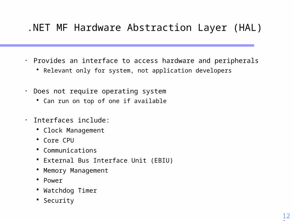
.NET MF Hardware Abstraction Layer (HAL)
• Provides an interface to access hardware and peripherals Relevant only for system, not application developers
• Does not require operating system Can run on top of one if available
• Interfaces include: Clock Management Core CPU Communications External Bus Interface Unit (EBIU) Memory Management Power Watchdog Timer Security

122
.NET MF Platform Abstraction Layer (PAL)
• Provides hardware independent abstractions Used by application developers to access system resources Application calls to PAL managed by Common Language Runtime (CLR) In turn calls HAL drivers to access hardware
• PAL interfaces include: Time PAL Memory Management Input/Output Events Debugging Storage PAL Communications Asynchronous Procedure Call Bootstrap

123
Threading Model
• User applications may have multiple threads
Represented in the system as Managed Threads serviced by the CLR
Time sliced context switching with (configurable) 20ms quantum
Threads may have priorities
• CLR has a single thread of execution at the system level
Uses cooperative multitasking
Explicitly yields execution periodically to interrupt service routine continuations
124
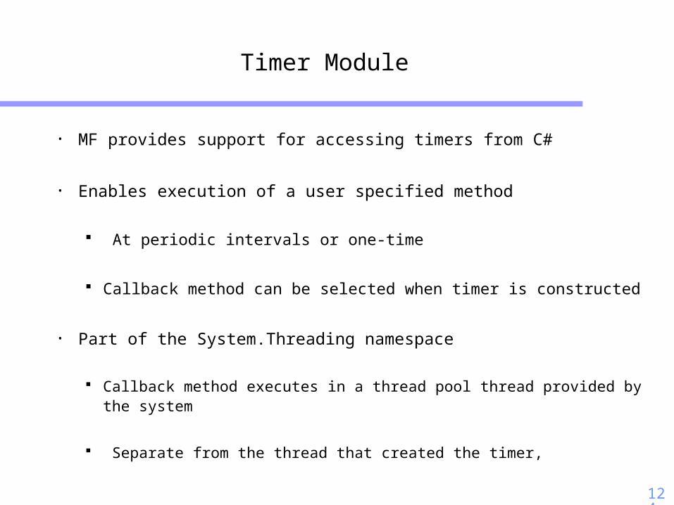
Timer Module
• MF provides support for accessing timers from C#
• Enables execution of a user specified method
At periodic intervals or one-time
Callback method can be selected when timer is constructed
• Part of the System.Threading namespace
Callback method executes in a thread pool thread provided by the system
Separate from the thread that created the timer,

125
Timer Interface
• Callback: user specified method to be executed
• State: information used by callback method May be null
• Duetime: delay before the timer first fires
• Period: time interval between callback invocations
• Change method allows user to stop timer Change period to -1

126
ADC Extension to the HAL
• Extended MF HAL to support ADC API’s High-precision, low latency sampling using hardware clock
Critical for many signal processing applications
• Supported API functions include Initialize: initialize ADC peripheral registers and the clocks
UnInitialize: reset ADC peripheral registers and uninitialize clocks
ConfigureADC: select ADC parameters (mode, input channels, etc)
StartSampling: starts conversion on selected ADC channel
GetSamplingStatus: whether in progress or complete
GetData: returns data stored in ADC data register

127
Radio Extension to the HAL
• Extended the MF HAL to support radio API’s
• Supported API functions include On: powers on radio, configures registers, SPI bus, initializes clocks
Off: powers off radio, resets registers, clocks and SPI bus
Configure: sets radio options for 802.15.4 radio
BuildFrame: constructs data frame with specified parameters
destination address, data, ack request
SendPacket: sends data frame to specified address
ReceivePacket: receives packet from a specified source address

128
MAC Extension to PAL
• Built-in, efficient wireless communication protocol
OMAC (Cao, Parker, Arora: ICNP 2006) Receiver centric MAC protocol Highly efficient for low duty cycle applications
Implemented as a PAL component natively on top of HAL radio extensions for maximum efficiency
Exposes rich set of wireless communication interfaces OMACSender OMACReceiver OMACBroadcast
Easy, out-of-the-box Wireless Communication Complete abstraction of native, platform or protocol specific code
from application developers