
LECTURE # 13 - KSUfac.ksu.edu.sa/sites/default/files/chapter_5_lectures.pdf · Equation can...
46
LECTURE # 13 Chapter 5 (Session #1): Mass and Energy Analysis of Control Volumes Copyright Hany A. Al-Ansary and S. I. Abdel-Khalik (2014) 1
Transcript of LECTURE # 13 - KSUfac.ksu.edu.sa/sites/default/files/chapter_5_lectures.pdf · Equation can...

LECTURE # 13
Chapter 5 (Session #1):
Mass and Energy Analysis of
Control Volumes
Copyright Hany A. Al-Ansary and
S. I. Abdel-Khalik (2014) 1

CHAPTER 5
MASS AND ENERGY ANALYSIS
OF CONTROL VOLUMES
Copyright Hany A. Al-Ansary and
S. I. Abdel-Khalik (2014) 2

CHAPTER 5 -- Mass and Energy
Analysis of Control Volumes
OUTCOME: Develop and Apply the conservation of mass principle to
both steady and unsteady control volumes.
Identify the energy carried by a fluid stream crossing a control surface.
Develop and Apply the conservation of energy principle to control volumes
Solve energy balance problems for steady flow devices.
Apply energy balance to unsteady flow processes with emphasis on the uniform-flow process.
Copyright Hany A. Al-Ansary and
S. I. Abdel-Khalik (2014) 3
Copyright Hany A. Al-Ansary and
S. I. Abdel-Khalik (2014) 4
CONSERVATION OF MASS
Mass is conserved -- it cannot be created or destroyed
Relativistic effects are ignored since minute changes in mass are beyond precision of engineering measurements
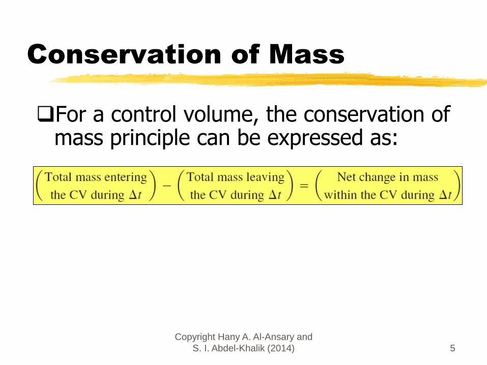
Conservation of Mass
For a control volume, the conservation of mass principle can be expressed as:
Copyright Hany A. Al-Ansary and
S. I. Abdel-Khalik (2014) 5
Copyright Hany A. Al-Ansary and
S. I. Abdel-Khalik (2014) 6
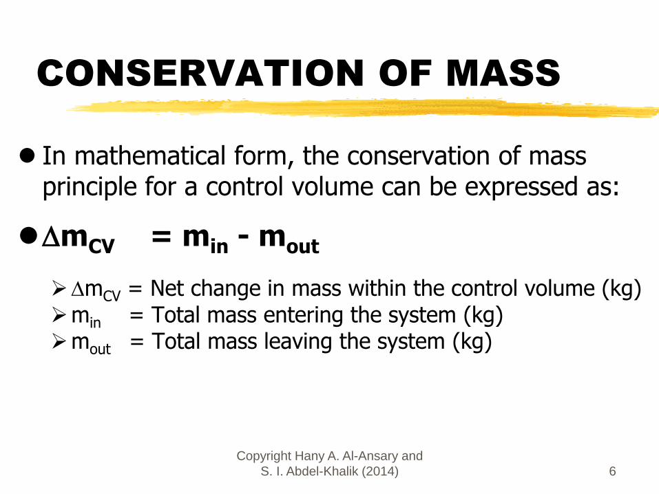
CONSERVATION OF MASS
In mathematical form, the conservation of mass principle for a control volume can be expressed as:
mCV = min - mout
mCV = Net change in mass within the control volume (kg) min = Total mass entering the system (kg) mout = Total mass leaving the system (kg)

Conservation of Mass
Copyright Hany A. Al-Ansary and
S. I. Abdel-Khalik (2014) 7
Copyright Hany A. Al-Ansary and
S. I. Abdel-Khalik (2014) 8
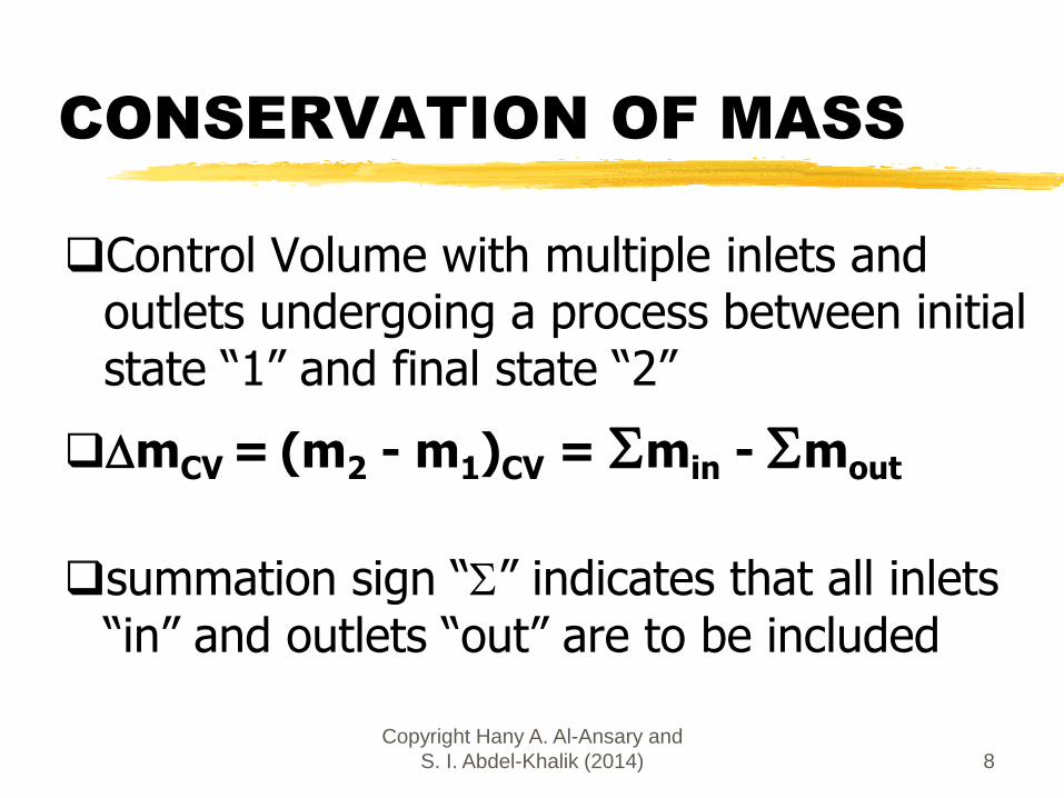
CONSERVATION OF MASS
Control Volume with multiple inlets and outlets undergoing a process between initial state “1” and final state “2”
mCV = (m2 - m1)CV = min - mout
summation sign “” indicates that all inlets
“in” and outlets “out” are to be included
Copyright Hany A. Al-Ansary and
S. I. Abdel-Khalik (2014) 9
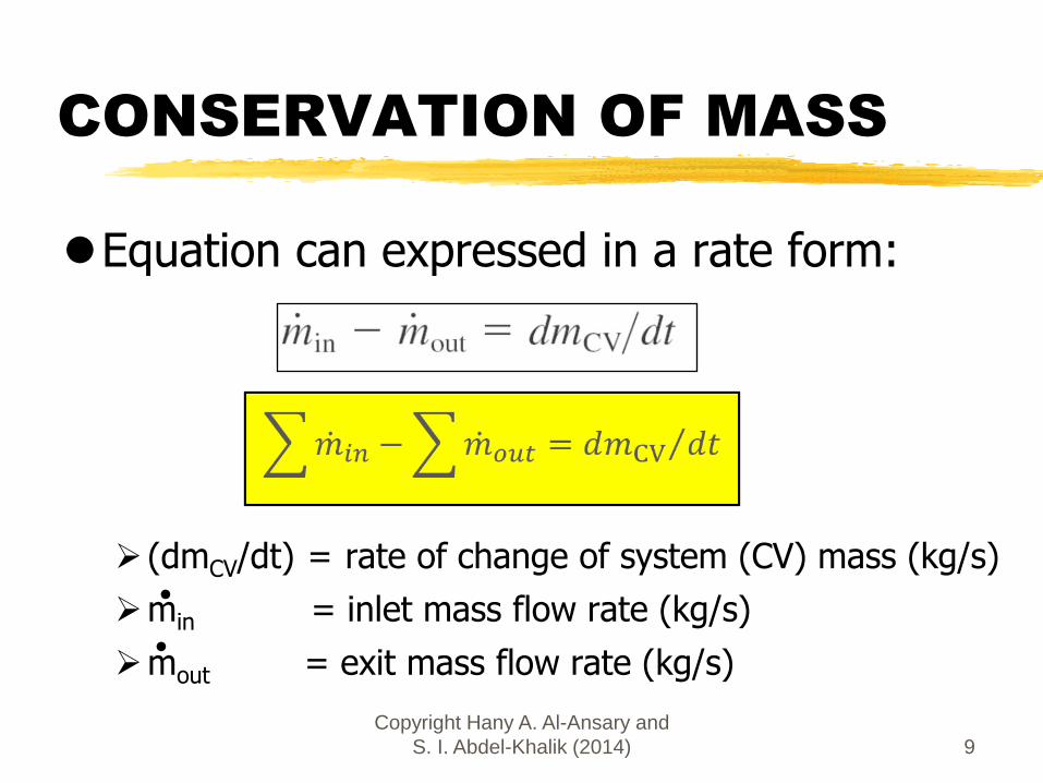
CONSERVATION OF MASS
Equation can expressed in a rate form:
(dmCV/dt) = rate of change of system (CV) mass (kg/s)
min = inlet mass flow rate (kg/s)
mout = exit mass flow rate (kg/s)
. .

Copyright Hany A. Al-Ansary and
S. I. Abdel-Khalik (2014) 10
Control Volume Mass
For uniform density
mCV = V
For non-uniform density
mCV = dV
CV
Copyright Hany A. Al-Ansary and
S. I. Abdel-Khalik (2014) 11
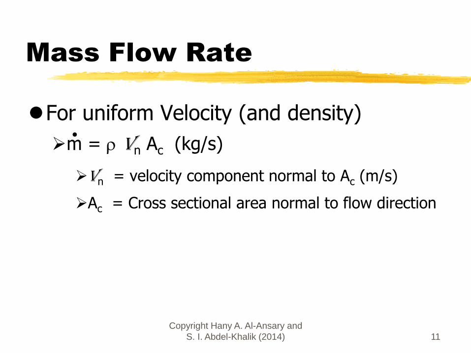
Mass Flow Rate
For uniform Velocity (and density)
m = Vn Ac (kg/s)
Vn = velocity component normal to Ac (m/s)
Ac = Cross sectional area normal to flow direction
.

Mass Flow Rate
For Non-Uniform velocity:
For uniform density this can be written as
Where Vavg is the average velocity
Copyright Hany A. Al-Ansary and
S. I. Abdel-Khalik (2014) 12

Copyright Hany A. Al-Ansary and
S. I. Abdel-Khalik (2014) 13
Volumetric Flow Rate
For uniform Velocity
V = Vn Ac (m3/s) = m / ρ = m v
For non-uniform Velocity
V = Ac Vn dAc (m3/s)
V = Vavg Ac
Vavg (m/s) = Average fluid velocity normal to A
Ac (m2) = cross sectional area normal to flow
direction
. . .
.
.

Copyright Hany A. Al-Ansary and
S. I. Abdel-Khalik (2014) 14
Total Energy of a Flowing
Fluid
For a closed system: the energy per unit mass: e = u + V2/2 + g z (kJ/kg)
For an open system: mass crosses the boundary Each unit mass crossing the boundary has total
energy: e = u + V2/2 + g z (kJ/kg)
In addition, when mass crosses a system boundary, work is done to move that mass across the boundary. This is referred to as “Flow work”

FLOW WORK
Flow work, or flow energy is the work (or energy) required to “push” the mass into or out of the control volume.
This work is necessary for maintaining a continuous flow through a control volume.
Copyright Hany A. Al-Ansary and
S. I. Abdel-Khalik (2014) 15
Flow Work per unit mass
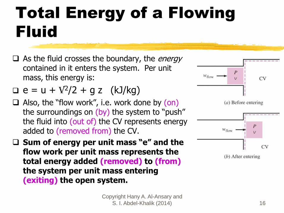
Total Energy of a Flowing
Fluid
As the fluid crosses the boundary, the energy contained in it enters the system. Per unit mass, this energy is:
e = u + V2/2 + g z (kJ/kg)
Also, the “flow work”, i.e. work done by (on) the surroundings on (by) the system to “push” the fluid into (out of) the CV represents energy added to (removed from) the CV.
Sum of energy per unit mass “e” and the flow work per unit mass represents the total energy added (removed) to (from) the system per unit mass entering (exiting) the open system.
Copyright Hany A. Al-Ansary and
S. I. Abdel-Khalik (2014) 16
Copyright Hany A. Al-Ansary and
S. I. Abdel-Khalik (2014) 17
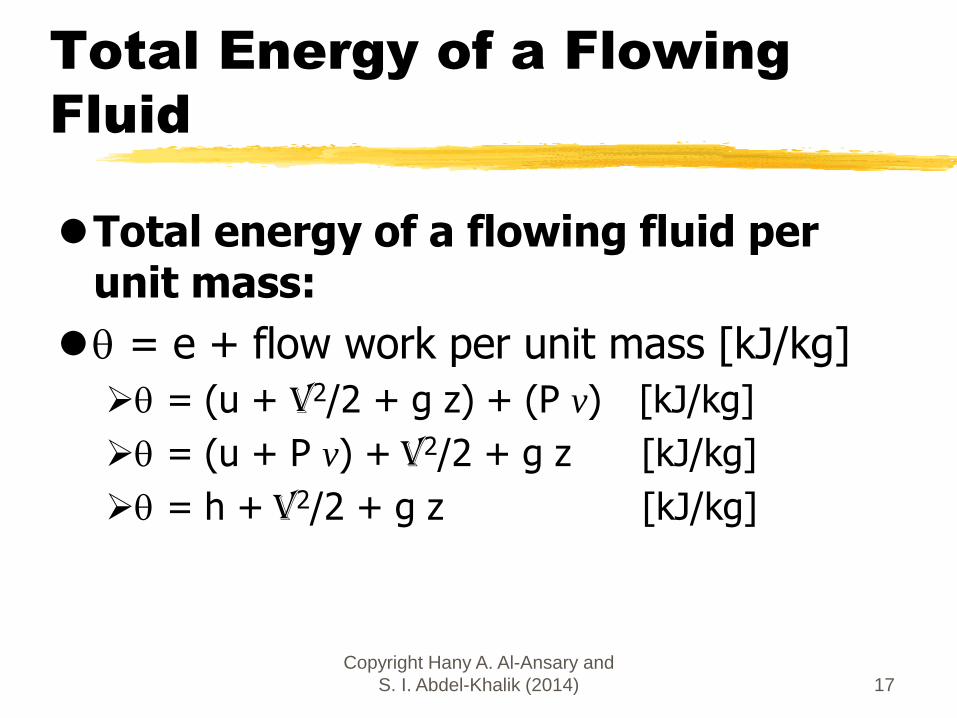
Total Energy of a Flowing
Fluid
Total energy of a flowing fluid per unit mass:
= e + flow work per unit mass [kJ/kg]
= (u + V2/2 + g z) + (P v) [kJ/kg]
= (u + P v) + V2/2 + g z [kJ/kg]
= h + V2/2 + g z [kJ/kg]
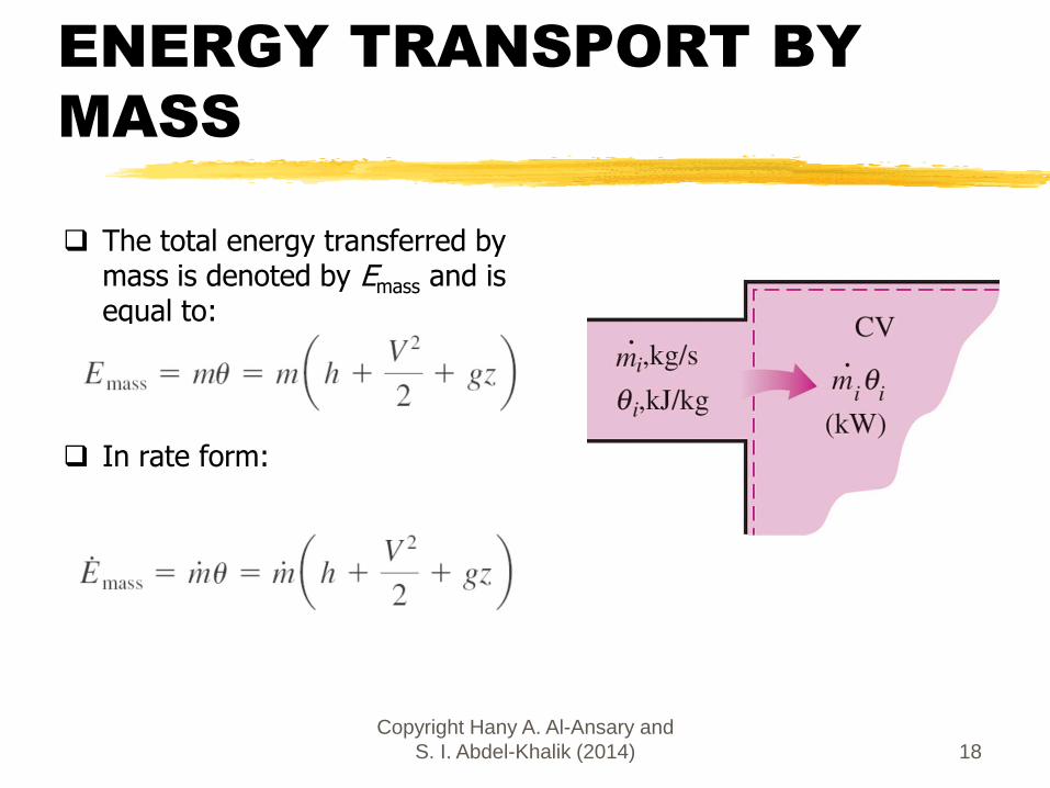
ENERGY TRANSPORT BY
MASS
The total energy transferred by mass is denoted by Emass and is equal to:
In rate form:
Copyright Hany A. Al-Ansary and
S. I. Abdel-Khalik (2014) 18

The First Law of Thermodynamics
for Open Systems
Copyright Hany A. Al-Ansary and
S. I. Abdel-Khalik (2014) 19

Mass Balance for Steady-
Flow Processes
Steady flow no change with time
(dmCV/dt) = 0
Conservation of mass reduces to:
If there is only a single inlet and single outlet
Copyright Hany A. Al-Ansary and
S. I. Abdel-Khalik (2014) 20

Copyright Hany A. Al-Ansary and
S. I. Abdel-Khalik (2014) 21
Mass Balance for Steady
Incompressible Flow Processes
Incompressible Flow: A flow in which the specific volume (and density) remain constant.
The conservation of mass relations can be simplified even further when the fluid is incompressible, which is usually the case for liquids.
Steady, incompressible Flow
Steady, incompressible Flow (Single Stream)

Energy Balance for Steady-
Flow Processes
Steady flow no change with time
(dECV/dt) = 0
Conservation of energy reduces to:
Copyright Hany A. Al-Ansary and
S. I. Abdel-Khalik (2014) 22

Some Steady-Flow
Engineering Devices
Many engineering devices operate steadily for long periods of time -- Conditions at different points in the system are different but they do not change with time.
Examples: turbines, compressors, nozzles, heat exchangers, pumps.
These devices can be conveniently analyzed as steady-flow devices.
Application of the first law (energy balance) to some of these devices will be presented:
Turbines and compressors
Throttling valves
Heat exchangers
Copyright Hany A. Al-Ansary and
S. I. Abdel-Khalik (2014) 23
Steady-Flow Engineering
Devices -- Example
Copyright Hany A. Al-Ansary and
S. I. Abdel-Khalik (2014) 24
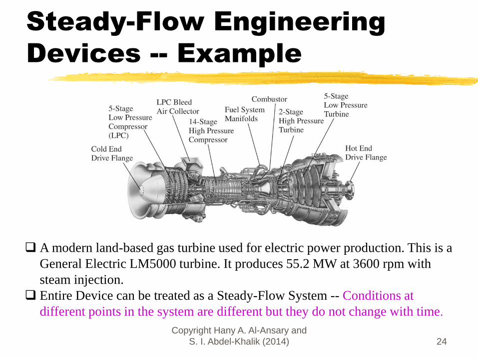
A modern land-based gas turbine used for electric power production. This is a
General Electric LM5000 turbine. It produces 55.2 MW at 3600 rpm with
steam injection.
Entire Device can be treated as a Steady-Flow System -- Conditions at
different points in the system are different but they do not change with time.
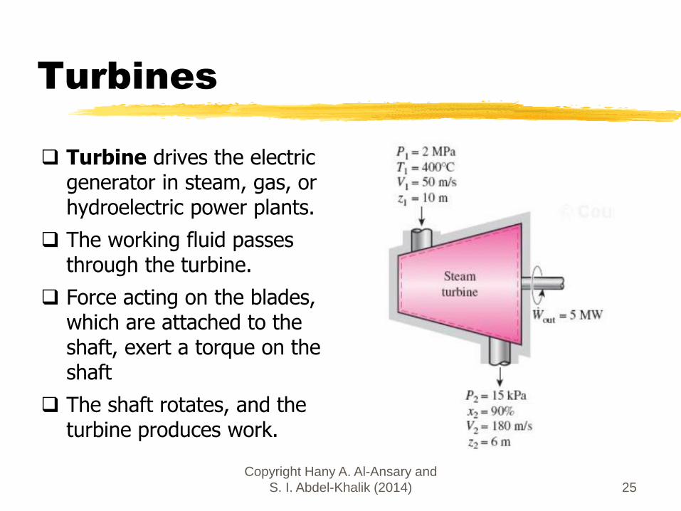
Turbines
Turbine drives the electric generator in steam, gas, or hydroelectric power plants.
The working fluid passes through the turbine.
Force acting on the blades, which are attached to the shaft, exert a torque on the shaft
The shaft rotates, and the turbine produces work.
Copyright Hany A. Al-Ansary and
S. I. Abdel-Khalik (2014) 25
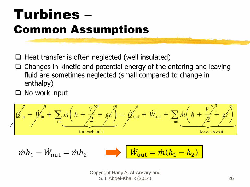
Turbines –
Common Assumptions
Heat transfer is often neglected (well insulated)
Changes in kinetic and potential energy of the entering and leaving fluid are sometimes neglected (small compared to change in enthalpy)
No work input
Copyright Hany A. Al-Ansary and
S. I. Abdel-Khalik (2014) 26
LECTURE # 14
Chapter 5 (Session #2):
Mass and Energy Analysis of
Control Volumes
Copyright Hany A. Al-Ansary and
S. I. Abdel-Khalik (2014) 27
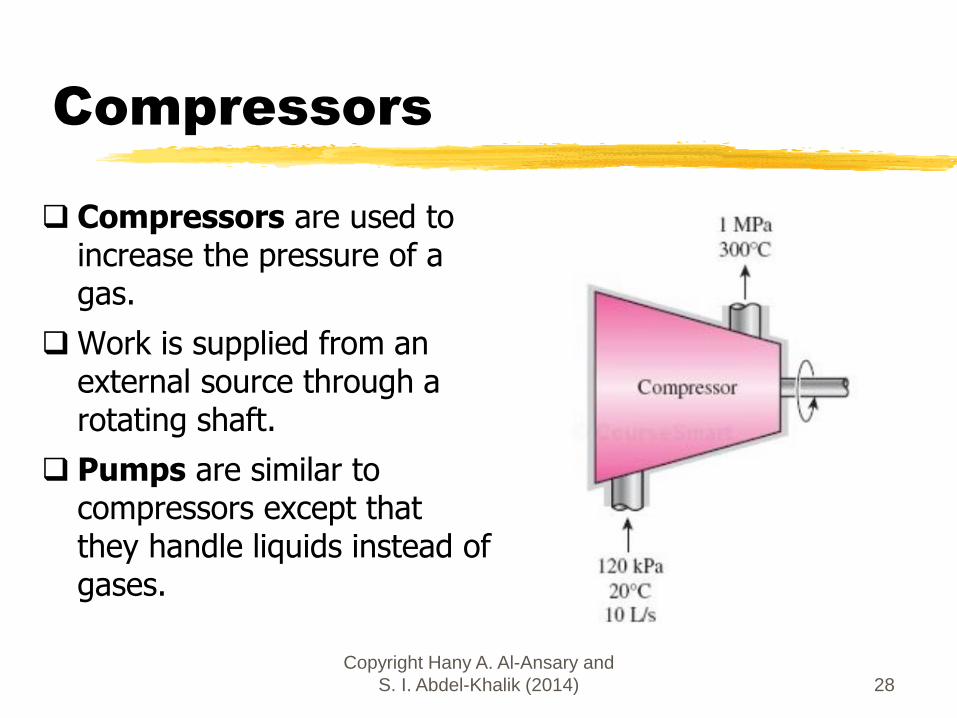
Compressors
Compressors are used to increase the pressure of a gas.
Work is supplied from an external source through a rotating shaft.
Pumps are similar to compressors except that they handle liquids instead of gases.
Copyright Hany A. Al-Ansary and
S. I. Abdel-Khalik (2014) 28

Compressors –
Common Assumptions
Heat transfer is often neglected (well insulated)
Changes in kinetic and potential energy of the entering and leaving fluid are sometimes neglected
No work output
Copyright Hany A. Al-Ansary and
S. I. Abdel-Khalik (2014) 29
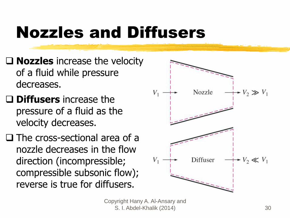
Nozzles and Diffusers
Nozzles increase the velocity of a fluid while pressure decreases.
Diffusers increase the pressure of a fluid as the velocity decreases.
The cross-sectional area of a nozzle decreases in the flow direction (incompressible; compressible subsonic flow); reverse is true for diffusers.
Copyright Hany A. Al-Ansary and
S. I. Abdel-Khalik (2014) 30
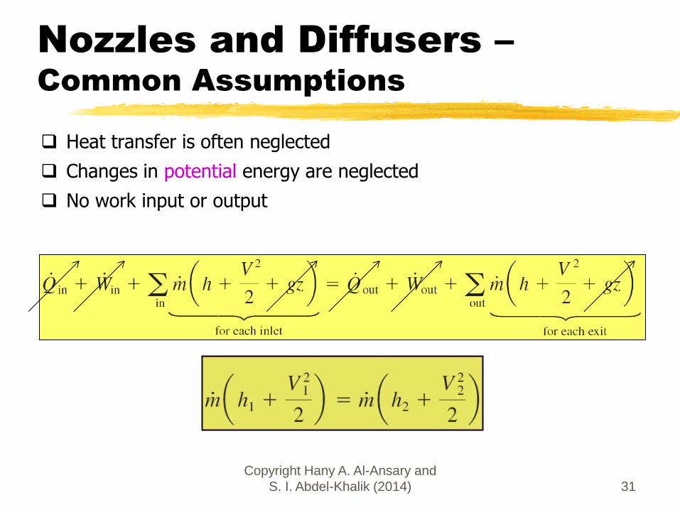
Nozzles and Diffusers –
Common Assumptions
Heat transfer is often neglected
Changes in potential energy are neglected
No work input or output
Copyright Hany A. Al-Ansary and
S. I. Abdel-Khalik (2014) 31
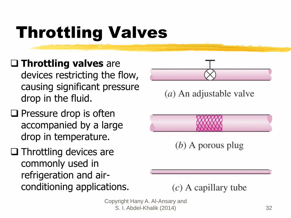
Throttling Valves
Throttling valves are devices restricting the flow, causing significant pressure drop in the fluid.
Pressure drop is often accompanied by a large drop in temperature.
Throttling devices are commonly used in refrigeration and air-conditioning applications.
Copyright Hany A. Al-Ansary and
S. I. Abdel-Khalik (2014) 32

Throttling Valves –
Common Assumptions
heat transfer is often neglected
Changes in kinetic and potential energy of the entering and leaving fluid are usually neglected
No work input or output
Copyright Hany A. Al-Ansary and
S. I. Abdel-Khalik (2014) 33
Isenthalpic Process

Mixing Chambers
Copyright Hany A. Al-Ansary and
S. I. Abdel-Khalik (2014) 34
In Engineering applications, the section where the mixing process of two (or more) streams takes place is referred to as a mixing chamber

Mixing Chambers –
Common Assumptions
Heat transfer is often neglected
Changes in kinetic and potential energy usually neglected
No work input or output
Copyright Hany A. Al-Ansary and
S. I. Abdel-Khalik (2014) 35

Heat Exchangers
Heat exchangers are devices where two moving fluid streams exchange heat without mixing.
Heat exchangers are widely used in various industries.
In refrigeration, the condenser and evaporator are heat exchangers.
Copyright Hany A. Al-Ansary and
S. I. Abdel-Khalik (2014) 36
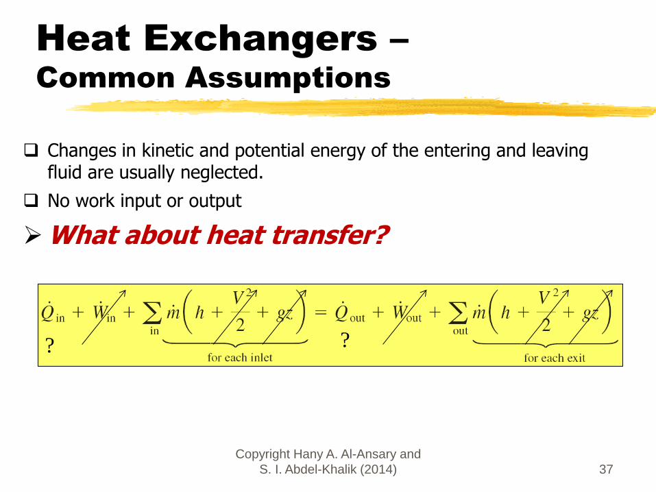
Heat Exchangers –
Common Assumptions
Changes in kinetic and potential energy of the entering and leaving fluid are usually neglected.
No work input or output
What about heat transfer?
Copyright Hany A. Al-Ansary and
S. I. Abdel-Khalik (2014) 37
? ?

If the entire heat exchanger is selected as the control volume (case a); heat exchange with the surroundings is negligible
In Case (b), the tube(s) alone is selected as the control volume; heat exchange cannot be neglected; heat is transferred from (to) fluid B to (from) fluid A depending on which fluid is hotter
What is Qout for fluid B?
Copyright Hany A. Al-Ansary and
S. I. Abdel-Khalik (2014) 38
Heat Exchangers –
Common Assumptions
1
1
2
2
3
3
4
4
.

Pipe and Duct Flow
Transport of liquids or gases in pipes and ducts is important in many engineering applications.
Flow through a pipe or a duct usually satisfies the steady-flow conditions. Changes in KE and PE can often be neglected
Copyright Hany A. Al-Ansary and
S. I. Abdel-Khalik (2014) 39
More than one form of work can be involved at the same time
Heat loss from fluid flowing in an uninsulated pipe can be significant

Pipe and Duct Flow
Example
Copyright Hany A. Al-Ansary and
S. I. Abdel-Khalik (2014) 40

Energy Analysis of
Unsteady Flow Processes
Many processes of interest involve changes within the control volume with time. Such processes are called unsteady-flow, or transient-flow, processes.
Copyright Hany A. Al-Ansary and
S. I. Abdel-Khalik (2014) 41
Charging of a tank from a supply line is an unsteady-flow process since conditions within the control volume change with time.
The shape and size of a control volume may change during an unsteady-flow process.
Unsteady, Uniform-Flow,
Process
Many unsteady-flow processes can be represented reasonably well by the uniform-flow process approximation.
Uniform-flow process: The fluid flow at any inlet or exit is uniform and steady, and thus the fluid properties do not change with time or position over the cross section of an inlet or exit. If they do, they are averaged and treated as constants for the entire process.
Copyright Hany A. Al-Ansary and
S. I. Abdel-Khalik (2014) 42

Mass & Energy Balances –
Unsteady Flow Processes
Mass Balance:
Copyright Hany A. Al-Ansary and
S. I. Abdel-Khalik (2014) 43

Mass & Energy Balances –
Unsteady Flow Processes
Energy Balance
For a Uniform-Flow Process
in and out do not change with time
Copyright Hany A. Al-Ansary and
S. I. Abdel-Khalik (2014) 44

Uniform-Flow Processes
Copyright Hany A. Al-Ansary and
S. I. Abdel-Khalik (2014) 45
A uniform-flow system may involve electrical, shaft, and boundary work all at once
The energy equation of a uniform-flow system reduces to that of a closed system when all the inlets and exits are closed.

CHAPTER 5 -- Mass and Energy
Analysis of Control Volumes
OUTCOME: Develop and Apply the conservation of mass principle to
both steady and unsteady control volumes.
Identify the energy carried by a fluid stream crossing a control surface.
Develop and Apply the conservation of energy principle to control volumes
Solve energy balance problems for steady flow devices.
Apply energy balance to unsteady flow processes with emphasis on the uniform-flow process.
Copyright Hany A. Al-Ansary and
S. I. Abdel-Khalik (2014) 46


![Exp 03 - Reaction Rate - Chemchem.ws/dl-1026/exp03-rate.pdf · (Rate law determination of the Crystal Violet reaction using the isolation method.) ... 1. conc. ( [CV] ) 2. log conc.](https://static.fdocuments.in/doc/165x107/5eb8a730d0b2f01a0a726335/exp-03-reaction-rate-rate-law-determination-of-the-crystal-violet-reaction.jpg)