Learning Objectives -...
55
Automate Your Curtain Wall, Window, and Building Product Design with Autodesk® Inventor® Joe Bartels – Enclos Corp Bill Graham – Enclos Corp ME3984 Curtain wall, window, and building product design walk the line between manufacturing and architectural design. This class will show how Autodesk Inventor can bridge the gap between disciplines to design your products for manufacturing. You will learn how the frame generator, iCopy, content library, and iLogic functionality will improve your design process. Learning Objectives At the end of this class, you will be able to: Use the features in Inventor that are suited for curtain wall, window, and building product design Configure and use the frame generator and content libraries Create and use iCopy assemblies Augment your design with iLogic programming
-
Upload
nguyentuyen -
Category
Documents
-
view
215 -
download
0
Transcript of Learning Objectives -...
Automate Your Curtain Wall, Window, and Building Product Design with Autodesk® Inventor®Joe Bartels – Enclos CorpBill Graham – Enclos Corp
ME3984
Curtain wall, window, and building product design walk the line between manufacturing and architectural design. This class will show how Autodesk Inventor can bridge the gap between disciplines to design your products for manufacturing. You will learn how the frame generator, iCopy, content library, and iLogic functionality will improve your design process.
Learning ObjectivesAt the end of this class, you will be able to:
Use the features in Inventor that are suited for curtain wall, window, and building product design
Configure and use the frame generator and content libraries
Create and use iCopy assemblies
Augment your design with iLogic programming

Automate Your Curtain Wall, Window, and Building Product Design with Autodesk® Inventor®
About the SpeakerJoe Bartels is a Technical Project Manager for Enclos Corp in Eagan, Minnesota. He is an Autodesk certified instructor, Autodesk certified expert, and an Autodesk Manufacturing solutions implementation certified expert. Joe has 11 years of design experience along with providing Autodesk Manufacturing CAD training, technical support, as well as professional services, including needs analysis, software implementation, product demonstrations, and software troubleshooting. Through the years, Joe has been published in Cadalyst, presented at numerous live and web presentations, and was awarded the Application Engineer of the Year and the 5 to 1 level 5 award from Autodesk.
Email: [email protected]
Twitter: josephbartels
Bill Graham is an Inventor Designer for Enclos Corp in Eagan, Minnesota. He is an Autodesk certified instructor, Autodesk certified expert, and an Autodesk Manufacturing solutions implementation certified expert. After graduating with a BS in mechanical engineering from Iowa State University, Bill acquired 11 years of design experience along with Autodesk Manufacturing CAD training and technical support. Bill has worked with numerous companies helping them to streamline their design processes and been published by Cadalyst. Key software technologies used over the years include the Inventor family of products, Vault family of products, and AutoCAD Electrical.
Email: [email protected]
2

Automate Your Curtain Wall, Window, and Building Product Design with Autodesk® Inventor®
IntroductionCurtain Wall, Window, and Building Products fabricators walk the gray area of architecture and manufacturing. They have to work with architects and provide them the products and designs in a format that works for them. On the other hand they have to manufacture their products and supply the fabrication shop drawings and models in a format that they can use.
In traditional 2D modeling AutoCAD is used to supply the drawings for architects and manufacturing. Building product manufacturers would typically have custom tools and templates set up in AutoCAD to handle the different disciplines.
With the advent of BIM initiatives and 3D modeling over the past few years there are different demands for building product manufacturers. They have to supply architects and general contractors with 3D Revit and Navisworks models while still creating fabrication drawings. Revit is well suited for modeling at a macro scale. It isn’t well suited for creating models and drawings at a micro scale.
Autodesk© Inventor® is a solid modeling program focused on generating 2D and 3D models for manufacturing. It has automated tools and environments to speed up the process of making models. While Revit is focused on drawing buildings at a macro scale, Inventor is focused on drawing models at a micro scale. The following images shows an example of a building modeled in Revit, while a window unit is modeled in Inventor. Inventor has every hole, notch, and part that makes up the window unit. Revit models every unit but in a simplified level of detail for performance reasons.
Revit (Macro) Inventor (Micro)
On any large scale project there will be thousands of parts and assemblies to model and detail. In Inventor this would mean that every part would have to be modeled, constrained in an assembly, and detailed in a drawing. This process will take months or years to finish using
3

Automate Your Curtain Wall, Window, and Building Product Design with Autodesk® Inventor®
traditional 3D modeling methods. Even a small increase in productivity can save a large amount of money over the course of a large project.
Inventor Productivity Tools for Building Products
Inventor has a wide variety of tools to aid in increasing 3D modeling. Not all of them are pertinent for modeling building products. This course focuses on three areas of functionality within Inventor that will automate building product design. The tools are:
Frame Generator and Content Library iCopy iLogic
All of the tools come with Inventor and don’t need any add-ons or upgraded packages.
Note that the tools that are covered are more than just a command. They encompass a method to create your models, configuring Inventor and the tools for your use when customizing Inventor to speed up your designs. The course describes the methods and best practices to use the tools, but each company has their own design challenges. Use this class to learn the tools and then apply it at your own company.
Frame Generator and Content LibrariesCurtainwall, window, and building product fabricators typically work with extruded aluminum and steel in their designs. The extrusions vary between standard steel shapes, aluminum mullions, 80-20, or piping.
The traditional method for creating extrusions involves drawing the profile, extruding, adding features, and constraining it into an assembly. This process takes time and none of the parts relate to each other. If the design changes all of the parts affected by the change have to be updated one by one.
The frame generator and the content libraries in Inventor give the end user the ability to quickly place extrusions into an assembly. The frame generator bypasses sketching, extruding, and constraining in an assembly. All of the components created by the frame generator will update if the design changes, making it easier to create variations of a design.
4

Automate Your Curtain Wall, Window, and Building Product Design with Autodesk® Inventor®
The frame generator uses a database of profiles and skeletal modeling to make it work. The content library and skeletal modeling process
The content library is a database of 700,000+ standard parts. The parts include bolts, nuts, washers, piping, hydraulics, bearings, and standard steel shapes. Inventor installs with a variety of content libraries based off of international standards (ANSI, ISO, DIN, etc). These standards are thorough but often need to be modified to meet company standards. Part numbers, file names, and descriptions usually need to be modified in the database so they are filled out correctly in BOM’s and titleblocks.
To modify standard parts, or to add your own parts, you need to have a custom content library. The process for modifying standard parts is to:
Create a custom content library. Activate the library in the project file. Copy the component definition into the custom library. Modify the component in the Content Editor.
The content library has two methods of delivery; Desktop Content or the Vault.
Desktop ContentDesktop Content is a single file on your network.
It is meant for a single user It is simple to use and deploy Easy to copy and send to other locations Only one user can modify No user management or control of who has access
5

Automate Your Curtain Wall, Window, and Building Product Design with Autodesk® Inventor®
VaultIt runs on a server along with the Vault, Vault Workgroup, Vault Collaboration, or Vault Professional
Meant for a workgroup Ability to replicate across multiple servers Multiple users can modify content Control access and permissions of users
Setting up and installing the Vault for the Content Library is beyond the scope of this class. For the rest of the course the Desktop Content is used.
Create a Custom Desktop Content Library
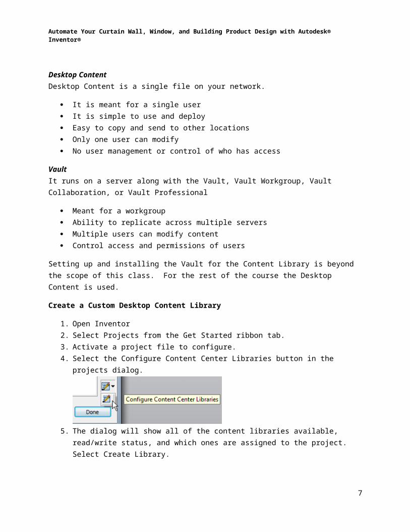
1. Open Inventor2. Select Projects from the Get Started ribbon tab.3. Activate a project file to configure.4. Select the Configure Content Center Libraries button in the projects dialog.
5. The dialog will show all of the content libraries available, read/write status, and which ones are assigned to the project. Select Create Library.
6
Automate Your Curtain Wall, Window, and Building Product Design with Autodesk® Inventor®
6. Enter a display name and file name. The file name cannot contain odd characters or spaces. Select OK.
7. Select the checkbox in the In Use column to make the library available. Select OK.
Setting Folder Structures in the Content Library
To publish to the content library, especially for the frame generator, a folder structure needs to be present. The easiest way is to copy the folder structure from an existing library to the custom library.
Copy Folder Structure Open Inventor. A custom content library needs to be available. Select Tools -> Content Center -> Content Center Editor Select a folder to copy. Right-click over the folder and select Copy Category Structure
To -> <Custom Content Library>. For frame generated parts it’s suggested to select the Structural Shapes folder.
The folder structure is copied to the custom content library. The folders will highlight when copied to show that the folder is read/write.
Create a Folder/Category Start the Content Center Editor from the Tools -> Content Center ribbon tab. In the Library View pulldown select the custom content library to add a folder to.
Select the Create Category button. Enter a name for the category. Select OK.
7

Automate Your Curtain Wall, Window, and Building Product Design with Autodesk® Inventor®
Publishing Frame Generator Components
Inventor has a utility, the Structural Shape Authoring tool, which will take your extrusion part, configure it, and publish it to the content library so it can be used with the frame generator.
How to publish a custom profile to the structural content library1. Create a new part file.2. Create a new sketch on the XY plane if one isn’t active. 3. Either draw a profile or copy and paste one from AutoCAD. For complex profiles that
won’t stretch it’s suggested to turn off sketch constraints. Align the profile to the origin. The origin point should represent the typical insertion point.
4. Extrude the profile a nominal distance. Change the extrusion length parameter to a named parameter (Ex: LENGTH= 12in).
5. Save the file.6. Select Manage -> Author -> Structural Shape.
7. Select a Category to publish the component to from the Category pulldown menu. If a
custom category isn’t available exit the dialog and create a custom folder/category described in Create a Folder/Category.
8

Automate Your Curtain Wall, Window, and Building Product Design with Autodesk® Inventor®
8. For Default Base Point pick the Select Geometry option. The base sketch visibility will appear. Select the origin point.
9. On the Parameter Mapping tab select the button next to Base Length. Select the named parameter of the extrusion length (ex: LENGTH).
10. Select OK to configure the part and exit the dialog. ORSelect Publish Now to publish the part to the content library.
11. Select a library and a language. Select Next12. Select a category to publish to. This should already be selected. Select Next13. Select a parameter for Base Length. This should already be selected. Select Next.14. Select a Table Column value and select the -> button. This is usually a part number or a
key column that is used to select a size. Select Next.
9

Automate Your Curtain Wall, Window, and Building Product Design with Autodesk® Inventor®
15. Enter a Family Name. The name will be what the user will choose from.16. Enter a Standard Organization. The end user will select this first. Give this a name after
the project, system, or family that the extrusion belongs to. Select Next.
10

Automate Your Curtain Wall, Window, and Building Product Design with Autodesk® Inventor®
17. Select Publish to add the profile to the content library.
Notes: Consider using AutoCAD to make extrusion profiles. A complicated extrusion can apply
too many constraints and dimensions. Either draw the profile in AutoCAD and copy it into a part file, or draw the geometry with the constraint persistence turned off.
Profile with dimensions and constraints Profile without dimensions and constraints
11

Automate Your Curtain Wall, Window, and Building Product Design with Autodesk® Inventor®
Create a block for the extrusion profile. It will make it easier to move and rotate. The block will also make it easier if you are doing 2D layouts.
Multibody in a frame generated partMultibodies are multiple solids defined within a single part file. Multibodies are useful for designing parts for an assembly together in a part file and then exporting them to an assembly. They can also be used for the following:
Including sealant or epoxy with a part file Small weldments Including gaskets with parts. Conceptual designs. Purchased components. Glass
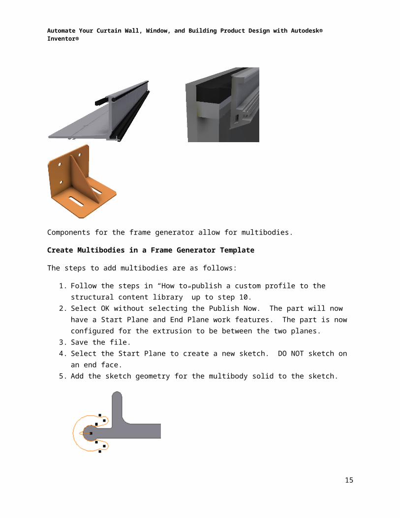
Components for the frame generator allow for multibodies.
Create Multibodies in a Frame Generator Template
The steps to add multibodies are as follows:
1. Follow the steps in “How to publish a custom profile to the structural content library” up to step 10.
2. Select OK without selecting the Publish Now. The part will now have a Start Plane and End Plane work features. The part is now configured for the extrusion to be between the two planes.
3. Save the file. 4. Select the Start Plane to create a new sketch. DO NOT sketch on an end face. 5. Add the sketch geometry for the multibody solid to the sketch.
12

Automate Your Curtain Wall, Window, and Building Product Design with Autodesk® Inventor®
6. Extrude the profile using the New Solid and Between options. Select the Start and End planes for the extrusion extents. This will ensure that the multibody will stretch with the original extrusion.
7. Optional: Select the solid body in the Solids folder. Right-click and select Properties. Change the color to differentiate between the solids.
8. Add additional multibodies as needed.9. Select Manage -> Author -> Structural Shape. Select Publish Now.10. Follow the steps in “How to publish a custom profile to the structural content library”
starting with step 11.
Notes: Multibodies will give you irregular weights. Different materials cannot get assigned to
solid bodies. In the Insert Frame dialog the preview of the profile will not show a preview of any solids
other than the initial solid.
13

Automate Your Curtain Wall, Window, and Building Product Design with Autodesk® Inventor®
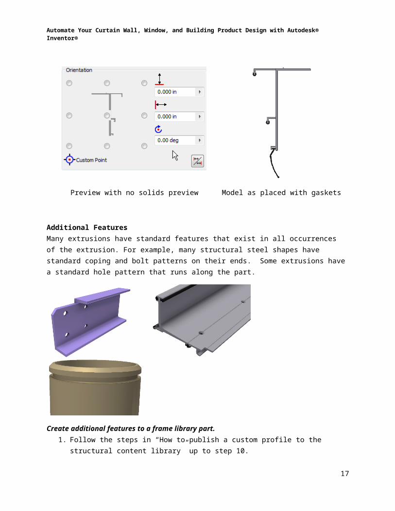
Preview with no solids preview Model as placed with gaskets
Additional FeaturesMany extrusions have standard features that exist in all occurrences of the extrusion. For example, many structural steel shapes have standard coping and bolt patterns on their ends. Some extrusions have a standard hole pattern that runs along the part.
Create additional features to a frame library part.1. Follow the steps in “How to publish a custom profile to the structural content library” up
to step 10. 2. Select OK without selecting the Publish Now. The part will now have a Start Plane and
End Plane work features. The part is now configured for the extrusion to be between the two planes.
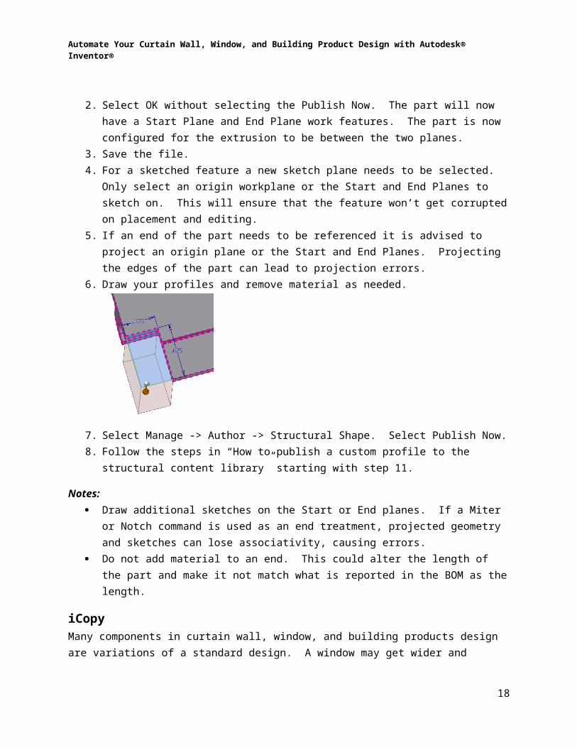
3. Save the file. 4. For a sketched feature a new sketch plane needs to be selected. Only select an origin
workplane or the Start and End Planes to sketch on. This will ensure that the feature won’t get corrupted on placement and editing.
5. If an end of the part needs to be referenced it is advised to project an origin plane or the Start and End Planes. Projecting the edges of the part can lead to projection errors.
6. Draw your profiles and remove material as needed.
14
Automate Your Curtain Wall, Window, and Building Product Design with Autodesk® Inventor®
7. Select Manage -> Author -> Structural Shape. Select Publish Now.8. Follow the steps in “How to publish a custom profile to the structural content library”
starting with step 11.
Notes: Draw additional sketches on the Start or End planes. If a Miter or Notch command is
used as an end treatment, projected geometry and sketches can lose associativity, causing errors.
Do not add material to an end. This could alter the length of the part and make it not match what is reported in the BOM as the length.
iCopyMany components in curtain wall, window, and building products design are variations of a standard design. A window may get wider and change hardware. A process tank may change in diameter. A skid could change in material and wall thickness.
15

Automate Your Curtain Wall, Window, and Building Product Design with Autodesk® Inventor®
A window changes height and intermediate dimensions
A processing tank changes diameter, height, number of inputs, and support columns.
For many types of products it is hard to predict how they need to be modified. The size of a part may be defined but the length and hole pattern will change on each assembly. A project may have hundreds of similar assemblies with various lengths. A huge amount of time could get spent copying assemblies, changing the parameters of the assembly, and constraining them into a general arrangement.
The following picture shows an instance where the same window design has different heights, widths, and part options on an elevation in a project.
iCopy is a tool that takes a configured assembly and allow it to stretch and change to fit into another assembly. iCopy does two functions, copies an assembly and then changes geometry and parameters to match the design intent.
iCopy needs a few things to work.
A skeletal part. This part is a referenced part that is stripped down to its bones. It may be a 2D sketch or a set of work points. This part needs to be adaptive. Generally the skeletal part should be a 2D sketch that is free to move. If the sketch changes, all of the parts in the iCopy assembly will move with it. All of the geometry and parameters that will change in the assembly have to be referenced to this part. This part can get linked to the other components through adaptivity, derived components, or iLogic.
16
Automate Your Curtain Wall, Window, and Building Product Design with Autodesk® Inventor®
A skeletal model iCopy assembly in its initial state
iCopy assembly after changing the skeletal part.
Links between files. For the components to change with the skeletal file links need to be made between the components and the skeletal file. The links could be created by:
o Derived Component – derive the skeletal part into the other components. The derived geometry and parameters are used to link the skeletal components together. From our experience this works. Once in a while the links will break when copying files.
o Adaptivity – Geometry is projected or linked by Copy Object into the components. Parameters aren’t linked, only geometry. Probably the easiest to set up, but the most unstable.
o iLogic – Link parameters between files using iLogic rules. No geometry is linked. As long as the files keep their labels in the assembly it is stable and flexible. iLogic is covered later in this course.
All three methods have their advantages and quirks. It’s possible to break the links using any of the methods, so testing of an iCopy model is important before releasing to production. From our experience a mixture of derived components and iLogic works the best.
Steps to create an iCopy assembly1. Start Inventor2. Create a new assembly file. Save the file.3. Create a new part file in the assembly. Mark the BOM structure of the part as
Reference. Name the file so that it marks the file as a skeletal file. (ex: Glass_Skeletal.ipt). Select OK. Select an assembly origin plane to start the part.
17
Automate Your Curtain Wall, Window, and Building Product Design with Autodesk® Inventor®
4. Unground the part. Constrain the part to the assembly template. If the part is grounded it will not work.
5. Draw geometry that is used to stretch the model in the skeletal part. Keep the input geometry in a single feature and visible. Any additional sketches and geometry should be placed in separate features and the visibility turned off.
6. Create user parameters to link to other components.
18

Automate Your Curtain Wall, Window, and Building Product Design with Autodesk® Inventor®
7. Return up to the top level assembly. Right-click on the skeletal part and select Adaptive. Save the skeletal file.
8. Create a part file for a new component.9. Either derive or project the skeletal file into the new component. Use the linked
geometry to start modeling the new component. Make links to skeletal parameters when geometry won’t do.
10. Create parts and subassemblies for the rest of the assembly. Link parts and assemblies to the skeletal model as needed. Constrain the parts to the assembly. Test the model by changing the skeletal model and viewing how the assembly changes.
19

Automate Your Curtain Wall, Window, and Building Product Design with Autodesk® Inventor®
11. Select iCopy Author from the Manage ribbon tab.
12. Select the skeletal part.
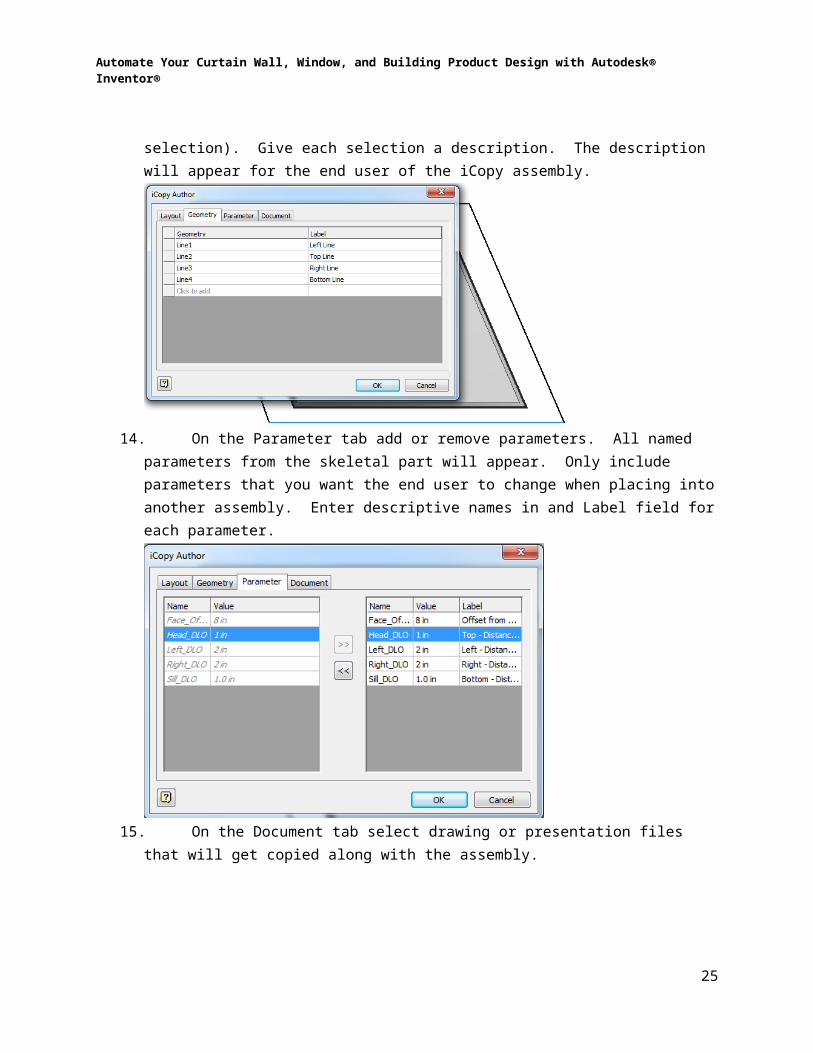
13. On the Geometry tab select geometry from the skeletal part that will stretch the assembly when placed in another assembly. Work geometry and 2D sketch geometry is valid for selection. 3D Sketch geometry isn’t. Select the geometry in a logical order for ease of use when placing in assemblies (ex: clockwise selection). Give each selection a description. The description will appear for the end user of the iCopy assembly.
14. On the Parameter tab add or remove parameters. All named parameters from the skeletal part will appear. Only include parameters that you want the end user to change when placing into another assembly. Enter descriptive names in and Label field for each parameter.
20

Automate Your Curtain Wall, Window, and Building Product Design with Autodesk® Inventor®
15. On the Document tab select drawing or presentation files that will get copied along with the assembly.
16. The iCopy settings are stored in the browser. Right-click on the feature and select Edit to edit the settings.
Place an iCopy Assembly1. Open an assembly that has geometry set up to place the iCopy assembly. The
geometry may be a skeletal layout file, or work geometry.
21

Automate Your Curtain Wall, Window, and Building Product Design with Autodesk® Inventor®
2. Select iCopy from the Assemble ribbon tab. Select an assembly that is configured for iCopy. Select Open.
3. Select geometry and enter parameters that are set up in the iCopy assembly. Select Next. If you get an error, cancel out of the dialog and look at the iCopy assembly for problems.
4. Select files to copy, reuse, or exclude. Notice that linked drawings and presentation files will also copy. Select Next.
22

Automate Your Curtain Wall, Window, and Building Product Design with Autodesk® Inventor®
5. Enter new file names and locations for components that are copied. Select OK.
6. The assembly will appear. The iCopy is nested in its own group in the browser. Right-click the iCopy icon in the browser and select Edit Using iCopy to modify parameters.
23

Automate Your Curtain Wall, Window, and Building Product Design with Autodesk® Inventor®
ParametersParameters are the source of design intent in an Inventor model. They control a model’s size, shape and position in an assembly. A firm understanding of how to use parameters is necessary to building robust Inventor models.
Types of parameters1. Model Parameters: The primary driving parameters within a model. Every time a
dimension or feature is created corresponding model parameters are created.2. Reference Parameters: Driven dimensions are the main source of reference
parameters. These parameters give a source of access to sizes that are not directly accessible from model examples. If two model extrusions work together to give the overall length for a part, a driven dimension can give the user the resulting length without the need to combine the extrusions sizes in an equation.
3. User Parameters: These are typically used to contain the design intent in a model. User parameters are not necessarily tied directly to a model dimension, but are typically used to drive model parameters via equations. User parameters are available in three different styles.
a. Numeric: Similar to most model dimension, but includes options other than length and angularity such as work or pressure
b. Text: This parameter option was added when iLogic was incorporated into the Inventor product family. Text allows entry of standard string values into model parameters. When used with the Multi-value option, this parameter provides a simply way to generate user friendly ways to enter data.
c. True/False: This is a standard Boolean operator the helps make basic decision making capabilities easier.
Exporting & FormattingExporting parameters has the following useful benefits:
1. Exported parameters are exposed as custom iProperties. Once they have been exported as an iProperty, they can be used in equations for other iProperties. This allows a model’s length width and height to be contained in a single iProperty.
2. Exported parameters are automatically exported when a model is derived into another model. This simplifies the process of linking two models together.
3. Exporting parameters allows for configuration of their display style. By default, Inventor will display 1’-6” as either 18 in or 1.5 ft depending on the unit specified for the parameter. If the desired format is 1’-6”, the parameter should be exported.
The process for exporting parameters is listed below
1. Open the parameters dialog box2. Select the Export Parameter check box next to the parameter to be exported
24
Automate Your Curtain Wall, Window, and Building Product Design with Autodesk® Inventor®
3. Right click anywhere along the line containing the parameter and select Custom Property Format… from the fly out.
4. Select the appropriate Property type (Text has the most options)
5. Configure the units6. Configure the format for decimal or fractional7. Establish precision8. Enable/Disable Leading zeros, trailing zeros and units string9. Apply to existing comparable parameters
25

Automate Your Curtain Wall, Window, and Building Product Design with Autodesk® Inventor®
Keys & Multi-valuesWhen building intelligent models, it is useful to minimize the amount of effort a user must exert to make changes to a model. A convenient method to accomplish this is to limit the number of options the user has when editing the model. Key and Multi-value parameters achieve these goals.
Key parameters allow a user to filter the available parameters a user sees when opening the parameter dialog box. The process for marking a parameter as a key follows
1. Open the parameters dialog box.2. Identify the key parameters a user will edit3. Check the key column of the appropriate parameters4. To filter the parameters list select the funnel shaped icon from the lower left corner of the
parameters dialog box and select Key from the list.
Multi-value parameters allow a user to limit the number of options available for a parameter. This can be either a fixed list or a list of suggested values. To configure a multi-value parameter follow the steps listed below.
1. Open the parameters dialog box2. Right click anywhere along the line containing the parameter and select Edit Multi-value
List… from the fly out.3. Type the list in the upper section of dialog box pressing enter to add additional values. 4. Select Add to move them to the list below. Note: Closing the dialog box before adding
will nullify the additions.5. If the user needs to enter values other than those created in step 4 above, select the
Allow custom value check box. When this check box is enabled values not listed may be entered into the parameter, but the default values will be limited to those in the dialog box.
iLogicILogic allows for the creation of rules based design. Inventor models and drawings can be updated based on changes in parameters or through the firing of events. Rules can be stored locally or globally. ILogic is broken into Forms and Rules to allow a flexible method to control configured models. These capabilities provided the foundation for building configured product lines. Capturing the tribal knowledge of a company and writing them into rules has the added benefit of decreasing design time and reducing errors. This document will provide a brief overview the Form Editor and Rule Editor along with a couple samples accomplishing typical tasks. ILogic contains a great variety of possible functions.
Typical uses for iLogic:
Change iPart and iAssembly components in an assembly Suppress or unsuppress features or components
26

Automate Your Curtain Wall, Window, and Building Product Design with Autodesk® Inventor®
Validating user input with regard to parameters, material selection or iProperties Updating BOM data Accessing sheet metal styles or flat pattern areas Reading and writing to Excel or XML Simplifying design selection criteria
This document will provide basic instruction on the use of some of the more common commands. If greater detail is necessary, it is recommended that users begin with the tutorial files provided with Inventor. The help menu offers additional detail on individual command coupled with example videos for many features.
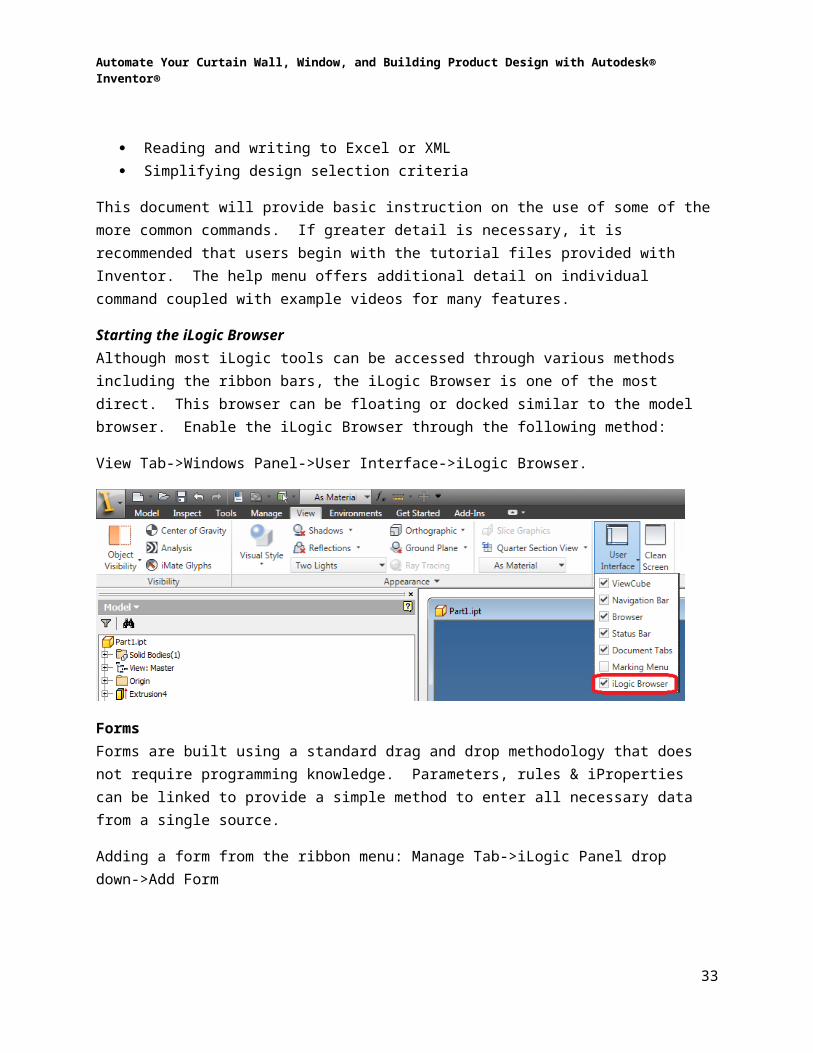
Starting the iLogic BrowserAlthough most iLogic tools can be accessed through various methods including the ribbon bars, the iLogic Browser is one of the most direct. This browser can be floating or docked similar to the model browser. Enable the iLogic Browser through the following method:
View Tab->Windows Panel->User Interface->iLogic Browser.
FormsForms are built using a standard drag and drop methodology that does not require programming knowledge. Parameters, rules & iProperties can be linked to provide a simple method to enter all necessary data from a single source.
Adding a form from the ribbon menu: Manage Tab->iLogic Panel drop down->Add Form
27

Automate Your Curtain Wall, Window, and Building Product Design with Autodesk® Inventor®
Adding a form from the iLogic browser: Right click on forms tab and select Add Form
Form Editor LayoutThe form editor has five major sections:
1. Filter: This simple tool will filter the parameters based on key or renamed condition. These key columns are the same setting established in the parameters portion of this document.
2. Tabs: Displays all the current parameters, rules and iProperties in a document3. Toolbox: Contains form components. These are primarily used for formatting purposes.4. Forms design tree: Displays the main body of the form being built. This is where the
forms shape is configured.5. Properties: Allows editing properties of individual components within the form.
28
Automate Your Curtain Wall, Window, and Building Product Design with Autodesk® Inventor®
Tabs ItemsThe tabs sections allow parameters, iProperties and rules to be dragged into a form. Parameters and iProperties are displayed as text with labels. These text boxes are converted to combo boxes when the parameter is a multi-value.
Toolbox ItemsThe following items are available for forms with a brief description of each.
1. Group: Groups items into a single collapsible grouping2. Tab: Create a single tab on the form. Drag multiple tab groups into the same level of a
form to create multiple tabs.3. Row: Create a single row to allow multiple pieces of data to be stored on a single row.4. Picture: Allows images to be inserted into a form5. Picture Folders: Provides a method for allowing alternate images to be displayed. This
is a storage method only. If multiple images are to be used, follow the steps that follow.a. Create a text user parameter with a multi-value list underneath itb. Start the Form Editorc. Insert a Pictured. Modify the behavior property of the picture to point to the parameter created in
step Ae. Add a picture folder with the appropriate number of pictures to encompass the
number of images desired. Additional pictures can be added to the folder if more than the standard 3 images are required.
f. Map the pictures in the picture folder the appropriate image on the networkg. Change the label of the picture to correspond with the appropriate parameter
value from the multi-value list specified in step a.6. Empty Space: Provides ability to space items7. Label: Simple text label for added information8. Splitters: Resizable splitter bar for the user interface
29

Automate Your Curtain Wall, Window, and Building Product Design with Autodesk® Inventor®
Typical Process for Building a Form1. Start the Form Editor by adding or editing a form.2. Drag necessary components from the toolbox/tabs sections. 3. Arrange the order of components in the form design tree. 4. Update component properties when necessary. These properties vary depending on the
type of component that was placed. Example properties include read only status and font. Labels should be updated at a minimum.
Note: Forms are built at runtime based on a top to bottom formatting of the information displayed in the Form Design Tree. Use the Preview button located at the bottom of the Form Editor to get a sample of the current form design.
RulesRules provide a simplified software coding environment to attach design intent into a model. Multiple rules may exist for a single document. Rules use check and control features, parameters and components. They are typically stored in the part, assembly or drawing file they are required for. Rules may be stored externally and details about this may be found in the help menu.
Adding a rule from the ribbon menu: Manage Tab->iLogic Panel->Add Rule
Adding a rule from the iLogic browser: Right click on Rules tab and select Add Rule
30

Automate Your Curtain Wall, Window, and Building Product Design with Autodesk® Inventor®
Edit Rule Dialog Box LayoutThe Edit Rule dialog box has five major sections;
1. The snippets section provides access to snippets of code that will be used to build rules. The system tab provides access to basic functions. The custom tab has larger pieces of pre-built code know as snippets. Functions and snippets can be brought into a rule by double clicking on an expanded node.
2. The model browser shows a model tree of the currently document. When an individual node is selected from the tree all driving parameters are shown under the parameter tab to the right of the tree.
3. The parameters/names tabs display the parameter names and current values based on those selected in the previous step.
4. Edit tools provides access to common editing tools such as copy, paste undo. It also provides access to conditional statements such as If…then…end if.
5. The main body of code is store in this section. Code can be entered into this section through a variety of methods. This includes selecting pieces of code from the snippets section, double clicking on parameters and selecting conditional standard from the edit tools.
Rule BasicsThe available options for writing rules are fairly extensive. These options include the ability to change parameters, iProperties or suppress features. This section will show how to accomplish some of the basic tasks necessary for writing rules. For the purposes of illustration, this document will focus on the automatic tools available in the Edit Rule dialog box for adding code. All code could be written manually as well.
31
Automate Your Curtain Wall, Window, and Building Product Design with Autodesk® Inventor®
Editing Parameters:
1. Start or edit a rule2. Locate the parameter in the model browser using a feature or the parameters collection.3. Double click on the parameter to bring it into the main body of the code. Alternatively,
select the parameter and right click on it to use the capture current state functionality. When capturing the current state, the parameter along with the current value is entered into the main body of code.
4. Complete the equation to specify the new value for the parameter.5. Select the OK button to fire the rule. The document may require an update to show
changes. Note: In the example shown the current value of Length and Width are 16 in, the rule will change these value 24 in
Typical uses for this function:
1. Push parameters from one part or assembly to others2. Check parameter sizes against maximum company allow values3. Reset parameters to baseline values
32
Automate Your Curtain Wall, Window, and Building Product Design with Autodesk® Inventor®
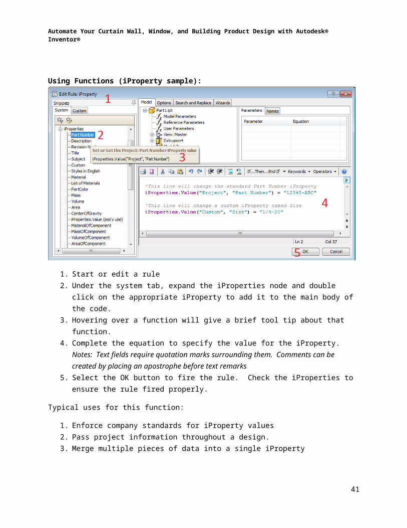
Using Functions (iProperty sample):
1. Start or edit a rule2. Under the system tab, expand the iProperties node and double click on the appropriate
iProperty to add it to the main body of the code.3. Hovering over a function will give a brief tool tip about that function.4. Complete the equation to specify the value for the iProperty. Notes: Text fields require
quotation marks surrounding them. Comments can be created by placing an apostrophe before text remarks
5. Select the OK button to fire the rule. Check the iProperties to ensure the rule fired properly.
Typical uses for this function:
1. Enforce company standards for iProperty values2. Pass project information throughout a design.3. Merge multiple pieces of data into a single iProperty
33

Automate Your Curtain Wall, Window, and Building Product Design with Autodesk® Inventor®
Conditional Statements:
1. Start or edit a rule2. Under the edit tools, select If…Then…End If and use the drop down button next to it to
add the Else statement. 3. Replace the “My_Expression” value in the If statement with an appropriate condition
statement. In the example shown, the rule will check to see if the Length parameter is greater than 24 and change a custom iProperty based on that test.
4. Add code to perform if the condition is true.5. Select the OK button to fire the rule.
Typical uses for this function:
1. Create design test2. Establish parameter limits3. Removed component or features if unnecessary at certain sizes
34

Automate Your Curtain Wall, Window, and Building Product Design with Autodesk® Inventor®
Component Suppression:
1. Start or edit a rule2. Locate the component to be suppressed in the model browser, right click and select
Capture Current State. Note: The name of the component corresponds with the browser node name. It is highly recommended that this name be changed from the default naming convention. Failure to rename browser nodes may cause the rule to fail if the design is copied
3. Change the equation to False to suppress the component4. Select OK to test the current code.
Typical uses for this function:
1. Remove component if unnecessary in certain designs2. Reduce user interaction to remove components3. Standardize design selection
35

Automate Your Curtain Wall, Window, and Building Product Design with Autodesk® Inventor®
Make Path Option:
1. Start or edit a rule2. Locate a function that ontains the MakePath option. Note: The MakePath option is very
powerful way to access parameters and features located in a subcomponent.3. Update the MakePath option argument to specify the path to the final component.
Separate each sub assembly level with a comma until the final component level has been reached. Change any other values necessary.
4. Select OK to test the current code.
Typical uses for this function:
1. Suppress components contained in a subassembly2. Pass parameter to components at various levels of an assembly3. Limit rules to a single top level location
36

Automate Your Curtain Wall, Window, and Building Product Design with Autodesk® Inventor®
Forms:
1. Start or edit a rule2. Locate a forms function and double click the style of form required. Note: Forms
launched as modal prevent interaction with the model and Inventor functions.3. Select OK to test the current code.
Typical uses for this function:
1. Fire forms at start up2. Ensure appropriate design criteria has been met prior to allowing files to be saved.3. Restrict ability to run any other Inventor function until a form has been filled out
37

Automate Your Curtain Wall, Window, and Building Product Design with Autodesk® Inventor®
Snippets:
1. Start or edit a rule2. Switch to the Custom Tab3. Locate the appropriate snippet from the tree and double click to add it to the Main Body.
Snippets are typically longer pieces of sample code.4. Update necessary options in the Main Body5. Select OK to test the current code.
Typical uses for this function:
1. Reduce the amount of coding that needs to be manually entered2. Save repetitive code to a convenient location.3. Standardize code formatting
38

Automate Your Curtain Wall, Window, and Building Product Design with Autodesk® Inventor®
Linking VBA/DLLs:
1. Start or edit a rule2. Select the appropriate function under Run Other / Advanced API and double click to add
it to the Main Body.3. Update the necessary options in the Main Body.4. Select OK to test the current code.
A sample was included with this class. This sample creates DXF files for every sheet metal part in an assembly. It only works at an assembly level. The example works by using a macro that expands the capability of iLogic. Warning: VBA created macros will not be available in the future. Converting to higher level .NET created code will avoid this issue.
Loading the sample macro:
1. Close all open documents2. Start the VBA editor (Tools Tab->Options Panel->VBA Editor3. Right click on the application project and select Import File… from the menu
39

Automate Your Curtain Wall, Window, and Building Product Design with Autodesk® Inventor®
4. Browse to and locate the DXF.bas file include with the example files5. Ensure the DXF file shows in the Modules folder located under the Application
Project.6. Start a new iLogic rule to an assembly file with sheet metal components7. Add the following line of code:
InventorVb.RunMacro("ApplicationProject", "DXF", "DXFCreation")8. Select OK to test the current code.
Typical uses for this function:
1. Expand the capability of iLogic2. Allow mixture of traditional and iLogic coding
40
Automate Your Curtain Wall, Window, and Building Product Design with Autodesk® Inventor®
Wizards:
1. Start or edit a rule2. Select the Wizards Tab3. Select the appropriate Wizard to run4. Update the necessary options in the dialog box and select OK to add the new code to
the Main Body5. Select OK to test the current code.
EventTriggersEvent Triggers fire the assigned rule after a certain event has occurred. The steps for assigning an event trigger are as follows.
1. Select Manage Tab->iLogic Panel->Event trigger2. Select the appropriate event trigger from the list. The available events are:
a. New Documentb. After Open Documentc. Before Save Documentd. After Save Documente. Close Documentf. Any Model Parameter Changeg. iProperty Changeh. Feature Suppression changei. Part Geometry Changej. Material Change
41

Automate Your Curtain Wall, Window, and Building Product Design with Autodesk® Inventor®
3. Pick the Rules button from the lower right side of the dialog box4. Place a check mark next to each rule which should be run by that event.5. Select the OK buttons to close the dialog boxes and test to ensure that the dialog boxes
work.
iLogic Components
ILogic components are unique Inventor components and subassemblies created from standard parts. Assemblies must be saved prior to placing an iLogic Component. After selecting an iLogic component to place into an assembly, the following occurs
1. A new copy of the component and saved to the same folder as the assembly.2. The new component is appended with a numeric suffix (-01, -02 etc.)3. A dialog box appears allowing a user to link parameters from the assembly to the
component.4. If parameters are linked, a new rule is added to the assembly to link the parameters.
iLogic Design CopyOnce a template iLogic model has been created, it is often necessary to create multiple independent versions. The new models will follow the same design rules, but may have different parameter input for a specific design. The following steps will build a new independent model.
1. Close all open file2. On the Tools Tab->iLogic Panel->Select iLogic Design copy3. Specify a source project4. Select the design to copy. Note: Always select the top level component of a design.
This is typically a drawing or assembly. Files referenced by this top level design will automatically be reference into the copy process.
42

Automate Your Curtain Wall, Window, and Building Product Design with Autodesk® Inventor®
5. Select any additional files to copy. This includes non-Inventor file such as Microsoft Excel or Inventor files such drawing files for parts underneath an assembly may not have been selected. Press Next to continue
6. Determine if a new project is required or the existing project can be used.7. Specify a new target folder for the new design.8. Add a new prefix and/or suffix for the new files.9. Specify the appropriate copy options
a. Delete Rules strips all rule information from the documents. This is useful when passing a design to users outside the company to preserve intellectual property.
b. If the Update Part Number box is check, the new files will have their part number iProperty changed to match the newly create file name.
ILogic Tips & TricksFollowing is a brief list of recommendations when using iLogic
1. Create a list of common parameters prior to beginning design2. Keep rules simple. Add more rules to create more complex designs3. Before adding code rename the browser nodes to establish consistent naming
a. Rename components in assembliesb. Rename feature in parts
4. Establish a custom LOD/Design View Representation in an assembly prior to suppressing components. ILogic will not change suppression levels on the Master LOD. Ensure the custom LOD is the active LOD
5. Add rules at a top level assembly. Use the MakePath function to pass parameters to lower level subassemblies and parts
6. If additional capabilities are needed beyond standard iLogic functions, use the API to expand those capabilities
ConclusionIn the rapidly changing world we live in, companies must find new methods to bring designs to a competitive market. Curtain Wall, Window, and Building Products fabricators have more to deal with than the simplified macro environments that Revit and Navisworks provide. Design of building products includes the micro environment of parts and subassemblies with BOM and fabrication drawings necessary to bring design to life. During the course of this document the some of the capabilities of Autodesk Inventor to bridge this gap between the macro and micro environment have been presented. The key functions shown have been Frame Generator, iCopy and iLogic.
Frame generator provides a simplified method to construct assemblies based on standard profile sections. Though a standard library ships with the software, custom profiles enhance the capability of a company to use proprietary profiles or tweak the display of information from a standard library. This document outlines the steps necessary to configure a new custom content library and publish profiles to that library. Options were demonstrated on the use of
43

Automate Your Curtain Wall, Window, and Building Product Design with Autodesk® Inventor®
multibodies and optional features. Multibodies can be used to represent gasketing material or sealant.
ICopy allows configured assemblies to be built. These configured products can then be stretched to fit the appropriate rough opening when the design calls for it. This document outlined the steps necessary to build an iCopy assembly along with providing recommendation for building robust models. The section concluded with the steps necessary to place an iCopy component.
ILogic provides a framework for building configured products in a variety of shapes and sizes. Configured products capture tribal knowledge within a company providing fast, accurate designs. This document outlined the basic capabilities contained within iLogic to build forms and rules. It outlined the steps necessary to begin building iLogic models. Methods to copy configured designs and expand iLogic capabilities using API calls were shown.
Hopefully this document has provided the tools necessary to harness the capabilities contained in Autodesk Inventor to meet the needs in your company.
44