Flight Systems and Technologies for Impact Detection and ... · Flight Systems and Technologies for...
21
Flight Systems and Technologies for Impact Detection and Location In Space Inspection Workshop 2014 Presenter – Aaron Trott Invocon, Inc. 19221 IH-45, Conroe TX 77385 Phone: 281-292-9903
Transcript of Flight Systems and Technologies for Impact Detection and ... · Flight Systems and Technologies for...
Flight Systems and Technologies
for Impact Detection and Location
In Space Inspection Workshop 2014
Presenter – Aaron Trott
Invocon, Inc.
19221 IH-45, Conroe TX 77385
Phone: 281-292-9903

Overview
Background
Manned Spaceflight – NASA applications
Wing Leading Edge Impact Detection System
Distributed Impact Detection System
Unmanned Spaceflight – Military applications
Hit Grids
Wireless Hit Grids
Other Applications
Lightning strike detection & location
Next Generation Spacecraft HVI detection & location
2
Copyright 2014 – Invocon, Inc.

Invocon, Inc.
Founded in 1985
Located in Conroe, Texas
Veteran-owned Small
Business
Employs Electrical
Engineers, Technicians,
Computer Science and
Administrative personnel
Invocon's core activities revolve around research
and development of precision instrumentation
and communication solutions for demanding applications in extreme
environments. 3
Copyright 2014 – Invocon, Inc.

Applications
Application Areas:
Aircraft / Spacecraft Test and Eval.
Mechanical Condition-Based Maint.
Missile-Defense
Civil Structural Monitoring
Invocon Flight Systems:
Structural Analysis ISS
40+ Shuttle flights, including 17 unique systems
5 systems aboard the ISS
20+ Flights – Instrumentation on Navy/MDA Target Missiles
STS-69 (September 1995)
Photo courtesy of NASA
NASA Photo
NASA Photo
4 Copyright 2014 – Invocon, Inc.
Rationale for Event-Triggered
Inspection
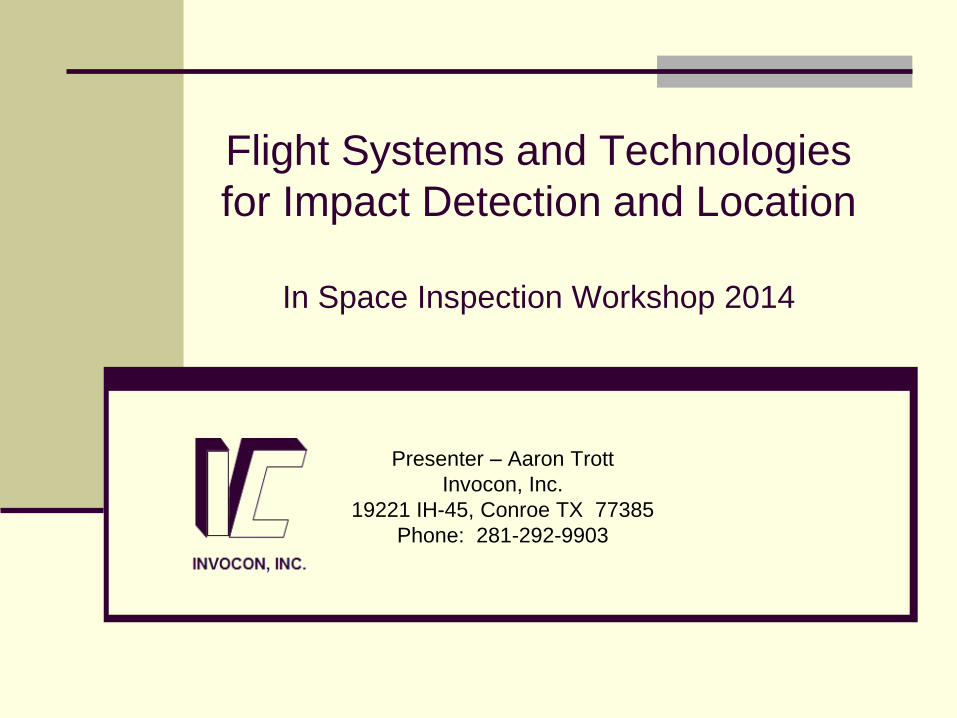
Inspections can be too costly or even impossible
Challenges based on:
Vehicle configuration – can’t get there to inspect it
Vehicle environment – unsafe to inspect
Mission objectives – will interfere with mission
Mission timeline – don’t have time
Mission Cost – fuel, personnel, volume, mass, $$
Considerations:
Must minimize triggering instrumentation or risk mission
objectives – SWaP-C
Triggered events may require re-evaluation of mission
However: If it isn’t broken, don’t meddle with it!
5
Copyright 2014 – Invocon, Inc.
Wing Leading Edge Impact
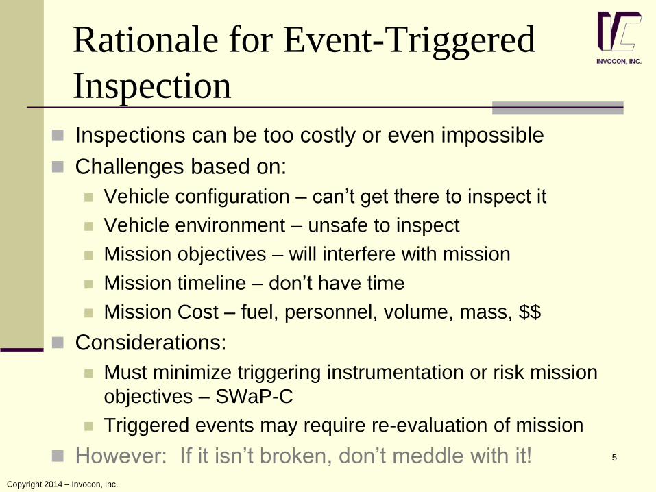
Detection System Shuttle return to flight
In-flight inspection
= primary safety assurance
Impact Detection System
= important to identify
damage
Notify of occurrence
Pinpoint location
Simplified inspections
Used for
Launch to Orbit
MMOD while orbiting 6
Hardware:
44 sensor units , 22 per wing, mounted in 2 locations
Each unit has 3 accelerometer channels & 1 thermal
sensor
132 accelerometers mounted inside wing spare panel
Copyright 2014 – Invocon, Inc.
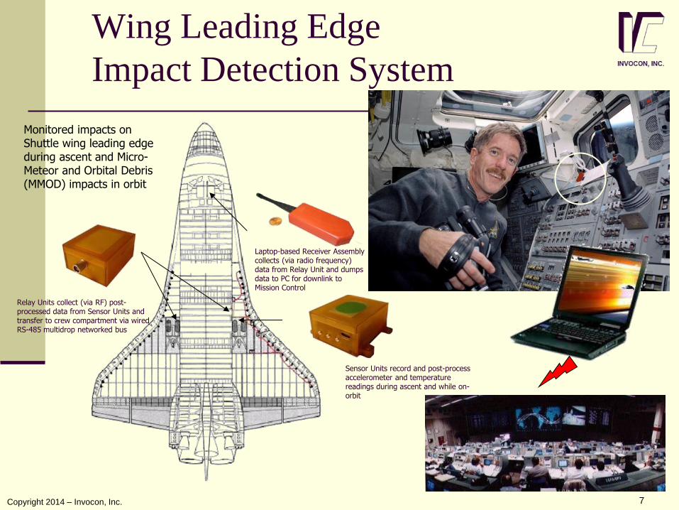
Wing Leading Edge
Impact Detection System
Sensor Units record and post-process accelerometer and temperature readings during ascent and while on-orbit
Relay Units collect (via RF) post-processed data from Sensor Units and transfer to crew compartment via wired RS-485 multidrop networked bus
Laptop-based Receiver Assembly collects (via radio frequency) data from Relay Unit and dumps data to PC for downlink to Mission Control
Monitored impacts on Shuttle wing leading edge during ascent and Micro-Meteor and Orbital Debris (MMOD) impacts in orbit
7 Copyright 2014 – Invocon, Inc.
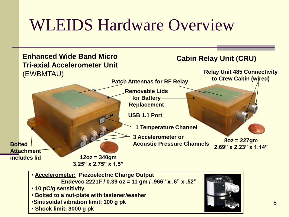
WLEIDS Hardware Overview
3 Accelerometer or
Acoustic Pressure Channels
1 Temperature Channel
USB 1.1 Port
Relay Unit 485 Connectivity
to Crew Cabin (wired) Patch Antennas for RF Relay
Bolted
Attachment
includes lid
Removable Lids
for Battery
Replacement
12oz = 340gm
3.25” x 2.75” x 1.5”
• Accelerometer: Piezoelectric Charge Output
Endevco 2221F / 0.39 oz = 11 gm / .966” x .6” x .52”
• 10 pC/g sensitivity
• Bolted to a nut-plate with fastener/washer
•Sinusoidal vibration limit: 100 g pk
• Shock limit: 3000 g pk
8oz = 227gm
2.69” x 2.23” x 1.14”
Enhanced Wide Band Micro
Tri-axial Accelerometer Unit
(EWBMTAU)
Cabin Relay Unit (CRU)
8

WLEIDS Accelerometer Installation
Accelerometers installed behind WLE spar near the upper/lower attach bolts for RCC Panel assemblies
Panel 10/11 Upper
Panel 10/11 Lower
Panel 9/10 Upper
Panel 9/10 Lower
Thermal Sensor
Centered Behind
Panel 10
Accelerometer
Photographs looking forward inside port wing
9

Sensor Configuration for Ascent Monitoring Cross-strapping for Quadruple Redundancy
Port (OV-103)
Starboard (OV-103)
1027
2 1015
8 7 1
0 9 1
1
1207
1 1019
2
1032
1 1020
2
1024
2 1030
1 1018
2
1022
2 1036
1 1021
1 1025
1 1014
2
1034
2
2 1 4 3 6 5
1028
2 1123
1 1023
1
1108
1 1013
2 1033
2
1
2
13 1
4 1
5 1
6 1
7 1
8 1
9 2
0 2
1
1031
1 Aft
RTD
Fwd
RTD
2
2 Chine Area
1037
8 7 1
0 9 1
1
1044
1 1057
2
1048
1 1053
2
1029
2 1054
1 1008
2
1042
2 1056
1 1026
1
1051
2 1059
1 1060
2
1049
2
2 1 4 3 6 5
1046
2 1040
1 1047
1
1052
1 1041
2 1058
2
1
2
13 1
4 1
5 1
6 1
7 1
8 1
9 2
0 2
1
1043
1 Aft
RTD
Fwd
RTD
2
2 Chine Area
10

Implementation Details
First Flight – Trigger levels
Optimal levels unknown
Set very low to insure that all meaningful events were captured
Flood of data – levels increased for subsequent flights
Compared data with in-flight and ground inspections
11
NASA Photo
INVOCON, INC.
Copyright 2014 – Invocon, Inc.
Expanded operations
Micro-Meteroid and Orbital Debris
(MMOD) Mode
Probability of impact with MMOD is
increasing significantly
Used to monitor vehicle during orbit
Reduce Redundancy – increase time
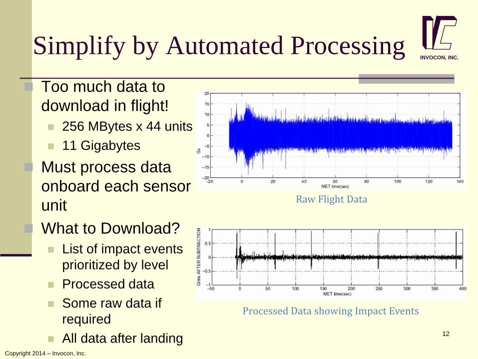
Simplify by Automated Processing
Too much data to
download in flight!
256 MBytes x 44 units
11 Gigabytes
Must process data
onboard each sensor
unit
What to Download?
List of impact events
prioritized by level
Processed data
Some raw data if
required
All data after landing
Raw Flight Data
Processed Data showing Impact Events
12
INVOCON, INC.
Copyright 2014 – Invocon, Inc.
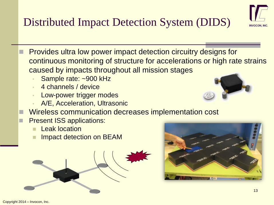
Provides ultra low power impact detection circuitry designs for
continuous monitoring of structure for accelerations or high rate strains
caused by impacts throughout all mission stages • Sample rate: ~900 kHz
• 4 channels / device
• Low-power trigger modes
• A/E, Acceleration, Ultrasonic
Wireless communication decreases implementation cost Present ISS applications:
Leak location
Impact detection on BEAM
Distributed Impact Detection System (DIDS)
13
Copyright 2014 – Invocon, Inc.

Launch Vehicle Instrumentation
The following systems are designed to increase
the capabilities of launch vehicles while
decreasing cost.
Some cost reduction is through simplified
integration
Some of these devices include wireless interfaces.
All of these devices are designed to be used with
wireless telemetry.
These systems are examples of instrumentation
for systems that cannot be inspected due to the
nature of their missions.
14
Copyright 2014 – Invocon, Inc.

Hit Detection/Location Systems
Telemetry Data Acquisition System - TDAS
Measures the response of a grid of up to 256
coaxial wires – 160 ns sampling
Telemeters data to Ground Receiving Units
(GRUs) at 10Mbps
Self contained (power and communication)
Kinetic Impact Position System – KIPS
Low cost version of TDAS
Integrates with vehicle power and
communication
80 ns sampling
15
KIPS
TDAS
Intelligent com link sharing to insure all
important data is transmitted
Have provided impact location for 20+
vehicles Copyright 2014 – Invocon, Inc.

Grid-less transduction technology
replaces or augments wired hit grid
Acoustic and/or RF sensing
Simplifies integration
Installs on vehicle skin
Reduces weight
Provides enhanced situational
awareness
Enables detection of multi-impact
events (i.e., Shrapnel kill weapon)
Grid-less Hit Grid (Patented)
16
Copyright 2014 – Invocon, Inc.

Hypervelocity Impact Damage
Assessment System Phase I SBIR
Expands from detection and location to evaluation
Characterize HVI signals
May have limited time after HVI event to evaluate damage
Much work to be done!
17
Copyright 2014 – Invocon, Inc.
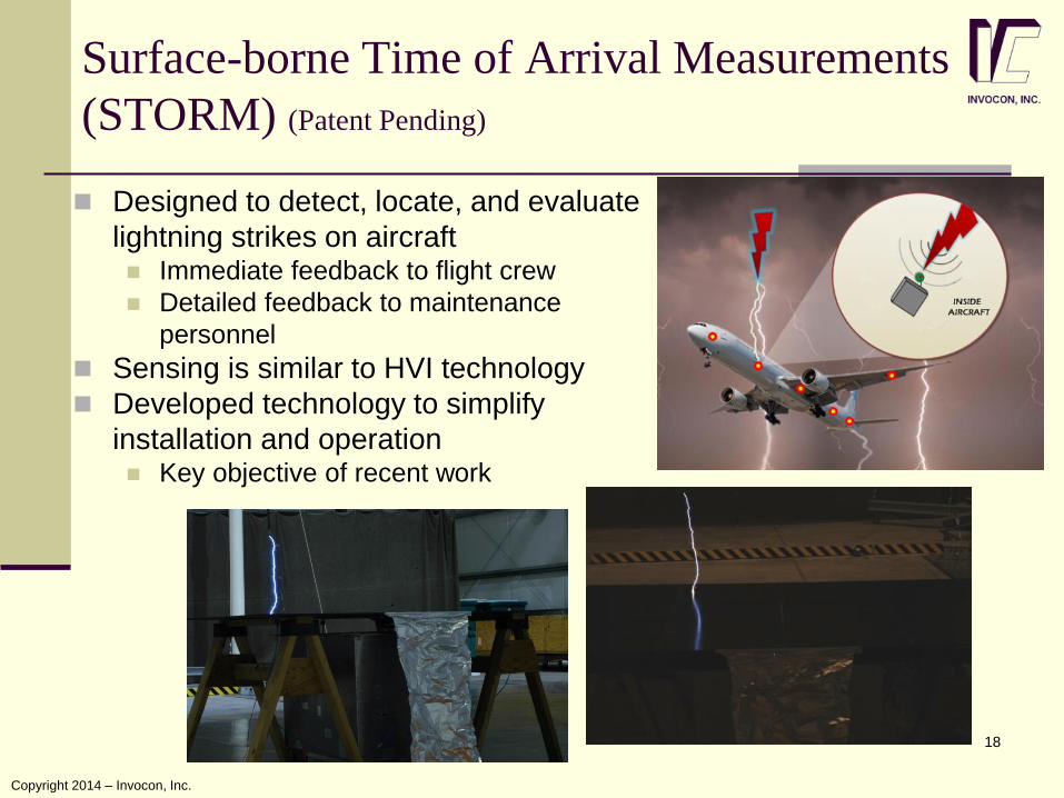
Surface-borne Time of Arrival Measurements
(STORM) (Patent Pending)
18
Designed to detect, locate, and evaluate
lightning strikes on aircraft Immediate feedback to flight crew
Detailed feedback to maintenance
personnel
Sensing is similar to HVI technology
Developed technology to simplify
installation and operation Key objective of recent work
Copyright 2014 – Invocon, Inc.
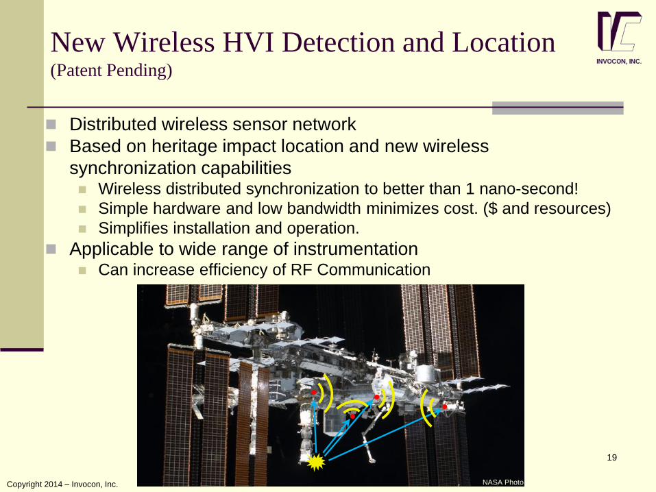
New Wireless HVI Detection and Location (Patent Pending)
19
Distributed wireless sensor network
Based on heritage impact location and new wireless
synchronization capabilities Wireless distributed synchronization to better than 1 nano-second!
Simple hardware and low bandwidth minimizes cost. ($ and resources)
Simplifies installation and operation.
Applicable to wide range of instrumentation Can increase efficiency of RF Communication
NASA Photo Copyright 2014 – Invocon, Inc.

Event-triggered inspections are used by NASA in critical
applications
Impact detection and location are particularly useful in
aerospace applications where structural mass is
minimized
Lower safety margin than other applications
Impacts are a real possibility
Cost-effective (Time and $$$)
Minimizes exposure of structure to potential for
additional damage
Summary
20
Copyright 2014 – Invocon, Inc.
Thanks to my co-workers who have poured significant
energy into developing and refining these capabilities
Thanks to many NASA engineers and scientists for their
cooperation, feedback, and support
Thanks to George Studor for his inputs to this
presentation
Acknowledgments
21