LC Pumps - Universidad De...
5
1168 LCGC NORTH A M E R O VOLUME 26 NUMBER 12 DECEMBER ! 0 0 8 wvrw.chromato graphyon line.cow LC TROUBLESHOOTING After more than 40 years, the reciprocating-piston I pump remains at the heart of the LC system. LC Pumps John W. Dolan LC Troubleshooting Editor H ere we are, more than 40 years after the inicial exploration of high performance liquid chro- matography (HPLC). Many tbings have changed, some innovations have come and gone, but the reciprocating-piston pump still remains as a key component ofthe LC system. We've tried pneumati- cally driven pumps, piston-diaphragm pumps, syringe pumps, and some other ideas, but none have proven to be supe- rior to the reciprocating-piston pump. Yes, some changes have been made, but the basic operation remains the same. This month's "LC Troubleshooting" instalment will take a look at the design of these durable pumps and also exam- ine some ofthe potential weaknesses and how to overcome them. The Basic Design The basic design and operation of the reciprocating-piston pump is illustrated by the single-piston pump shown in Figure 1. The key components are a pis- ton, pump seal, pump head, and a cou- ple of check valves. The piston, usually made of sapphire, is driven back and forth in the pump head by a rotating motor. Various means have been con- ceived to convert the rotary motion of the motor into the bidirectional move- ment ofthe piston. Most commonly, this is done by a cam pressing against one end ofthe piston to push it into the pump head and a spring to push the piston back out. The pump seal is shown in the inset in Figure lc. It is a polymer ring that fits around the piston, and a small lip forms a liquid-tight seal against the piston with the aid of a spring and liquid pressure. A pair of ruby check valves with sapphire seats are mounted on the top and bottom ofthe pump head. The check valves control the direction of flow through the pump. On the intake stroke (Figure la), the piston is withdrawn, which creates a low pressure area inside the pump head. This allows the outlet check valve to ciose and the inlet check valve to open, so that mobile phase flows in to fill the pump head. On tbe delivery stroke (Figure lb). the piston moves into the pump head, and the inlet check valve is closed as the pressure increases. When the pressure inside the pump head exceeds the pressure in the column, the outlet check valve opens and mobile phase flows to the cohimn. When all is working well, this simple pump design is quite reliable. The weak points in the design are the check valves and the pump seal. The operation ofthe check valves and some design improvements were discussed in the June 2008 installment of "LC Trou- bleshooting" (I). Contamination ofthe check valves can cause them to leak, and under the right circumstances, acetoni- trile in the mobile phase can cause the inlet check valve to stick closed. The pump seal forms a seal against the mov- ing piston, and although the sapphire piston is very smooth, the seal eventu- ally will wear out. This wear is acceler- ated if bufFer is allowed to sit in an unused pump, because the liquid behind the seal evaporates and leaves an abrasive layer of buffer crystals. These abrade the seal when the pump is restarted, and can shorten the seal life. Generally the pump seals will last 6-12 months under normal operation if buffers are rinsed from the system before shutdown.
-
Upload
duongthuan -
Category
Documents
-
view
215 -
download
0
Transcript of LC Pumps - Universidad De...

1 1 6 8 LCGC NORTH AMERO VOLUME 26 NUMBER 12 DECEMBER !008 wvrw.chromato graphyon line.cow
LC TROUBLESHOOTING
After more than 40 years,
the reciprocating-piston I
pump remains at the heart
of the LC system.
LC Pumps
John W. DolanLC Troubleshooting Editor
H ere we are, more than 40 yearsafter the inicial exploration ofhigh performance liquid chro-
matography (HPLC). Many tbings havechanged, some innovations have comeand gone, but the reciprocating-pistonpump still remains as a key componentofthe LC system. We've tried pneumati-cally driven pumps, piston-diaphragmpumps, syringe pumps, and some otherideas, but none have proven to be supe-rior to the reciprocating-piston pump.Yes, some changes have been made, butthe basic operation remains the same.This month's "LC Troubleshooting"instalment will take a look at the designof these durable pumps and also exam-ine some ofthe potential weaknessesand how to overcome them.
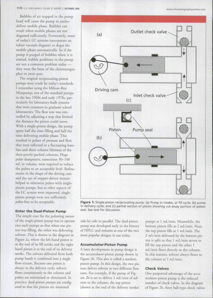
The Basic DesignThe basic design and operation of thereciprocating-piston pump is illustratedby the single-piston pump shown inFigure 1. The key components are a pis-ton, pump seal, pump head, and a cou-ple of check valves. The piston, usuallymade of sapphire, is driven back andforth in the pump head by a rotatingmotor. Various means have been con-ceived to convert the rotary motion ofthe motor into the bidirectional move-ment ofthe piston. Most commonly,this is done by a cam pressing againstone end ofthe piston to push it into thepump head and a spring to push thepiston back out. The pump seal isshown in the inset in Figure lc. It is apolymer ring that fits around the piston,and a small lip forms a liquid-tight sealagainst the piston with the aid of aspring and liquid pressure. A pair ofruby check valves with sapphire seats are
mounted on the top and bottom ofthepump head. The check valves controlthe direction of flow through the pump.On the intake stroke (Figure la), thepiston is withdrawn, which creates a lowpressure area inside the pump head.This allows the outlet check valve tociose and the inlet check valve to open,so that mobile phase flows in to fill thepump head. On tbe delivery stroke(Figure lb). the piston moves into thepump head, and the inlet check valve isclosed as the pressure increases. Whenthe pressure inside the pump headexceeds the pressure in the column, theoutlet check valve opens and mobilephase flows to the cohimn. When all isworking well, this simple pump designis quite reliable.
The weak points in the design are thecheck valves and the pump seal. Theoperation ofthe check valves and somedesign improvements were discussed inthe June 2008 installment of "LC Trou-bleshooting" (I). Contamination ofthecheck valves can cause them to leak, andunder the right circumstances, acetoni-trile in the mobile phase can cause theinlet check valve to stick closed. Thepump seal forms a seal against the mov-ing piston, and although the sapphirepiston is very smooth, the seal eventu-ally will wear out. This wear is acceler-ated if bufFer is allowed to sit in anunused pump, because the liquidbehind the seal evaporates and leaves anabrasive layer of buffer crystals. Theseabrade the seal when the pump isrestarted, and can shorten the seal life.Generally the pump seals will last 6-12months under normal operation ifbuffers are rinsed from the systembefore shutdown.
1 1 7 0 ICGCNORIHAMEfiICA VOLUME 26 NUMB El! 12 DECEMBER ZOOS www. chromarografjhyonline.com
Bubbles of air trapped in the pumphead will cause the pump to under-deliver mobile phase. Bubbles canresult when mobile phases are notdegassed sufficiently. Fortunately, mostof today's LC systems incorporate aninline vacuum degasser to degas themobile phase automatically. So if thepump is purged of bubbles when it isstarted, bubble problems in the pumpare not a common problem today -—they were the bane of the chromatogta-pher in years past.
The original reciproca ci ng-pis tonpumps were crude by today's standards.I remember using the Mllton-RoyMinipump, one of the standard pumpsin the late 1960s and early 1970s, par-ticularly for laboratory-built systemsthat wete common in graduate schoollaboratories. The flow rate was con-trolled by adjusting a stop that limitedthe distance the piston could move.With a single-piston design, the pumpspent half the time filling and half thetime delivering mobile phase. Thisresulted in pulses of pressure and flowthat were reflected in a fluctuating base-line and short column lifetimes of thethen-poorly-packed columns. Hugepulse dampeners, sometimes 50-100mL in volume, were required to reducethe pulses to an acceptable level. Refme-ments in the shape of the driving camand the use of stepper-driven motorshelped to minimize pulses with single-piston pumps, but as other aspects ofthe LC system were improved, single-piston pumps were not sufficientlypulse-free to be acceptable.
Enter the Dual-Piston PumpThe simple cure for the pulsating natureof the single-piston pump was to operatetwo such pumps so that when one pis-ton was filling, the other was deliveringsolvent. This is shown in the dii^ram inFigure 2a, where the left-hand piston isat the end of its fill stroke and the right-hand piston is at the end of its deliverystroke. The solvent delivered from bothpump heads is combined into a singleflow-stream. Because one piston isalways in tbe delivery cycle, solventflows continuously to the column andpulses are minimized or eliminated. Inpractice, dual-piston pumps are config-ured so that the pistons are mounted
(a)Outlet check valve • •
Driving camInlet check valve
t
(b)
Piston Pump seal
3 D
Figure 1: Single-piston reciprocating pump: (a) Pump in intake, or fill cycle; (b) pumpin delivery cycle; and (c) partial section of piston showing cut-away portion of pistonseal. See text for discussion.
side-by-side in parallel. The dtial-pistonpump was developed early in the historyof HPLC and remains as one of tbe twomost popular designs in use today.
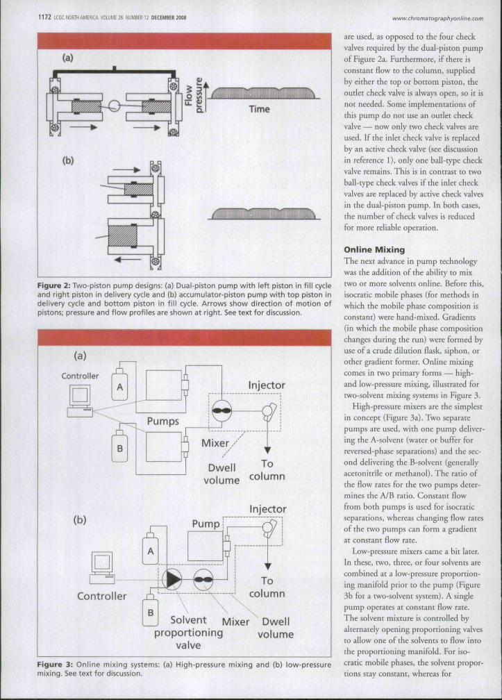
Accumulator-Piston PumpA later development in pump design isthe accumulator-piston pump shown inFigure 2b. This also is called a tandem-piston pump. In this design, the two pis-tons deliver solvent at two different flowrates. For example, if the pump of Fig-ure 2b is set to deliver 1 mL/min of soi-vent Eo the column, the top piston{shown at the end of the delivery stroke)
pumps at 1 mL/min. Meanwhile, thebottom piston fills at 2 mL/min. Next,the top piston fills at 1 mL/min. The2 mL/min delivered by the bottom pis-ton is split so that 1 mL/min serves tofill the top piston and the other 1mL/min flows directly to the coltimn.In this manner, solvent always flows tothe column at 1 mL/min.
Check ValvesOne purported advantage of the accu-mulator-piston pump is the reducednumber of check valves. In the diagramof Figure 2b, three ball-type check valves
1 1 7 2 LCGC NORTH AMERICA VOLUME 26 NUMBER 12 DECEMBER 2008 www. chromatographyonlir\e.corn
(a)
Figure 2: Two-piston pump designs: (a) Dual-piston pump with left piston in fill cycleand right piston in delivery cycle and (b) accumulator-piston pump with top piston indelivery cycle and bottom piston in fill cycle. Arrows show direction of motion ofpistons; pressure and flow profiles are shown at right. See text for discussion.
Dwell To
(b)
volume column
Injector
A
Pump
Controller
BSolvent Mixer Dwell
proportioning volumevalve
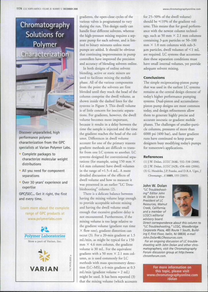
Figure 3: Online mixing systems: (a) High-pressure mixing and (b) low-pressuremixing. See text for discussion.
are used, as opposed to the four checkvalves required by the dual-piston pumpof Figure 2a. Furthermore, if there isconstant flow to the column, supphedby either the top or bottom piston, theoudet check valve is always open, so it isnot needed. Some implementations ofthis pump do not use an outlet checkvalve — now only two check valves areused. If the inlet check valve is replacedby an active check valve (see discussionin reference 1), only one ball-t)'pe checkvalve remains. This is in contrast to twoball-type check valves if the inlet checkvalves are replaced by active check valvesin the dual-piston pump. In both cases,tbe number of check valves is reducedfor more reliable operation.
Online MixingThe next advance in pump technologywas the addition ofthe ability to mixtwo or more solvents online. Before tbis,isocratic mobile phases (for methods inwhich the mobile phase composition isconstant) were hand-mixed. Gradients(in which the mobile phase compositionchanges during the run) were formed byuse of a crude dilution flask, siphon, orother gradient former. Online mixingcomes in two primary forms — high-and low-pressure mixing, illustrated fortwo-solvent mixing systems in Figure 3.
High-pressure mixers are the simplestin concept (Figure 3a). Two separatepumps are used, with one pump deliver-ing the A-solvent (water or bufFer forreversed-phase separations) and the sec-ond delivering tbe B-solvent (generallyacetonitrile or methanol). The ratio ofthe flow rates for the two pumps deter-mines the A/B ratio. Constant flowfrom both pumps is used for isocraticseparations, whereas changing flow ratesofthe two pumps can form a gradientat constant flow rate.
Low-pressure mixers came a bit later.In these, two, three, or four solvents arecombined at a low-pressure proportion-ing manifold prior to the pump (Figure3b for a two-solvent system). A singlepump operates at constant flow rate.The solvent mixture is controlled byalternately opening proportioning valvesto allow one of the solvents to flow intothe proportioning manifold. For iso-cratic mobile phase.s, the solvent propor-tions stay constant, whereas for
1 1 7 4 LCGC NORTH AMERICA VOLUME 26 NUMBEfl 12 DECEMBER 2008 www. chrorna tographyonlin e.com
ChromatographySolutions for
Polymerterizatio;.
Discover utiparalleled, highperformance polymercharacterization from the GPCspecialists at Varian Polymer Labs.
Complete packages tocharacterize molecular weightdistributions
All you need for componentseparations
Over 30 years' experience andexpertise
GPC/SEC... Get it right, the firstand every time.
more about the complete
range of GPC products at
www.polymertabs.com
Polymer LaboratoñesNow a part of Varian, Inc.
VARIAN
gradients, the open-close cycles of thevarious valves is programmed to varyduring the run. This design easily canhandle four different solvents, whereasthe high-pressure mixing requires a sep-arate pump for each solvent, and is lim-ited to binary mixtures unless morepumps are added. It should he obviousthat continuing improvements m pumpcontrollers have improved the precisionand accuracy of blending solvents online.
In both designs of online solventblending, active or static mbcets areused to facilitate mixing the mobilephase. All of the various componentsfrom the point the solvents ate firstblended until they reach the head of thecolumn comprise the dwell volume, asshown inside the dashed lines for thesystems in Figure 3. This dwell volumeis of little concern for ¡socratic separa-tions. For gradients, however, the dwellvolume becomes more important,because it results in a delay between thetime the sample is injected and the timethe gradient reaches the head of the col-umn. Difl'erences in dwell volumeaccount for one of the primary reasonsgradient methods are difHcult to trans-fer from one LC system to another. LCsystems designed for conventional sepa-rations (for example, using 150 mm X4.6 mm columns) have dwell volumesin the range of = 1.5-4 mL. A moredetailed discussion of the effects ofdwell volume and how to measure itwas presented in an earlier "LC Trou-bleshooting" column (2).
There is a delicate balance betweenhaving the mixing volume large enoughto provide acceptable solvent mixingand having tbe dwell volume smallenough that excessive gradient delay isnot encountered. Furthermore, ¡f themixing volume is too large relative tothe gradient volume (gradient run timeX flow rate), gradient distortion canoccur (3). For a 20-min gradient at 1.5mL/min, as might be typical for a 150mm X 4.6 mm column, the gradientvolume is 30 mL. Fot the equivalentgradient with a 50 mm X 2.1 mm col-umn, as is used commonly for LCmethods with mass spectrometry detec-tion (LC-MS), a 6-min gradient at 0.3mL/min (gradient volume = 2 mL)might be used. It has been teported (3)that the mixing volume (which accounts
for 25-50% of the dwell volume)should be ^ 10% of the gradient vol-ume. This means that for good perform-ance with the newest column technol-ogy, such as 50 mm X 2.1 mm columnscontaining 3-M.m particles or 50-100mm X LO mm columns with sub-3-\Lm particles, dwell volumes of <1 mLare required. LC systems that accommo-date these separation conditions mtisthave small internal volumes, yet provideadequate solvent mixing.
ConclusionsThe simple reciprocating-piston pumpthat was used in the earliest LC systemsremains as the central design element oftoday's higher performance pumpingsystems. Dual-piston and accumulator-piston pump designs are most commontoday, and design refmements allowthem to generate highly precise andaccurate isocratic or gradient mobilephases. The challenges of smaller-parti-cle columns, pressures of more than6000 psi (400 bar), and faster gradientruns have continued to keep pumpdesigners busy modifying today's pumpsfor tomorrow's applications.
References{]) J.W. Dolan, ¿CGC26(6), 532-538 (2008).
(2) J.W. Dolan. ¿CGC24(5), 458^66 (2006),
(3) G. Hendriks, J.P. Franke, and D.R.A. Ugcs,/.
Chromatogr.. A 1089, 193 (2005).
John W. Dolan"LC Troubleshoot-ing" Editor JohnW. Dolar) is Vice-President of LCResources, WalnutCreek, California;and a member ofLCGC's editorialadvisory board.
Direct correspondence about this column to"LC Troubleshooting, " LCGC, WoodbridgeCorporate Plaza, 485 Route I South, Build-ing F, First Floor, Iselin. NJ 08830, e-maiiJohn.Dolan'SLCResources.com.
For an ongoing discussion of LC trouble-shooting with John Dolan and other chro-matographers, visit the ChromatographyForum discussion group at http.llwww.chromforum.com.
For more Information onthis topic, please visit
wwvtf.chromatographyonline.com/dolan


![Review Overview of the applications of liquid ...quimica.udea.edu.co/~carlopez/cromatohplc/review_hplc_ms_foods.pdfgiving positive identification of components of ... [29–31] mass](https://static.fdocuments.in/doc/165x107/5adb8ac87f8b9aee348e2d80/review-overview-of-the-applications-of-liquid-carlopezcromatohplcreviewhplcmsfoodspdfgiving.jpg)