LBC, D-series - SKF.com on the specific bearing size, the LBC, D-series linear ball bearings can...
32
LBC, D-series Next generation of SKF linear ball bearings and units • Increased level of performance • Improved lifetime • Improved reliability and robustness • Easier to mount
Transcript of LBC, D-series - SKF.com on the specific bearing size, the LBC, D-series linear ball bearings can...

LBC, D-series Next generation of SKF linear ball bearings and units
• Increased level of performance
• Improved lifetime
• Improved reliability and robustness
• Easier to mount

2

Content
SKF – the knowledge engineering company . . . . . . . . . . . . . . . 4
LBC, D-series – next generation of linear ball bearings
and units . . . . . . . . . . . . . . . . . . . . . . . . . . . . . . . . . . . . . . . . . . . 6
Applications . . . . . . . . . . . . . . . . . . . . . . . . . . . . . . . . . . . . . . . 7
Features and benefits . . . . . . . . . . . . . . . . . . . . . . . . . . . . . . . . . 8
Technical and calculation data. . . . . . . . . . . . . . . . . . . . . . . . . 10
Permissible operating conditions . . . . . . . . . . . . . . . . . . . . . . 10
Friction . . . . . . . . . . . . . . . . . . . . . . . . . . . . . . . . . . . . . . . . . . 10
Calculation bases and factors of influence . . . . . . . . . . . . . . . . 10
Operating conditions. . . . . . . . . . . . . . . . . . . . . . . . . . . . . . . . 12
Impact of stroke length, factor fs . . . . . . . . . . . . . . . . . . . . . . . 13
Number of loaded bearings per shaft, factor fi . . . . . . . . . . . . 13
Influence of load direction, factors fl and fl0 . . . . . . . . . . . . . . . 13
Mounting and maintenance . . . . . . . . . . . . . . . . . . . . . . . . . . 13
Product overview . . . . . . . . . . . . . . . . . . . . . . . . . . . . . . . . . . . . 14
Product tables . . . . . . . . . . . . . . . . . . . . . . . . . . . . . . . . . . . . . 15
Linear ball bearings ISO series 3 . . . . . . . . . . . . . . . . . . . . . . . . 15
Linear ball bearings – LBCR .. D . . . . . . . . . . . . . . . . . . . . . . . 15
Linear ball bearings – LBCD .. D . . . . . . . . . . . . . . . . . . . . . . . 15
Axial and rotational fixation – LBC, D-series . . . . . . . . . . . . . . 16
Grease fittings – for LBC, D-series . . . . . . . . . . . . . . . . . . . . . 17
Linear bearing units, ISO series 3 . . . . . . . . . . . . . . . . . . . . . . . . 18
Linear bearing units – LUCD .. D . . . . . . . . . . . . . . . . . . . . . . . 19
Linear bearing units – LUCE .. D . . . . . . . . . . . . . . . . . . . . . . . 20
Linear bearing units – LUND .. D . . . . . . . . . . . . . . . . . . . . . . 21
Linear bearing units – LUNE .. D . . . . . . . . . . . . . . . . . . . . . . . 22
Flanged linear bearing units – LVCR .. D . . . . . . . . . . . . . . . . . 23
Tandem linear bearing units – LTCD .. D . . . . . . . . . . . . . . . . . 24
Quadro linear bearing units – LQCD .. D . . . . . . . . . . . . . . . . . 25
Specification sheet – Linear Ball bearing . . . . . . . . . . . . . . . . 27
3

From one simple but
inspired solution to
a misalignment
problem in a textile
mill in Sweden, and
fifteen employees in
1907, SKF has
grown to become a
global industrial
knowledge leader.
Over the years we have built on our exper-
tise in bearings, extending it to seals, me-
chatronics, services and lubrication systems.
Our knowledge network includes 46 000
employees, 15 000 distributor partners,
offices in more than 130 countries, and a
growing number of SKF Solution Factory
sites around the world.
Research and development
We have hands-on experience in over forty
industries, based on our employees’ know-
ledge of real life conditions. In addition our
world-leading experts and university part-
ners who pioneer advanced theoretical
research and development in areas includ-
ing tribology, condition monitoring, asset
management and bearing life theory. Our
ongoing commitment to research and
devel opment helps us keep our customers
at the forefront of their industries.
Meeting the toughest challenges
Our network of knowledge and experience
along with our understanding of how our
core technologies can be combined helps
us create innovative solutions that meet the
toughest of challenges. We work closely with
our customers throughout the asset life
cycle, helping them to profitably and
re spon sibly grow their businesses.
SKF Solution Factory makes SKF knowledge and manu facturing expertise available locally, to provide unique solutions and services to our customers.
Working with SKF IT and logistics systems and application experts, SKF Authorized Distributors deliver a valuable mix of product and application knowledge to customers worldwide.
Working for a sustainable future
Since 2005, SKF has worked to reduce the
negative environmental impact from our
own operations and those of our suppliers.
Our continuing technology development
intro duced the SKF BeyondZero portfolio
of products and services which improve
efficiency and reduce energy losses, as well
as enable new technol ogies harnessing
wind, solar and ocean power. This combined
approach helps reduce the environmental
impact both in our own oper ations and in
our customers’.
SKF – the knowledge engineering company
BearingsSKF is the world leader in the design, development and manufacture of high performance rolling bearings, plain bearings, bearing units and housings.
Machinery maintenanceCondition monitoring technologies and main-tenance services from SKF can help minimize unplanned downtime, improve operational efficiency and reduce maintenance costs.
Sealing solutionsSKF offers standard seals and custom engineered sealing solutions to increase uptime, improve machine reliability, reduce friction and power losses, and extend lubricant life.
MechatronicsSKF fly-by-wire systems for aircraft and drive-by-wire systems for off-road, agricultural and forklift applications replace heavy, grease or oil consuming mechanical and hydraulic systems.
Lubrication solutionsFrom specialized lubricants to state-of-the-art lubrication systems and lubrication management ser vices, lubrication solutions from SKF can help to reduce lubrication related downtime and lubricant consumption.
Actuation and motion controlWith a wide assortment of products – from actu-ators and ball screws to profile rail guides – SKF can work with you to solve your most pressing linear system challenges.
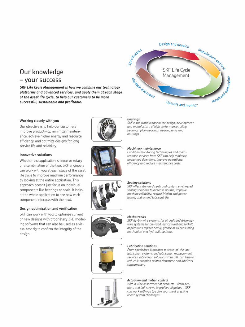
Our knowledge – your successSKF Life Cycle Management is how we combine our technology
platforms and advanced ser vices, and apply them at each stage
of the asset life cycle, to help our customers to be more
success ful, sustainable and profitable.
Working closely with you
Our objective is to help our customers
improve productivity, minimize main ten-
ance, achieve higher energy and resource
efficiency, and optimize designs for long
service life and reliability.
Innovative solutions
Whether the application is linear or rotary
or a combination of the two, SKF engineers
can work with you at each stage of the asset
life cycle to improve machine performance
by looking at the entire application. This
approach doesn’t just focus on individual
components like bearings or seals. It looks
at the whole application to see how each
com po nent interacts with the next.
Design optimization and verification
SKF can work with you to optimize current
or new designs with proprietary 3-D model-
ing software that can also be used as a vir-
tual test rig to confirm the integrity of the
design.
SKF Life Cycle Management
Design and developManufacture and test
Spec
ifica
tion
Install a
nd com
mis
sion
Operate and monitor
Maintain and repair

LBC, D-series Next generation of SKF linear ball bearings and units
LBC, D-series is the latest range of SKF linear
ball bearings, improving on the current SKF
range of linear ball bearings already recog-
nized as best in class throughout industry.
LBC, D-series linear ball bearings consist
of a cage and raceway segments to support
ball sets and seals. The raceways with an
exceptionally long track and a precision ma-
chined profile accommodate heavy loads.
LBC, D-series linear ball bearings are avail-
able for shaft diameters 12 to 40 mm, with
the choice of double lip seals. Bearings with
stainless steel balls and raceways are avail-
able for contaminated environments. They
can be used in combination with SKF stain-
less steel shafts for a corrosion resistant
guidance system.
If required, a self-aligning version of the
LBC, D-series is available. This LBCD .. D
bearing accommodates tilting of the whole
bearing through an angle up to ±30 minutes
of arc. The tilting feature compensates for
misalignment which may be caused by sig-
nificant bending of an unsupported shaft or
by misalignment due to manufacturing and
fitting tolerances of the adjacent construc-
tion. The cage and seals have been opti-
mized to accommodate the self-aligning
capability so that the bearing and especially
the shields or seals remain concentric with
the shaft.
Pos. Component Material1 Cage PA2 Recirculation cap PA3 Double lip seal PU4 Balls Bearing steel5 Raceways Steel6 Lubrication port –
5
1
2
4
3
6
6

Applications
Automation machineryAutomation processes are often based on
linear ball bearing slides. These enable the
insertion, exact positioning and removal of
work pieces.
Customer benefits
• High running accuracy
• Can be used in harsh / polluted
environment
• High speed
• Efficient sealing provides long
service life
Pick and place machinesMachines performing pick and place tasks,
robots in laboratories or automated handling
machines, can be equipped with linear ball
bearings.
Customer benefits
• High running accuracy
• Can be used in clean environment
• High speed
Filling machinesThe fillers move up and down to fill bottles
that slide down the production line. The ver-
tical movement is supported by linear ball
bearings.
Customer benefits
• Special grease enables usage with food
(optional)
• Pre-lubrication and double lip seals
provide long lifetime
• Long service time
Platform screen doorsThe door systems contain linear ball bear-
ings, which guide the parallel movement of
the door to the side of the vehicle.
Customer benefits
• Low maintenance and long service
intervals
• Smooth running performance enables
easy door movement
• Bearings are sealed from contamination
by double-lip seals
It is strongly recommended that the application of bearings proposed by SKF are tested in operational conditions as close as possible to real ones. Please contact SKF in case of any further questions.
7

F eatures and benefits
Improved load ratings and lifetimeDepending on the specific bearing size, the LBC, D-series linear ball bearings can deliver up to 15% higher dynamic load carrying capacity and up to 50% longer bearing lifetime than previous LBC designs. Optimized ball tracks and larger rolling elements enable the performance increases and consequently, greater reliability and productivity for the application. Higher load carrying capacity also gives product designers and manufacturers the flexibility to downsize designs or to increase loading.
Full ISO interchangeabilityLBC, D-series linear ball bearings are manufactured according to ISO 10285 dimensions and tolerances, making them fully inter changeable with previous LBC or ISO Series 3 bearings. For product designers and manufacturers, the new LBC, D-series bearings offer a flexible, drop-in replacement option for existing equipment designs.
Self-aligning capabilityThe LBC, D-series linear ball bearings include the self-aligning LBCD .. D variant. Self-aligning LBCD .. D linear ball bearings can accommodate tilting of the whole bearing through an angle of ±30 minutes of arc. This tilting fea-ture compensates for misalignments caused by fitting or manufacturing tol-erances of the adjacent construction, or by significant bending of an unsup-ported shaft. The LBCD .. D bearing cage, seals and shields have been optimized to accommodate the self-aligning feature so that the bearing, shields and seals remain concentric with the shaft. LBCD .. D bearings ensure good running characteristics despite misalignment, ultimately resulting in in-creased bearing lifetime and reduced maintenance demands.
H
L
A
L
A
Fw
Fw
Recommended main load direction
Steelball
Cage
Load zone
Returning zone
Raceway
8

Factory pre-lubricationAll LBC, D-series bearings and units are factory-lubricated with the optimum amount of SKF LGEP2 grease. Pre-lubrication means LBC, D-series bearings arrive “shaft ready” to help reduce assembly times and mounting mistakes, while no lubrication requirements after mounting helps to cut cost. Food compatible grease and other greases are available on request.
Easier mountingTo help make bearing mounting procedures more ergonomic, LBC, D-series bearings feature two indicator marks on the front side: one for main load di-rection, one for lubrication port position. The indicators enable fast bearing orientation in the housing, reducing the risk of errors as well as bearing mounting times.
Optimized cage designLBC, D-series bearings have an optimized cage design with few components than with previous designs; a reduction that increases the reliability of the bearing and the application. The new cage design features larger ball sizes, ball tracks, grease reservoir and recirculation channels. This combination of features helps ensure smooth operation with less friction and noise, making LBC, D-series bearings a good option even for sensitive applications such as the medical industry.
Integrated and design-optimized raceway
Double lip seals in heavy-duty elastomer
Engraved date code on the cage for traceability
Optimized ball recirculation
Indicator for lubrication port position
Indicator for the main load direction
9

Technical and calculation data
Permissible operating conditions
The correct functioning of a linear ball bear-
ing guidance system can only be maintained
if the principal operating limits are not ex-
ceeded. The validity of the operating life cal-
culations depends on the observance of the
operating conditions described below.
Dynamic values
LBC, D-series linear ball bearings can reach
a maximum speed of vmax = 5 m/s.
The maximum permissible acceleration is
amax = 100 m/s2.
Permissible operating temperature
The permissible operating temperature
range for continuous operation of SKF linear
ball bearings is from –20 to +80 °C and is
determined by the cage and seal materials.
Lower and higher temperatures can be tol-
erated for brief periods.
Friction
Friction in a linear guidance system is affect-
ed, apart from the loading, by a number of
other factors, notably the type and size of
the bearing, the operating speed, as well as
the quality and the quantity of lubricant
used († table 1).
Calculation bases and factors of influence
Static safety factor
The static safety factor is expressed as the
relationship between the static load rating
and the maximum static bearing load.
The static safety factor indicates the level
of safety against permanent plastic defor-
mation of the steel balls, raceways and
guide shaft and is calculated according to
formulae 1 and 2.
Fmax
[1] P0 = ———— fm flo fh0
C0
[2] s0 = —
P0
where
C0 = basic static load rating [N]
fm = factor for misalignment1)
fl0 = factor for direction of load
fh0 = factor for surface hardness of shaft1)
Fmax = maximum external static load [N]
P0 = maximum static load [N]
s0 = static safety factor
Depending on the operating conditions and
requirements on the quietness on running,
a static safety factor so according to table 2
is recommended based on experience.
Table 1
Sliding and starting friction values for lubricated LBCR and LBCD, D-series linear ball bearings with two seals.
Bearing size Friction forcesRunning Starting
– N N
12 2,5 516 3 720 4 8
25 5 1130 7 1440 8 19
Table 4
Factor fs depending on the ratio ls/lt
ls/lt fs
1,0 1,000,9 0,910,8 0,82
0,7 0,730,6 0,630,5 0,54
0,4 0,440,3 0,340,2 0,23
0,1 0,13
Table 3
Raceway length lt of the different linear ball bearing sizes
Type lt
LBC. 12 D 18,4LBC. 16 D 21,2LBC. 20 D 27,6
LBC. 25 D 37,2LBC. 30 D 45,4LBC. 40 D 50,8
Table 2
Recommended static safety (minimum values)
Operating conditionss0
from up to
Smooth vibration free 1 2
Normal running 2 4
Shock loads or vibration 3 5
10

Modified basic rating life
If the load situation is known and the factors
have been determined, then the equivalent
dynamic load and modified basic rating life
can be calculated according to the following
formulae.
F
[3] P = ————–
fm fl fh fi
q C w3
[4] Lns = 100 c1 c2 fs — < P z
where
Lns = modified basic rating life [km]
c1 = factor for reliability
c2 = factor for operating conditions
fs = factor for stroke length
fm = factor for misalignment1)
fl = factor for direction of load
fh = factor for surface hardness of shaft1)
fi = factor for the number of loaded
bearings per shaft
C = dynamic load rating [N]
F = external bearing load [N]
P = equivalent dynamic load
Req uisite reliability Factor c1 is used for lifetime calculations
where a reliability higher than 90% is
needed. The corresponding values can be
found in († table 5).
Table 5
Factor c1 for reliability
Reliability Lns c1
%
90 L10s 195 L5s 0,6296 L4s 0,5397 L3s 0,4498 L2s 0,3399 L1s 0,21
1) These factors, including an explanation as well as detailed calculation examples, can be found in the SKF technical handbook, publication 6402.
11

Operating conditionsThe lubrication effectiveness is strongly
dependent on the degree of separation
between the steel balls and raceway surfaces
in the contact zones. A specific minimum
viscosity is required for the formation of an
effectively separating lubricating film at op-
erating temperature, taking into account the
kinematic conditions. Assuming a normal
level of cleanliness of the guide shaft as well
as effective sealing, factor c2 depends on the
viscosity ratio k exclusively. k designates the
ratio between the actual kinematic viscosity
and the requisite minimum viscosity
(† formula 5)
n
[5] k = —–
n1
Diagram 2
Determining factor c2 for operating conditions
0,1 0,3 0,5 0,7 0,9 1,1
1,2
1,0
0,8
0,6
0,4
0,2
0,0
c2
k = n/n1
where
k = viscosity ratio
n = actual kinematic viscosity [mm2/s]
n1 = requisite minimum viscosity [mm2/s]
The requisite minimum viscosity n1 for
LBCR … D linear bearings depends on the
mean speed († diagram 1)
The value for n1 can be related to the actual
viscosity n according to formula [5] in order
to obtain k. Now c2 can be taken from the
adjacent diagram († diagram 2). If the
viscosity ratio k is less than 1, a lubricant
with EP additives is recommended. If
lubricants with EP additives are used, the
higher value for c2 can be used for
calculation.
Diagram 1
Requisite kinematic viscosity n1
3 4 5 6 7 8 10 14 20 25 30 40 50 60 80 10020
50
100
200
500
1 000
2 000
5 000
10 000
n1 [mm2/s]
Fw [mm]
v = 1 m/s
3
5
10
0,1
0,050,03
12

Table 6
Factor fl for number of loaded bearings per shaft
Number of bearings If c ≥ 1,5 lt If c < 1,5 lt fi fi
1 1 12 1 0,813 1 0,72
lt
c
350340
330320
310
300
290
280
270
260
250
240
230
220210
200190180170
160150
140
130
120
110
100
90
80
fl0
fl
70
60
50
4030
20 10
F
01,00,90,80,70,60,50,40,30,20,1
Diagram 3
Factors fl and flO related to the direction of load for LBCR and LBCD linear ball bearings
Impact of stroke length, factor fs
Strokes shorter than the raceway length of
the linear ball bearing († table 3, page 10)
have a negative influence on the achievable
life of a guidance system. Based on the ratio
of the single stroke length ls relative to race-
way length lt, factor fs is determined accord-
ing to table 4, page 10.
Number of loaded bearings per shaft, factor fi
Most linear ball bearing configurations fea-
ture two (or more) bearings mounted on
one shaft. The load distribution on these
various bearings is strongly influenced by
the mounting accuracy, the manufacturing
quality of the adjacent components, and in
particular, the distance between the bear-
ings. Factor fi takes these influences on
bearing loading into account based on the
number of bearings per shaft and the dis-
tance between them († table 6).
Note
This factor has no influence when the bear-
ings are mounted in the same accurate drill-
ing as used in the original housings from SKF.
Influence of load direction, factors fl and fl0
Linear ball bearings and units of the LBCR
and LBCD, D-series design must be mounted
so that the line of action of the load falls
within the main load direction which is
marked on the end of the cage, see Cmax
and C0 max values in the data table (†
Easier mounting, page 9).
If the direction of the load deviates from
the optimum, the load ratings must be
corrected using the factors fl and fl0 (†
diagram 3).
In case the load direction is unknown the
C min and C0 min values shown in the data
table do apply.
Mounting and maintenanceMounting instructions as well as methods
for the required axial fixation for the LBC, D-
series bearings can be found in the SKF
technical handbook, publication 6402.
This publication also includes maintenance
instructions.
13
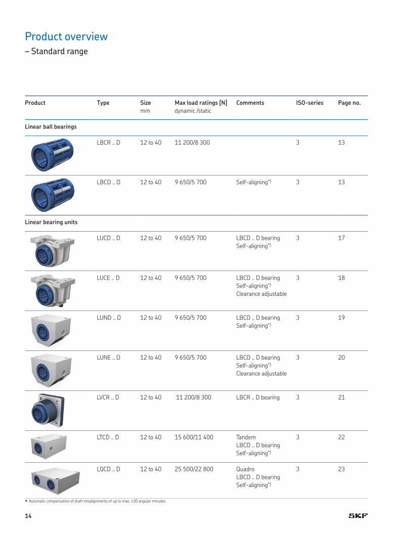
Product overview
– Standard range
* A u t o ma tic compensation of shaft misalignments of up to max. ±30 angular minutes.
Product Type Size
mm
Max load ratings [N]
dy n a mic /static
Comments ISO-series Page no.
Linear ball bearings
LBCR .. D 12 to 40 11 200/8 300 3 13
LBCD .. D 12 to 40 9 650/5 700 Self-aligning*) 3 13
Linear bearing units
LUCD .. D 12 to 40 9 650/5 700 LBCD .. D bearing
Self-aligning*)
3 17
LUCE .. D 12 to 40 9 650/5 700 LBCD .. D bearing
Self-aligning*)
Clearance adjustable
3 18
LUND .. D 12 to 40 9 650/5 700 LBCD .. D bearing
Self-aligning*)
3 19
LUNE .. D 12 to 40 9 650/5 700 LBCD .. D bearing
Self-aligning*)
Clearance adjustable
3 20
LVCR .. D 12 to 40 11 200/8 300 LBCR .. D bearing 3 21
LTCD .. D 12 to 40 15 600/11 400 Tandem
LBCD .. D bearing
Self-aligning*)
3 22
LQCD .. D 12 to 40 25 500/22 800 Quadro
LBCD .. D bearing
Self-aligning*)
3 23
14

F W
C
b b
D
C 1F
FW
C
b b
D
C1
30'30'
F
12 22 32 22,6 1,3 5 930 1 370 695 1 120 0,02 LBCR 12 D LBCR 12 D-2LS16 26 36 24,6 1,3 5 1 080 1 600 800 1 290 0,026 LBCR 16 D LBCR 16 D-2LS20 32 45 31,2 1,6 6 2 200 3 250 1 630 2 650 0,056 LBCR 20 D LBCR 20 D-2LS
25 40 58 43,7 1,85 6 3 100 4 550 2 360 3 800 0,108 LBCR 25 D LBCR 25 D-2LS30 47 68 51,7 1,85 6 4 800 7 100 3 550 5 700 0,122 LBCR 30 D LBCR 30 D-2LS40 62 80 60,3 2,15 6 7 650 11 200 5 100 8 300 0,205 LBCR 40 D LBCR 40 D-2LS
12 22 32 22,6 1,3 5 800 1 220 570 930 0,02 LBCD 12 D LBCD 12 D-2LS16 26 36 24,6 1,3 5 950 1 400 655 1 060 0,025 LBCD 16 D LBCD 16 D-2LS20 32 45 31,2 1,6 6 1 730 2 550 1 120 1 800 0,055 LBCD 20 D LBCD 20 D-2LS
25 40 58 43,7 1,85 6 2 600 3 800 1 430 2 320 0,106 LBCD 25 D LBCD 25 D-2LS30 47 68 51,7 1,85 6 3 800 5 600 2 320 3 750 0,120 LBCD 30 D LBCD 30 D-2LS40 62 80 60,3 2,15 6 6 550 9 650 3 350 5 700 0,200 LBCD 40 D LBCD 40 D-2LS
Dimensions No. of ball rows
Basic load ratings Mass Designationsdynamic static Linear ball bearing
without seals with 2 double lip sealsFw D C C1 b C C0
min max min max
mm N kg –
Dimensions No. of ball rows
Basic load ratings Mass Designationsdynamic static Linear ball bearing
without seals with 2 double lip sealsFw D C C1 b C C0
min max min max
mm N kg –
Linear ball bearings – LBCR .. D
Closed design
Fw 12 – 40 mm
Linear ball bearings – LBCD .. D
Self-aligning closed design
Fw 12 – 40 mm
1) Direction for max. load ratingsUpon request, these bearings are available in stainless steel version, identified by a HV6 suffix in the designation, e.g. LBCR 20 D-2LS/HV6Linear ball bearings are available with double lip seal on one side only (seal located on the right side of the bearing - marked with the SKF logo on the cage). Designation example: LBCR 20 D-LS
1) Direction for max. load ratingsUpon request, these bearings are available in stainless steel version, identified by a HV6 suffix in the designation, e.g. LBCD 20 D-2LS/HV6Linear ball bearings are available with double lip seal on one side only (seal located on the right side of the bearing - marked with the SKF logo on the cage). Designation example: LBCD 20 D-LS
With 2 double lip seals
With 2 double lip seals
Without seals
Without seals
1)
1)
15

Axial and rotational fixation – LBC, D series
C losed design
Fw 12 – 40 mm
K 1
Fw
K1
K2
s
Fw
K1
K2
s
Fw
= =
t1
t1 t1
t2t2
12 3,0 2,6 – – – 2 VN-LHC 20 M 4 316 3,0 2,6 – – – 2 VN-LHC 20 M 4 320 3,0 2,6 – – – 2 VN-LHC 20 M 4 3
25 3,5 4,5 3,0 1,4 1,5 3 VN-LHC 40 M 5 3,5 / 330 3,5 4,5 3,0 2,3 2 4 VN-LHC 40 M 5 3,5 / 340 3,5 4,5 3,0 2,7 1,5 4 VN-LHC 40 M 5 3,5 / 3
Dimensions Design Appropriate Grub Pins3)
grease fittings1) screws2) Diameter
Fw K14) t1 K2
5) t2 s
mm – – mm
1) Recommendations for holes to take grease fittings: † page 152) Grub screws according to DIN EN 27435 or DIN EN ISO 4028.3) Straight pins according to DIN EN ISO 2338, slotted pins - DIN EN ISO 8752 or grooved pins - DIN EN ISO 8739 and DIN EN ISO 8744.4) For relubrication as well as location of linear bearing in SKF housings.5) Alternative bore hole for location in specific housings from other manufacturers.
Design3 Design 4
Design 2
16
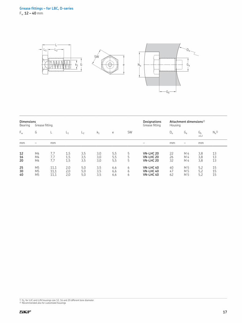
Grease fittings – for LBC, D-series
Fw 12 – 40 mm
L
N a
D a
G e
S W
L2L1
k1 Ga
Gb
12 M4 7,7 1,5 3,5 3,0 5,5 5 VN-LHC 20 22 M 4 3,8 1316 M4 7,7 1,5 3,5 3,0 5,5 5 VN-LHC 20 26 M 4 3,8 1320 M4 7,7 1,5 3,5 3,0 5,5 5 VN-LHC 20 32 M 4 3,8 13
25 M5 11,1 2,0 5,0 3,5 6,6 6 VN-LHC 40 40 M 5 5,2 1530 M5 11,1 2,0 5,0 3,5 6,6 6 VN-LHC 40 47 M 5 5,2 1540 M5 11,1 2,0 5,0 3,5 6,6 6 VN-LHC 40 62 M 5 5,2 15
Dimensions Designations Attachment dimensions2)
Bearing Grease fitting Grease fitting Housing
Fw G L L1 L2 k1 e SW Da Ga Gb Na1)
? 0,2
mm – mm – mm – mm
1) Na: for LUC and LUN housings size 12, 16 and 20 different bore diameter.2) Recommended also for customized housings
17

Linear bearing units, ISO series 3
A comprehensive range of linear ball bearing
units are available. In addition to the basic
design - a housing containing a single bear-
ing, there are also flanged units as well as
tandem and quadro units available.
Linear bearing units consist of a light-
weight, cast aluminium housing that has
been optimized to provide high strength and
stiffness. Due to their light weight, accelera-
tion and inertia forces are kept to a min-
imum. LUC .. D linear bearing units are
available for shaft diameters ranging from
12 to 40 mm.
LUCD .. D
LUCD .. D linear bearing units offer a simple
means of creating an economical linear
guidance system. LUCD .. D linear bearing
units (for shaft diameters ranging from 12
to 40 mm) are normally supplied with a
self-aligning LBCD .. D shielded or optional
sealed linear ball bearing. A grease fitting
serves to retain the bearing axially and pre-
vent it from turning.
LUCE .. D
LUCE .. D linear bearing units are similar in
design to the LUCD .. D units but instead of
a closed housing, these units have a open
housing with an adjustment screw. These
units are typically used for arrangements
requiring zero clearance or preload.
LUND .. D LUNE .. D
LUN .. D linear bearing units are supplied as
standard with shielded or sealed self-align-
ing linear ball bearings. Two versions are
available: closed (LUND .. D) and adjustable
(LUNE .. D).
In contrast to the LUC .. D linear bearing
unit previously described, the extruded alu-
minium housing envelops the linear ball
bearing along its entire length.
The bearings can be retained in position
axially and also prevented from turning via
the grease fitting. These units can be
relubricated.
LVCR .. D
LVCR .. D flanged linear bearing units consist
of a closed flanged cast iron housing fitted
with a rigid LBCR .. D linear ball bearing
(12 to 40 mm). The bearing, sealed on both
sides, is located axially by a dowel pin. The
flange is machined on both faces to enable
mounting on the front or rear in either
direction. Flanged linear bearing units are
not designed for relubrication.
LTCD .. D
LTC .. D tandem linear bearing units consist
of a solid extruded aluminium housing and
two self-aligning linear ball bearings
mounted one behind the other. A grease fit-
ting is used to secure each bearing in posi-
tion to prevent it from turning.
Tandem linear bearing units enable the
construction of linear guidance systems
such as tables of any required width. The
housing can be attached to its supporting
surface from below using socket head cap
screws or from above via the two threaded
holes in the housing. The linear ball bearings
are supplied with one seal on the external
end, as standard. Shaft diameters range
from 12 to 40 mm.
LQCD .. D
LQC .. D quadro linear bearing units consist
of a one-piece aluminium housing with two
bores arranged in parallel, each with two
self-aligning linear ball bearings. The bear-
ings are sealed on the external ends only.
The bearings are retained in position axially
and also prevented from turning via the
grease fitting or dowel pin. Relubrication is
possible.
LQCD .. D quadro units used in combination
with LEAS tandem shaft blocks (closed
design) († Linear bearings and units,
4182 EN, page 46) makes it possible to
create simple linear slides and tables
(† Linear bearings and units, 4182 EN,
page 49 to 51).
All quadro units can be attached to their
support surface either with socket head cap
screws inserted from below or via the
threaded holes in the housing.
Note
All linear ball bearing units (12 to 40 mm)
can be fitted with non-self-aligning linear
ball bearings on request.
18

Linear bearing units – LUCD .. D
Closed housing, can be relubricated, equipped with LBCD .. D bearing, self-aligning
Fw 12 – 40 mm
C
Da
L
H
H2
H
H1
L2– ±0,01A1
A
J1
N2
J2 J
N
Fw
F
12 31 20 32 22 18 6 34,5 32 23 42 52 4,3 5,3 800 1 220 570 930 0,058 LUCD 12 D LUCD 12 D-2LS16 34,5 22 36 26 22 7 40,5 40 26 46 56 4,3 5,3 950 1 400 655 1 060 0,074 LUCD 16 D LUCD 16 D-2LS20 41 28 45 32 25 8 48 45 32 58 70 4,3 6,4 1 730 2 550 1 120 1 800 0,157 LUCD 20 D LUCD 20 D-2LS
25 52 40 58 40 30 10 58 60 40 68 80 5,3 6,4 2 600 3 800 1 430 2 320 0,308 LUCD 25 D LUCD 25 D-2LS30 59 48 68 47 35 10 67 68 45 76 88 6,4 6,4 3 800 5 600 2 320 3 750 0,39 LUCD 30 D LUCD 30 D-2LS40 74 56 80 62 45 12 85 86 58 94 108 8,4 8,4 6 550 9 650 3 350 5 700 0,66 LUCD 40 D LUCD 40 D-2LS
LUCD .. D linear ball bearing units are available on request with ball bearings in stainless steel execution. Designation: e.g. LUCD 20 D-2LS/HV6
LUCD .. D linear ball bearing units can also be fitted with rigid linear ball bearings of type LBCR .. D. Designation: e.g. LUCR 20 D-2LS.
For suitable shaft blocks LSCS/LSNS for these bearing units † Linear bearings and units (4182 EN).
Dimensions Basic load ratings Mass Designationsdynamic static Linear ball bearing unit
without seals with 2 double lip sealsFw A A1 C Da H H1 H2 J J1 J2 L N1) N2
1) C C0?0,01 min max min max
mm N kg –
1) For cylindrical screws with internal hexagon to DIN 912 / ISO 4762.2) Direction for max. load ratings
Without seals
2)
19

Linear bearing units – LUCE .. D
Slotted housing, can be relubricated, clearance adjustable, equipped with LBCD .. D bearing, self-aligning
Fw 12 – 40 mm
C
Da
A 1
A
J1
N2
J2 J
N
Fw
L
H
H2
H
L2– ±0,01
H1
F
12 31 20 32 22 18 6 34,5 32 23 42 52 4,3 5,3 800 1 220 570 930 0,058 LUCE 12 D LUCE 12 D-2LS16 34,5 22 36 26 22 7 40,5 40 26 46 56 4,3 5,3 950 1 400 655 1 060 0,074 LUCE 16 D LUCE 16 D-2LS20 41 28 45 32 25 8 48 45 32 58 70 4,3 6,4 1 730 2 550 1 120 1 800 0,157 LUCE 20 D LUCE 20 D-2LS
25 52 40 58 40 30 10 58 60 40 68 80 5,3 6,4 2 600 3 800 1 430 2 320 0,308 LUCE 25 D LUCE 25 D-2LS30 59 48 68 47 35 10 67 68 45 76 88 6,4 6,4 3 800 5 600 2 320 3 750 0,39 LUCE 30 D LUCE 30 D-2LS40 74 56 80 62 45 12 85 86 58 94 108 8,4 8,4 6 550 9 650 3 350 5 700 0,66 LUCE 40 D LUCE 40 D-2LS
Upon request LUCE .. D linear ball bearing units are available with ball bearings in stainless steel execution. Designation: e.g. LUCE 20 D-2LS/HV6
LUCE .. D linear ball bearing units can also be fitted with rigid linear ball bearings of type LBCR … D. Designation: e.g. LUCS 20 D-2LS.
For suitable shaft blocks LSCS/LSNS for these bearing units † Linear bearings and units (4182 EN).
Dimensions Basic load ratings Mass Designationsdynamic static Linear ball bearing unit
without seals with 2 double lip sealsFw A A1 C Da H H1 H2 J J1 J2 L N1) N2
1) C C0?0,01 min max min max
mm N kg –
1) For cylindrical screws with internal hexagon to DIN 912 / ISO 4762.2) Direction for max. load ratings
Without seals
2)
20
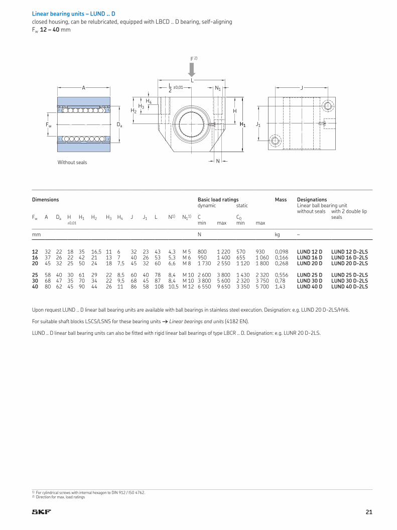
Linear bearing units – LUND .. D
closed housing, can be relubricated, equipped with LBCD .. D bearing, self-aligning
Fw 12 – 40 mm
12 32 22 18 35 16,5 11 6 32 23 43 4,3 M 5 800 1 220 570 930 0,098 LUND 12 D LUND 12 D-2LS16 37 26 22 42 21 13 7 40 26 53 5,3 M 6 950 1 400 655 1 060 0,166 LUND 16 D LUND 16 D-2LS20 45 32 25 50 24 18 7,5 45 32 60 6,6 M 8 1 730 2 550 1 120 1 800 0,268 LUND 20 D LUND 20 D-2LS
25 58 40 30 61 29 22 8,5 60 40 78 8,4 M 10 2 600 3 800 1 430 2 320 0,556 LUND 25 D LUND 25 D-2LS30 68 47 35 70 34 22 9,5 68 45 87 8,4 M 10 3 800 5 600 2 320 3 750 0,78 LUND 30 D LUND 30 D-2LS40 80 62 45 90 44 26 11 86 58 108 10,5 M 12 6 550 9 650 3 350 5 700 1,43 LUND 40 D LUND 40 D-2LS
Upon request LUND .. D linear ball bearing units are available with ball bearings in stainless steel execution. Designation: e.g. LUND 20 D-2LS/HV6.
For suitable shaft blocks LSCS/LSNS for these bearing units † Linear bearings and units (4182 EN).
LUND .. D linear ball bearing units can also be fitted with rigid linear ball bearings of type LBCR .. D. Designation: e.g. LUNR 20 D-2LS.
Dimensions Basic load ratings Mass Designationsdynamic static Linear ball bearing unit
without seals with 2 double lip sealsFw A Da H H1 H2 H3 H4 J J1 L N1) N1
1) C C0?0,01 min max min max
mm N kg –
1) For cylindrical screws with internal hexagon to DIN 912 / ISO 4762.2) Direction for max. load ratings
H1
HH2
H3
H4
LL2?0,01A
Fw Da
J
N
H1 J1
N1
F
Without seals
2)
21

Linear bearing units – LUNE .. D
slotted housing, can be relubricated, clearance adjustable, equipped with LBCD .. D bearing, self-aligning
Fw 12 – 40 mm
12 32 22 18 35 16,5 11 6 32 23 43 4,3 M 5 800 1 220 570 930 0,097 LUNE 12 D LUNE 12 D-2LS16 37 26 22 42 21 13 7 40 26 53 5,3 M 6 950 1 400 655 1 060 0,165 LUNE 16 D LUNE 16 D-2LS20 45 32 25 50 24 18 7,5 45 32 60 6,6 M 8 1 730 2 550 1 120 1 800 0,268 LUNE 20 D LUNE 20 D-2LS
25 58 40 30 61 29 22 8,5 60 40 78 8,4 M 10 2 600 3 800 1 430 2 320 0,556 LUNE 25 D LUNE 25 D-2LS30 68 47 35 70 34 22 9,5 68 45 87 8,4 M 10 3 800 5 600 2 320 3 750 0,782 LUNE 30 D LUNE 30 D-2LS40 80 62 45 90 44 26 11 86 58 108 10,5 M 12 6 550 9 650 3 350 5 700 1,385 LUNE 40 D LUNE 40 D-2LS
Upon request LUNE .. D linear ball bearing units are available with ball bearings in stainless steel execution. Designation: e.g. LUNE 20 D-2LS/HV6
For suitable shaft blocks LSCS/LSNS for these bearing units † Linear bearings and units (4182 EN).
LUNE .. D linear ball bearing units can also be fitted with rigid linear ball bearings of type LBCR .. D. Designation: e.g. LUNS 20 D-2LS.
Dimensions Basic load ratings Mass Designationsdynamic static Linear ball bearing unit
without seals with 2 double lip sealsFw A Da H H1 H2 H3 H4 J J1 L N1) N1
1) C C0?0,01 min max min max
mm N kg –
1) For cylindrical screws with internal hexagon to DIN 912 / ISO 4762.2) Direction for max. load ratings
H1
H
L
A
Fw
L2?0,01 J
J1
H2
H3
H4
Da
N
N1
F
Without seals
2)
22

Flanged linear bearing units – LVCR .. D
closed housing, equipped with LBCR .. D bearing
Fw 12 – 40 mm
12 20 8 32 22 32 30 42 5,5 930 1 370 695 1 120 0,118 LVCR 12 D-2LS16 22 8 36 26 38 35 50 5,5 1 080 1 600 800 1 290 0,166 LVCR 16 D-2LS20 28 10 45 32 46 42 60 6,6 2 200 3 250 1 630 2 650 0,327 LVCR 20 D-2LS
25 40 12 58 40 58 54 74 6,6 3 100 4 550 2 360 3 800 0,678 LVCR 25 D-2LS30 48 14 68 47 66 60 84 9 4 800 7 100 3 550 5 700 0,97 LVCR 30 D-2LS40 56 16 80 62 90 78 108 11 7 650 11 200 5 100 8 300 1,85 LVCR 40 D-2LS
Upon request LVCR .. D linear ball bearing units are available with ball bearings in stainless steel execution (housing out of cast iron). Designation: e.g. LVCR 20 D-2LS/HV6
LVCR .. D linear ball bearing units of sizes Fw 12–40 can also be fitted with linear bearings which are self-aligning. Designation: e.g. LVCD 20 D-2LS.
Dimensions Basic load ratings Mass Designationsdynamic static Linear bearing unit
with 2 double lip seals2)
Fw A A1 C Da D2 J L N1) C C0
min max min max
mm N kg
1) For cylindrical screws with internal hexagon to DIN 912 / ISO 4762.2) Linear ball bearings fitted to these units are secured using grooved pins - DIN EN ISO 8739 and DIN EN ISO 8744. They are not designed for relubrication. 3) Direction for max. load ratings
C
L
DaD2 L
A
Fw
J
J
N
A1
F
With 2 double lip seals
3)
23
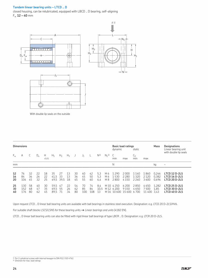
1) For 2 cylindrical screws with internal hexagon to DIN 912 / ISO 4762.2) Direction for max. load ratings
Tandem linear bearing units – LTCD .. D
closed housing, can be relubricated, equipped with LBCD .. D bearing, self-aligning
Fw 12 – 40 mm
12 76 32 22 18 35 27 13 30 40 42 5,3 M 6 1 290 2 000 1 140 1 860 0,246 LTCD 12 D-2LS16 84 36 26 22 41,5 33 13 36 45 50 5,3 M 6 1 530 2 280 1 320 2 120 0,382 LTCD 16 D-2LS20 104 45 32 25 49,5 39,5 18 45 55 60 6,4 M 8 2 800 4 150 2 240 3 600 0,696 LTCD 20 D-2LS
25 130 58 40 30 59,5 47 22 54 70 74 8,4 M 10 4 250 6 200 2 850 4 650 1,282 LTCD 25 D-2LS30 152 68 47 35 69,5 55 26 62 85 84 10,5 M 12 6 200 9 150 4 650 7 500 1,85 LTCD 30 D-2LS40 176 80 62 45 89,5 71 34 80 100 108 13 M 16 10 600 15 600 6 700 11 400 3,43 LTCD 40 D-2LS
Upon request LTCD .. D linear ball bearing units are available with ball bearings in stainless steel execution. Designation: e.g. LTCD 20 D-2LS/HV6.
For suitable shaft blocks LSCS/LSNS for these bearing units † Linear bearings and units (4182 EN).
LTCD .. D linear ball bearing units can also be fitted with rigid linear ball bearings of type LBCR .. D. Designation: e.g. LTCR 20 D-2LS.
Dimensions Basic load ratings Mass Designationsdynamic static Linear bearing unit
with double lip sealsFw A C Da H H1 H2 H3 J J1 L N1) N1
1) C C0 ?0,01 min max min max
mm N kg –
H1
HH2
H3
LA
FwDa
C
N
N1
J
J1
F
With double lip seals on the outside
2)
24

Quadro linear bearing units – LQCD .. D
closed housing, can be relubricated, equipped with LBCD .. D bearing, self-aligning
Fw 12 – 40 mm
1) For 4 cylindrical screws with internal hexagon to DIN 912 / ISO 4762.2) Direction for max. load ratings
12 32 22 16 32 25 13 73 85 42 5,3 M 6 2 120 3 200 2 280 3 750 0,512 LQCD 12 D-2LS16 36 26 18 36 29 13 88 100 54 5,3 M 6 2 500 3 650 2 600 4 250 0,764 LQCD 16 D-2LS20 45 32 23 46 37,5 18 115 130 72 6,6 M 8 4 550 6 700 4 500 7 200 1,732 LQCD 20 D-2LS
25 58 40 28 56 45 22 140 160 88 8,4 M 10 6 800 10 000 5 700 9 300 3,114 LQCD 25 D-2LS30 68 47 32 64 50,5 26 158 180 96 10,5 M 12 10 000 14 600 9 300 15 000 4,23 LQCD 30 D-2LS40 80 62 40 80 64 34 202 230 122 13,5 M 16 17 300 25 500 13 400 22 800 8,14 LQCD 40 D-2LS
Upon request LQCD .. D linear ball bearing units are available with ball bearings in stainless steel execution. Designation: e.g. LQCD 20 D-2LS/HV6
For suitable shaft blocks for these bearing units, designation LEAS .. A and LEAS .. B † Linear bearings and units (4182 EN).
LQCD .. D linear ball bearing units can also be fitted with rigid linear ball bearings of type LBCR .. D. Designation: e.g. LQCR 20 D-2LS.
Dimensions Basic load ratings Mass Designationsdynamic static Linear bearing unit
with double lip sealsFw C Da H H1 H2 H3 J L L1 N1) N1
1) C C0 ?0,01 min max min max
mm N kg –
L1
H1
H
LL
FwDa
C
N
N1
J
J
H2
H3
F
With double lip seals on the outside
2)
25

26

Please complete the form with all available information and send it to your SKF representative or authorized distributor for product selection.
SKF contact Date
General information
Customer ContactCompany Contact name
Address Job title
Address Department
Post code / Zip City State Phone (including country code) Mobile (including country code)
Country Mail
Reason for requestCurrent product / brand Description
○ Replacement ○ New design ○ Other
Application / Industry
○ Factory automation ○ Food and beverage ○ Machine tools Description
○ Medical ○ Semiconductor ○ Other
Application description
Specification sheet – Linear Ball bearing
27

Stroke Shaft length Center distance between or Short part dimensions Guiding systembearings, c shafts, d Length Width Maximum height
mm mm mm mm mm mm mm
○ No constraints
Required service life distance or time (fill in all fields) Required static safety (in accordance to your business and application)Distance Total time Period of one cycle Stroke of one cycle
km h s mm
Maximum speed) Maximum acceleration) Rigidity of guiding system Running accuracy of guiding systemParallelism in height
m/s m/s N/µm µm
) Here the maximum values. Enter load phase specific values in table “External loads and load phases”
Parallelism in sideward direction
○ No specific requirements µm
EnvironmentPresence of dust, dirt or fluids Requirements on friction Preferred sealing version
○ Clean environment, e.g. laboratory ○ Lowest possible friction ○ Shield
○ Standard industrial environment ○ Standard friction ○ Sealing on one side (-LS)
○ Dirty environment, e.g. milling machine ○ No requirement ○ Sealing on both sides (-LS)○ Additional sealing
○ Humid or corrosive environment Preferred material
If yes, please describe: ○ No preference (standard)
○ Stainless steel balls and raceways
○ Stainless steel shaft
○ Chrome plated shaft
Temperature [°C]Minimum Operating Maximum ○ Shock loads or vibrations
If yes, please describe:
Lubricant
○ Standard prelubrication by SKF, as stated in the catalogue. ○ OtherPlease specify:
Sketch of the application (or attach a drawing)
Specification sheet – Linear Ball bearing
28

Product details
Product designation (if already known)
ISO series (ISO ) Bearing type Bearing design
○ ISO Series ○ Linear ball bearing ○ Closed design
○ ISO Series ○ Linear plain bearing ○ Open design (for supported shafts)
○ Non self aligning (permissible shaft deflection without reduction ±′ of arc)○ Self aligning (permissbile shaft deflection ±′ of arc)
Needed accessories (for details see SKF publication , Linear ball bearings and units)
○ Shaft Designation Length Shafting standard ○ Housing Designation
LJ … mm ESSC …
○ Single shaft block
Designation ○ Tandem shaft block
Designation
LS … LE …
Linear ball bearings mounted as a complete system
○ System Designation ○ System with drive, e.g. ball screwLZ …
Specification sheet – Linear Ball bearing
29

Input for dimensioning calculation
○ No preference If yes, please describe:
○ Other
Moving direction (set coordinate system accordingly)Please specify:
○ Horizontal ○ Vertical ○ Other
External loads and load phases
Forces in N, Lever arms in mm measured from defined origin (see graphics above). If the application has more than load phases, please copy this page.
Load phase Load phase Load phase
Stroke mm Stroke mm Stroke mm
Acceleration mm/s Acceleration mm/s Acceleration mm/s
Speed m/s Speed m/s Speed m/s
Lever arms in Lever arms in Lever arms in
Force Fx x y z Force Fx x y z Force Fx x y z
Force Fy x y z Force Fy x y z Force Fy x y z
Force Fz x y z Force Fz x y z Force Fz x y z
Specification sheet – Linear Ball bearing
+Fy
+y
+Fz
+z+Fx
+x
ORIGIN
+Fy
+y
+Fz+z
+Fx
+x
ORIGIN
c
1
2
+Fy
+y
+Fz
+z
+Fx
+x
ORIGIN
2
1
d
+Fy
+y
+Fz+z
+Fx
+x
ORIGIN
c
4
3
1
2
d
○ Config
○ Config
○ Config
○ Config
30

31

® SKF is a registered trademark of the SKF Group.
© SKF Group 2016The contents of this publication are the copyright of the publisher and may not be reproduced (even extracts) unless prior written permission is granted. Every care has been taken to ensure the accuracy of the information contained in this publication but no liability can be accepted for any loss or damage whether direct, indirect or consequential arising out of the use of the information contained herein.
PUB MP/P2 14058/3 EN · February 2016
Certain image(s) used under license from Shutterstock.com
skf.com