LATERAL LOAD BEHAVIOR OF A CONTAINMENT INTERNAL …ahvarma/Publications/Pap_862_ver_4.pdfThis paper...
11
Transactions, SMiRT-22 San Francisco, California, USA - August 18-23, 2013 Division V LATERAL LOAD BEHAVIOR OF A CONTAINMENT INTERNAL STRUCTURE CONSISTING OF COMPOSITE SC WALLS Amit H.Varma 1 , Kadir C. Sener 2 , and Mitsubishi Heavy Industries 3 1 Assoc. Professor, School of Civil Eng., Purdue University, West Lafayette, IN ([email protected]) 2 Ph.D. Candidate, School of Civil Eng., Purdue University, West Lafayette, IN ([email protected]) 3 Mitsubishi Heavy Industries, LTD., Kobe, Japan ABSTRACT This paper presents the lateral load behavior of a 1/10th scale model of a pressurized water reactor (PWR) containment internal structure (CIS). The entire CIS including the steam generator compartments, pressurizer, reactor cavity walls, etc. is made of steel-concrete composite (SC) walls. The behavior of this 1/10th scale model of the entire CIS was investigated experimentally previously by researchers in Japan (Akiyama et al. 1989). This important and seminal work was funded by Mitsubishi Heavy Industries (MHI), Japanese Atomic Power Co., and Obayashi Corporation, and presented at the 10th SMiRT Conference in 1989. Recent advancements in finite element modeling techniques, and computer-based numerical analysis approaches have enabled detailed numerical analysis and evaluation of the lateral load behavior of the 1/10th scale SC containment internal structure. This paper presents: (i) the development of 3D finite element models for the 1/10th scale structure, (ii) the comparison and evaluation of analytical results with experimental results and observations, and (iii) the overall lateral load-deformation behavior of the complete structure including the formation of ductile energy dissipating mechanisms. The experimental and analytical results are also used to provide recommendations for modeling CIS structures for conducting seismic analysis. INTRODUCTION The use of steel-concrete composite (SC) walls in safety-related nuclear facilities has become more prevalent in the past few years. Experimental and analytical research has been conducted on the seismic behavior (including in-plane shear and out-of-plane shear behavior) of SC walls and components. However, there is limited information and knowledge regarding the lateral load (seismic) behavior of the whole structure composite of SC walls. The seismic behavior of a pressurized water reactor (PWR) containment internal structure (CIS) that was composed entirely of SC walls was evaluated experimentally by conducting a cyclic lateral load-deformation test on a 1/10 th scale model of the entire CIS. Mitsubishi Heavy Industries (MHI), Japanese Atomic Power Co., and Obayashi Corporation conducted this experimental evaluation in 1983 (Akiyama et al. 1989). The experimental results provide significant information and insights into the lateral load- deformation behavior of CIS composed entirely of SC walls. It is evident that such tests cannot be repeated without significant expense in terms of cost and schedule. The experimental results are of limited value until the overall structure behavior can be predicted analytically and assimilated using simple behavior models. Therefore, this paper presents the development and verification of a nonlinear finite element modeling approach for modeling and predicting the lateral load-deformation behavior of the 1/10 th scale model of the CIS composed of SC walls. The modeling approach is benchmarked using the experimental results, and the benchmarked modeling approach is recommended for evaluating the lateral load- deformation behavior of comparable structures composed of SC walls.
Transcript of LATERAL LOAD BEHAVIOR OF A CONTAINMENT INTERNAL …ahvarma/Publications/Pap_862_ver_4.pdfThis paper...

Transactions, SMiRT-22
San Francisco, California, USA - August 18-23, 2013 Division V
LATERAL LOAD BEHAVIOR OF A CONTAINMENT INTERNAL STRUCTURE CONSISTING OF COMPOSITE SC WALLS
Amit H.Varma1, Kadir C. Sener2, and Mitsubishi Heavy Industries3
1 Assoc. Professor, School of Civil Eng., Purdue University, West Lafayette, IN ([email protected]) 2 Ph.D. Candidate, School of Civil Eng., Purdue University, West Lafayette, IN ([email protected]) 3 Mitsubishi Heavy Industries, LTD., Kobe, Japan ABSTRACT
This paper presents the lateral load behavior of a 1/10th scale model of a pressurized water reactor
(PWR) containment internal structure (CIS). The entire CIS including the steam generator compartments, pressurizer, reactor cavity walls, etc. is made of steel-concrete composite (SC) walls. The behavior of this 1/10th scale model of the entire CIS was investigated experimentally previously by researchers in Japan (Akiyama et al. 1989). This important and seminal work was funded by Mitsubishi Heavy Industries (MHI), Japanese Atomic Power Co., and Obayashi Corporation, and presented at the 10th SMiRT Conference in 1989. Recent advancements in finite element modeling techniques, and computer-based numerical analysis approaches have enabled detailed numerical analysis and evaluation of the lateral load behavior of the 1/10th scale SC containment internal structure. This paper presents: (i) the development of 3D finite element models for the 1/10th scale structure, (ii) the comparison and evaluation of analytical results with experimental results and observations, and (iii) the overall lateral load-deformation behavior of the complete structure including the formation of ductile energy dissipating mechanisms. The experimental and analytical results are also used to provide recommendations for modeling CIS structures for conducting seismic analysis. INTRODUCTION
The use of steel-concrete composite (SC) walls in safety-related nuclear facilities has become more prevalent in the past few years. Experimental and analytical research has been conducted on the seismic behavior (including in-plane shear and out-of-plane shear behavior) of SC walls and components. However, there is limited information and knowledge regarding the lateral load (seismic) behavior of the whole structure composite of SC walls. The seismic behavior of a pressurized water reactor (PWR) containment internal structure (CIS) that was composed entirely of SC walls was evaluated experimentally by conducting a cyclic lateral load-deformation test on a 1/10th scale model of the entire CIS. Mitsubishi Heavy Industries (MHI), Japanese Atomic Power Co., and Obayashi Corporation conducted this experimental evaluation in 1983 (Akiyama et al. 1989).
The experimental results provide significant information and insights into the lateral load-deformation behavior of CIS composed entirely of SC walls. It is evident that such tests cannot be repeated without significant expense in terms of cost and schedule. The experimental results are of limited value until the overall structure behavior can be predicted analytically and assimilated using simple behavior models. Therefore, this paper presents the development and verification of a nonlinear finite element modeling approach for modeling and predicting the lateral load-deformation behavior of the 1/10th scale model of the CIS composed of SC walls. The modeling approach is benchmarked using the experimental results, and the benchmarked modeling approach is recommended for evaluating the lateral load-deformation behavior of comparable structures composed of SC walls.
22nd Conference on Structural Mechanics in Reactor Technology
San Francisco, California, USA - August 18-23, 2013 Division V
APPROACH The commercial finite element analysis program ABAQUS was used to develop and analyze 3D
finite element models of the 1/10th scale CIS composed of SC walls. Models with different levels of complexity were developed and analyzed to: (i) identify the level of complexity needed to model particular aspects of behavior, and (ii) develop better understanding of the lateral load-deformation behavior of the structure and the associated limit states.
3D finite element models were first developed and analyzed for monotonically increasing lateral loading. These models included plasticity based constitutive models for the steel and concrete materials. Two different options were considered for the bond interaction between the steel faceplates and concrete infill of the SC walls: (i) full bond, and (ii) partial bond based on shear connector behavior. The results from the monotonic analysis were compared to the envelope of the cyclic lateral load-deformation response from the experiment. These comparisons were used to finalize the input parameters, and to select between the two bond interaction models.
The selected model was analyzed for the cyclic lateral loading (and deformation) history from the test. The steel and concrete material constitutive models were further enhanced to include cyclic stress-strain hysteresis rules, damage models, and material fracture models. The analysis results were compared and benchmarked with the cyclic lateral load-deformation results from the test.
The following sections summarize the: (i) experimental test, (ii) 3D finite models, (iii) steel and concrete constitutive models, (iv) monotonic analysis results, (v) cyclic analysis results and comparison with experimental behavior, and (vi) conclusions with modeling recommendations.
EXPERIMENTAL TEST DETAILS
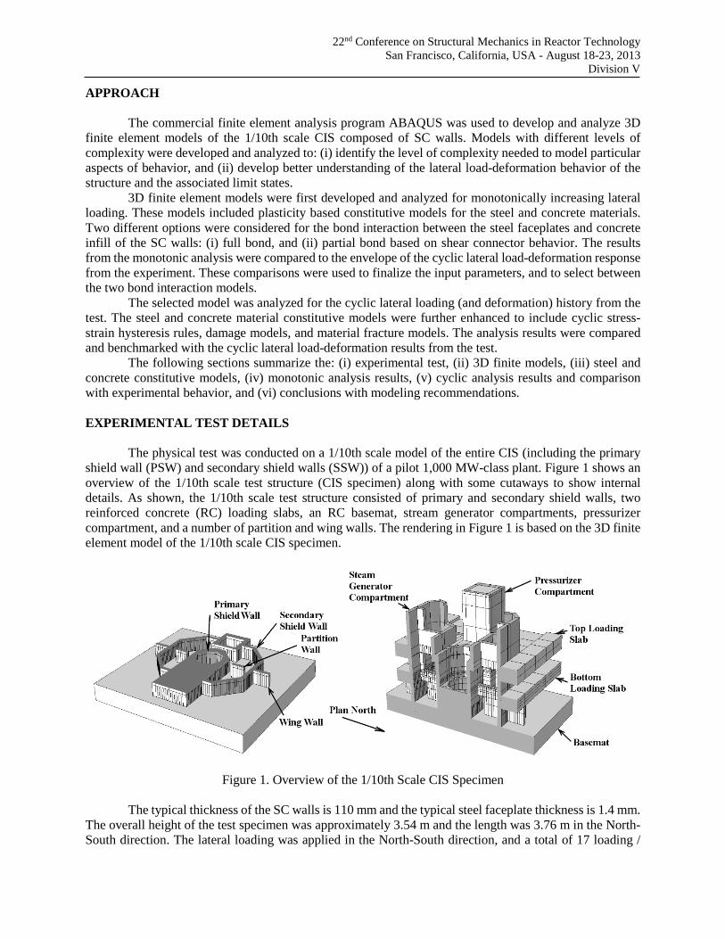
The physical test was conducted on a 1/10th scale model of the entire CIS (including the primary shield wall (PSW) and secondary shield walls (SSW)) of a pilot 1,000 MW-class plant. Figure 1 shows an overview of the 1/10th scale test structure (CIS specimen) along with some cutaways to show internal details. As shown, the 1/10th scale test structure consisted of primary and secondary shield walls, two reinforced concrete (RC) loading slabs, an RC basemat, stream generator compartments, pressurizer compartment, and a number of partition and wing walls. The rendering in Figure 1 is based on the 3D finite element model of the 1/10th scale CIS specimen.
Figure 1. Overview of the 1/10th Scale CIS Specimen
The typical thickness of the SC walls is 110 mm and the typical steel faceplate thickness is 1.4 mm. The overall height of the test specimen was approximately 3.54 m and the length was 3.76 m in the North-South direction. The lateral loading was applied in the North-South direction, and a total of 17 loading /

22nd Conference on Structural Mechanics in Reactor Technology
San Francisco, California, USA - August 18-23, 2013 Division V
deformation cycles were applied. Most of initial nine loading cycles were applied in load control, and the subsequent eight loading cycles were applied in displacement control. The displacement-controlled cycles were applied by: (i) controlling the top RC slab displacement and increasing it gradually every cycle, while (ii) maintaining the force applied to the bottom RC slab at a fixed ratio (top slab force : bottom slab force = 1.0 : 0.39).
Table 1 summarizes the cyclic loading history from the test. As shown, the test structure was first subjected to three load-controlled cycles in the elastic range of the response. This was followed by two displacement-controlled cycles with R = 0.35 x 10⁻³, where R is the ratio of the lateral displacement at the top loading slab divided by its height relative to the basemat. These was followed by loading cycles at the design earthquake (S1) level load, and the beyond design basis earthquake (S2) level load. These nine cycles were primarily in the elastic range of the response. They generated most of the visible concrete cracks in the CIS. The test structure was subjected to seven displacement-controlled cycles with increasing values of lateral displacement (R = 1, 2, 4, 8, 12, and 17 x 10-3 as shown in Table 1). The final (17th) cycle pushed the structure to ultimate failure.
Table 1: Description of Test Loading Cycles
Load Cycle Description Total Applied
Load Load Cycle Description Total Applied
Load
1 Elastic Loading 490 kN 11 R = 2.0 ×10⁻³ 6011 kN
2,3 Elastic Loading 981 kN 12 R = 4.0 ×10⁻³ 8081 kN
4,5 R = 0.35 × 10⁻³ 1393 kN 13,14 R = 8.0 ×10⁻³ 10179 kN 6,7 S1 load 2089 kN 15 R = 12 ×10–3 10954 kN 8,9 S2 load 3138 kN 16 R = 17 ×10–3 11493 kN 10 R = 1.0 ×10⁻³ 4286 kN 17 Ultimate Failure 10787 kN
1/10TH SCALE MODEL: GEOMETRIC DETAILS
The 3D finite element models of the test structure incorporate large-deformation (nonlinear geometric) effects, nonlinear steel material models, and nonlinear concrete material models with smeared cracking in tension. Nonlinear spring elements are used to simulate the bond interaction and composite action between the steel faceplates and concrete infill provided by the steel shear studs and the tie-bars in the SC walls. The models were pre-processed, executed and post-processed using the FEM software package ABAQUS CAE. A quasi-static explicit analysis procedure was used to conduct the analyses while accounting for the effects of large-deformations and complex material behavior including smeared cracking of cracking, multi-axial plasticity, inelastic damage and fracture.
Figure 2 shows an overview of the FEM model components. On the top left it shows the concrete infill of the PSW, the SSW, the steam generator compartments, and the pressurizer compartment. The concrete infill is connected directly to the concrete basemat. The RC loading slabs are shown in the bottom left of Figure 2. The bottom RC loading slab is connected to the concrete infill at the outer surface of the SSW. The top RC loading slab is also connected to the outer surface of the SSW. The top RC slab has interior regions that connect the upper steam generator compartments to the PSW and the SSW. The steel faceplates and web plates are shown in the top right side of Figure 2. The steel faceplates line the inner and outer surfaces of all of the concrete infill walls and components. The steel plates extend partially into the concrete basemat and are anchored at the locations where they are terminated. The tie bar elements are shown in the lower right of Figure 2. These elements are: (i) connected to the steel plates with special connector elements, and (ii) embedded in the concrete elements.
22nd Conference on Structural Mechanics in Reactor Technology
San Francisco, California, USA - August 18-23, 2013 Division V
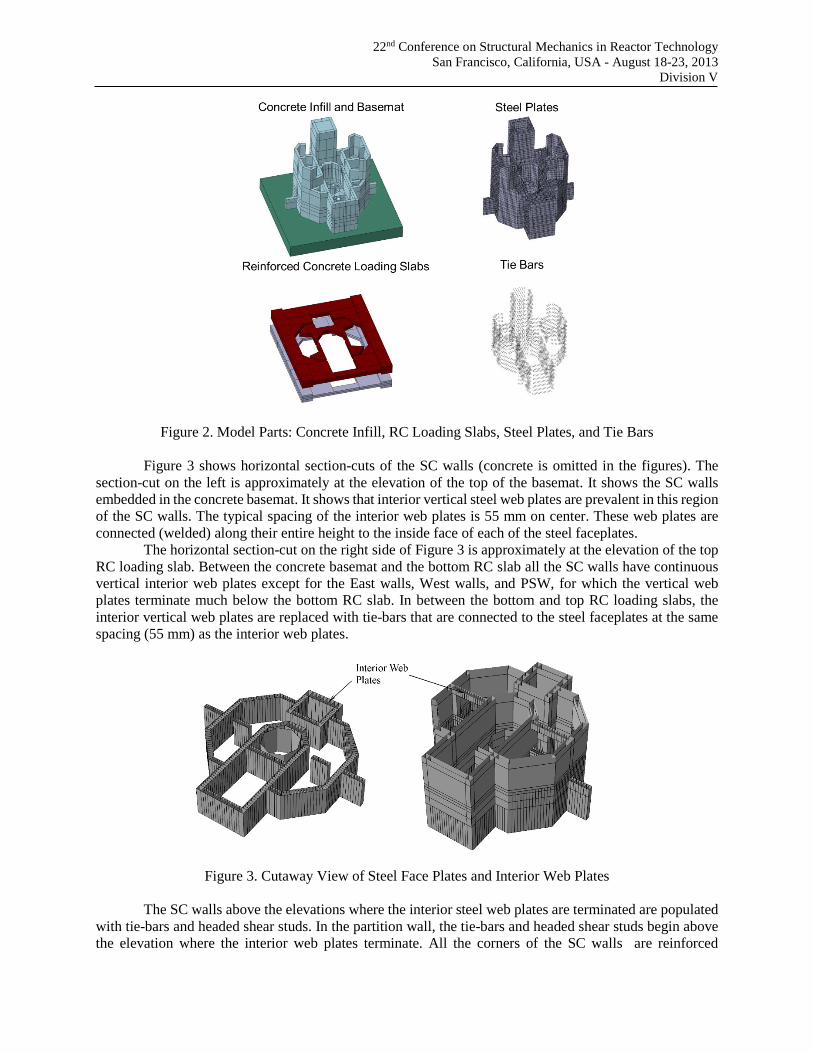
Figure 2. Model Parts: Concrete Infill, RC Loading Slabs, Steel Plates, and Tie Bars
Figure 3 shows horizontal section-cuts of the SC walls (concrete is omitted in the figures). The section-cut on the left is approximately at the elevation of the top of the basemat. It shows the SC walls embedded in the concrete basemat. It shows that interior vertical steel web plates are prevalent in this region of the SC walls. The typical spacing of the interior web plates is 55 mm on center. These web plates are connected (welded) along their entire height to the inside face of each of the steel faceplates.
The horizontal section-cut on the right side of Figure 3 is approximately at the elevation of the top RC loading slab. Between the concrete basemat and the bottom RC slab all the SC walls have continuous vertical interior web plates except for the East walls, West walls, and PSW, for which the vertical web plates terminate much below the bottom RC slab. In between the bottom and top RC loading slabs, the interior vertical web plates are replaced with tie-bars that are connected to the steel faceplates at the same spacing (55 mm) as the interior web plates.
Figure 3. Cutaway View of Steel Face Plates and Interior Web Plates
The SC walls above the elevations where the interior steel web plates are terminated are populated with tie-bars and headed shear studs. In the partition wall, the tie-bars and headed shear studs begin above the elevation where the interior web plates terminate. All the corners of the SC walls are reinforced

22nd Conference on Structural Mechanics in Reactor Technology
San Francisco, California, USA - August 18-23, 2013 Division V
throughout the structure using continuous web plates that are welded to the inside and outside corners and extend the full corner height vertically. The thickness of all of the interior web plates is equal to 1.4 mm, which the same as the typical thickness of the steel faceplates. The measured and reported compressive strength of concrete used in the experiment was 17 MPa (2524 psi). The measured and reported yield strength of the steel plates was 296 MPa (42.9 ksi).
1/10TH SCALE MODEL: MATERIAL MODEL PROPERTIES
The 3D finite element model of the 1/10th scale test was developed and analyzed using
ABAQUS/Explicit, which has a dynamic explicit numerical solver. The ability of ABAQUS/Explicit to effectively handle extreme nonlinear behavior such as concrete cracking and contact interactions makes it particularly suitable for the simulation of quasi-static cyclic loading behavior. The material library in ABAQUS has been used for the modeling the steel and concrete materials in the model.
The 3D finite element model has a global element size of 55 mm, which facilitates having sufficient elements and consistency throughout the model. The concrete infill, loading slabs and the basemat are modeled with reduced integration element solid elements (C3D8R). The steel plates are modeled using 4-node S4R shell elements with reduced integration.
The two RC loading slabs where the lateral forces are applied (shown in Figure 2) and the concrete basemat were modeled with an isotropic linear elastic material model. Using a linear elastic concrete model was a reasonable simplification since the physical slabs were heavily reinforced and did not exhibit substantial cracking, damage, or stress concentrations during the experiment.
Concrete Material Model
The concrete damaged plasticity (CDP) model in ABAQUS consists of a multiaxial plasticity model in compression, smeared cracking model in tension, and isotropic damage rules along with hysteresis rules for cyclic behavior. It can be used for monotonic or cyclic analyses with dynamic implicit or explicit procedures. It is particularly effective in modeling cyclic inelastic behavior with damage.
The parameters used to define the CDP model were: (i) the uniaxial compression stress-plastic strain curve, which was defined using the modified Popovic’s empirical stress-strain model. (ii) The uniaxial tension stress-crack opening displacement curve that was defined using the equations for plain concrete provided in CEB-FIP Model Code (1990). (iii) The ratio of biaxial compressive strength to uniaxial strength was assumed to be equal to 1.16. (iv) The ratio of compressive to tensile meridians of the yield surface in Π (deviatoric stress) space was assumed to be equal to 0.67. (v) The dilation angle was specified to be 15 degrees for unconfined concrete. It was calibrated by Candappa et al. (2001) using experimental data for axial and lateral stress-strain behavior. (vi) The value of the eccentricity ratio was specified to be 0.1.
The CDP material model is effective in simulating cyclic behavior because it incorporates hysteresis rules and cyclic damage models. Stiffness degradation in compression and tension are controlled by the parameters dc and dt. These damage parameters were specified as functions of the inelastic strains in compression and tension. The damage increased with increasing inelastic strains in the concrete. The stiffness recovery upon load reversal (from compression to tension) is controlled by parameters wc and wt that can be specified with values between 0 (no recovery) and 1 (full recovery). The default values with no recovery when reversing from compression to tension, and full recovery when reversing from tension to compression were used.
Concrete spalling is prevented in SC walls because the concrete infill is surrounded by steel faceplates. This is contrary to the behavior of RC walls where concrete spalling is observed under cyclic loading. The element removal (deletion) feature was not implemented for rgw concrete elements in SC walls because they are expected to undergo crack closure upon load reversals and participate in the load carrying mechanism.
22nd Conference on Structural Mechanics in Reactor Technology
San Francisco, California, USA - August 18-23, 2013 Division V
Steel Material Model
A multiaxial plasticity model is used for the steel material. The model consists of: (i) a von Mises yield surface, (ii) associated flow rule, and (iii) combined hardening rules. The combined hardening rules utilize features from both isotropic and kinematic hardening models, and are defined using the half cycle data of uniaxial tension stress-strain behavior of the steel material.
The initial monotonic and cyclic analyses are conducted using the multiaxial plasticity model for the steel material. This model is further improved for the final cyclic analysis by including ductile damage and fracture (element deletion) criterion to prevent excessive (unrealistic) plastic strains in the models. Ductile damage is assumed to initiate at 13.5% effective plastic strain, and increase linearly to full damage at 15% effective plastic strain. The fully damaged steel element is removed from the finite element mesh using the ductile failure feature in the program. A combined hardening model for the steel plates are used that includes properties of both kinematic and isotropic hardening. By defining the essential parameters the steel material under cyclic loading are simulated more accurately.
Shear Stud and Tie Bar Models
Shear studs provide bond interaction and composite action between the steel faceplates and concrete infill. They were modeled using connector elements in ABAQUS. These connector elements can be used to model the mechanical connection between any two nodes in the finite element mesh by specifying the fundamental force-displacement and moment-rotation relationships for the connected degrees-of-freedoms.
The shear stud connector elements were defined between coinciding steel faceplate nodes and concrete nodes at the shear stud locations in the SC walls. This reduces the complexity of modeling the actual headed shear stud, its embedded interaction with the concrete, and the behavior of the weld that connects the shear stud to the steel plate.
In the in-plane direction (parallel to the steel plate surface), the shear stud connector elements are specified to follow the empirical force-displacement (slip) model developed by Ollgaard et al. (1971) for shear studs. This empirical model is a function of the stud diameter, steel tensile strength, and concrete compressive strength. In the out-of-plane direction, the studs behave elastically based on the axial stiffness of the shear stud area.
The steel tie-bars in SC walls contribute to: (i) the out-of-plane shear resisting mechanism (by developing axial tension), and (ii) the bond interaction (interfacial shear transfer) between the steel plate and concrete infill similar to shear studs. These two capabilities of the steel tie-bars are modeled appropriately in the finite element models. The out-of-plane shear resisting mechanism is represented by modeling the tie-bar with shear flexible inelastic beam elements that are embedded in the concrete elements. The bond interaction (interfacial shear resisting) mechanism is represented using connector elements similar to those used for the shear stud models.
In the 1/10th scale test structure, the headed shear studs and tie bars had: (i) diameter of 3 mm, (ii) orthogonal grid spacing of 25 mm by 25 mm for the studs, and (iii) orthogonal grid spacing of 55mm by 55mm for tie bars. In the finite element model, the spacing of the shear stud connector elements was increased to 55 mm to match the size of the finite element mesh. The associated connector element properties (including force-displacement behavior) were modified appropriately based on the tributary area per stud to account for the reduced density of connector elements used in the model. MONOTONIC ANALYSIS RESULTS
This section presents the results from the monotonic lateral loading analyses of the finite element models for the 1/10th scale test structure. Two separate analyses were conducted on models that were almost

22nd Conference on Structural Mechanics in Reactor Technology
San Francisco, California, USA - August 18-23, 2013 Division V
identical to each other with the exception that one model had a fully-tied, i.e., no slip bond interaction model between the steel faceplates and the concrete infill. The second model accounted for the bond interaction between the steel faceplates and the concrete infill using connector models for the shear studs and tie bar contributions as explained above.
Figure 5 compares the results from the monotonic analyses with the envelopes of the cyclic lateral load-deformation responses from the experiment. As shown in Figure 5, the base shear vs. top slab displacement responses from the monotonic analyses of: (i) the full-tied model, and (ii) the model with connector elements are almost identical. The results from both analyses compare favorably with the experimental lateral load-displacement response envelopes. Additionally, the models predict the experimental response conservatively up to the lateral displacement of 40 mm. Figure 4 shows the deflected shape of the test structure predicted by the finite element models at 30 mm lateral displacement in the top slab. The figure includes contour plots of the lateral deflections on a 3D isometric view and an elevation view of the displaced shape of the structure.
Figure 4. Deformed shape at 30 mm lateral displacement: (a) i isometric view, and (b) elevation view.
Figure 5. Comparison of Lateral Load-Displacement Responses from Monotonic Analyses
In the 1/10th scale test, cyclic loading was applied up to 30 mm lateral displacement, and then the structure (CIS specimen) was pushed monotonically until failure. The monotonic analysis results do not follow the experimental behavior trend after 35 mm lateral displacement because the corresponding models do not include cyclic degradation and damage effects. This limitation is addressed by the cyclic analysis results presented in the next section.
0
2000
4000
6000
8000
10000
12000
14000
0 10 20 30 40 50 60
Tota
l Bas
e Sh
ear
(kN
)
Displacement (mm)
1/10th Scale Test - Load vs. Top Slab Displacement
Test Result - Push
Test Result - Pull
Monotonic TieModelMonotonicConnector Model
εsp > 5%

22nd Conference on Structural Mechanics in Reactor Technology
San Francisco, California, USA - August 18-23, 2013 Division V
Figure 5 also includes a data point on the analytically predicted load-displacement curves to indicate when the steel plastic strain value exceeded 5%. Steel plastic strains exceeding 5% (for monotonic loading) may correspond to much larger cumulative plastic strains during cyclic loading, and therefore have been identified as a potential limit for the usability of the monotonic analysis results. As shown in Figure 5, the lateral displacement was approximately 35mm when the steel plastic strain exceeded 5%. This further explains the discrepancy between the monotonic analysis results and the experimental behavior trend for lateral displacements greater than 35 mm. Since both the fully-tied model and the connector model compared favorably with each other, and conservatively with the experimental results, only the tied model was used for conducting the cyclic analysis.
Figure 6 shows the von-Mises stress distribution in the steel plates at 30 mm lateral displacement. The contour plot is limited to maximum value of 300MPa to distinguish the yielded portions, which are shown in grey color. As seen in the figure, steel faceplate yielding occurs in the primary and the secondary shear walls mostly between the concrete basemat and the bottom RC loading slab. The deflected shape in Figure 6 also shows the occurrence of shear buckling in the primary core shear walls, the canal web wall, and the pressurizer outer wall. Similar behavior was also observed in the experimental test results.
Figure 6. Steel Plates Von-Misses Stress Contour
Plot at 30mm Displacement Figure 7. Concrete Maximum Principal Stress (Tensile) Contour Plot at 30mm Displacement
Figure 7 shows the contour plot for the maximum principal stresses in the concrete portions of the
specimen. The figure is limited to 1500 microstrain to show the regions that have fully exhausted the tensile stress carrying capability based on the tension softening curve that was input for the concrete material model. These regions with extensive (smeared) concrete cracking are shown in grey color.
CYCLIC ANALYSIS RESULTS
This section presents the results from the cyclic lateral loading analyses of the finite element model
for the 1/10th scale test structure. The fully-tied finite element model was further enhanced to include cyclic damage and deterioration rules for the concrete and ductile damage rules and fracture criteria for the steel material. The finite element model was subjected to the same lateral loading history as the test structure, i.e., all 17 cycles listed in Table 1.
The results from the cyclic analyses in terms of the lateral load-displacement response for the test structure are shown in Figure 8. The figure also includes the experimentally measured lateral load-displacement response for comparison. As shown, the cyclic analysis results compare favorably and conservatively with the experimental lateral load-displacement response. The incorporation of the ductile damage and deterioration rules for concrete, and the ductile damage and fracture rules for steel have made the analysis results more conservative than the experimental results particularly for larger lateral displacements.

22nd Conference on Structural Mechanics in Reactor Technology
San Francisco, California, USA - August 18-23, 2013 Division V
Figure 8. Cyclic lateral load-displacement (Base Shear – Top Slab Displacement) Responses of 1/10th
Scale Test Structure including Experimental and Analysis Results
Further evaluations and comparisons of the analysis results with experimental observations and results are presented in Figure 9, Figure 10, and Table 2. Figure 9 compares the experimental observations of concrete cracking initiation and progression of concrete cracking with the results from the finite element analyses. As mentioned earlier, the elastic (load-controlled) cycles (1-9) resulted in most of the concrete cracking observed in SC walls below the bottom RC loading slab. The extent of concrete cracking in the finite element models is highlighted by limiting the maximum principal strain value in the contour plots to 100 microstrain, which corresponds to the strain level at concrete tensile cracking initiation. Figure 9 demonstrates excellent agreement between the analysis results and experimental observations.
Table 2 presents numerical comparisons of the experimental and analytical lateral loads (base shear) corresponding to the occurrence of yielding in the steel faceplates of the SC walls. The occurrence of yielding in the tests was established using strains measured by strain gauge rosettes. The occurrence of yielding in the finite element models was established by monitoring the plastic strains in the steel shell elements. The Table presents numerical comparisons of the lateral loads (base shear) corresponding to the occurrence of yielding in all the major SC walls of the CIS including the steam generator compartments, pressurizer, canal walls etc. As shown, the finite element model predicts the occurrence of yielding conservatively in most cases.
Figure 10 shows the final shear fracture failure of the steel faceplates of the pressurizer SC walls during one of the inelastic lateral displacement cycles. Experimental observations indicate that the steel faceplates undergo yielding first, followed by inelastic shear buckling, leading to fracture failure due to cyclic loading. The finite element analysis results also predict fracture failure of the steel faceplates of the pressurizer SC wall at the same location and during the same inelastic loading cycle.

22nd Conference on Structural Mechanics in Reactor Technology
San Francisco, California, USA - August 18-23, 2013 Division V
Figure 9. Progression of Concrete Cracking: (a) Experimental Observations, and (b) Analysis Results
Table 2. Lateral Loads Corresponding to Yielding of Steel Plates in SC Walls of 1/10th Scale Structure
Steel Plate Yielding Initiation Load Levels
Experimental Value (kN)
Finite Element Model (kN)
Side Wall 4374 5000
SG Chamber Flange Wall 8532 7250
Diagonal Wall
Canal Side 7679 7500 Pressurizer Chamber 7679 7500
Partition wall in SG chamber 7669 7250 Canal wall 5796 5800
Pressurizer chamber wall
Inner side 7679 6000 Outer side 8100 6000
Figure 10. Shear Fracture of the Steel Faceplates of the Pressurizer SC Walls: (a) Analysis Model, and
(b) Experimental Observation

22nd Conference on Structural Mechanics in Reactor Technology
San Francisco, California, USA - August 18-23, 2013 Division V
CONCLUSIONS
Researchers in Japan conducted a physical test on a 1/10th scale model of the containment internal structure (CIS) of a pressurized water reactor. The entire CIS was composed of steel-concrete composite (SC) walls. This paper presented the development and benchmarking of a 3D nonlinear inelastic finite element (NIFE) modeling approach for predicting the lateral load – deformation response and the experimental behavior. The 3D nonlinear finite element models were developed and analyzed using ABAQUS, which is a commercially available finite element analysis program.
The models accounted for geometric and material nonlinearity including yielding and local buckling of the steel plates, and tensile cracking and compression plasticity of the concrete. Two different options were considered for the bond interaction between the steel plates and the concrete infill: (i) fully-tied interaction, and (ii) using connector elements to model the bond-slip behavior at the shear stud and tie bar locations. The monotonic lateral load-deformation responses predicted by the NIFE models using both these options were almost identical. The monotonic analysis results compare favorably with the envelope of the experimental cyclic load-deformation response and provide significant insights into experimental behavior (and observations).
The cyclic analyses were conducted on models with fully-tied interaction behavior only. The steel and concrete material models were enhanced to include the cyclic hysteresis rules, effects of cyclic damage and deterioration, and ductile fracture. The cyclic lateral load-deformation responses predicted by the NIFE modeling approach compare favorably with the experimental results. The NIFE modeling approach is recommended for evaluating the lateral load behavior of CIS composed of SC walls.
Both the experimental and analytical result indicate that the lateral load behavior, strength, and ductility of the CIS structure is governed by the in-plane shear behavior and yielding of the steel plates of the primary and secondary shield SC walls. The lateral load capacity (ultimate strength) of the structure was also governed by the in-plane shear failure of the SC walls parallel to the lateral loading direction. This shear failure occurred in regions where the transverse shear reinforcement (web plates) of the SC walls was discontinued abruptly.
REFERENCES
Akiyama,H., Sekimoto,H., Tanaka,M., Inoue,K., Fukihara, M., Okuta,.Y. (1989). “1/l0th Scale Model Test
of Inner Concrete Structure Composed of Concrete Filled Steel Bearing Wall.” Transactions of the 10th International Conference on Structural Mechanics in Reactor Technology (SMiRT-10), IASMIRT, North Carolina State University, Raleigh, NC.
CEB-FIP Model Code (1990). “First complete draft”, fib bulletins 55 and 56, International Federation for Structural Concrete (fib), ISBN 978-2-88394-095-6 and ISBN 978-2- 88394-096-3
Ollgaard,J.G., Slutter,R.G., Fisher,J.W. (1971). “Shear strength of studs connectors in lightweight and normal-weight concrete”, AISC Engineering Journal, Vol. 8, pp. 55–64
Candappa, D.C., Sanjayan, J.G., and Setunge, S., (2001) “Complete Triaxial Stress-Strain Curves of High Strength Concrete.” Journal of Materials in Civil Engineering, ASCE, Vol. 13, No. 3, pp. 209-215.
![CE 160 Labs 9 and 10 Lateral Force Load Path and Lateral ......CE 160 Vukazich Lateral Load Path, IBC Static Seismic Forces [L9, L10] 13/28 Energy Dissipating Capacity of the Lateral](https://static.fdocuments.in/doc/165x107/5ea04670c5ce334f1519d198/ce-160-labs-9-and-10-lateral-force-load-path-and-lateral-ce-160-vukazich.jpg)